

Page 1

Instructions
Integrated Displacement Transmitter
Series DT-120
Non-contacting eddy current displacement transmitter,
loop-powered
Technical alterations reserved!
Page 2

Copyright © 2019 Brüel & Kjaer Vibro GmbH
All rights to this technical documentation remain reserved.
Any corporeal or incorporeal reproduction or dissemination of this technical documentation or making this
document available to the public without prior written approval from Brüel & Kjaer Vibro GmbH is prohibited.
This also applies to parts of this technical documentation.
Instruction Transmitter Series DT-120, C107153002 / v03, en, Release date: 06/09/2019
Hotline:
Brüel & Kjaer Vibro GmbH
Leydhecker Str. 10
64293 Darmstadt
Germany
Phone: +49 6151 428 0 Phone: +49 6151 428 1400
Fax: +49 6151 428 10 00 E-Mail: [email protected]
[email protected]
Page 3

Brüel & Kjaer Vibro │ Instructions
Transmitter Series DT-120
Content
EN
Content
1 Safety 4
1.1 Pictograms and their meaning 4
1.2 Intended use 4
1.2.1 Recommendation to the operator 5
1.3 Restrictions 5
1.4 General information 5
1.5 Personnel requirements 5
2 Product description 6
2.1 General function 6
2.1.1 Measurement type 6
2.1.2 Mechanical versions 7
2.1.3 Wire assignments 8
3 Delivery, storage, transport 9
3.1 Delivery 9
3.2 Storage 9
4 Installation 10
4.1 Assembly of the displacement transmitter 10
4.1.1 DT-121 and DT-122 forward mountable displacement transmitter 11
4.1.2 DT-123 reverse mountable displacement transmitter 11
4.2 Adjusting the installation position of the displacement transmitter 12
4.3 Laying of connecting cable 14
4.4 Electrical connection 14
5 Functional test 15
5.1 Short test 15
5.2 Troubleshooting 15
6 Disassembly 16
6.1 Exchanging a displacement transmitter 16
7 Technical data 17
7.1 Series DT–120 non-contacting displacement transmitter 17
7.2 Environmental requirements 18
7.2.1 Resistance of the displacement transmitter to different media 18
7.2.2 Properties of the measuring track 18
7.2.3 The required clearances and minimum distances for displacement transmitters 19
7.2.4 Calibration 20
8 Disposal 21
Konakt 22
© Brüel & Kjaer Vibro ● C107153002 / v03 ● █ Page 3 of 22
Technical alterations reserved!
Page 4
EN
NOTE!
document carefully before using the product and keep it safely for future reference.
NOTE!
This symbol warns you about dangerous situations that might arise if the product is
1 Safety
This instructions document is an integral part of the product. Read this instructions
1.1 Pictograms and their meaning
This symbol gives general and useful information about using the product.
misused.
1.2 Intended use
The integral displacement transmitter is exclusively for the measurement of mechanical distances and
vibrations. It is primarily used for condition monitoring of plain bearing and rotating shafts.
When transmitters or cables are used in ways which are not described in the relevant operating
instructions, it may cause impairment of function and protection and lead to severe injury to persons,
death or severe, irreversible injuries.
• The transmitter may only be used for the purpose specified in the instructions document. Any
other use will be considered as not in line with the intended use.
Brüel & Kjær Vibro will not be liable for any damage caused by improper use. The risk will be
borne solely by the user.
• Mounted displacement transmitters must not be used as a climbing aid (step).
• Cable installation must not apply any tensile forces to the mounted displacement transmitter.
• The device is only to be operated in permitted environmental conditions. These can be taken
from the technical product specification.
• The electrical equipment must undergo regular maintenance. Problems such as loose
connections, defective plug connections, etc., must be eliminated immediately.
Hot surfaces
• Devices, displacement transmitters or cables can reach dangerous temperatures due to
assembly on external sources of heat or cold (e.g. machine components), whereby touching
these can, amongst other things, cause burns.
Page 4 of 22
Technical alterations reserved!
█ ©Brüel & Kjaer Vibro ● C107153002 / v03
Page 5

Brüel & Kjaer Vibro │ Instructions
NOTE!
installed complies with the requirements of the EU guidelines.
Transmitter Series DT-120
1.2.1 Recommendation to the operator
If dangers should arise during use of the device in connection with machines or parts of the plant
which are outside of Brüel & Kjær Vibro’s responsibility, safety instructions or warnings must be
issued and disseminated by the operating company and understood and confirmed by the personnel
involved.
If the device is installed in a machine or is specified to be part of the construction of a
machine, commissioning is not permitted until the machine in which the device is
Prohibition of unauthorized modifications
The device and accessories may not be altered either constructively or safety-related, without our
express agreement. Any unauthorized modification made excludes liability on our part for any
damages arising.
Safety
EN
1.3 Restrictions
The dynamic output allows connection of a potential-free portable measuring device for system setup
or signal analysis. The dynamic output is current-limited and coupled with high impedance to the loop.
Wrong wiring (for example a short circuit) does not impair the function of the loop. The dynamic
output is not designed for long-term connection to subsequent electronics.
Not all of the possible installation and connection options are described in this document.
1.4 General information
Never use damaged products. Please make a claim for any damage immediately.
1.5 Personnel requirements
Transport, storage, installation, assembly, connection, commissioning, servicing and maintenance
may only be performed by qualified specialist personnel. In doing so it is essential to observe:
• this technical documentation
• warning and safety instructions and symbols affixed to the product
• product-specific regulations and requirements
• all of the national and regional regulations covering safety and the prevention of accidents.
© Brüel & Kjaer Vibro ● C107153002 / v03 ● █ Page 5 of 22
Technical alterations reserved!
Page 6
EN
1
2
3
4
2 Product description
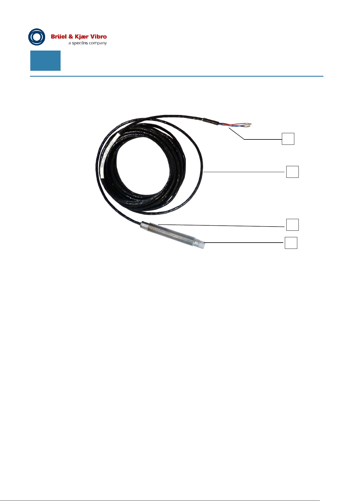
Figure 2-1) Displacement transmitter DT-121.RV/…
1) Cable end, open with 4 conductors (displacement transmitter using 2-conductor technology
plus a dynamic signal output)
2) integral cable
3) displacement transmitter housing
4) ceramic tip
2.1 General function
The integrated Series DT-120 displacement transmitters are based on the non-contacting eddy
current measurement principle, which has proven itself in the field of machine monitoring for several
decades. It allows contactless measurement of the distance between the tip of the displacement
transmitter and an electrically conductive surface to be measured (target).
2.1.1 Measurement type
Based on the distance signal the integral electronics perform one of the following measurements
according to the selected model:
• DT-12x.AP/… AP = Axial Position, measurement of the axial shaft position
• DT-12x.RV/…RV = Radial Vibration, measurement of the radial shaft vibration
(peak to peak value)
Page 6 of 22
Technical alterations reserved!
█ ©Brüel & Kjaer Vibro ● C107153002 / v03
Page 7

Brüel & Kjaer Vibro │ Instructions
Transmitter Series DT-120
Upon connection of the transmitter to a downstream electronic device, the measured loop current
must be converted into the corresponding measurand. The general approach to this is given by the
following formula:
=
In doing so Full Scale (FS) represents the not offset corrected measurement value of the transmitter
for a loop output of 20 mA. Offset is the measurement value which is assigned to the transmitter
output of 4 mA.
For a radial shaft vibration measurement, the Offset is 0 µm peak-peak which corresponds to a
vibration amplitude of zero, i.e. no vibration. For an axial position measurement, a transformation
into the machine-oriented coordinate system can e.g. be performed by setting the Offset
correspondingly.
The unit of the measurement value depends on the selected measurement type respectively
transmitter model. In case of a radial shaft vibration measurement, this is [µm peak-peak] or
[mil peak-peak], while in case of an axial shaft position measurement it is [µm] or [mil] respectively.
The system sensitivity present for a given measurement operation has a direct influence on the
Full Scale value of the transmitter system. Due to the eddy current measurement principle the actual
system sensitivity and therefore also the individual Full Scale value is dependent on the electrical
properties of the target material which is used in the application.
As part of the production process the transmitter is tuned to its standard sensitivity in regard to the
B&K Vibro reference target made out of 42CrMo4 (1.7225 according to EN 10027). In order to obtain
a precise interpretation/conversion of the output loop current, the determination of the system
sensitivity with reference to the shaft or target material used is a mandatory prerequisite.
Section 7.2.4 explains how one can determine the system sensitivity and from this the Full Scale
value for the concrete application by aid of a static calibration device and a suitable material probe.
Section 4.2 contains an installation example for an axial position displacement transmitter.
4
16
Product description
× +
EN
2.1.2 Mechanical versions
The displacement transmitter is available in both a forward and a reverse mount installed version.
• DT-121… Displacement transmitter with continuous thread
• DT-122… Displacement transmitter with continuous thread and pressure-tight
corrugated tube protective hose
• DT-123… Displacement transmitter for reverse mounting
© Brüel & Kjaer Vibro ● C107153002 / v03 ● █ Page 7 of 22
Technical alterations reserved!
Page 8
EN
2.1.3 Wire assignments
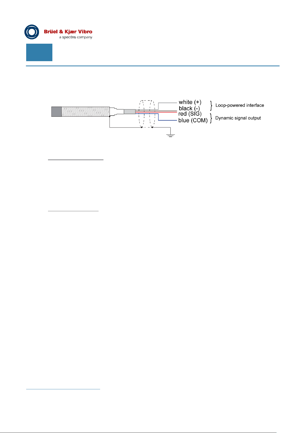
The displacement transmitter has a 4-core integral cable.
Figure 2-2) Displacement transmitter of Series DT-120
Loop-powered interface:
• White ........................ ................... ‘+’ Loop ...... ................... .................... 4-20 mA
• Black ........................ ................... ‘–‘ Loop ...... ................... .................... 4-20 mA
Via the loop-powered interface the displacement transmitter is supplied with +24 VDC and a
4 – 20 mA signal is outputted.
Dynamic signal output:
• Red .......................... ................... ‘+’ ................ ................... .................... SIG
• Blue .......................... ................... ‘–‘ ............... ................... .................... COM
The additional dynamic signal output can be used for simple system set up or signal analysis.
designed for long-term connection to subsequent electronics.
In order to connect the loop-powered interface of the displacement transmitter to a downstream
machine control system or process control system, we recommend using the connection module
AC-2140 which can be obtained separately as an accessory.
i
Both connections can be used in parallel. Limitations in the application can be taken from the technical data.
i
It is not
Page 8 of 22
Technical alterations reserved!
█ ©Brüel & Kjaer Vibro ● C107153002 / v03
Page 9

Brüel & Kjaer Vibro │ Instructions
BEWARE!
and must be exchanged.
Transmitter Series DT-120
3 Delivery, storage, transport
The ceramic tip is sensitive to impacts and can get damaged as a result of improper
handling. Displacement transmitters with a defective ceramic tip should not be mounted
Protect the displacement transmitter during storage and during transport from possible impacts, dust
and dirt.
Only transport and store the displacement transmitter using the provided, applied rubber protective
cap. Always keep the rubber protective cap in a safe place to use again at a later date.
3.1 Delivery
Check the packaging on delivery for any signs of damage and ensure that your delivery is complete.
Delivery, storage, transport
EN
Scope of delivery
The scope of delivery of a displacement transmitter of the DT-120 series is:
• Series DT-120 displacement transmitter with integral cable
• Instructions document
• Inspection certificate BASIC
• Measurement report
• Two nuts (pre-mounted)
3.2 Storage
Protect the displacement transmitter during storage and during transport from possible impacts, dust
and dirt. We therefore recommend safekeeping in the original packaging.
ii
ii
with a thread, either M10x1 or 3/8-24 UNF-2A, dependent on the individual order
© Brüel & Kjaer Vibro ● C107153002 / v03 ● █ Page 9 of 22
Technical alterations reserved!
Page 10
EN
BEWARE!
displacement transmitter.
BEWARE!
damage it.
NOTE!
measurement results.
4 Installation
Risk of injury from moving machine parts. Switch off your machine before installing the
Prerequisites
• The necessary clearances and the width of the measuring track are taken into account
(see Chapter 7.2.2 and Chapter 7.2.3.)
• The sensitivity of the displacement transmitter for the target material used is known
(see Chapter 7.2.4).
• The displacement transmitter housing must be earthed (if necessary during assembly).
Sequence
Use this sequence for installation of the displacement transmitter:
• 4.1 Mounting of the displacement transmitter
• 4.2 Adjustment of the displacement transmitter installation position
• 4.3 Laying of connecting cable
• 4.4 Electrical connection
4.1 Assembly of the displacement transmitter
If a ceramic tip is damaged, loose ceramic particles can get inside the machine and
Check the tip of the displacement transmitter, the transmitter housing and the integral cable for any
damage before every assembly operation. Damaged displacement transmitters must not be mounted.
To avoid damage, particularly ensure during assembly and operation of the machine, that the ceramic
tip does not come into contact with other objects and that the integral cable is protected from
mechanical damage.
The measurement value can be influenced by electromagnetic interference. In the event
of interferences, we recommend an earthed steel protective conduit (e.g. AC-2202) for
the protection of the displacement transmitter signal cable.
Page 10 of 22
Technical alterations reserved!
NOTE!
For the performance of contactless displacement measurements only fasten the
displacement transmitter to machine parts whose own vibration cannot falsify the
█ ©Brüel & Kjaer Vibro ● C107153002 / v03
Page 11
Brüel & Kjaer Vibro │ Instructions
Transmitter Series DT-120
Installation
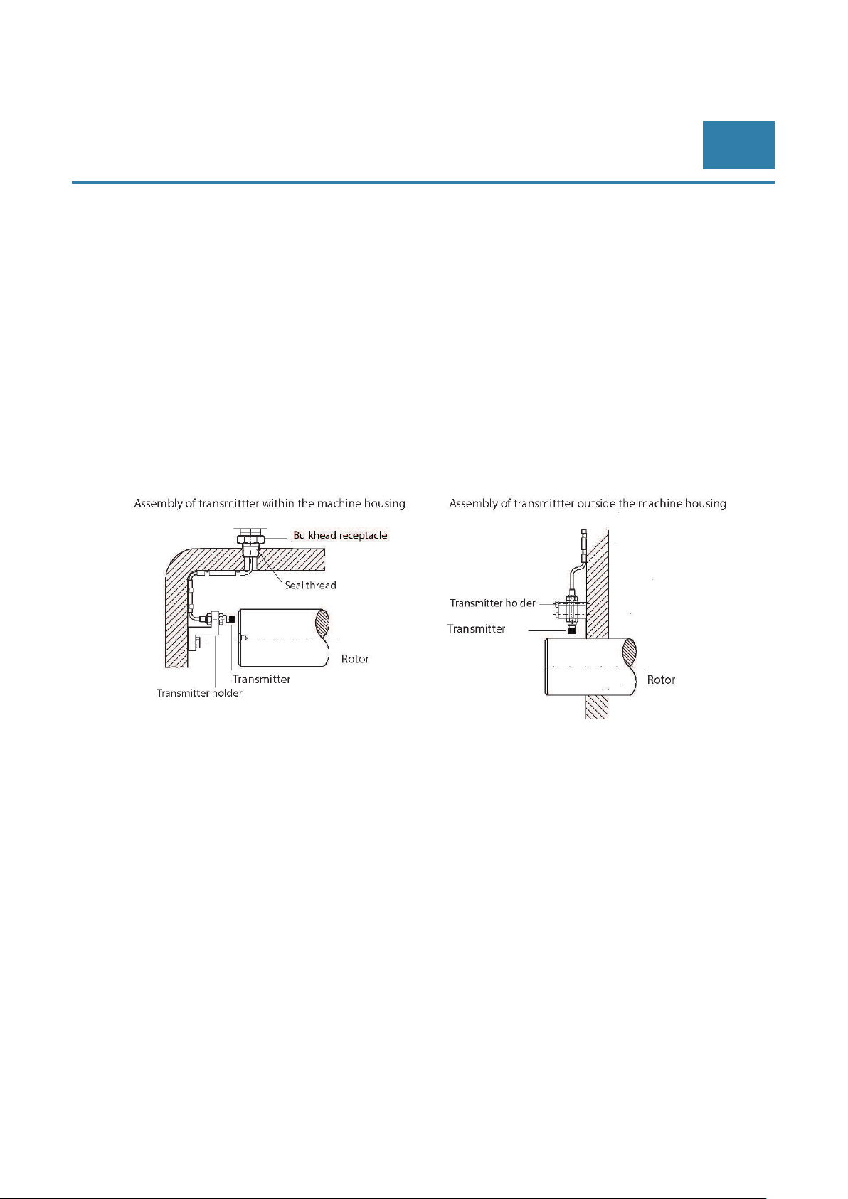
4.1.1 DT-121 and DT-122 forward mountable displacement transmitter
Dependent on the application forward mounting can take place inside a machine, outside a machine
or through the machine housing. To avoid measurement errors, we always recommend using a
suitable holder for the transmitter mounting. For this purpose the transmitter holder is to be mounted
at a location which does not move relative to the measurement object during machine operation.
1. Remove the protective cap on the ceramic tip.
2. Fasten the displacement transmitter with the aid of a transmitter holder suitable for the type of
assembly being undertaken.
3. Position the displacement transmitter so that it is perpendicular to the measuring track.
4. Ensure that the ceramic tip does not touch the measurement object to avoid damage.
5. Adjust the installation position of the displacement transmitter by means of
its dynamic signal output, see Chapter 4.2.
EN
Figure 4-1) Mounting layout for a forward mountable displacement transmitter (schematic diagram)
4.1.2 DT-123 reverse mountable displacement transmitter
The reverse mountable displacement transmitter is preferably mounted by means of a transmitter
holder with adjusting spindle.
• Fasten the displacement transmitter with the aid of a transmitter holder suitable for the type of
assembly being undertaken. We recommend to use the holder AC-3101.
• Adjust the installation position of the displacement transmitter by means of its dynamic signal
output, see Chapter 4.2.
© Brüel & Kjaer Vibro ● C107153002 / v03 ● █ Page 11 of 22
Technical alterations reserved!
Page 12

EN
4.2 Adjusting the installation position of the displacement transmitter
The displacement transmitter must be adjusted while the rotor is stationary. For the measurement
setup the displacement transmitter must be supplied with voltage over the loop-powered interface
(black, white). The target position for the installation position must be known before setting up. To
determine this in advance, for setting up an axial position transmitter for example, the exact location
of the rotor in relation to its possible axial bearing play during operation must be known. To set up a
radial vibration transmitter, it may be necessary to take account of the ‘lift off’ of the rotor during
operation. The target position must be determined in such a way that any contact of the transmitter tip
with the rotor is totally excluded during operation. The GAP voltage to be set must be derived from
the determined target position (see example) for adjustment of the installation position.
Example
DT-12x.AP/0/… measurement of an axial shaft position (nominal measurement range 1.2 mm)
The following variables are known for the concrete application: Full Scale: 1.18 mm for a sensitivity of
8.14 mV/µm or 73.75 µm/mA with regard to the target material used in the application.
The shaft is in the middle position when installing the transmitter. While operation the shaft can move
±0.35 mm in both directions.
The loop output of the AP transmitter is designed in such a way that loop measurement range begins
(4 mA) for a GAP voltage of 2 VDC at the DYN_OUT output. The maximum change in distance, which
represents a loop current of 20 mA, is outputted for this measurement range of nominal 1.2 mm at a
GAP voltage of 11.6 V. This value arises from the nominal sensitivity of 8 mV/µm and the nominal
measurement range (= 2 V + 1.2 mm * 8 mV/µm).
In this example the sensitivity is 8.14 mV/µm. Therefore, in this case, the maximum Full Scale voltage
value of 11.6 V is already achieved for a distance of 1.18 mm (= 2 V + 1.18 mm * 8.14 mV/µm).
In the example it is assumed that the shaft is located in its middle position during installation of the
axial position transmitter. Therefore, it is recommended in this case, to also position the distance
between shaft and transmitter tip for the adjustment of the transmitter installation position to the
middle of its measurement range. This therefore corresponds to the transmitter target position for
installation.
Calculation of the GAP voltage to be set for the installation takes place using the following approach:
The transmitter measurement range begins, as mentioned above, at a GAP voltage of 2 VDC. In this
case the transmitter should be adjusted to the middle of its measurement range. Half of the FS of the
transmitter measurement range is 0.59 mm = ½ * 1.18 mm.
This results in the following value for the required GAP voltage U
(
0,59 )= 2 V + 0,59 mm 8,14
U
= 2 V + 4,8 V
= 6,8 V
for installation:
target
mV
µm
The target position is set up over the dynamic output (blue, red) with the aid of a voltmeter
(see Figure 4-2).
Page 12 of 22
Technical alterations reserved!
█ ©Brüel & Kjaer Vibro ● C107153002 / v03
Page 13
Brüel & Kjaer Vibro │ Instructions
Transmitter Series DT-120
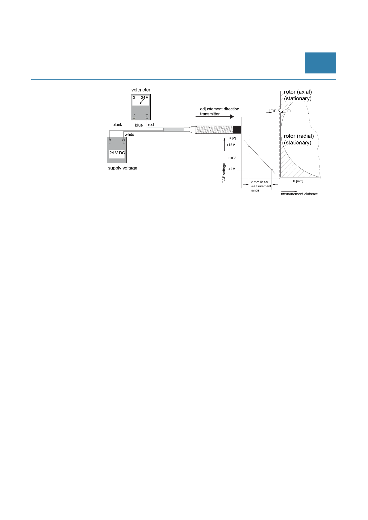
Figure 4-2) Measurement setup for adjustment (axial / radial)
• For the purpose of power supply, the displacement transmitter is connected, for example, to a
process control system over its loop-powered interface.
• The displacement transmitter is pre-mounted in such a way that the distance between the
transmitter tip and the rotor lies outside of its measurement range.
• Switch on the voltage at the loop-powered interface.
• Position the displacement transmitter through careful turning in, in such a way that it comes
into the linear measurement range.
• At the dynamic signal output you obtain the GAP voltage proportional to the measuring
distance in the range of 2 V ... 18 V (linear displacement measurement range). The sensitivity
of the displacement transmitter is nominal 8 mV/µm or 8 V/mm
corresponding mechanical distance (D [mm]) is in the range of min. 0.5 mm to max. 2.5 mm.
• During setup ensure that the transmitter cable is not twisted. The minimum distance of 0.5 mm
to the shaft must be maintained at all times to avoid damaging the ceramic tip (observe the
GAP voltage).
• While observing the dynamic signal output, position the displacement transmitter in such a
way that the GAP voltage corresponding to the target position is set. This guarantees that the
rotor does not leave the linear measurement range at its maximum deflection and the
minimum distance of 0.5 mm is always maintained.
• Fix the displacement transmitter with the locknuts provided (tightening torque 5 Nm). The
displacement transmitter must not be twisted when locking since this would change the target
position and hence the corresponding GAP voltage. Use a suitable screw lock (e.g.
LOCTITE 243 medium-strength) to fix the transmitter in its target position.
• Check the output voltage again.
• Remove the power supply and voltmeter.
• Mount the connecting cable and route it; see the next chapter.
Installation
EN
iii
iv
respectively. The
iii
Cable colours: black, blue, red, white
iv
Regarded under the B&K Vibro standard conditions; use of standard materials
© Brüel & Kjaer Vibro ● C107153002 / v03 ● █ Page 13 of 22
Technical alterations reserved!
Page 14
EN
4.3 Laying of connecting cable
1. Laying the connecting cable.
2. While laying the connecting cable, observe the limitation of the maximum allowable total cable
length of 15 m (including transmitter integrated cable length) for the dynamic signal output.
3. When fixing in place with cable clamps, we recommend using a suitable protective conduit.
4. Earth the cable shield.
For assembly inside the machine:
• Seal the housing opening with the aid of a housing feed-through in such a way that the
medium inside the machine (for example gas or oil) cannot escape to the outside.
We assume no liability for improper installation.
4.4 Electrical connection
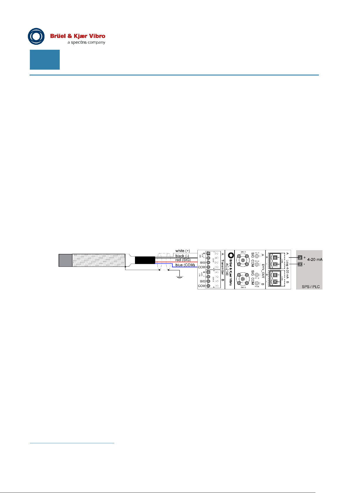
The displacement transmitter is attached over the two conductors of the loop-powered interface to a
subsequent control system (PLC / PCS). We recommend using the connection module AC-2140
(Figure 4-3).
Figure 4-3) Connecting the displacement transmitter to a control system (PLC / PCS)v
v
programmable logic controller (PLC) or a process control system (PCS)
Page 14 of 22
Technical alterations reserved!
█ ©Brüel & Kjaer Vibro ● C107153002 / v03
Page 15
Brüel & Kjaer Vibro │ Instructions
when you perform measurements.
Transmitter Series DT-120
5 Functional test
5.1 Short test
BEWARE!
Risk of injury from moving machine parts. Switch off your machine
Functional test
EN
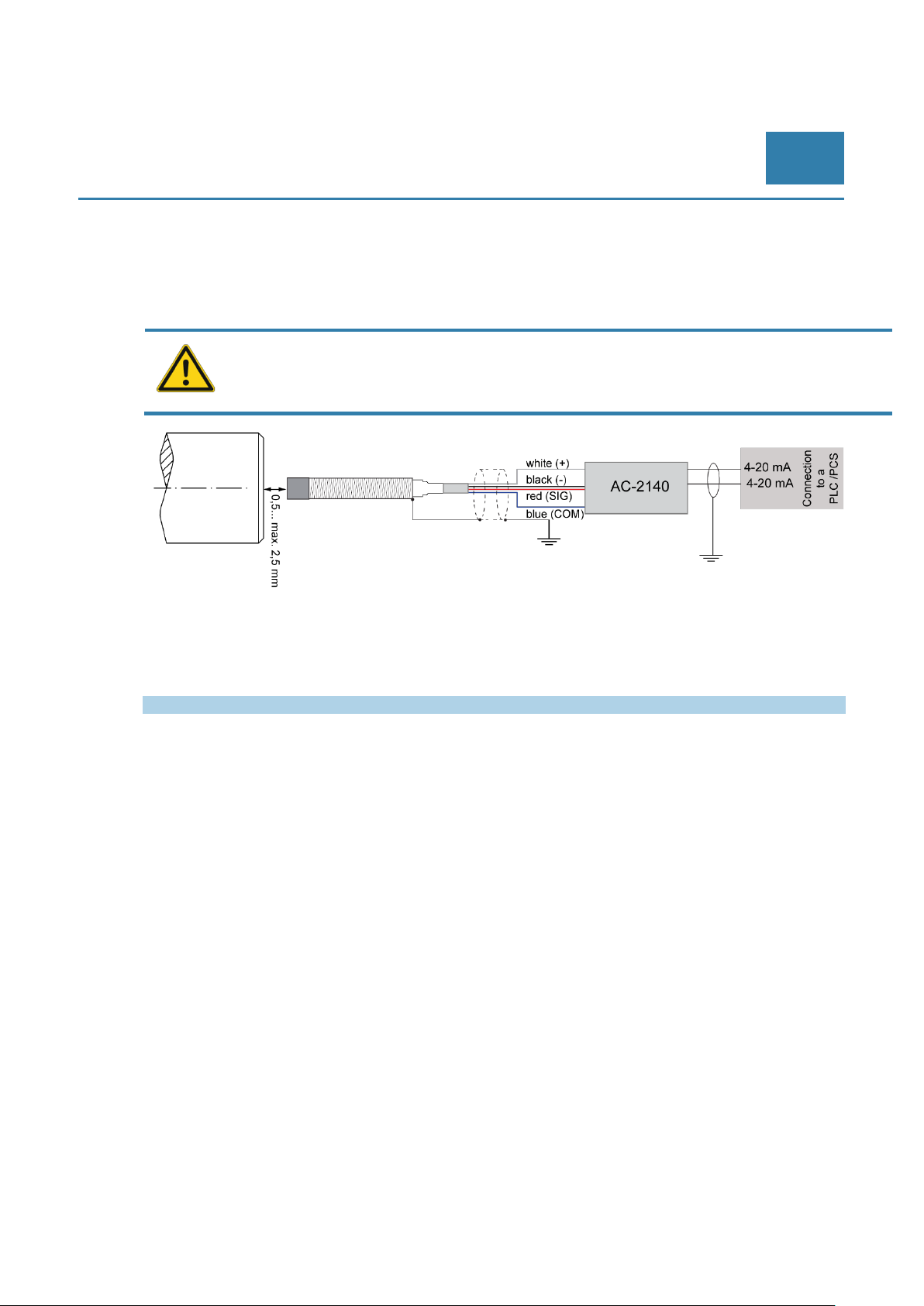
Figure 5-1) Connecting the displacement transmitter to a monitoring system
Once your displacement transmitter is installed you can then check the measurement values. If your
displacement transmitter is in a proper operating state, you will obtain the following values:
Operating voltage UB Operating current IB
-24 VDC ≥ 4.0 mA (DT-12x.RV/x),
4…20 mA (DT-12x.AP/x)
5.2 Troubleshooting
If the measurement results obtained are different, proceed in the sequence we recommend:
Check the output voltage of the dynamic signal output using a voltmeter.
a. Output signal > 18 V, or the signal shifts between two values: the distance is still too large and
therefore outside of the measurement range. In this case reduce the distance until a stable output
signal is obtained.
b. Output signal < 2 V
It is possible that the distance between the target and the ceramic tip is too low.
Adjust the displacement transmitter to a larger distance to the target and check the output signal
again. If the output signal does not change, there is a defect in the displacement transmitter
system.
© Brüel & Kjaer Vibro ● C107153002 / v03 ● █ Page 15 of 22
Technical alterations reserved!
Page 16

EN
BEWARE!
or disassemble the displacement transmitter.
6 Disassembly
Risk of injury from moving machine parts. Switch off your machine when you exchange
To disassemble proceed according to the opposite sequence:
6.1 Exchanging a displacement transmitter
1. Switch off the power for the loop-powered interface.
2. Disassemble the displacement transmitter. Proceed in the reverse order of installation
(see chapter 4.1).
3. Mount a new displacement transmitter. Proceed during assembly and adjustment of the
displacement transmitter as described in Chapter 4.
4. Connect the displacement transmitter to the subsequent control system (see chapter 4.4).
5. Check that all parts are properly connected.
6. Switch on the power for the loop-powered interface.
Page 16 of 22
Technical alterations reserved!
█ ©Brüel & Kjaer Vibro ● C107153002 / v03
Page 17

Brüel & Kjaer Vibro │ Instructions
Transmitter Series DT-120
Technical data
7 Technical data
The following performance data applies under the following standard conditions, unless stated
otherwise:
+18 °C to +27 °C ambient temperature, +24 VDC supply voltage, 250 Ω loop resistance,
dynamic output not connected, material no. 1.7225 (42CrMo4) B&K Vibro reference material, a +6 V
gap voltage; all components are at operating temperature (approx.. 1 hour)
7.1 Series DT–120 non-contacting displacement transmitter
Measurement type
Radial Vibration (RV) Radial shaft vibration in [µm peak-peak]
Axial Position (AP) Axial shaft position in [µm]
Measuring principle Eddy current method
Dynamic characteristics:
Dynamic output
Usage Connection of a potential-free portable
measuring device for system setup or
signal analysis; not designed for continuous
operation
Electrical properties:
Operating voltage +24 VDC (+12 VDC ... +32 VDC)
Current consumption max. 21 mA
Cable length max. 15 m
(including transmitter integrated cable length)
Cable capacity max. 150 pF/m
Mechanical properties
Cable:
Structure 4-core
Cable sheath und colour PTFE, black
Wire assignments
Loop white (+), black (-)
Dynamic output red (+), blue (-)
Diameter Ø 2.9 mm (±0.15 mm)
Core cross-section 0.16 mm²
Length 5 m or 10 m
Transmitter tip:
Material Ceramic
Diameter of the tip Ø 7.2 mm (± 0.1 mm)
Transmitter sleeve
Material Stainless steel (Material no. 1.4404
(X2CrNiMo17-12-2) according to EN10088-3)
Recommended tightening torque 5 Nm
Environment:
Pressure tightness:
Ceramic tip 25 bar
Temperature range
Operating temperature range -40 °C ... +105 °C.
Storage temperature range -55 °C ... +125 °C.
IP range IP68, IP69
EN
© Brüel & Kjaer Vibro ● C107153002 / v03 ● █ Page 17 of 22
Technical alterations reserved!
Page 18
EN
NOTE!
7.2 Environmental requirements
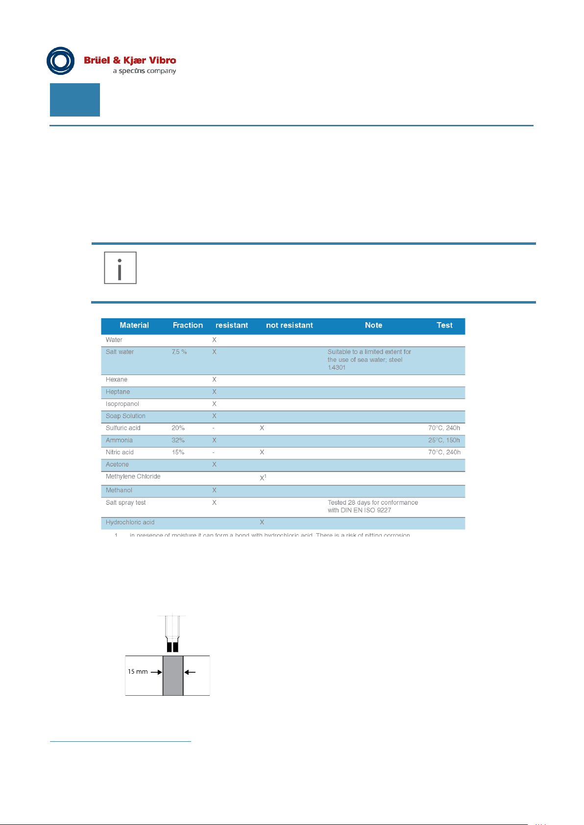
7.2.1 Resistance of the displacement transmitter to different media
If the displacement transmitter is used in media such as water, it can have an impact on the
measurement result. For example, an increase in the electrical conductivity of the surrounding
medium usually causes an increase in the measurement error.
Without additional protective measures, the rear of the displacement transmitter is not
media proof. The values in the following table refer to the ceramic sensor tip only.
7.2.2 Properties of the measuring track
The material characteristic of the measurement object change the static and dynamic measurements.
In order to obtain repeatable and traceable measurements, we recommend to adjust the whole
measurement loop to the respective shaft material and the corresponding system sensitivity.
The measuring track must be at least 15 mm wide, demagnetised
and free of scratches and cavities. The following values must be
observed and maintained to obtain meaningful measurements:
• Roughness R
• Roughness depth R
Please observe the axial movement of the shaft, too.
Figure 7-1) Width of the measuring track
vi
for large areas of unevenness (2 x 2 mm)
Page 18 of 22
Technical alterations reserved!
█ ©Brüel & Kjaer Vibro ● C107153002 / v03
≤ 3.6
a
< 5 μmvi
z
Page 19
Brüel & Kjaer Vibro │ Instructions
NOTE!
Ceramic tip
Distance to shaft
Ceramic tip flush
Required minimum
Distance to shaft
Required minimum
Distance to the
Displacement
Transmitter Series DT-120
Technical data
EN
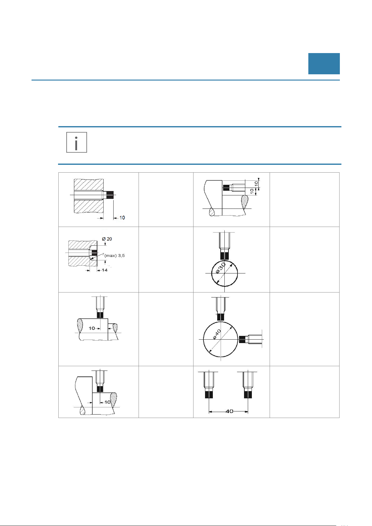
7.2.3 The required clearances and minimum distances for displacement transmitters
The clearances and minimum distances specified below must be strictly observed when installing the
transmitter.
If these clearances and minimum distances must be lowered for design reasons, consult
with Brüel & Kjær Vibro beforehand.
protruding
end
shoulder,
displacement
transmitter parallel to
electrically conductive
material
shaft diameter for a
displacement
transmitter
shaft diameter for two
displacement
transmitters mounted
at 90° angle
© Brüel & Kjaer Vibro ● C107153002 / v03 ● █ Page 19 of 22
Technical alterations reserved!
shaft shoulder
parallel to
electrically
conductive
material
transmitters arranged
in parallel
Page 20

EN
7.2.4 Calibration
Calibration allows one to determine the sensitivity of the transmitter system in relation to a given
material. This requires recording of a characteristic curve for the material using the DT-120
displacement transmitter:
1. Connect the displacement transmitter as described in the measurement setup (Figure 4-2)
and align perpendicular to the suitable material sample.
2. Position the displacement transmitter to a small distance voltage U
out and note the voltage U
3. Increase the distance D in steps of 0.25 mm (D
associated voltages (U
is achieved.
4. Calculate the local sensitivities S
5. The sensitivity S of the transmitter system results from the arithmetic mean of the calculated
local sensitivities S
= 2.5 ... 3.5 V and read
1
and the measurement distance (D1) in the unit [mm].
1
) and read out and note it together with the
x
) in the unit [V]. Repeat this step until a distance voltage Ux > 15 VDC
x
using the formula:
x
=
.
x
[
mV/µm
]
.
We recommend performing calibration with the aid of our static calibration device AC-126. There is
also the option to send in a suitable sample of the material to have a calibration certificate created.
Calculation of the 20 mA Full Scale value from the transmitter calibration
Based on the determined sensitivity S, the Full Scale value @ 20 mA, which is needed for conversion
of the loop current values into measurement values, can now be calculated.
Measurement of the axial position
Calculation of the current AP Full Scale value is done by multiplication of the nominal measurement
range of the AP transmitter by the quotient from the nominal sensitivity of 8 mV/µm or 203.2 mV/mil
and the sensitivity obtained from the calibration, with reference to the target material used:
Measurement of the radial vibration
Calculation of the current RV Full Scale value is done by multiplication of the nominal measurement
range of the RV transmitter by the quotient from the nominal sensitivity of 8 mV/µm or 203.2 mV/mil
and the sensitivity obtained from the calibration, with reference to the target material used:
(
20 ) =
(
20 ) =
Page 20 of 22
Technical alterations reserved!
█ ©Brüel & Kjaer Vibro ● C107153002 / v03
Page 21

Brüel & Kjaer Vibro │ Instructions
Transmitter Series DT-120
8 Disposal
Dispose of the devices, cables or displacement transmitters after use in an environmentally friendly
manner according to the applicable national regulations.
WEEE Reg. No. DE 69572330
Disposal
EN
© Brüel & Kjaer Vibro ● C107153002 / v03 ● █ Page 21 of 22
Technical alterations reserved!
Page 22

Contact
Brüel & Kjaer Vibro GmbH
Leydheckerstrasse10
64293 Darmstadt
Germany
Tel: +49 6151 428-0
Fax: +49 6151 428-1000
Transmitter Series DT-120 ● C107153002 / v03 ● Brüel & Kjaer Vibro ● Technical alterations reserved!
 Loading...