

Page 1
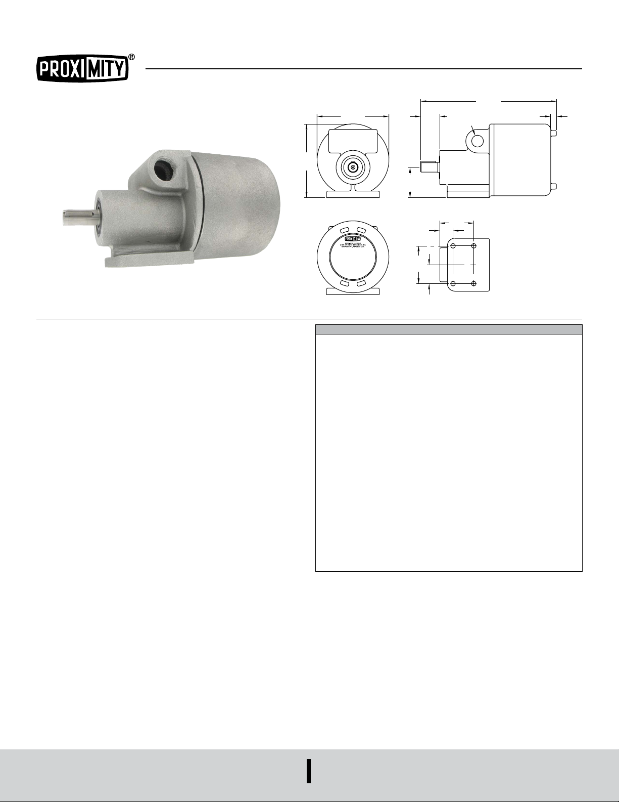
Series DSS Direct-Contact Speed Switch
REAR VIEW
MOUNTING HOLE PLAN
Specications - Installation and Operating Instructions
4-7/8
[123.83]
ø4-3/4
[120.65]
1-17/64
[32.03]
2
[50.8]
3/4˝ NPT PIPE TAP
8-63/64
[228.09]
BOTH SIDES
Bulletin E-17
3/8
[9.53]
The Series DSS Direct-Contact Speed Switch is a compact switch designed to
include all mechanical and electronic components in one housing. It will produce an
output signal at a predetermined speed which may be either over-speed, under-speed
or zero-speed. Rugged, heavy-duty construction combined with solid state electronics
and photo-electric technology makes this one of the most advanced motion detectors
available. Series DSS protects all valuable rotating equipment including belt conveyors,
bucket elevators, rotary feeders or screw conveyors. It operates in a clockwise or
counter-clockwise direction and mounts in any position.
FRONT VIEW SIDE VIEW
7/8
[22.23]
2-1/2
[63.50]
1-1/4
[31.75]
SPECIFICATIONS
Ambient Temperature Range: 14°F to 131°F (-10°C to +55°C).
Max. Operating Temperature: DSS-E: Class T6: 185°F (85°C).
Enclosure: Aluminum with screw cover.
Enclosure Rating: DSS-W: NEMA 3S, 4 and 4X. DSS-E: NEMA 3S, 4 and 4X,
NEMA 7: Class I groups C and D, NEMA 9: Class II groups F and G, class III.
Switch Type: DPDT.
Electrical Rating: 3A @ 120/240 VAC, 1/10 Hp @120/240 VAC.
Electrical Connections: Screw terminal.
Conduit Connections: (2) 3/4˝ female NPT.
Mounting Orientation: Any.
Set Point Adjustment: Adjustment screw.
Power Requirements: 105-135 VAC, 50/60 Hz, 210-250 VAC, 50/60 Hz; or 24
VAC/DC depending on model.
Power Consumption: 3 W.
Repeatability: 2% max. at constant voltage and temperature.
Pick-up Point: 3 speed ranges at which relay will energize: Low: 0.1 to 10 RPM;
Medium: 1 to 100 RPM; High: 10 to 1000 RPM.
Signal Point: Speed at which relay will de-energize. Recommended to be 15-20%
lower than pick-up point.
Start-up Delay: Adjustable up to 45 s.
Radial Load on Input Shaft: 125 lbs max.
End Thrust on Input Shaft: 100 lbs max.
Rotation: Either clockwise or counter-clockwise.
Driving torque: 1˝/lb max. Shaft: 5/8˝ diameter with 3/16˝ x 7/8˝ key; Weight: 5 lbs
(2.3 kg).
Compliance: cUL, UL.
2-1/4
[57.15]
DWYER INSTRUMENTS, INC.
P.O. BOX 373 • MICHIGAN CITY, INDIANA 46360, U.S.A.
Phone: 219-879-8000
Fax: 219-872-9057
www.dwyer-inst.com
e-mail: [email protected]
Page 2
OPERATING PRINCIPLE
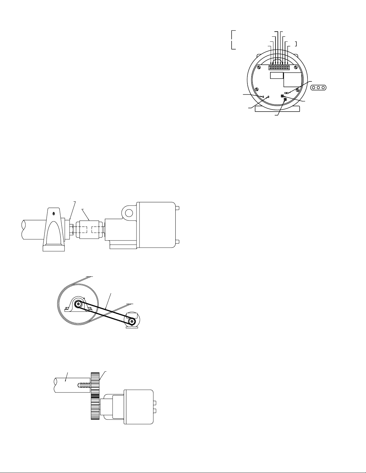
CUSTOMER’S SHAFT WITH
CUSTOMER’S SHAFT WITH
CONCENTRIC STUB SHAFT
NORMALLY OPEN 2
NORMALLY CLOSED 2
The Series DSS Motion Switch senses motion by means of a precision metal disc
mounted on the input shaft. This disc generates measurable light pulses by a series of
slots on its periphery, which rotate past an infrared light source. A photo-electric sensor
monitors the series of light pulses and converts them to digital electronic signals.
Solid state circuitry then analyzes the digital signals and activates or deactivates the
output relay at the pre-set speed. Field adjustment of the signal set point is easily
accomplished by means of an adjustment screw on the electronics. For under-speed
sensing, the signal point is set below the normal operating speed of the unit. The
output relay will then de-energize if the speed drops below the signal point. For overspeed sensing, the pick-up point is set above the normal operating speed. The output
relay will energize if the speed exceeds the pick-up point. Zero-speed sensing can be
accomplished by turning the adjustment screw to its minimum setting. The output relay
will then de-energize when the shaft speed of the unit approaches zero.
INSTALLATION
LOCATION AND MOUNTING
The Series DSS motion switch can be mounted for operation in any position. The
surface to which the switch is afxed should be as at and as smooth as possible.
Bearing brackets and shim plate sets can be used to mount the unit directly to the
pillow block supporting a shaft. On installations where vibration conditions are not
extreme, use 1/4˝ diameter machine bolts with lock washers through the four mounting
holes in the base of the switch. (Mounting bolts and lock washers are not furnished
with the switch.) If vibration conditions are extreme, use of a doweling is recommended
through two mounting holes in the switch base. The switch should be mounted as
axially in line, and/or parallel as possible to the existing shaft, which is to drive the
switch. The Series DSS motion switch can be driven by one of the following means:
1. Direct connection through a coupling (preferred means). Note: Switch should be
concentric with the mating shaft. If stub is used, it must be concentric with the main
shaft. If a stub shaft is required, we suggest the use of a 5/8˝ stub shaft. Use with a
split or exible type coupling.
CONCENTRIC STUB SHAFT
FLEXIBLE COUPLING
Figure 1: Suggested coupling arrangement, side view
WIRING
USE ONLY SOLID
CONDUCTORS OF
14 AWG OR SMALLER
GREEN L.E.D. INDICATES
RELAY ENERGIZED
YELLOW L.E.D.
INDICATES PULSES
NORMALLY OPEN 1
NORMALLY CLOSED 1
COMMON 1
SPEED SET POINT
COMMON 2
L2
LINE VOLTAGE
L1
SPEED RANGE
LHM
TIME DELAY
Figure 4: Electronics view
Remove end cap to expose terminals and pick-up speed adjustment screw. Wire input
power from source to terminals L1 & L2. Be certain to use the provided ground screw.
The output of the Series DSS is a DPDT relay. There are two sets of output contacts.
Each set includes normally open, normally closed and common. As a result, the unit
can be used to control two separate circuits such as a motor starter and a signal light.
CONDUIT INSTALLATION
Use only hubs of suitable sizes that are UL/CSA approved for WATERTIGHT use.
Install per the hub manufacturer’s instructions. Be sure the location selected will
provide adequate wire bending space.
SIGNAL SET POINT
FOR USE AS AN UNDER-SPEED SWITCH
Select the speed range required by changing the switch to LOW for 0.1 to 10
RPM, MEDIUM for 1 to 100 RPM and HIGH for 10 to 1000 RPM. Turn the set point
potentiometer to the counter-clockwise stop. With motion present on the input shaft
and at normal operating RPM, the yellow LED should blink. The green LED should turn
on indicating that the output relay is energized. Slowly turn the set point adjustment
screw clockwise until the output relay de-energizes. (A “click” will occur at this point.)
Back up until the output relay energizes. Thus, when speed drops below the set point,
the green LED should turn off indicating that the output relay is de-energized. If the
normal operating speed of the input shaft exceeds 10 RPM for the LOW, 100 RPM
for the MEDIUM or 1000 RPM for the HIGH, the unit should be adjusted as follows.
Turn the set point adjustment screw clockwise until it reaches the stop. When the
speed drops below 10 RPM for the HIGH, the relay will energize. Note: Typically, the
motor contact is wired in series with one of the NO output contacts and an alarm is
wired with one of the NC output contacts.
A V-Belt drive is not as desirable because of possible slippage.
COG BELT (TIMING) OR
ROLLER CHAIN DRIVE
Figure 2: Cog belt drive (timing) or roller chain drive:
SPUR GEARS
Figure 3: Suggested spur gear arrangement (top view)
FOR USE AS A ZERO-SPEED SWITCH
Select the HIGHEST speed range by changing the switch to HIGHEST for 0.1 to 10
RPM. Turn the set point potentiometer to the counter-clockwise stop. This will give a
set point of 0.1 RPM. Thus, when the speed drops below 0.1 RPM, the output relay
will de-energize. Note: Wiring should be the same as for under-speed applications.
TIME DELAY SETTING
The Series DSS motion switch has a start-up delay that is adjustable up to 45 seconds.
This setting should be set, depending on the application and the length of time it takes
for the conveyor to reach its normal operating RPM. This time delay takes effect upon
power-up of the Series DSS after shutdown. AC power to the Series DSS must be
interrupted for timer to be reset. This delay only effects start-up, avoiding nuisance
start-up alarms.
Page 3

TROUBLESHOOTING
Problem Solution
• No pulses from yellow LED
• Relay is not energized or de-energized
• Alarm sounds when equipment is
started
• Alarm sounds when equipment is
started
• Equipment is not shut off when
expected
MAINTENANCE
Upon nal installation of the Series DSS Direct-Contact Speed Switch, no routine
maintenance is required. A periodic check of the system calibration is recommended.
The Series DSS is not eld serviceable and should be returned if repair is needed
(eld repair should not be attempted and may void warranty). Be sure to include a
brief description of the problem plus any relevant application notes. Contact customer
service to receive a return goods authorization number before shipping.
• Check power supply. Make sure input
shaft is turning.
• Check power supply. When expected.
(I.e. green LED not on: Make sure
input shaft is turning. Or off when
expected.) Check for proper set point.
Check for proper speed setting. (LOW,
MEDIUM or HIGH)
• Check startup delay setting. Check for
proper connections between alarm and
relay. AC power must be interrupted for
alarm to reset.
• Check power supply. Check for proper
connections between alarm and relay.
• Check power supply. Check for proper
connections between control circuit
and relay.
Page 4

Printed in U.S.A. 8/22 FR# 443493-00 Rev. 2 ©Copyright 2022 Dwyer Instruments, Inc.
DWYER INSTRUMENTS, INC.
P.O. BOX 373 • MICHIGAN CITY, INDIANA 46360, U.S.A.
Phone: 219-879-8000
Fax: 219-872-9057
www.dwyer-inst.com
e-mail: [email protected]
 Loading...