

Page 1
User’s Guide
Shop online at
omega.com
e-mail: [email protected]
For latest product manuals:
www.omegamanual.info
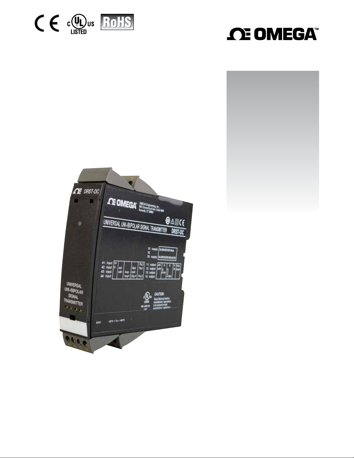
DRST-DC
Universal Uni-/Bipolar
Signal Transmitter
Page 2

U.S.A.
Headquarters:
omega.com [email protected]
Servicing North America:
Omega Engineering, Inc.
800 Connecticut Ave. Suite 5N01 Norwalk, CT 06854
Toll-Free: 1-800-826-6342 (USA & Canada only) Customer
Service: 1-800-622-2378 (USA & Canada only)
Service: 1-800-872-9436 (USA & Canada only)
Tel: (203) 359-1660 Fax: (203) 359-7700
e-mail: [email protected]
Engineering
For Other Locations Visit omega.com/worldwide
The information contained in this document is believed to be correct, but OMEGA accepts no liability for any errors it contains, and reserves
the right to alter specifications without notice.
Page 3

Universal Uni-/bipolar
gnal transmitter
si
DRST-DC
Table of contents
Warning ................................................................................................ 4
Symbol identification .................................................................................... 4
Safety instructions ...................................................................................... 5
How to demount system DRST-DC........................................................................... 6
When front LED flashes red or DRSL-DISPLAY shows AO.ER ............................................ 6
Advanced features ...................................................................................... 7
Application ............................................................................................. 7
Mounting / installation / programming .................................................................... 7
Applications ............................................................................................ 8
DRSL-DISPLAY / programming front ............................................................... 9
Mounting / demounting the DRSL-DISPLAY . . . . . . . . . . . . . . . . . . . . . . . . . . . . . . . . . . . . . . . . . . . . . . . . . . . . . . . . . . . . . . . 9
Order ................................................................................................... 10
Accessories ............................................................................................. 10
Electrical specifications .................................................................................. 10
Configurable input error indication and input limits ........................................................ 14
Square root function. .................................................................................... 17
DRSL-DISPLAY readout of input error detection and signal ”outside range”.............................. 19
Connections ............................................................................................ 20
Block diagram ........................................................................................... 21
Configuration / operating the function keys ............................................................... 22
Routing diagram ........................................................................................ 24
Routing diagram, advanced settings (ADV.SET) ............................................................ 28
Help text overview ...................................................................................... 30
Document history ....................................................................................... 32
3
Page 4
GENERAL
HAZARD-
OUS
VOLTAGE
Warning
This device is designed for connection to hazardous electric voltages. Ignoring this warning can result in
severe personal injury or mechanical damage.
To avoid the risk of electric shock and fire, the safety instructions of this guide must be observed and
the guidelines followed. The specifications must not be exceeded, and the device must only be applied
as described in the following.
Prior to the commissioning of the device, this installation guide must be examined carefully.
Only qualified personnel (technicians) should install this device. If the equipment is used in a manner not
specified by the manufacturer, the protection provided by the equipment may be impaired.
Warning
Until the device is fixed, do not connect hazardous voltages to the device. The following operations
should only be carried out on a disconnected device and under ESD safe conditions:
General mounting, connection and disconnection of wires.
Troubleshooting the device.
Repair of the device and replacement of circuit breakers must be done by Omega Engineering only.
CAUTION
Warning
Do not open the front plate of the device as this will cause damage to the connector for the display /
programming front DRSL-DISPLAY.
T
is device contains no DIP-switches or jumpers.
h
SYSTEM DRST-DC must be mounted on a DIN rail according to DIN EN 60715.
Symbol identification
Triangle with an exclamation mark: Warning / demand. Potentially lethal situations. Read the manual
before installation and commissioning of the device in order to avoid incidents that could lead to
personal injury or mechanical damage.
The CE mark proves the compliance of the device with the essential requirements of the directives.
The double insulation symbol shows that the device is protected by double or reinforced insulation.
4
Page 5

Safety instructions
Definitions
Hazardous voltages have been defined as the ranges: 75 to 1500 Volt DC, and 50 to 1000 Volt AC.
Technicians are qualified persons educated or trained to mount, operate, and also trouble-shoot technically correct and in
accordance with safety regulations.
Operators, being familiar with the contents of this manual, adjust and operate the knobs or potentiometers during normal
operation.
Receipt and unpacking
Unpack the device without damaging it and check whether the device type corresponds to the one ordered. The packing
should always follow the device until this has been permanently mounted.
Environment
Avoid direct sun light, dust, high temperatures, mechanical vibrations and shock, and rain and heavy moisture. If necessary,
heating in excess of the stated limits for ambient temperatures should be avoided by way of ventilation.
The device must be installed in pollution degree 2 or better.
Mounting
Only technicians, who are familiar with the technical terms, warnings, and instructions in the manual and who are able to
follow these, should connect the device. Should there be any doubt as to the correct handling of the device, please contact
your local distributor or, alternatively,
Mounting and connection of the device should comply with national legislation for mounting of electric materials, i.e. wire
ection, protective fuse, and location.
cross s
Descriptions of input / output and supply connections are shown in the block diagram and side label.
The following apply to fixed hazardous voltages-connected devices:
The max. size of the protective fuse is 10 A and, together with a power switch, it should be easily accessible and close to
the device. The power switch should be marked with a label indicating that it will switch off the voltage
he device.
to t
Year of manufacture can be taken from the first two digits in the serial number.
UL installation requirements
Use 60/75°C copper conducters only
For use only in pollution degree 2 or better
Max. ambient temperature . . . . . . . . . . . . . . . . . . . . . . . . . . . . . . 60°C
Max. wire size. . . . . . . . . . . . . . . . . . . . . . . . . . . . . . . . . . . . . . AWG 26-14
UL file number . . . . . . . . . . . . . . . . . . . . . . . . . . . . . . . . . . . . . E248256
Calibratio
During calibration and adjustment, the measuring and connection of external voltages must be carried out according to the
specifications of this manual. The technician must use tools and instruments that are safe to use.
n and Adjustment
Normal operation
Operators are only allowed to adjust and operate devices that are safely fixed in panels, etc., thus avoiding the danger of
personal injury and damage. This means there is no electrical shock hazard, and the device is easily accessible.
Cleaning
When disconnected, the device may be cleaned with a cloth moistened with distilled water.
Liability
To the extent the instructions in this manual are not strictly observed, the custom er cannot advance a demand against
Omega Engineering that would otherwise exist according to the concluded sales agreement.
5
Page 6
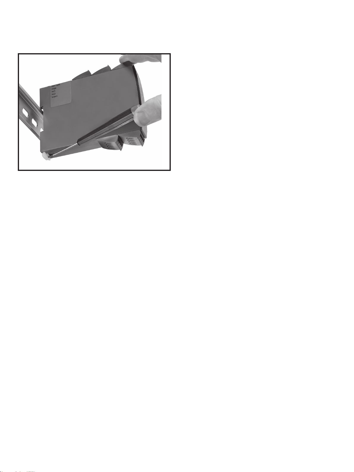
How to demount system DRST-DC
Picture 1:
The device is detached from the DIN rail by moving the bottom lock down.
When front LED flashes red or DRSL-DISPLAY shows AO.ER
DRST-DC is designed with a high safety level. Therefore, the device continuously measures the output current. If "S4-20"
The
is selected during configuration, and output current drops to 0 mA, the DRSL-DISPLAY will indicate "AO.ER" and the front LED
will turn red. (A 0 mA output can be caused by an open output loop). The error mode can be reset by power cycling the device
or stepping through the menu.
6
Page 7

Universal uni-/bipolar signal transmitter
DRST-DC
• Measures uni-/bipolar DC current and voltage signals
• Passive/active current output and buffered voltage output
• Extremely good signal dynamics for spans from 25 mV to 300 VDC
• Programming, process monitoring and diagnostics via DRSL-DISPLAY
• Fast < 20 ms response time and excellent < 0.05% accuracy
• Configurable input limits
• Universally powered by 21.6…253 VAC / 19.2...300 VDC
Application
• Fast < 20 ms response time for measuring signals produced by torque, position, current & acceleration sensors.
• User configurable bipolar or unipolar I/O means DRST-DC is suitable for nearly any DC voltage or current conversion.
• Freely programmable between ±300 VDC and ±100 mA.
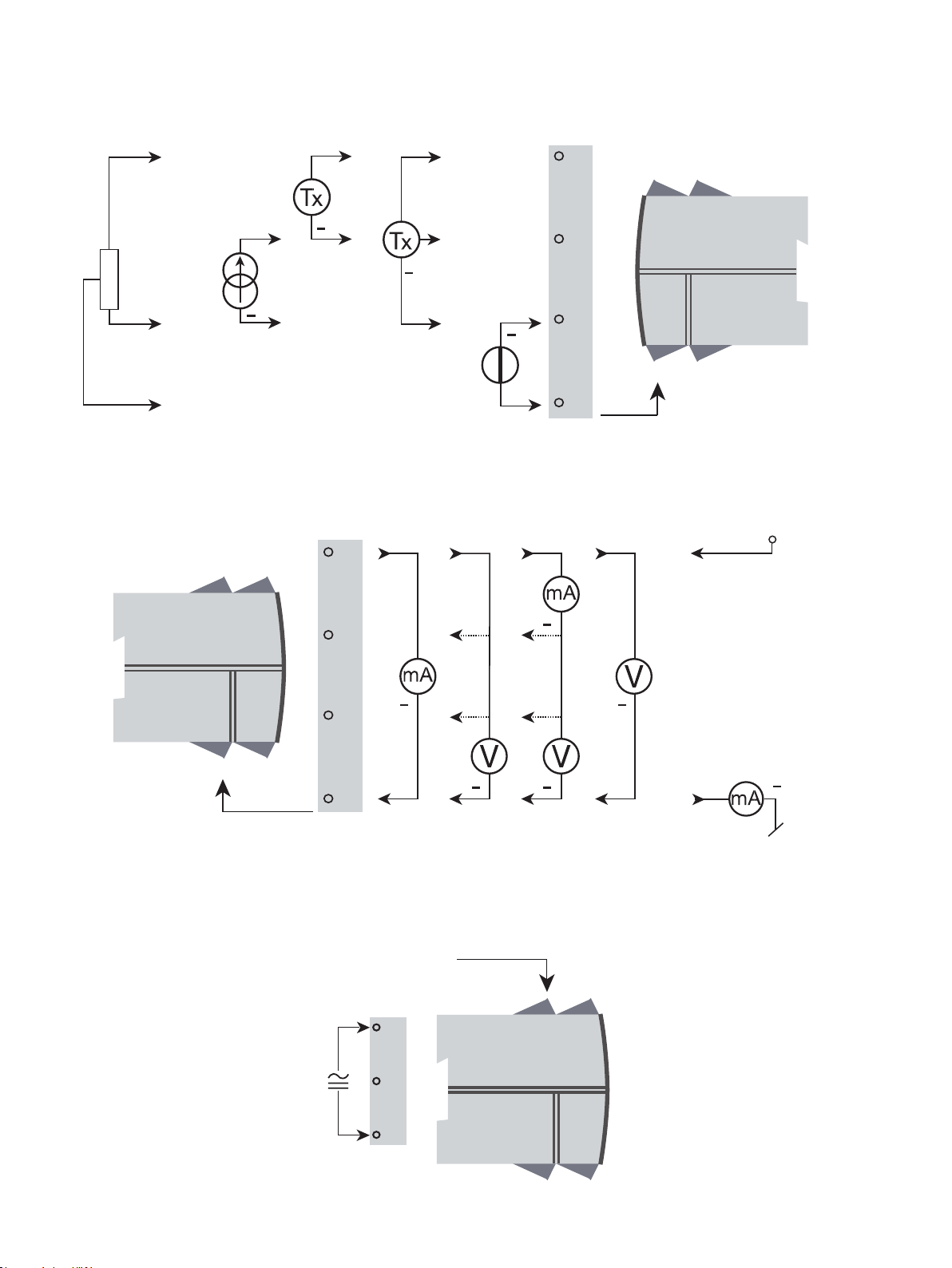
• The excitation source allows measurement of a 2-wire or 3-wire transmitter, or a potentiometer.
• The active or passive I/O makes the DRST-DC perfect for power matching current loops.
• Converts narrow bipolar inputs to wide bipolar or unipolar outputs, e.g., ±1 volt input = ±10 volt or 4...20 mA output.
• Selectable direct or inverse I/O makes the DRST-DC suitable for proportional control applications.
• Configurable input limits control the output value for increased safety.
• ±20 VDC buffered voltage output for controlling devices like the PVG 32 valve (6...18 VDC).
• Connection for both passive and active inputs and outputs.
• The detachable DRSL-DISPLAY provides enhanced diagnostics.
Technical characteristics
• The latest analog and digital techniques are used to obtain maximum accuracy and immunity to interference.
• Possibility of output safety readback by selecting S4...20 mA output.
• The current output can drive up to 1000 Ohms, with an adjustable response time of 0.0…60.0 seconds.
• Exceptional mA output load stability of < 0.001% of span / 100 Ohm.
• Meets the NAMUR NE21 recommendations, ensuring high accuracy in harsh EMC environments.
• Meets the NAMUR NE43 recommendations, allowing the control system to easily detect a sensor error.
• Each unit is tested to a high 2.3 kVAC, 3-port galvanic isolation level.
• Excellent signal to noise ratio of > 60 dB.
Mounting / installation / programming
• Very low power consumption means units can be mounted side by side without an air gap – even at 60°C ambient
perature.
tem
• Configuration, monitoring, 2-point process calibration and more are accomplished using either the DRSL- detachable display
or the DRST-CM detachable digital communication enabler.
• All programming can be password-protected.
7
Page 8
Input signals:
Potentio-
meter
Applications
Current 3-wire Tx2-wire Tx Voltage
+
+
44
100 mA
(±)
Output signals:
+
12
14
13
300 V
(±)
Current & voltage
+
10 V
1 V
+
+
+
10 V
1 V
+
43
42
41
Buffered
voltage
+
+ V supply
3.5...28.8 V
2-wire
(±)
}
Power connection:
8
11
21.6...253 VAC
or
19.2...300 VDC
33
32
31
Page 9
OK
4501
3
4
DRSL-DISPLAY & DRST-CM / programming front
Functionality
The simple and easily understandable menu structure and the explanatory help texts guide you
effortlessly and automatically through the configuration steps, thus making the product very easy to
use. Functions and configuration options are described in the section ”Configuration / operating the
function keys”.
Application
• Communications interface for modification of operational parameters in DRST-DC.
Can be moved from one DRST-DC device to another and download the configuration of the first unit
•
to subsequent units.
• When mounted in the process, the display shows process values and device status.
Technical characteristics
• LCD display with 4 lines:
Line 1 (H=5.57 mm) shows the scaled process value - OK or error.
Line 2 (H=3.33 mm) shows the selected engineering unit.
Line 3 (H=3.33 mm) shows analog output or TAG no.
Line 4 shows status for communication and signal trending.
• Programming access can be blocked by assigning a password. The password is saved in the device
in order to ensure a high degree of protection against unauthorized modifications to the
configuration.
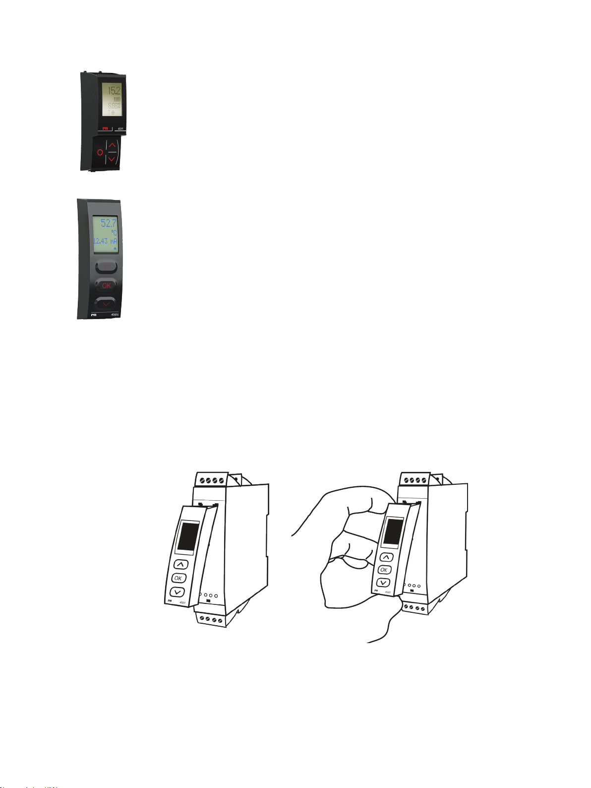
Mounting / demounting the DRSL-DISPLAY & DRST-CM
1: Insert the tabs of the DRSL-DISPLAY & DRST-CM the holes at the top of the device.
2: Hinge the DRSL-DISPLAY & DRST-CM down until it snaps into place.
Demounting of the DRSL-DISPLAY & DRST-CM
3: Push the release button on the bottom of the DRSL-DISPLAY & DRST-CM and hinge the the DRSL-DISPLAY & DRSTCM out and up.
4: With the DRSL-DISPLAY & DRST-CM hinged up, remove from holes at the top of the device.
1
2
4
3
9
Page 10

Order
DRST-DC = Universal uni-/bipolar signal
transmitter
Accessories
DRSL-DISPLAY = Display / programming front
DRST-CM = Communication enabler
Electrical specifications Environmental conditions:
Operating temperature . . . . . . . . . . . . . . . . . . . . . . . . . . . . . . . . -20°C to +60°C
Storage temperature . . . . . . . . . . . . . . . . . . . . . . . . . . . . . . . . . -20°C to +85°C
Calibration temperature. . . . . . . . . . . . . . . . . . . . . . . . . . . . . . . . 20...28°C
Relative humidity . . . . . . . . . . . . . . . . . . . . . . . . . . . . . . . . . . . < 95% RH (non-cond.)
Protection degree . . . . . . . . . . . . . . . . . . . . . . . . . . . . . . . . . . . IP20
Installation in pollution degree 2 & measurement / overvoltage category II.
Mechanical specifications:
Dimensions (HxWxD) . . . . . . . . . . . . . . . . . . . . . . . . . . . . . . . . . 109 x 23.5 x 104 mm
Dimensions (HxWxD) w/DRSL-DISPLAY. . . . . . . . . . . . . . . . . . . . . . . 109 x 23.5 x 116 / 131 mm
Weight approx. . . . . . . . . . . . . . . . . . . . . . . . . . . . . . . . . . . . . . 250 g
Weight incl. DRSL-DISPLAY(approx.) . . . . . . . . . . . . . . . . . . . . . . . . . 285 g / 350 g
DIN rail type. . . . . . . . . . . . . . . . . . . . . . . . . . . . . . . . . . . . . . . DIN EN 60715 - 35 mm
Wire size. . . . . . . . . . . . . . . . . . . . . . . . . . . . . . . . . . . . . . . . . 0.13...2.08 mm
AWG 26...14 stranded wire
Screw terminal torque. . . . . . . . . . . . . . . . . . . . . . . . . . . . . . . . . 0.5 Nm
Common electrical specifications:
Supply voltage, universal. . . . . . . . . . . . . . . . . . . . . . . . . . . . . . . 21.6...253 VAC, 50...60 Hz
or 19.2...300 VDC
Max. required power. . . . . . . . . . . . . . . . . . . . . . . . . . . . . . . . . . ≤ 2.5 W
Max. power dissipation . . . . . . . . . . . . . . . . . . . . . . . . . . . . . . . . ≤ 2.0 W
Isolation voltage - test . . . . . . . . . . . . . . . . . . . . . . . . . . . . . . . . 2.3 kVAC
Isolation voltage - working. . . . . . . . . . . . . . . . . . . . . . . . . . . . . . 250 VAC (reinforced) / 500 VAC (basic)
Programming . . . . . . . . . . . . . . . . . . . . . . . . . . . . . . . . . . . . . . Communication enabler DRST-CM /
Programming front DRSL-DISPLAY
Signal dynamics, input / output . . . . . . . . . . . . . . . . . . . . . . . . . . . 24 bit / 18 bit
Signal / noise ratio. . . . . . . . . . . . . . . . . . . . . . . . . . . . . . . . . . . > 60 dB
Bandwidth (3 dB) . . . . . . . . . . . . . . . . . . . . . . . . . . . . . . . . . . . > 40 Hz
Response time (0...90%, 100...10%) . . . . . . . . . . . . . . . . . . . . . . . . < 20 ms
Auxiliary supplies:
2-wire loop supply (terminal 43, 44). . . . . . . . . . . . . . . . . . . . . . . . > 16 V @ 20 mA
3-wire loop supply (terminal 42, 44) . . . . . . . . . . . . . . . . . . . . . . . . > 18...< 28 V @ 23...0 mA
Loop supply limitation (terminal 42, 44) . . . . . . . . . . . . . . . . . . . . . . 27...35 mA avg., < 80 mA peak
Reference voltage . . . . . . . . . . . . . . . . . . . . . . . . . . . . . . . . . . . 2,5V ±0.5%
Reference voltage, load. . . . . . . . . . . . . . . . . . . . . . . . . . . . . . . . 0...15 mA
Current limit, reference voltage . . . . . . . . . . . . . . . . . . . . . . . . . . . < 60 mA
2
/
10
Page 11
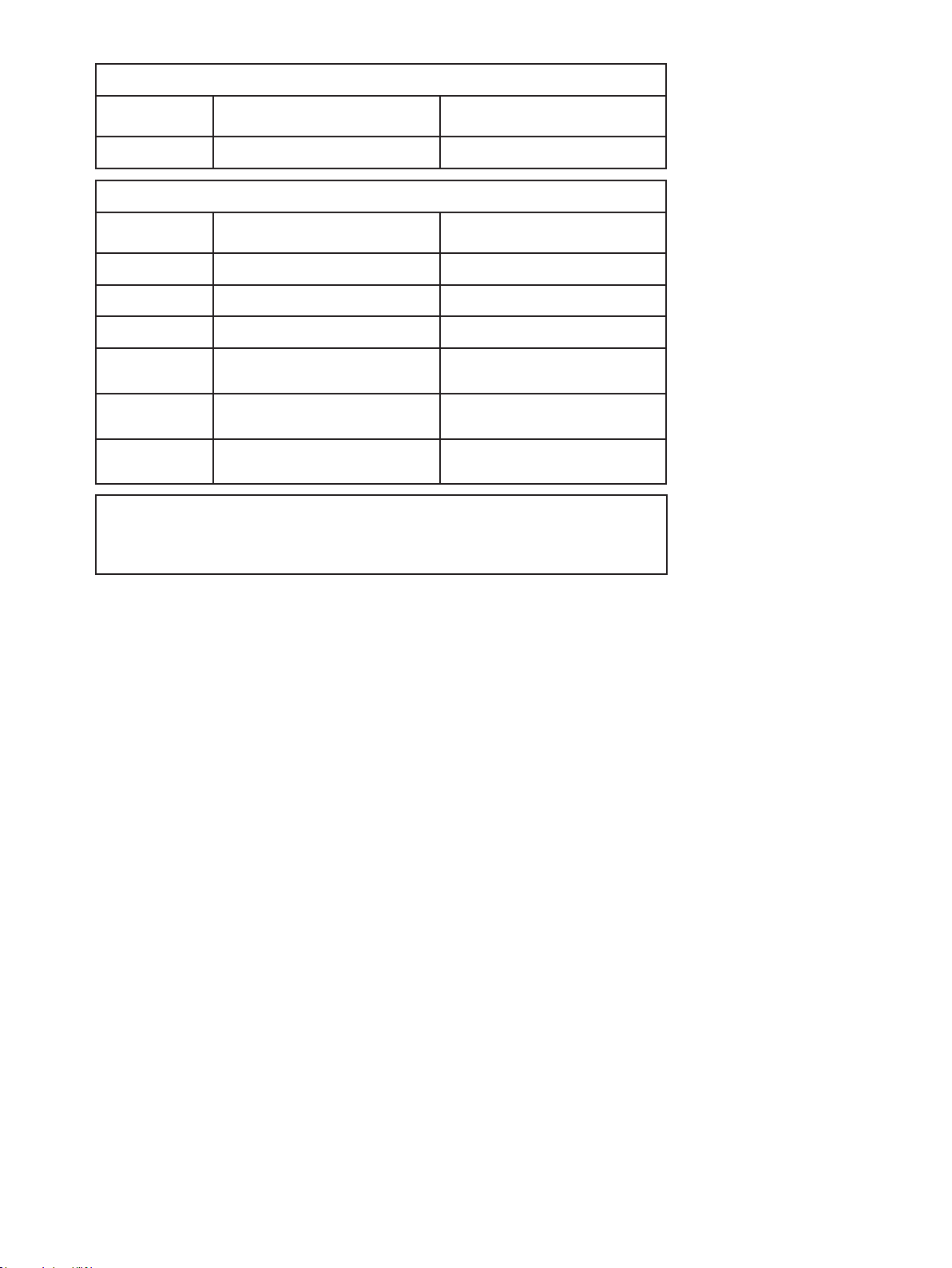
Accuracy, the greater of general and basic values:
General values*
Input type Absolute accuracy Temperature coecient
All ≤ ±0.05% of span ≤ ±0.01% of span / °C
Basic values
Type Basic accuracy Temperature coecient
Current input ±0.334 µA ±0.067 µA / °C
Voltage input ±8.33 µV ±1.67 µV / °C
Current output ±1.33 µA ±0.266 µA / °C
Buered
voltage output ±267 µV ±53.4 µV / °C
Shunted voltage
output (±1 V) ±267 µV ±53.4 µV / °C
Shunted voltage
output (±10 V) ±1333 µV ±0.267 µV / °C
EMC - immunity influence. . . . . . . . . . . . . . . . . . . . . . . . . < ±0.5% of span
Extended EMC immunity:
NAMUR NE 21, A criterion, burst . . . . . . . . . . . . . . . . . . . . < ±1% of span
Conducted emission, class A . . . . . . . . . . . . . . . . . . . . . . . 150 kHz...10 MHz
of span = of selected standard range
* For custom input and output ranges, values for accuracy, temperature coecient and EMC performance are valid with a
maximum input oset of 50% and a maximum output oset of 20%.
Input specifications:
Current input:
Signal range. . . . . . . . . . . . . . . . . . . . . . . . . . . . . . . . . . . . . . . ±100 mA
Programmable measurement ranges . . . . . . . . . . . . . . . . . . . . . . . . 0...1, 0...5, 1...5, 0...20, 4...20,
±1, ±5, ±10, ±20, ±50, ±100 mA
Custom configurable signal range. . . . . . . . . . . . . . . . . . . . . . . . . . ±100 mA
Min. span . . . . . . . . . . . . . . . . . . . . . . . . . . . . . . . . . . . . . . . . 0.5 mA
Input resistance . . . . . . . . . . . . . . . . . . . . . . . . . . . . . . . . . . . . Nom. 20 Ω + PTC 10 Ω
Input voltage drop, nom. . . . . . . . . . . . . . . . . . . . . . . . . . . . . . . . 0.6 V @ 20 mA
Voltage input:
Signal range. . . . . . . . . . . . . . . . . . . . . . . . . . . . . . . . . . . . . . . ±300 VDC
Programmable measurement ranges . . . . . . . . . . . . . . . . . . . . . . . . 0...0.1, 0...1, 0.2...1, 0...2.5,
0...5, 1...5, 0...10, 2...10, 0...100, 0...300,
±0.1, ±1, ±2.5, ±5, ±10, ±100, ±300 V
Custom configurable signal range. . . . . . . . . . . . . . . . . . . . . . . . . . ±300 V
Min. span . . . . . . . . . . . . . . . . . . . . . . . . . . . . . . . . . . . . . . . . 25 mV
Input resistance, nom.
> 2.5 V input . . . . . . . . . . . . . . . . . . . . . . . . . . . . . . . . . . . . . 3 MΩ nom.
≤ 2.5 V input . . . . . . . . . . . . . . . . . . . . . . . . . . . . . . . . . . . . . > 10 MΩ
Potentiometer input:
3-wire potentiometer input (terminal 41, 42 & 44) . . . . . . . . . . . . . . . 0...100%
Reference voltage (terminal 42, 44) . . . . . . . . . . . . . . . . . . . . . . . . 2.5 V
Calibration resistance . . . . . . . . . . . . . . . . . . . . . . . . . . . . . . . . . 5 kΩ
Min. potentiometer resistance . . . . . . . . . . . . . . . . . . . . . . . . . . . . 200 Ω
11
Page 12

Configurable input limits:
Error detection . . . . . . . . . . . . . . . . . . . . . . . . . . . . . . . . . . . . . Enable / disable
Configurable input limits, low:
VOLT . . . . . . . . . . . . . . . . . . . . . . . . . . . . . . . . . . . . . . . . . . 'Minimum selected input’ to -300 V
CURR. . . . . . . . . . . . . . . . . . . . . . . . . . . . . . . . . . . . . . . . . . ‘Minimum selected input’ to -100 mA
POTM . . . . . . . . . . . . . . . . . . . . . . . . . . . . . . . . . . . . . . . . . 'Minimum selected input' to 0%
Configurable input limits, high:
VOLT . . . . . . . . . . . . . . . . . . . . . . . . . . . . . . . . . . . . . . . . . . ‘Maximum selected input’ to 300 V
CURR. . . . . . . . . . . . . . . . . . . . . . . . . . . . . . . . . . . . . . . . . . ‘Maximum selected input’ to 100 mA
POTM . . . . . . . . . . . . . . . . . . . . . . . . . . . . . . . . . . . . . . . . . 'Maximum selected input' to 100%
Input limit low/high, error indication levels:
UP . . . . . . . . . . . . . . . . . . . . . . . . . . . . . . . . . . . . . . . . . . . See tables on pages 15-16
DOWN . . . . . . . . . . . . . . . . . . . . . . . . . . . . . . . . . . . . . . . . . See tables on pages 15-16
ZERO. . . . . . . . . . . . . . . . . . . . . . . . . . . . . . . . . . . . . . . . . . See tables on pages 15-16
NONE . . . . . . . . . . . . . . . . . . . . . . . . . . . . . . . . . . . . . . . . . See tables on pages 15-16
Hysteresis. . . . . . . . . . . . . . . . . . . . . . . . . . . . . . . . . . . . . . . . 0.5% of ‘Max. input’
Error detection release delay . . . . . . . . . . . . . . . . . . . . . . . . . . . . 0.7...0.8 s
Output specifications
Common specifications current output:
All standard and custom ranges can be selected as Direct or Inverted action or V-Function.
Active / passive output range . . . . . . . . . . . . . . . . . . . . . . . . . . . . ±23 mA / 0...23 mA
Programmable standard ranges . . . . . . . . . . . . . . . . . . . . . . . . . . . 0...5, 1...5, 0...10, 2...10, 0...20, 4...20, S4-20 mA
±5, ±10, ±20 mA
Custom configurable output range . . . . . . . . . . . . . . . . . . . . . . . . . ±20 mA
Min. span . . . . . . . . . . . . . . . . . . . . . . . . . . . . . . . . . . . . . . . . 4 mA
Load, max.. . . . . . . . . . . . . . . . . . . . . . . . . . . . . . . . . . . . . . . . ≤ 1000 Ω / ± 20 V @ ±20 mA
Current limit. . . . . . . . . . . . . . . . . . . . . . . . . . . . . . . . . . . . . . . ≤ 28 mA (unipolar) / ±28 mA (bipolar)
Load stability . . . . . . . . . . . . . . . . . . . . . . . . . . . . . . . . . . . . . . 0.001% of span / 100 Ω
Response time, programmable. . . . . . . . . . . . . . . . . . . . . . . . . . . . 0.0...60.0 s
Output limitation at outside range . . . . . . . . . . . . . . . . . . . . . . . . . See tables on pages 15-16
Passive 2-wire mA:
Programmable ranges . . . . . . . . . . . . . . . . . . . . . . . . . . . . . . . . . 0...20 and 4...20 mA
Direct or Inverted action
External 2-wire loop supply . . . . . . . . . . . . . . . . . . . . . . . . . . . . . 3.5...28.8 V
Voltage output specifications:
All standard and custom ranges can be selected as Direct or Inverted action or V-Function.
Programmable ranges . . . . . . . . . . . . . . . . . . . . . . . . . . . . . . . . . 0/0.2...1, 0/1...5, 0/2...10, ±1, ±5 and ±10 V
Direct or Inverted action
Load, min . . . . . . . . . . . . . . . . . . . . . . . . . . . . . . . . . . . . . . . . > 500 kΩ
Response time, programmable. . . . . . . . . . . . . . . . . . . . . . . . . . . . 0.0...60.0 s
Output limitation at outside range . . . . . . . . . . . . . . . . . . . . . . . . . See tables on pages 15-16
Shunted voltage output:
Signal range. . . . . . . . . . . . . . . . . . . . . . . . . . . . . . . . . . . . . . . ± 1.2 V / ± 12 V
Programmable standard ranges . . . . . . . . . . . . . . . . . . . . . . . . . . . 0...1, 0...2.5, 0...5, 1...5, 0...10, 2...10 V
±1, ±2.5, ±5, ±10 V
Custom configurable output range . . . . . . . . . . . . . . . . . . . . . . . . . ±10 V
Min. span . . . . . . . . . . . . . . . . . . . . . . . . . . . . . . . . . . . . . . . . 0.8 V
Load, min. . . . . . . . . . . . . . . . . . . . . . . . . . . . . . . . . . . . . . . . . > 500 kΩ
12
Page 13

Buffered voltage output:
Signal range. . . . . . . . . . . . . . . . . . . . . . . . . . . . . . . . . . . . . . . ± 23 V
Programmable standard ranges . . . . . . . . . . . . . . . . . . . . . . . . . . . 0...1, 0.2...1, 0...2.5, 0...5, 1...5,
0...10, 2...10, 0...20, 4...20 V
±1, ±2.5, ±5, ±10, ±20 V
Custom configurable output range . . . . . . . . . . . . . . . . . . . . . . . . . ±20 V
Min. span . . . . . . . . . . . . . . . . . . . . . . . . . . . . . . . . . . . . . . . . 0.8 V
Current limit. . . . . . . . . . . . . . . . . . . . . . . . . . . . . . . . . . . . . . . < 50 mA
Load, min. . . . . . . . . . . . . . . . . . . . . . . . . . . . . . . . . . . . . . . . . > 2 kΩ
Observed authority requirements:
EMC. . . . . . . . . . . . . . . . . . . . . . . . . . . . . . . . . . . . . . . . . . . . 2014/30/EU
LVD . . . . . . . . . . . . . . . . . . . . . . . . . . . . . . . . . . . . . . . . . . . . 2014/35/EU
RoHS . . . . . . . . . . . . . . . . . . . . . . . . . . . . . . . . . . . . . . . . . . . 2011/65/EU
Approvals:
c UL us, Standard for Safety . . . . . . . . . . . . . . . . . . . . . . . . . . . . . UL 508 / C22.2 No. 14
13
Page 14
Configurable input error indication and input limits
Extended working range
Configurable input error detection
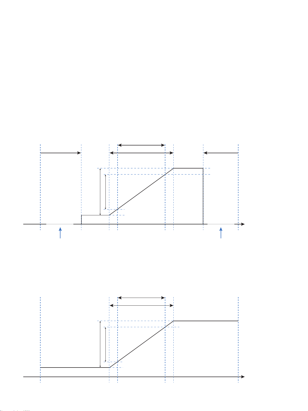
To increase system safety and integrity, users can program a high and low input error detection level. Input signals outside
the selected error indication levels will cause the output of the device to go to the programmed error state. The error is
indicated in display line 1 as IN.ER and at the same time the backlight flashes.
The two configurable input error detection levels can be set and enabled individually, just as it is possible to individually set
the output error indication for each of the two detection levels. This allows users to differentiate process faults, broken input
wires, etc.
Available output error states for each of the two detection levels are: UP, DOWN, ZERO and NONE.
Output error indication uses the error states defined by NAMUR NE43 for 4...20 mA output span, and for all other output
spans equivalent output error indications are used (see tables on pages 15-16).
Example - 4..20 mA output span and both high and low configurable input error limit enabled with output error
indication set to ZERO:
Device
Min. input
Error current
Output error current can be
individually set to:
ZERO: 0 mA
UP: 23 mA
DOWN: 3.5 mA
DISABLED: No error indication,
output limited to 3.8 mA
Configurable input
limit, low
Example - Error indication set to NONE:
Extended working range
Normal measuring range
Extended measuring range
Normal range
4.0 mA
3.8 mA
Output error indication = ZERO
Configurable input
limit, high
20.5 mA
20.0 mA
Error current
Output error current can be
individually set to:
ZERO: 0 mA
UP: 23 mA
DOWN: 3.5 mA
DISABLED: No error indication,
output limited to 20.5 mA
Device
Max. input
Input:
mA, mV etc.
14
‘Min. selected
input’ - 15%
Normal measuring range
Extended measuring range
Normal range
4.0 mA
3.8 mA
Output error indication = NONE
‘Max. selected
input’ + 15%
20.5 mA
20.0 mA
Input:
mA, mV etc.
Page 15
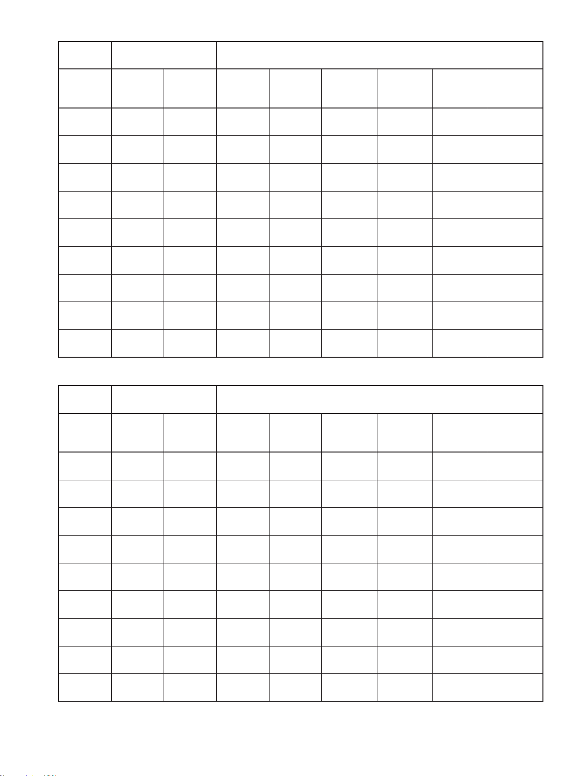
Output limits and error indications – current output:
Output
span
Input error indication
disabled
Output limit
low
Output limit
high
Configurable input limits low or high enabled
Output limit
low
Output limit
high
Output error
indication,
UP
Output error
indication,
DOWN
Output error
indication,
ZERO
4...20 mA 0 mA 23 mA 3.8 mA 20.5 mA 23 mA 3.5 mA 0 mA
0...20 mA 0 mA 23 mA 0 mA 20.5 mA 23 mA 0 mA 0 mA
2...10 mA 0 mA 11.5 mA 0.195 mA 10.25 mA 11.5 mA 0 mA 0 mA
0...10 mA 0 mA 11.5 mA 0 mA 10.25 mA 11.5 mA 0 mA 0 mA
0...5 mA 0 mA 5.75 mA 0 mA 5.125 mA 5.75 mA 0 mA 0 mA
1...5 mA 0 mA 5.75 mA 0.975 mA 5.125 mA 5.75 mA 0.875 mA 0 mA
±5 mA -5.75mA 5.75 mA -5.125 mA 5.125 mA 5.75 mA 5.75 mA 0 mA
±10 mA -11.5 mA 11.5 mA -10.25 mA 10.25 mA 11.5 mA -11.5 mA 0 mA
±20 mA -23 mA 23 mA -20.5 mA 20.5 mA 23 mA -23 mA 0 mA
Output error
indication,
NONE
No error
indication
No error
indication
No error
indication
No error
indication
No error
indication
No error
indication
No error
indication
No error
indication
No error
indication
Output limits and error indications – shunted voltage output:
Output
span
Input error indication
disabled
Output limit
low
Output limit
high
Configurable input limits low or high enabled
Output limit
low
Output limit
high
Output error
indication,
UP
Output error
indication,
DOWN
0...1 V 0 V 1.15 V 0 V 1.025 V 1.15 V 0 V 0 V
0.2...1 V 0 V 1.15 V 0.195 V 1.025 V 1.15 V 0.175 V 0 V
0...5 V 0 V 5.75 V 0 V 5.125 V 5.75 V 0 V 0 V
1...5 V 0 V 5.75 V 0.975 V 5.125 V 5.75 V 0.875 V 0 V
0...10 V 0 V 11.5 V 0 V 10.25 V 11.5 V 0 V 0 V
2...10 V 0 V 11.5 V 1.95 V 10.25 V 11.5 V 1.75 V 0 V
±1 V -1.15 V 1.15 V -1.025 V 1.025 V 1.15 V -1.15 V 0 V
±5 V -5.75 V 5.75 V -5.125 V 5.125 V 5.75 V -5.75 V 0 V
±10 V -11.5 V 11.5 V -10.25 V 10.25 V 11.5 V -11.5 V 0 V
Output error
indication,
ZERO
Output error
indication,
NONE
No error
indication
No error
indication
No error
indication
No error
indication
No error
indication
No error
indication
No error
indication
No error
indication
No error
indication
15
Page 16
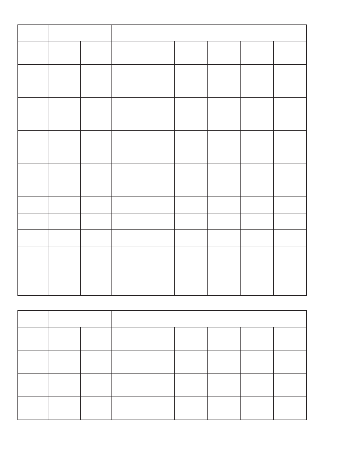
Output limits and error indications – buffered voltage output:
Output
span
Input error indication
disabled
Output limit
low
Output limit
high
Configurable input limits low or high enabled
Output limit
low
Output limit
high
Output error
indication,
UP
Output error
indication,
Output error
indication,
DOWN
0...1 V 0 V 1.15 V 0 V 1.025 V 1.15 V 0 V 0 V
0.2...1 V 0 V 1.15 V 0.195 V 1.025 V 1.15 V 0.175 V 0 V
0...2.5 V 0 V 2.875 V 0 V 2.5625 V 2.875 V 0 V 0 V
0...5 V 0 V 5.75 V 0 V 5.125 V 5.75 V 0 V 0 V
1...5 V 0 V 5.75 V 0.975 V 5.125 V 5.75 V 0.875 V 0 V
0...10 V 0 V 11.5 V 0 V 10.25 V 11.5 V 0 V 0 V
2...10 V 0 V 11.5 V 1.95 V 10.25 V 11.5 V 1.75 V 0 V
0...20 V 0 V > 21 V 0 V 20.5 V > 21 V 0 V 0 V
4... 20 V 0 V > 21 V 3.8 V 20.5 V > 21 V 3.5 V 0 V
±1 V -1.15 V 1.15 V -1.025 V 1.025 V 1.15 V -1.15 V 0 V
±2.5 V -2.875 V 2.875 V -2.5625 V 2.5625 V 2.875 V -2.875 V 0 V
±5 V -5.75 V 5.75 V -5.125 V 5.125 V 5.75 V -5.75 V 0 V
±10 V -11.5 V 11.5 V -10.25 V 10.25 V 11.5 V -11.5 V 0 V
±20 V < -21 V > 21 V -20.5 V 20.5 V > 21 V < -21 V 0 V
ZERO
Output error
indication,
NONE
No error
indication
No error
indication
No error
indication
No error
indication
No error
indication
No error
indication
No error
indication
No error
indication
No error
indication
No error
indication
No error
indication
No error
indication
No error
indication
No error
indication
Output limits and error indications – custom outputs (applies to both voltage and current outputs):
Output
span
Outputs
starting at
zero
Offset
output
span *)
Bipolar
output
span
Input error indication
disabled
Output limit
low
Output limit
high
‘Max.
0 V / 0 mA
output’*
115%
‘Max.
0 V / 0 mA
output’*
115%
‘Min.
output’*
115%
‘Max.
output’*
115%
Configurable input limits low or high enabled
Output limit
low
0 V / 0 mA
‘Min.
output’*
95%
‘Min.
output’*
102.5%
Output limit
high
‘Max.
output’*
102.5%
‘Max.
output’*
102.5%
‘Max.
output’*
102.5%
Output error
indication,
UP
‘Max.
output’*
115%
‘Max.
output’*
115%
‘Max.
output’*
115%
Output error
indication,
0 V / 0 mA 0 V / 0 mA
‘Min.
output’*
87.5%
‘Min.
output’*
115%
DOWN
Output error
indication,
ZERO
0 V / 0 mA
0 V / 0 mA
*) An output is considered oset if the span does not include zero or a zero crossing.
16
Output error
indication,
NONE
No error
indication
No error
indication
No error
indication
Page 17
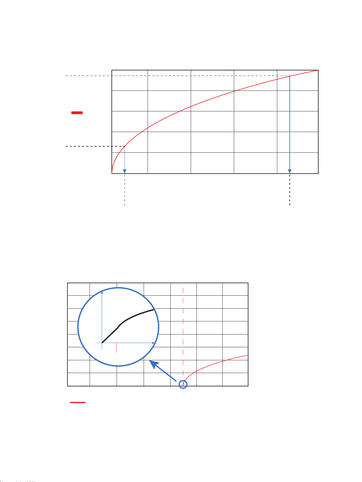
quare root function
S
The DRST-DC features the possibility of configuring a square root relationship between the input and output.
It is possible to use the full square root relationship, or to select a fraction of the square root function, by manually choosing
‘Input min.’ and ‘input max.’ of the square root function, as shown in the figure below:
Output max.
1
0.8
√x
0.6
0.4
Output min.
0.2
Config.
0
min. point
Config.
max. point
0 0.80.60.40.2
Input
x
min.
Low cut-off function:
As a part of the square root function of the DRST-DC is possible to manually configure a low cut-off point. The feature is often
used to suppress noise in the system.
The low cut off point defines a point where the input/output relationship either changes to a linear relationship or the output
is tr
uncated to zero. The two principles are illustrated below:
Input
max.
Linear cut-off:
1.15
1.006
0.863
0.719
0.575
Output range
0.431
0.288
0.144
0
0
sqrt(x)
Output range
0
Low cut-o point
in_min
Input range
0.10
Input range
17
Page 18
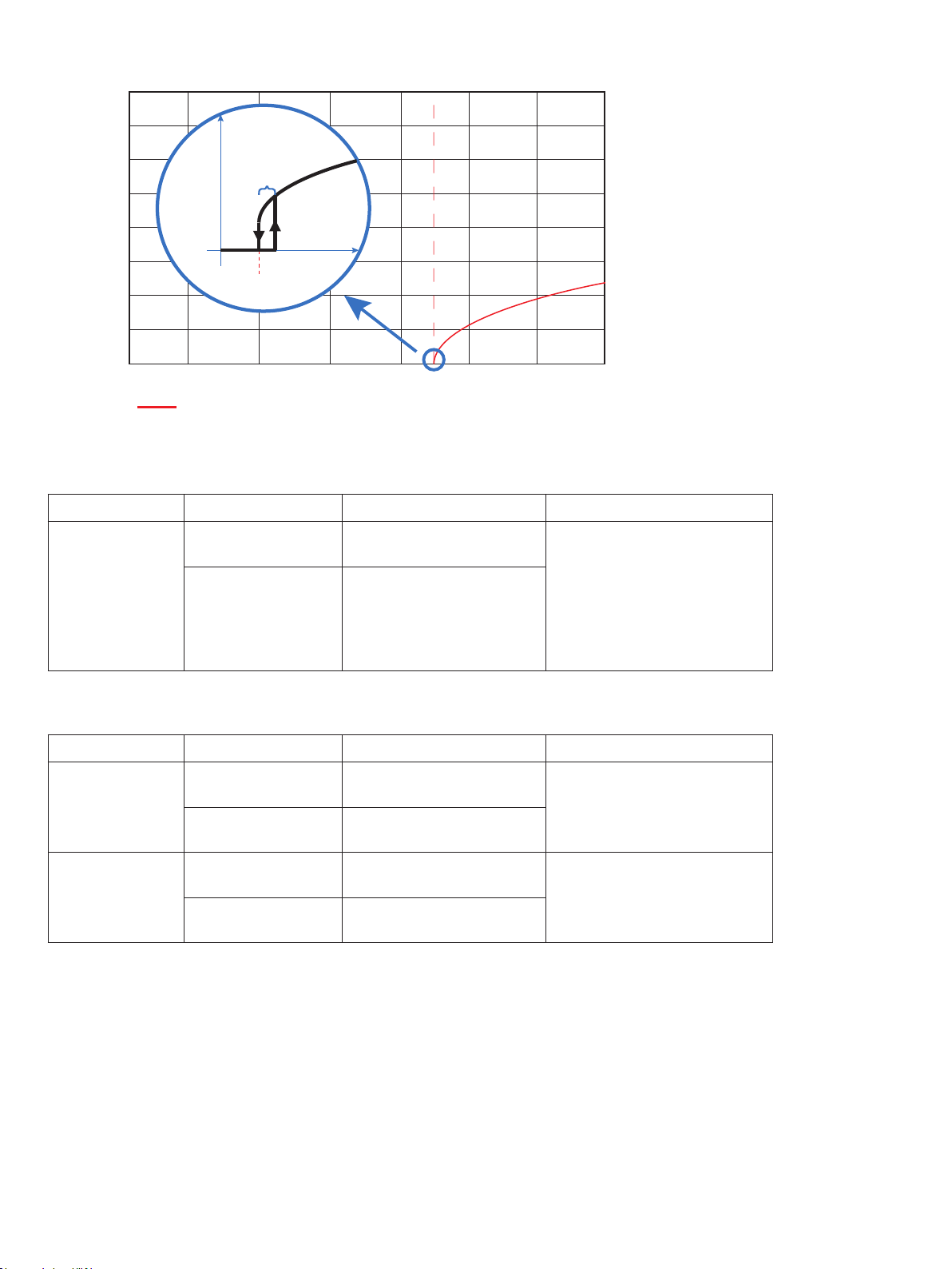
Truncation to zero:
1.15
1.006
0.863
Fixed hysteresis:
0.5% of input
range
in_min
0.719
Output range
0.575
Output range
0.431
0.288
0
0
Input range
Low cut-o point
0.144
0
0.10
sqrt(x)
Input range
Configuration Parameter Specification Condition
Linear cut-off
Low cut-off point
0.0 to 50.0% of
selected input range
0.0 to 50.0% of
selected input range
Independent of square root
settings
Truncation to zero
Fixed hysteresis of 0.5% of
the selected input range
Over range / under range operation:
Configuration Parameter Specification Condition
Normal square root
Input low limit
action
Input high limit
Input low limit
Inverted square
root operation
Input high limit
‘Minimum of selected input
range’
‘Maximum of selected input
range’ + 20%
‘Minimum of selected input
range’ – 20%
‘Maximum of selected input
range’
‘Square root point max.‘
‘Square root point min.‘
‘Square root point max.‘
‘Square root point min.‘
>
<
18
Page 19
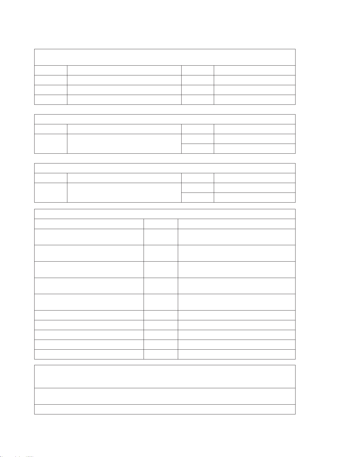
DRSL-DISPLAY & DRST-CM readout of input error detection and signal
”outside range”
Configurable input error detection - readout (IN.ER):
Input Range Readout Limit
CURR All IN.ER See tables on pages 15-16
VOLT All IN.ER See tables on pages 15-16
POTM All IN.ER See tables on pages 15-16
Display readout at ”outside range” limits
Input Range Readout Limit
All All
Display readout below min. / above max. (-1999, 9999):
Input Range Readout Limit
All All
IN.LO Depending on input type
IN.HI Depending on input type
-1999 Display readout <-1999
9999 Display readout >9999
Readout at hardware error
Error search Readout Cause
Check measurement of analog output AO.ER No load on the current output (only S4...20 mA)*
Communications test between
DRSL-DISPLAY and DRST-DC
Configuration error CO.ER Default configuration is loaded
Configuration error CO.ER Invalid configuration**
Check
that saved configuration in DRSL-
DISPLAY matches device
Hardware error RA.ER RAM error*
Hardware error AD.ER A/D converter error*
Hardware error AO.SU Analog output supply error*
Hardware error EF.ER External flash error*
Hardware error IF.ER Internal flash error*
All error indications in the display flash once per second. The help text explains the error. If the error is an
!
input loop error, the display backlight flashes as well - this is acknowledged (stopped) by pushing the 3
button.
Error is acknowledged by either stepping through the basic setup, or by resetting the device power.
*
Some types of errors can only be acknowledged by resetting the device power.
** Error is acknowledged by stepping through the basic setup.
NO.CO Connection error
TY.ER Invalid type or rev. no.
19
Page 20
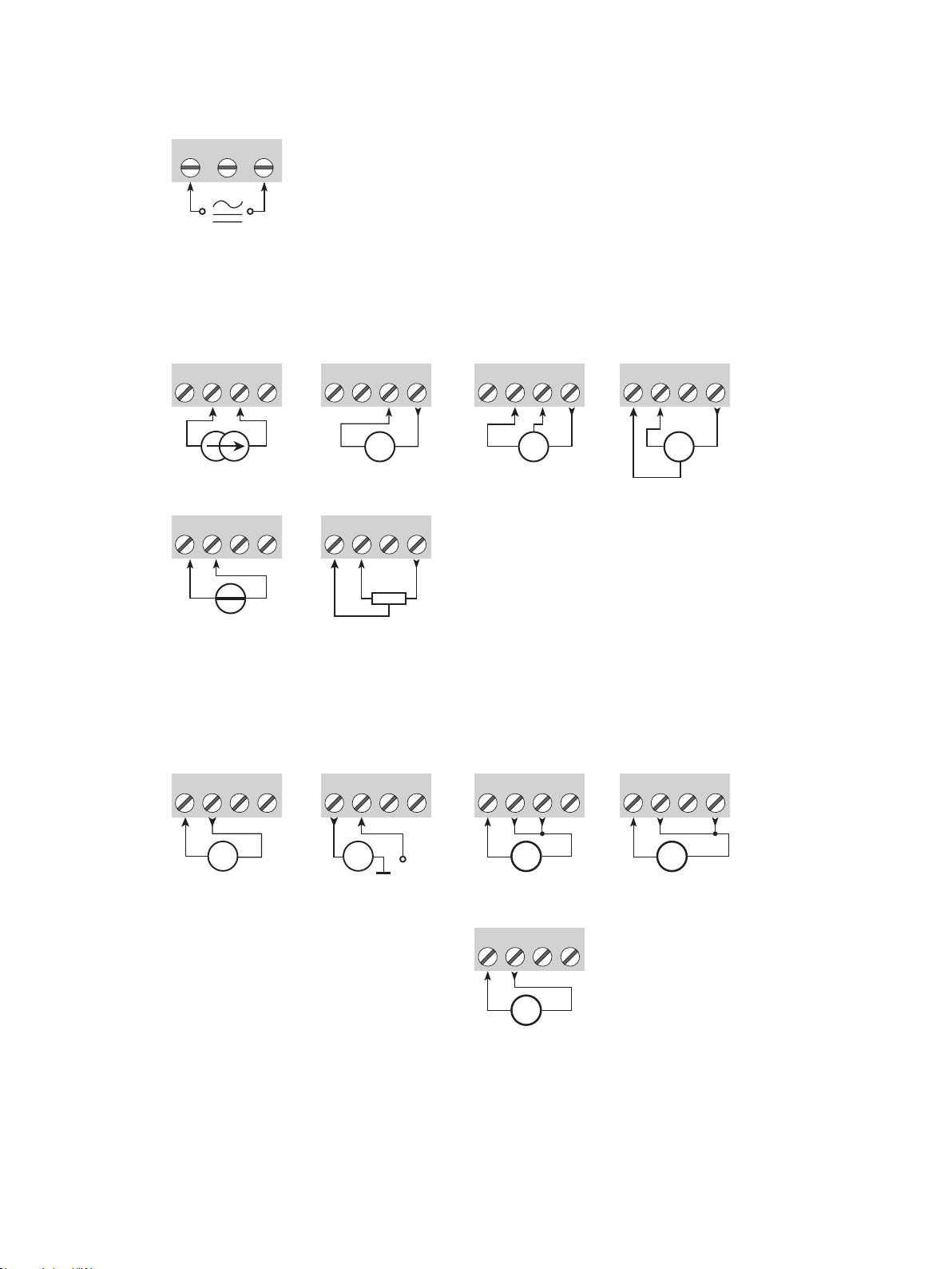
Supply
31 32 33
Connections
Inputs:
3-wire current
transmitter
44 41
4342
-
41
+ -
+
(±)
Voltage Potentiometer
(±)
44
4342
41
Tx
44
4342
+-
44
4342
41
4342
Tx
Outputs:
Current
(Active output) Voltage, 10 VVoltage, 1 V
14
11
1312
2-wire transmitter
(Passive output)
14
11
1312
11
1312
3-wire voltage
transmitter2-wire transmitterCurrent
4441
+-
14
41
11
Tx
44
4342
+-
14
1312
20
+
-
mA
(±)
mA
+
-
Buered voltage
11
V
(±)
V
(±)
+-
14
1312
+-
V
(±)
+-
Page 21
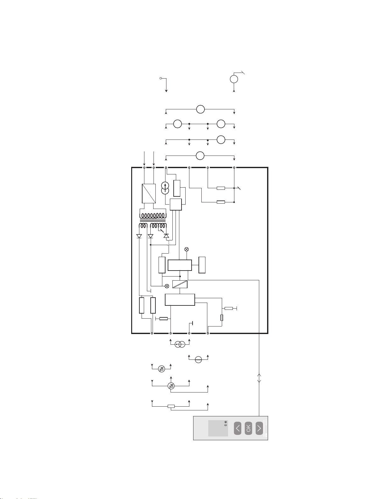
Block diagram
+ V supply
3.5...28.8 V
2-wire
-
mA
±
}
V
-
+
voltage
21.6...253 VAC or
19.2...300 VDC
31
33
HW
Vref.
Vloop
12
Watchdog
Red
mA
-
+
Buffer
D / A
CPU
CPU
10 V
10 V
mA
+
14
Green
1
EEPROM
2
A/D
1 V
1 V
-
13
V
-
+
V
-
+
Current & voltage Buered
11
DRST-DC
43
44
+
± 100 mA
-
+
2-wire
transmitter
+
+
meter
Potentio-
(Current)
42
-
-
-
41
-
+
± 300 V
(Voltage)
3-wire
transmitter
21
Page 22

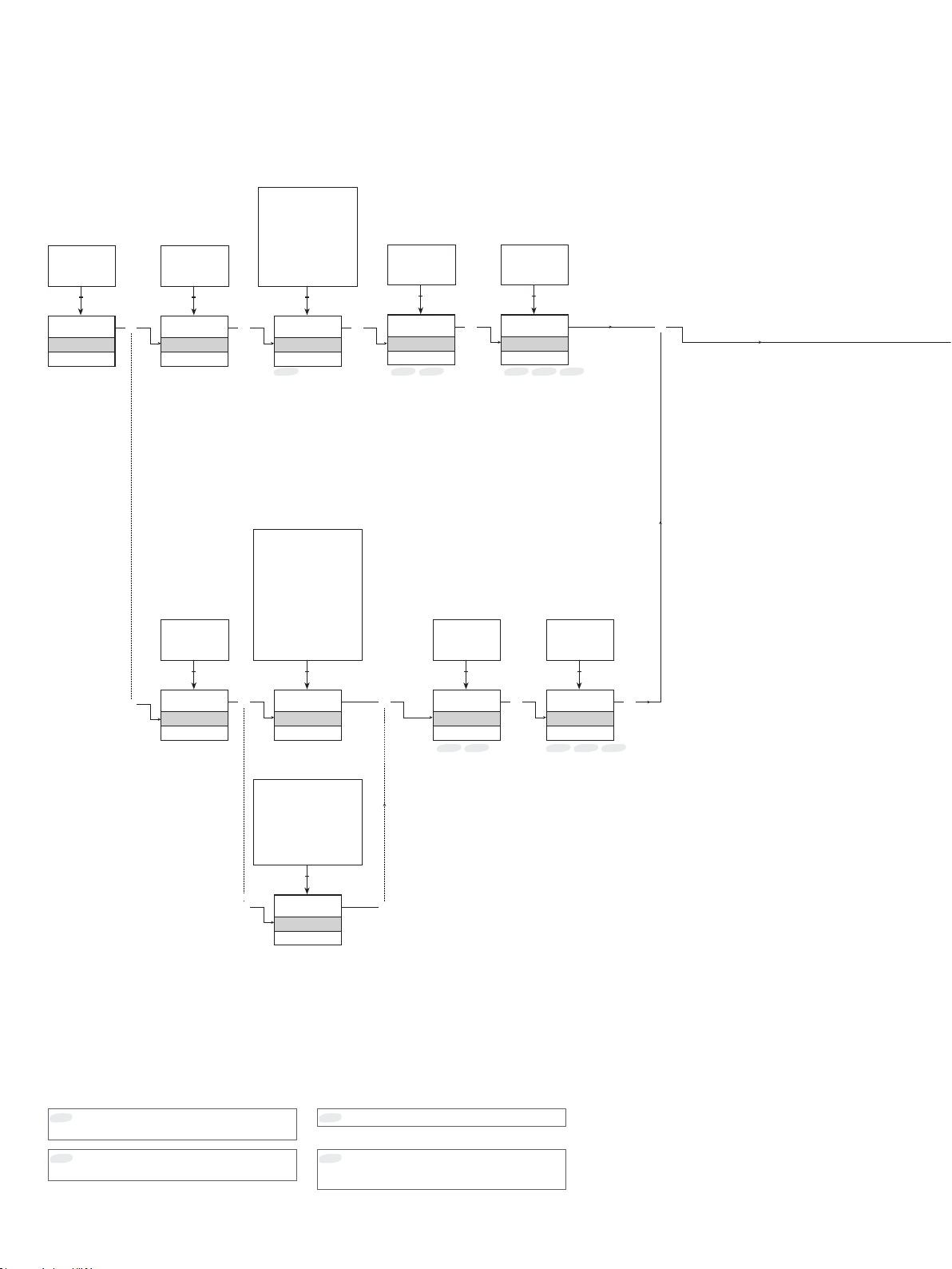
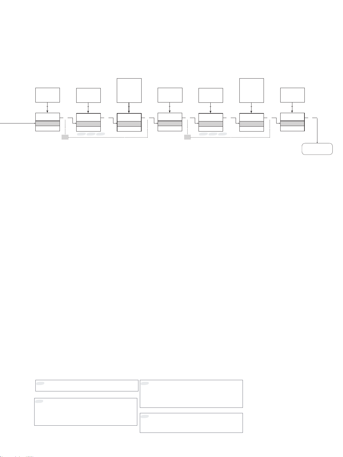
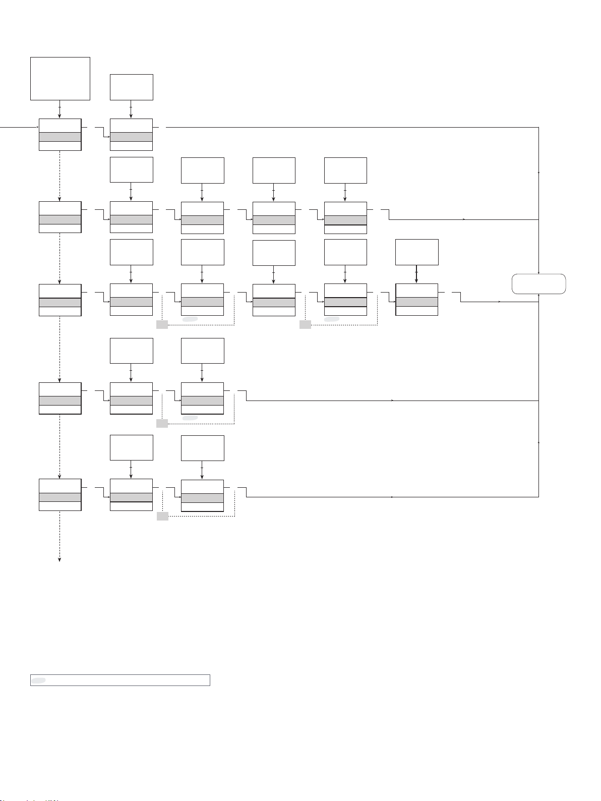
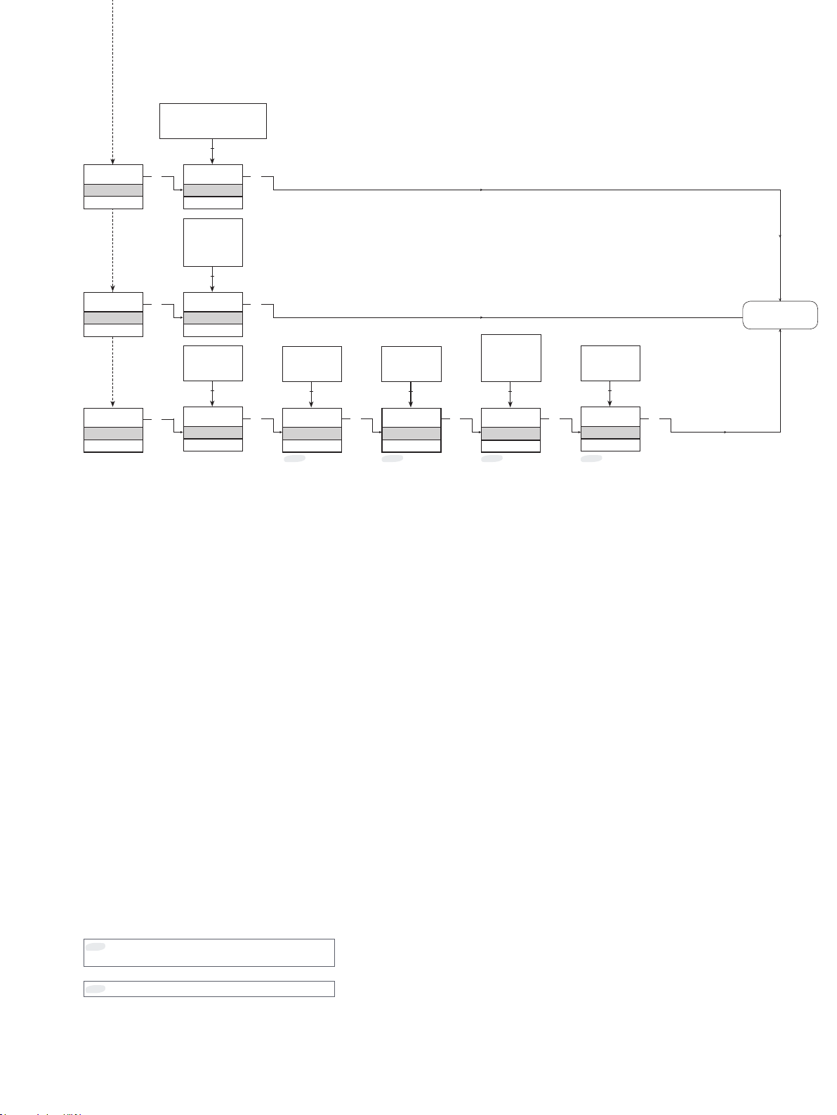
Configuration / operating the function keys
Documentation for routing diagram.
In general
When configuring the DRST-DC, you will be guided through all parameters and you can choose the settings which fit
the application. For each menu there is a scrolling help text which is automatically shown in line 3 on the display.
Configuration is carried out by use of the 3 function keys:
1 will increase the numerical value or choose the next parameter
2 will decrease the numerical value or choose the previous parameter
3 will save the chosen value and proceed to the next menu
When configuration is completed, the display will return to the default state 1.0. Pressing and holding
previous menu or return to the default state (1.0) without saving the changed values or parameters.
If no key is activated for 1 minute, the display will return to the default state (1.0) without saving the changed values or
parameters.
Further explanations
Password protection: Programming access can be blocked by assigning a password. The password is saved in the device in
order to ensure a high degree of protection against unauthorised modifications to the configuration. Default password 2008
allows access to all configuration menus.
Signal error indication via display front DRSL-DISPLAY & DRST-CM
Signal error is displayed as LO.ER (see table page 19). Input signals outside the selected range are displayed as IN.LO
indicating low input signal or IN.HI indicating high input signal (see table page 19). Error indication is displayed in line 1 as
text and at the same time the backlight flashes. A flashing bullet in line 4 is indicating correct functioning of DRSL-DISPLAY &
DRST-CM.
3 will return to the
Signal error indication without display front
Status of the unit can also be read from the red/green LED in the front of the device.
Green flashing LED 13 Hz indicates normal operation.
Green flashing LED 1 Hz indicates configurable input limit error.
Steady green LED indicates internal error.
Steady red LED indicates fatal error.
Advanced functions
The unit gives access to a number of advanced functions which can be reached by answering “Yes” to the point “ADV.SET”.
Memory (MEM): In the memory menu you can save the configuration of the device in the DRSL-DISPLAY & DRST-CM, and then
move the DRSL-DISPLAY & DRST-CM onto another device of the same type and download the configuration in the new device.
Display setup (DISP): Here you can adjust the brightness contrast and the backlight. Setup of TAG numbers with 6
alphanumerics. Selection of functional readout in line 3 of the display - choose between readout of analogue output or tag no.
Two-point process calibration (CAL): The device can be process-calibrated in 2 points to fit a given input signal . A low input
signal (not necessarily 0%) is applied and the actual value is entered via DRSL-DISPLAY & DRST-CM. Then a high signal (not
necessarily 100%) is applied and the actual value is entered via DRSL-DISPLAY & DRST-CM. If you accept to use the calibration,
the device will work according to this new adjustment. If you later reject this menu point or choose another type of input signal
the device will return to factory calibration.
Process simulation function (SIM): In the menu point “EN.SIM” it is possible to simulate an input signal by means of the arrow
keys and thus control the output signal up or down. You must exit the menu by pressing 3 (no time-out).
The simulation function exits automatically, if the DRSL-DISPLAY & DRST-CM is detached.
Password (PASS): Here you can choose a password between 0000 and 9999 in order to protect the unit against unauthorized
modifications to the configuration. The unit is delivered default without password.
22
Page 23

Language (LANG): In the menu ”LANG” you can choose between 7 different language versions of help texts that will appear
in the menu. You can choose between UK, DE, FR, IT, ES, SE and DK.
Output function (OFUN): Here the output characteristics can be set to either Direct (DIR) or Inverted (INV) function. Output
type and range are set in the normal programming menu. If the selected output range is starting at zero, V-curved output
function (VFUN) can also be selected. The output characteristics will then be 100-0-100% on the basis of a linear 0-100%
input signal.
Square root and low cut-off function (IFUN): Here it is possible to choose a square root relationship between input and
output and decide which section of the square root function that has to be used. The function includes a low cut-off point for
limiting "small" input signals. Cut-off type and cut-off value are also selected in this menu point.
Auto diagnostics
The device performs an advanced auto diagnosis of the internal circuits - check tables on page 19.
23
Page 24
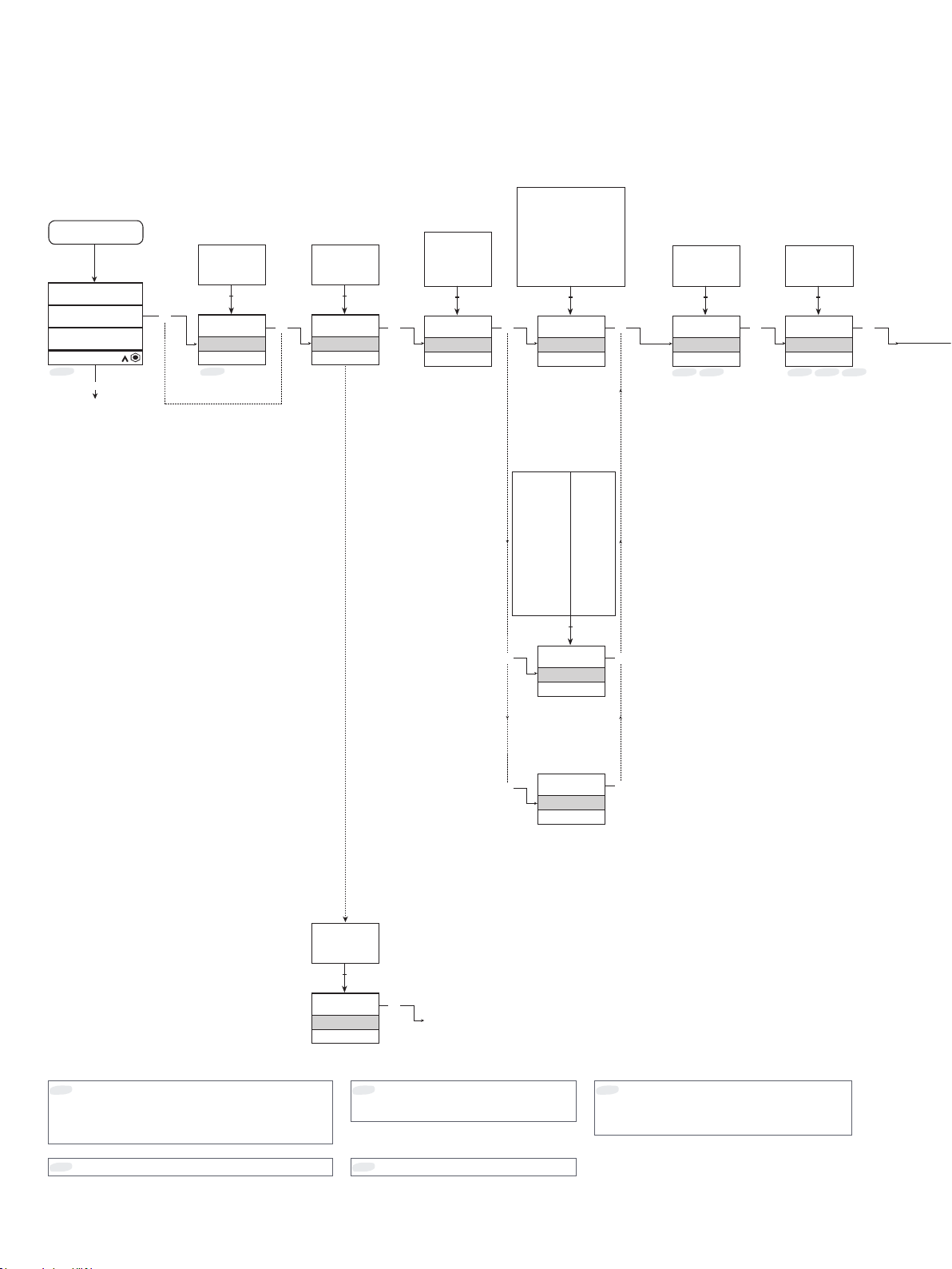
Routing diagram
If no key is activated for 1 minute, the display will return to the default state 1.0 without saving configuration changes.
1 Increase value / choose next parameter
2 Decrease value / choose previous parameter
3 Save the chosen value and proceed to the next menu
Hold 3 Back to previous menu / return to menu 1.0 without saving.
Power up
40.0
%
10.4 mA
*0
12
1 and 2 held:
Toggle line 3 function
A.Out / TAG.
(Setting is volatile - use
DISP setup menu to
change and store line 3
function).
-/+100
-/+50
-/+20
0
9999
Correct No
3
PASSW.
Txt 1
*1
Correct No
3
0
NO
YES
1 21 2
NO
ADV.SET
Txt 2
Yes
Yes
VOLT
CURR
1 2
CURR
IN TYPE
Txt 3
POTM
CURR
33
-/+10
-/+5
-/+1
-/+300
-/+100
-/+10
-/+5
-/+2.5
-/+1
-/+0.1
0-300
0-100
4-20
0-20
CUST
1 2
4-20
I.RANGE
Txt 4
2-10
0-10
0-5
0-2.5
0.2-1
0-0.1
CUST
1-5
0-5
0-1
1-5
0-1
99.9
-100.0
1 2
3
-100.0
IN.LO
Txt 48
*7 *11 *7 *9 *11
3
100.0
-99.9
1 2
100.0
IN.HI
Txt 49
3
1 2
VO LT
3
0-10
V.RANGE
Txt 5
3
Default state.
*0
Line 1 shows the scaled process value - OK or error.
Line 2 shows the selected engineering unit.
Line 3 shows analogue output or TAG no.
Line 4 shows status for communication and signal trending.
Only displayed if password is enabled.
*1
24
NO
YES
1 2
YES
ADV.SET
Txt 2
POTM
3
3
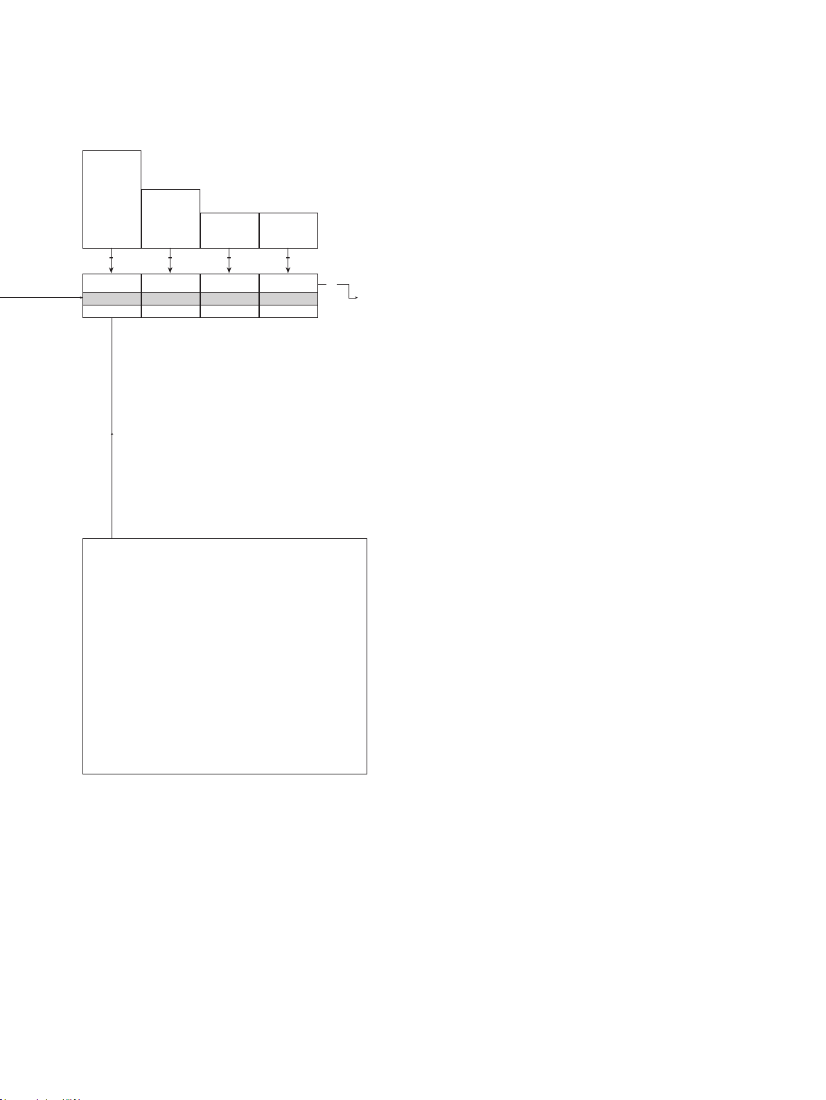
Continued on the page
Routing diagram ADV.SET
Only displayed if CUST input range or POTM
*7
is selected.
This menu will change range automatically.
Value will be forced to be greater than xx.LO.
*9
---
---
---
3
Limits are dependent on input type:
*11
CURR limits are: ±100.0
VOLT limits are: ±300
POTM limits are: 0 and 100.0
Page 25
[blank]
:
:
%
@F
@C
(69 units)
1 2
111.1
11.11
1.111
1111
1 2
9999
-1999
1 2
9999
-1999
1 2
UNIT
mA
Txt 6
@C
@F
%
A
bar
cm
ft
ft/h
ft/min
ft/s
g
gal/h
gal/min
GW
11.11
DEC.P
Txt 7
4.00
DISP.LO
Txt 8
Selectable UNITS:
hp
hPa
Hz
in
in/h
in/min
in/s
ips
K
kA
kg
kJ
kPa
kV
kW
kWh
l
l/h
l/min
l/s
m
m/h
m/min
m/s
m/s2
m3
m3/h
m3/min
20.00
DISP.HI
Txt 9
mA
mbar
mils
min
mm
mm/s
mol
Mpa
mV
MW
MWh
N
Ohm
Pa
3
Continued on the next page
pH
rpm
s
S
t
t/h
uA
um
uS
V
W
Wh
yd
[blank]
25
Page 26
CURR
VOLT
1 2
CURR
ANA.OUT
Txt 10
CURR
3
PASS
ACTI
1 2
ACTI
OUT.MOD
Txt 13
3
-/+20
-/+10
-/+5
S4-20
4-20
0-20
4-20
O.RANGE
Txt 11
*2
1 2
2-10
0-10
1-5
0-5
CUST
19.9
-20.0
1 2
3
-20.0
OUT.LO
Txt 50
*2 *8 *2 *8
20.0
-19.9
1 2
3
20.0
OUT.HI
Txt 51
*9
3
VSHU
VBUF
1 2
VO LT VBUF
VBUF
3
OUT.MOD
Txt 52
3
VSHU
3
-/+20
-/+10
-/+5
-/+2.5
-/+1
4-20
0-20
0-10
O.RANGE
Txt 12
-/+10
-/+5
-/+1
2-10
0-10
0-10
O.RANGE
Txt 12
1 2
1 2
2-10
0-10
1-5
0-5
0-2.5
0.2-1
0-1
CUST
1-5
0-5
0.2-1
0-1
CUST
19.9
-20.0
1 2
3
-20.0
OUT.LO
Txt 50
*8 *12 *8 *9 *12
3
20.0
-19.9
1 2
20.0
OUT.HI
Txt 51
3
3
If passive is selected, the values are limited to only
*2
positive span.
Only displayed if CUST output range is selected.
*8
This menu will change range automatically.
26
Value will be forced to be greater than xx.LO.
*9
Limits are dependent on output type:
*12
VBUF limits are: ±20.0
VSHU limits are: ±10.0
Page 27
YES
NO
1 2
4.00
-100.0
1 2
NONE
UP
ZERO
DOWN
1 2
YES
NO
1 2
100.00
20.00
1 2
NONE
UP
ZERO
DOWN
1 2
60.0
0.0
1 2
YES
ILIM.L
Txt 58
3 3 3 3
NO
3.80
Txt 59
*14
mA
*15 *17
UP
OUT.ERR
Txt 14
YES
ILIM.H
Txt 60
20.5
mA
Txt 61
*14NO*16 *17
3 3
UP
OUT.ERR
Txt 14
0.0
RESP.
Txt 15
3
To default state
1.0
Selectable in engineering units, i.e. Volt (V), Current (mA) or
*14
Potentiometer (%).
Limits are dependent on input type and the selected input
*15
range:
High Limit: 'Minimum input'
Low limit, CURR: -100.0 mA
Low limit, VOLT: -300 V
Low limit, POT M: 0 %
Limits are dependent on input type and the selected input
*16
range:
Low Limit: Maximum input'
High limit, CURR: 100.0 mA
High limit, VOLT: 300 V
High limit, POTM: 100.0 %
If the selected input range is changed to 4...20 mA the
*17
configurable limits are initially set to the following:
Range limit, L ow 3.6 mA
Range limit, High 21 mA
27
Page 28
MEM, DISP,
CAL, SIM,
PASS, LANG,
OFUN, IFUN
1 2
Routing diagram, advanced settings (ADV.SET)
SAVE
LOAD
1 2
MEM
SETUP
Txt 16/1
DISP
SETUP
Txt 16/2
CAL
SETUP
Txt 16/3
SIM
SETUP
Txt 16/4
SAVE
MEMORY
Txt 17
1 2
3
CONTRA
Txt 18
YES
NO
1 2
NO
CAL.LO
Txt 22
YES
NO
1 2
3
NO
ENA.SIM
Txt 27
33
9
0
9
0
1 2
9
LIGHT
Txt 19
3 3 333
20.00
4.00
1 2
4.00
Txt 23
*5
NO NO
3 3 333 3
mA
20.00
4.00
1 2
3
NO
12.0
Txt 28
*5
3
mA
9
A
1 2
TAG
A.OUT
1 2
A.OUT
TAGNO_
Txt 20
YES
NO
1 2
NO
CAL.HI
Txt 24
In
the sub-menu simulation (SIM) you must press 3 or remove the
DRSL-DISPLAY & DRST-CM to return to the default state 1.0.
LINE 3
Txt 21
20.00
4.00
1 2
16.00
Txt 25
*5
mA
YES
NO
1 2
NO
USE.CAL
Txt 26
To default state
1.0
YES
NO
1 2
PASS
SETUP
Txt 16/5
Continued on
the next page
Selectable range as defined by DEC.P, DISP.LO and DISP.HI.
*5
NO
EN.PASS
Txt 29
NO
9999
0
1 2
0
NEW.PAS
Txt 30
333
28
Page 29
DE, DK, ES, FR,
IT, SE, UK
1 2
LANG
SETUP
Txt 16/6
OFUN
SETUP
Txt 16/7
IFUN
SETUP
Txt 16/8
UK
LANGUA.
Txt 31
33
VFUN
INV
DIR
1 2
DIR
O.FUNC
Txt 32
33
To default state
1.0
ZERO
LIN
SQRT
1 2
3
LIN
I.FUNC
Txt 55
0.000
1.000
1 2
0.000
SQRT.LO
Txt 53
*10
3 3 33
0.000
1.000
1 2
1.000
SQRT.HI
Txt 54
*10 *10 *13
LIN
NONE
1 2
ZERO
CUT.TYP
Txt 56
0.0
50.0
1 2
5.0
LO.CUT
Txt 57
3
Only displayed if SQRT is selected!
*10
SQRT.LO and SQRT.HI must not be equal.
Only shown if CUT.TYP is NOT set to NONE.
*13
29
Page 30

Help text overview
[1]
Set correct password
[2]
Enter advanced setup menu?
[3]
Select current input
Select voltage input
Select potmeter input
[4]
Select -100...100 mA input range
Select -50...50 mA input range
Select -20...20 mA input range
Select -10...10 mA input range
Select -5...5 mA input range
Select -1...1 mA input range
Select 4...20 mA input range
Select 0...20 mA input range
Select 1...5 mA input range
Select 0...5 mA input range
Select 0...1 mA input range
Select custom current input range
[5]
Select -300...300 V input range
Select -100...100 V input range
Select -10...10 V input range
Select -5...5 V input range
Select -2.5...2.5 V input range
Select -1...1 V input range
Select -100...100 mV input range
Select 0...300 V input range
Select 0...100 V input range
Select 2...10 V input range
Select 0...10 V input range
Select 1...5 V input range
Select 0...5 V input range
Select 0...2.5 V input range
Select 0.2...1 V input range
Select 0...1 V input range
Select 0...100 mV input range
Select custom voltage input range
[6]
Select display unit
[7]
Select decimal point position
[8]
Set display range low
[9]
Set display range high
[10]
Select current as analog output type
Select voltage as analog output type
[11]
Select -20...20 mA output range
Select -10...10 mA output range
Select -5...5 mA output range
Select 4...20 mA output range with safety readback
Select 4...20 mA output range
Select 0...20 mA output range
Select 2...10 mA output range
Select 0...10 mA output range
Select 1...5 mA output range
Select 0...5 mA output range
Select custom current output range
[12]
Select -20...20 V output range
Select -10...10 V output range
Select -5...5 V output range
Select -2.5...2.5 V output range
Select -1...1 V output range
Select 4...20 V output range
Select 0...20 V output range
Select 2...10 V output range
Select 0...10 V output range
Select 1...5 V output range
Select 0...5 V output range
Select 0...2.5 V output range
Select 0.2...1 V output range
Select 0...1 V output range
Select custom voltage output range
[13]
Select active output mode
Select passive output mode
[14]
Select downscale at error
Select zero output at error
Select upscale at error
Select no error action - output undefined at error
[15]
Set analog output response time in seconds
[16]
Select analog output function
Enter Language setup
Enter Password setup
Enter Simulation mode
Perform Process calibration
Enter Display setup
Perform Memory operations
Select analog input function
[17]
Load saved configuration into module
Save configuration in display front
[18]
Adjust LCD contrast
[19]
Adjust LCD backlight
[20]
Write a 6-character device TAG
[21]
Analog output value is shown in display line 3
Device TAG is shown in display line 3
[22]
Calibrate Input low to process value?
[23]
Set value for low calibration point
[24]
Calibrate Input high to process value?
[25]
Set value for high calibration point
[26]
Use process calibration values?
[27]
Enable simulation mode?
[28]
Set the input simulation value
[29]
Enable password protection?
[30]
Set new password
[31]
Select language
[32]
Select direct output mode
Select inverted output mode
Select V-function output mode
[33]
Display underrange
[34]
Display overrange
[35]
Input underrange
[36]
Input overrange
[37]
Analog output supply error
[38]
Analog output error - check output connections and
reset power
[39]
Configuration error - default configuration is loaded
[40]
RAM memory error
[41]
Invalid configuration
30
Page 31

[42]
[43]
[44]
[45]
[46]
[47]
[48]
[49]
[50]
[51]
[52]
[53]
[54]
[55]
[56]
[57]
[58]
[59]
[60]
[61]
A/D converter error
No communication
Input range limit error - Input outside
configurable input range limit
Invalid configuration type or version
External flash error
Internal flash error
Set input range low
Set input range high
Set output range low
Set output range high
Select buffered voltage output
Select shunted voltage output
Select low value of square root
Select high value of square root
Select linear input function
Select square root input function
Set low cut-off type to zero
Set low cut-off type to linear
Disable low cut-off
Select low cut-off point in % of input range
Enable configurable input error limit, low
Set configurable input limit, low
Enable configurable input error limit, high
Set configurable input limit, high
31
Page 32

WARRANTY/DISCLAIMER
OMEGA ENGINEERING, INC. warrants this unit to be free of defects in materials and workmanship for a
period of 13 months from date of purchase. OMEGA’s WARRANTY adds an additional one (1) month
grace period to the normal one (1) year product warranty to cover handling and shipping time. This
ensures that OMEGA’s customers receive maximum coverage on each product.
If the unit malfunctions, it must be returned to the factory for evaluation. OMEGA’s Customer Service
Department will issue an Authorized Return (AR) number immediately upon phone or written request.
Upon examination by OMEGA, if the unit is found to be defective, it will be repaired or replaced at no
charge. OMEGA’s WARRANTY does not apply to defects resulting from any action of the purchaser,
including but not limited to mishandling, improper interfacing, operation outside of design limits,
improper repair, or unauthorized modification. This WARRANTY is VOID if the unit shows evidence of
having been tampered with or shows evidence of having been damaged as a result of excessive corrosion;
or current, heat, moisture or vibration; improper specification; misapplication; misuse or other operating
conditions outside of OMEGA’s control. Components in which wear is not warranted, include but are not
limited to contact points, fuses, and triacs.
OMEGA is pleased to offer suggestions on the use of its various products. However,
OMEGA neither assumes responsibility for any omissions or errors nor assumes liability for
any damages that result from the use of its products in accordance with information provided
by OMEGA, either verbal or written. OMEGA warrants only that the parts manufactured by the
company will be as specified and free of defects. OMEGA MAKES NO OTHER WARRANTIES OR
REPRESENTATIONS OF ANY KIND WHATSOEVER, EXPRESSED OR IMPLIED, EXCEPT THAT OF
TITLE, AND ALL IMPLIED WARRANTIES INCLUDING ANY WARRANTY OF MERCHANTABILITY
AND FITNESS FOR A PARTICULAR PURPOSE ARE HEREBY DISCLAIMED. LIMITATION OF
LIABILITY: The remedies of purchaser set forth herein are exclusive, and the total liability of
OMEGA with respect to this order, whether based on contract, warranty, negligence,
indemnification, strict liability or otherwise, shall not exceed the purchase price of the
component upon which liability is based. In no event shall OMEGA be liable for
consequential, incidental or special damages.
CONDITIONS: Equipment sold by OMEGA is not intended to be used, nor shall it be used: (1) as a “Basic
Component” under 10 CFR 21 (NRC), used in or with any nuclear installation or activity; or (2) in medical
applications or used on humans. Should any Product(s) be used in or with any nuclear installation or
activity, medical application, used on humans, or misused in any way, OMEGA assumes no responsibility
as set forth in our basic WARRANTY/DISCLAIMER language, and, additionally, purchaser will indemnify
OMEGA and hold OMEGA harmless from any liability or damage whatsoever arising out of the use of the
Product(s) in such a manner.
RETURN REQUESTS/INQUIRIES
Direct all warranty and repair requests/inquiries to the OMEGA Customer Service Department.
BEFORE RETURNING ANY PRODUCT(S) TO OMEGA, PURCHASER MUST OBTAIN AN AUTHORIZED
RETURN (AR) NUMBER FROM OMEGA’S CUSTOMER SERVICE DEPARTMENT (IN ORDER TO AVOID
PROCESSING DELAYS). The assigned AR number should then be marked on the outside of the return
package and on any correspondence.
The purchaser is responsible for shipping charges, freight, insurance and proper packaging to prevent
breakage in transit.
FOR WARRANTY RETURNS, please have the
following information available BEFORE contacting
OMEGA:
1. Purchase Order number under which the product
was PURCHASED,
2. Model and serial number of the product under
warranty, and
3. Repair instructions and/or specific problems
relative to the product.
OMEGA’s policy is to make running changes, not model changes, whenever an improvement is possible. This affords
our customers the latest in technology and engineering.
OMEGA is a trademark of OMEGA ENGINEERING, INC.
© Copyright 2018 OMEGA ENGINEERING, INC. All rights reserved. This document may not be copied, photocopied,
reproduced, translated, or reduced to any electronic medium or machine-readable form, in whole or in part, without the
prior written consent of OMEGA ENGINEERING, INC.
FOR NON-WARRANTY REPAIRS,
OMEGA for current repair charges. Have
the following information available BEFORE
contacting OMEGA:
1. Purchase Order number to cover the COST
of the repair,
2. Model and serial number of the product, and
3. Repair instructions and/or specific problems
relative to the product.
consult
Page 33

Where Do I Find Everything I Need for
Process Measurement and Control?
OMEGA…Of Course!
Shop online at omega.com
TEMPERATURE
MU
Thermocouple, RTD & Thermistor Probes, Connectors, Panels & Assemblies
MU
Wire: Thermocouple, RTD & Thermistor
MU
Calibrators & Ice Point References
MU
Recorders, Controllers & Process Monitors
MU
Infrared Pyrometers
PRESSURE, STRAIN AND FORCE
MU
Transducers & Strain Gages
MU
Load Cells & Pressure Gages
MU
Displacement Transducers
MU
Instrumentation & Accessories
FLOW/LEVEL
MU
Rotameters, Gas Mass Flowmeters & Flow Computers
MU
Air Velocity Indicators
MU
Turbine/Paddlewheel Systems
MU
Totalizers & Batch Controllers
pH/CONDUCTIVITY
MU
pH Electrodes, Testers & Accessories
MU
Benchtop/Laboratory Meters
MU
Controllers, Calibrators, Simulators & Pumps
MU
Industrial pH & Conductivity Equipment
DATA ACQUISITION
MU Communications-Based Acquisition Systems
MU Data Logging Systems
MU Wireless Sensors, Transmitters, & Receivers
MU Signal Conditioners
MU Data Acquisition Software
HEATERS
MU
Heating Cable
MU
Cartridge & Strip Heaters
MU
Immersion & Band Heaters
MU
Flexible Heaters
MU
Laboratory Heaters
ENVIRONMENTAL
MONITORING AND CONTROL
MU
Metering & Control Instrumentation
MU
Refractometers
MU
Pumps & Tubing
MU
Air, Soil & Water Monitors
MU
Industrial Water & Wastewater Treatment
MU
pH, Conductivity & Dissolved Oxygen Instruments
M5723
/1118
 Loading...