

Page 1
TM
User’s Guide
Shop online at
omega.com
e-mail: [email protected]
For latest product manuals:
www.omegamanual.info
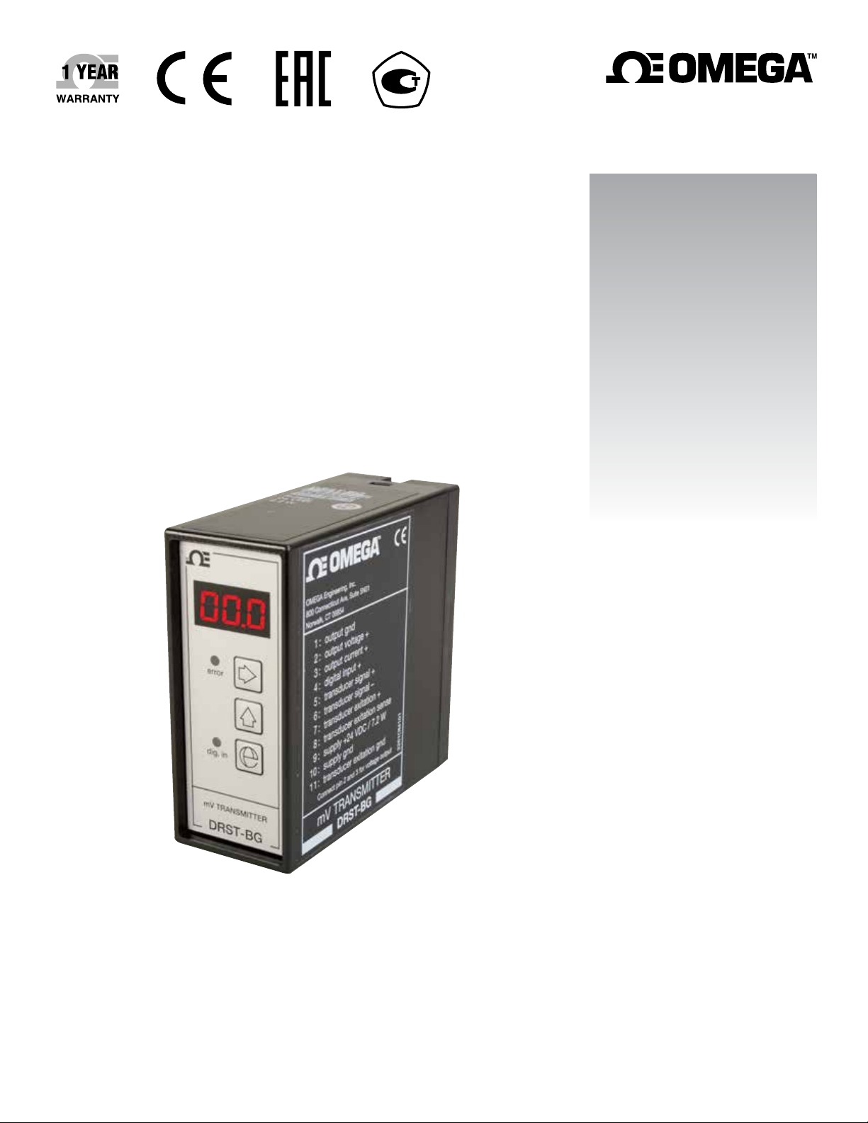
DRST-BG
MV Transmitter
Page 2

omega.com [email protected]
Servicing North America:
U.S.A. Omega Engineering, Inc.
Headquarters: Toll-Free: 1-800-826-6342 (USA & Canada only)
Customer Service: 1-800-622-2378 (USA & Canada only)
Engineering Service: 1-800-872-9436 (USA & Canada only)
Tel: (203) 359-1660 Fax: (203) 359-7700
e-mail: [email protected]
For Other Locations Visit omega.com/worldwide
The information contained in this document is believed to be correct, but OMEGA accepts no liability for any errors it contains, and reserves
the right to alter specifications without notice.
Page 3

Table of
Contents
DRST-BG MV Transmitter
Table of Contents
Section ........................................................................ Page
Section 1 Introduction .................................................................................... 4
1.2 Supply ......................................................................................... 4
1.3 Input Range ............................................................................... 4
1.4 Output Range ............................................................................ 4
1.5 Application ................................................................................. 4
1.6 Technical Characteristics ......................................................... 5
1.7 Inputs .......................................................................................... 5
1.8 Digital input ............................................................................... 5
1.9 Taring .......................................................................................... 5
1.10 Standard current/voltage output ......................................... 5
Section 2 Specifications .................................................................................. 6
2.1 Front error LED ......................................................................... 6
2.2 Transducer supply .................................................................... 6
2.3 Sense ........................................................................................... 6
2.4 Common Specifications ............................................................ 6
2.5 Auxilary voltage ........................................................................ 6
2.6 mV input .................................................................................... 7
2.7 Digital input ............................................................................... 7
2.8 Electrical specifications - Output ............................................ 7
2.9 Voltage output through internal shunt ................................. 8
2.10 Observed authority requirements ........................................ 8
2.11 Order ......................................................................................... 8
2.12 Hardware programming ....................................................... 8
Section 3 Diagrams .......................................................................................... 9
3.1 Block Diagram ........................................................................... 9
3.2 Routing Diagram .................................................................... 10
Section 4 Programming .......................................................................... 11-12
Section 5 Description of functions ............................................................. 13
5.1 CAL - Setting of Calibration values ..................................... 13
5.2 CLO - Setting of low Calibration values .............................. 13
5.3 CHI - Setting of Calibration values ...................................... 13
5.4 OUt - Setting of Analogue output ......................................... 13
5.5 tAR - Selection of taring type ................................................ 14
5.6 dIN - Selection of digital input type ..................................... 14
5.7 SUP - Setting of supply voltage for transducer .................. 14
5.8 PAS - Setting of Password ..................................................... 14
5.9 Frq - Selection of common mode .......................................... 14
Section 6 Display ..................................................................................... 15-16
3
Page 4

Section 1 - Introduction
• Load cell amplifier.
• mV to current/voltage conversion.
• Front-programmable/LED display.
• Relative valibration of input span.
• NPN/PNP input for external taring
• Supply for standard transducers
1.2 Supply
• Supply voltage: 24 VDC
• Transducer supply: 5.13 VDC
1.3 Input Range
• Measurement range: -40...100 mV
• Taring input: PNP/NPN/Front Key
1.4 Output Range
Introduction
1
• Current output: 0...20 mA
• Voltage output: 0...10 V
1.5 Application
• Tank filing and draining
• Weighing with a taring function
• Measurement of cable tensile force
• Level control
• Signal conversion/amplification
The DRST-BG converts bipolar mV signals from transducers supplied directly by the
module to standard current / voltage signals. The DRST-BG is suitable for load cell
applications. By way of the relative calibration function the scale can be tared, i.e. 0
and 100% calibrated without the need of the equivalent load. By way of the taring
function the measured range is set to either 0% when filling or 100% when draining.
4
Page 5

1
Introduction
Section 1.6 - Technical characteristics
In General, The DRST-BG is microprocessor-controlled and basic-calibrated meaning
that input and output can be programmed acc. to the requested signal range without
any readjust ment. This guarantees high accuracy and flexibility.
The user interface consists of a 3-digit display and 3 front function keys which are
used for taring or change of input / output signal range.
Section 1.7 - Inputs, Analog input
The analog input can be programmed for voltage in the range -40...100 mVDC with a
min. span of 10 mV and max. offset of 70% of max. mV value.
A percentage overrange of the selected measurement range can be defined, thereby making the unit react to an mV input outside the selected 0 and 100% range. The
display will show the input percentage.
The output must be scaled in such a way that the selected overrange is within the
allowed output signal range.
Section 1.8 - Digital input
The digital signal can be selected as either NPN (short circuit to gnd.), or PNP (+24
VDC).
Section 1.9 - Taring
Taring can either be by way of the digital input or from the front.
At 0% taring, the analog input will show 0% after taring. At 100% taring, the analog
input will show 100% after taring, corresponding to tara + net weight = gross weight.
The analog input span is not changed but is kept relative to the new offset value. The
taring function can be disabled at the front.
Section 1.10 - Standard current/ voltage output
The analog output can be programmed to current in the range 0...20 mA or voltage in
the range 0...10 VDC with a min. span of 5 mA or 250 mVDC with max. offset of 50%
of the selected max. value.
By short-circuiting pins 2 and 3, the voltage signal is available between pins 2 and 1.
For voltage signals in the range 0...1 VDC, a 50 Ω shunt (DP 2-1) is applied; in the
range 0...10 VDC, a 500 Ω shunt (DP 2-2) is applied.
When both voltage and current signals are used simultaneously, the mA loop must go
to ground through the internal shunt.
5
Page 6
Section 2.1 - Front error LED
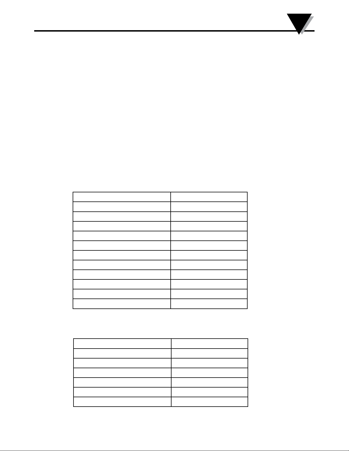
At an incorrect output, the red LED will flash, e.g. at overrange saturation.
Section 2.2 - Transducer supply
Front-programmable to 5...13 VDC. The supply is short circuit-protected and has a
max. load of 230 mA (e.g. 6 parallel 350 Ω load cells).
Section 2.3 - Sense
When the transducer supply is applied, the sense input can be used for compensation
for cable resistance to the transducer.
Specifications range: -20°C to +60°C
Section 2.4 - Common Specifications
Specifications
2
Supply voltage 19.2...28.8 VDC
Internal consumption 2.2 W
Max. consumption 7.2 W
Signal / noise ratio Min. 60 dB
Signal dynamics, input 17 bit
Signal dynamics, output 16 bit
Updating time 20 ms
Response time, programmable 0.06...999 s
Calibration temperature 20...28°C
Temperature coeffici ent < ±0.01% of span / °C
Linearity error ≤ ±0.1% of span
Effect of supply voltage change < ±0.002% of span/ %V
Section 2.5 - Auxilary voltage
Transducer supply 5...13 VDC
Load (max.) 230 mA
EMC immunity influence < ±0.5% of span
Relative air humidity < 95% RH (non-cond.)
Dimensions (HxWxD) 80.5 x 35.5 x 84.5 mm
Protection degree IP50
Weight 130 g
6
Page 7
2
Specifications
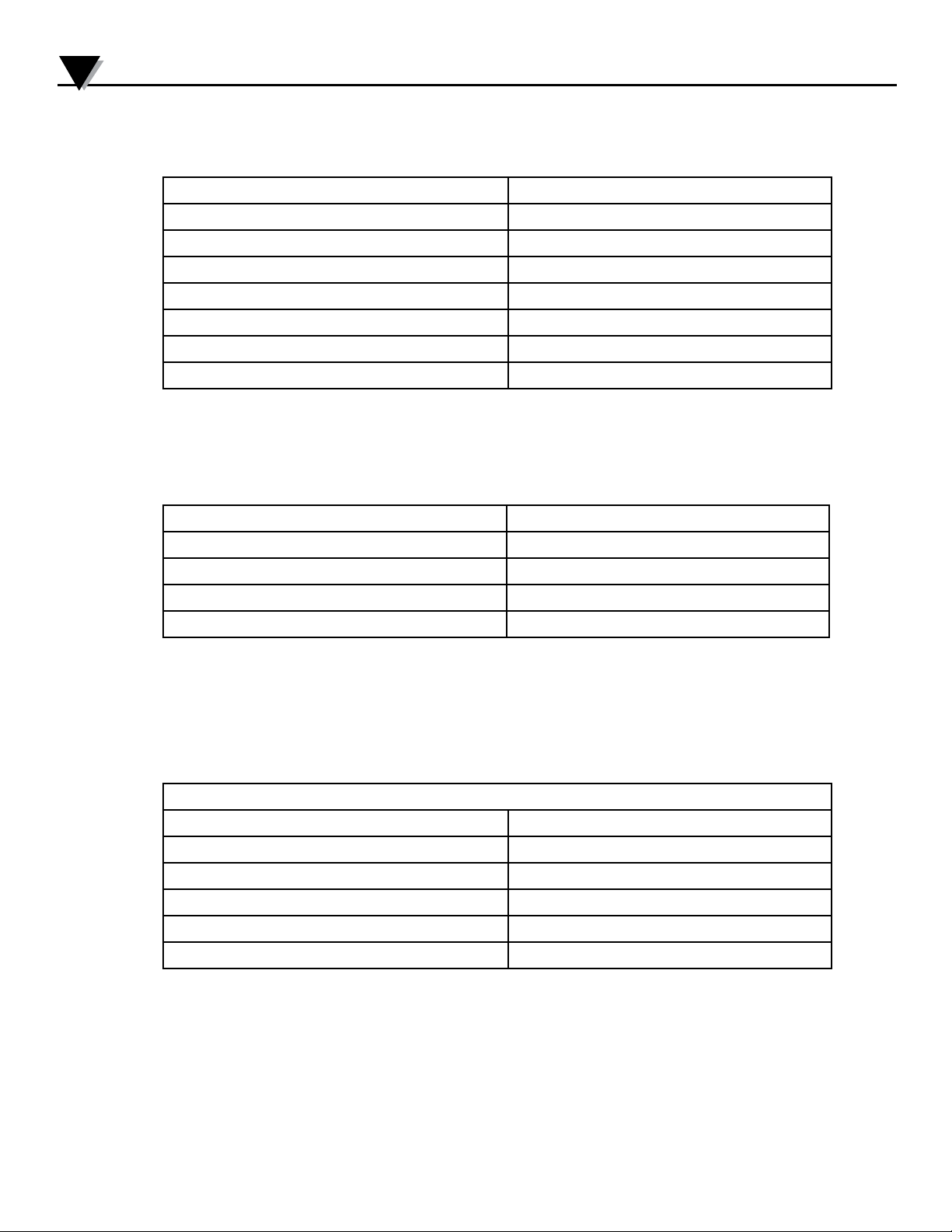
Section 2.6 - mV input
Measurement range -40...100 mV
Min. measurement range (span) 10 mV
Max. offset 70% of selected max. value
Input in relation to supply gnd > -5 V and < +10 V
Max. cable resistance per wire 15 Ω
Suppression of transducer cable resistance > 300
Input resistance > 10 MΩ
Overrange 0...999% of selected measurement range
Section 2.7 - Digital input
NPN Pull up 24 VDC / 6.9 mA
PNP Pull down 0 VDC / 6.9 mA
Trig level low < 6 VDC
Trig level high > 10.5 VDC
Pulse width > 30 ms
Section 2.8 - Electrical specifications - Output:
Current output:
Signal range 0...20 mA
Min. signal range (span) 5 mA
Max. offset 50% of selected max. value
Load (max.) 20 mA / 600 Ω / 12 VDC
Load stability < ±0.01% of span/100 Ω
Current limit < 23 mA
7
Page 8
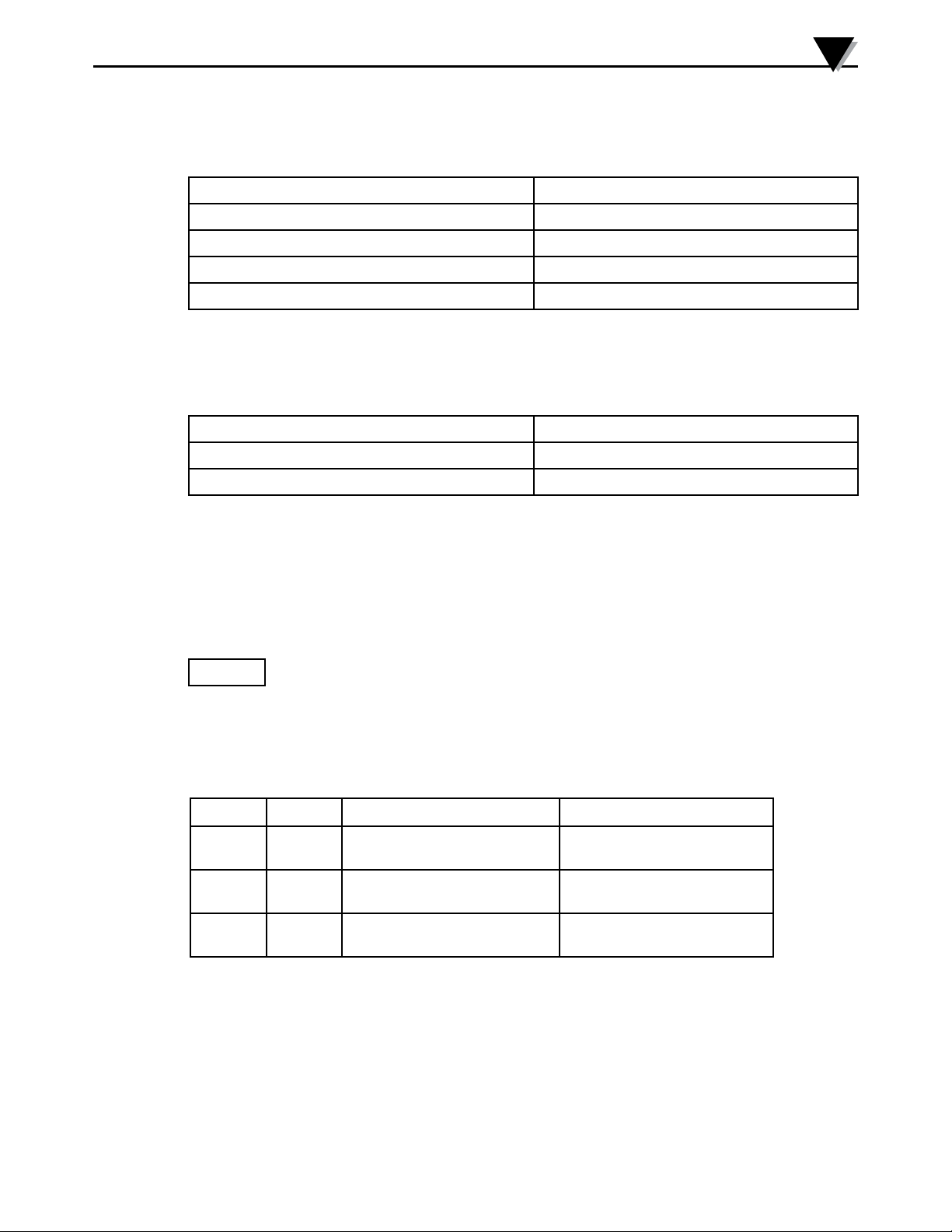
Section 2.9 - Voltage output through internal shunt
Signal range 0...10 VDC
Min. signal range (span) 250 mVDC
Max. offset 50% of selected max. value
Load (min.) 500 kΩ
Voltage limit < 11.5 VDC
Section 2.10 - Observed authority requirements
Observed authority requirements: Standard:
EMC 2004/108/EC EN 61326-1
EAC TR-CU 020/2011 EN 61326-1
Specifications
2
Of span = Of the presently selected range
Section 2.11 - Order
Type
Section 2.12 - Hardware programming
JP1 JP2 Output range Menu 4.3
OFF OFF 0...10 mA
0...20 mA
ON OFF 0...500 mV
0...1000 mV
OFF ON 0...5 V
0...10 V
001
002
003
004
005
006
8
Page 9
3
Diagrams
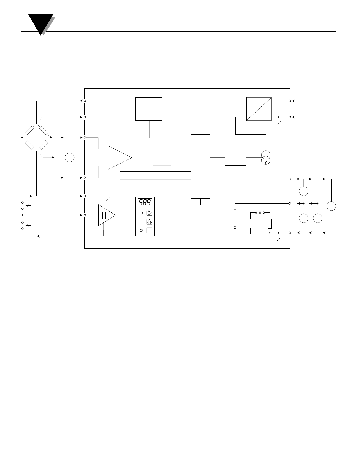
Section 3.1 - Block Diagram
V Excitation +
Sense
NC
V Excitation
NPN
Digital
PNP
+ 24
VDC
Sens
Input
+
mV
-
Input
gnd.
Input
Supply + 24VDC
7
eg
8
e
+
5
PGA
Vr
A / D
CPU
D /
DC
DC
24 VDC
A
6
-
11
Spec.
V Out
R 68
JP1 JP2
50 500
4
EEPROM
e
9
10
0...20
mA
3
2
1
Supply gnd.
I
+ V
V
Out
I+
Out
A
V+
V V
Gnd.
I
Out
A
2261
9
Page 10
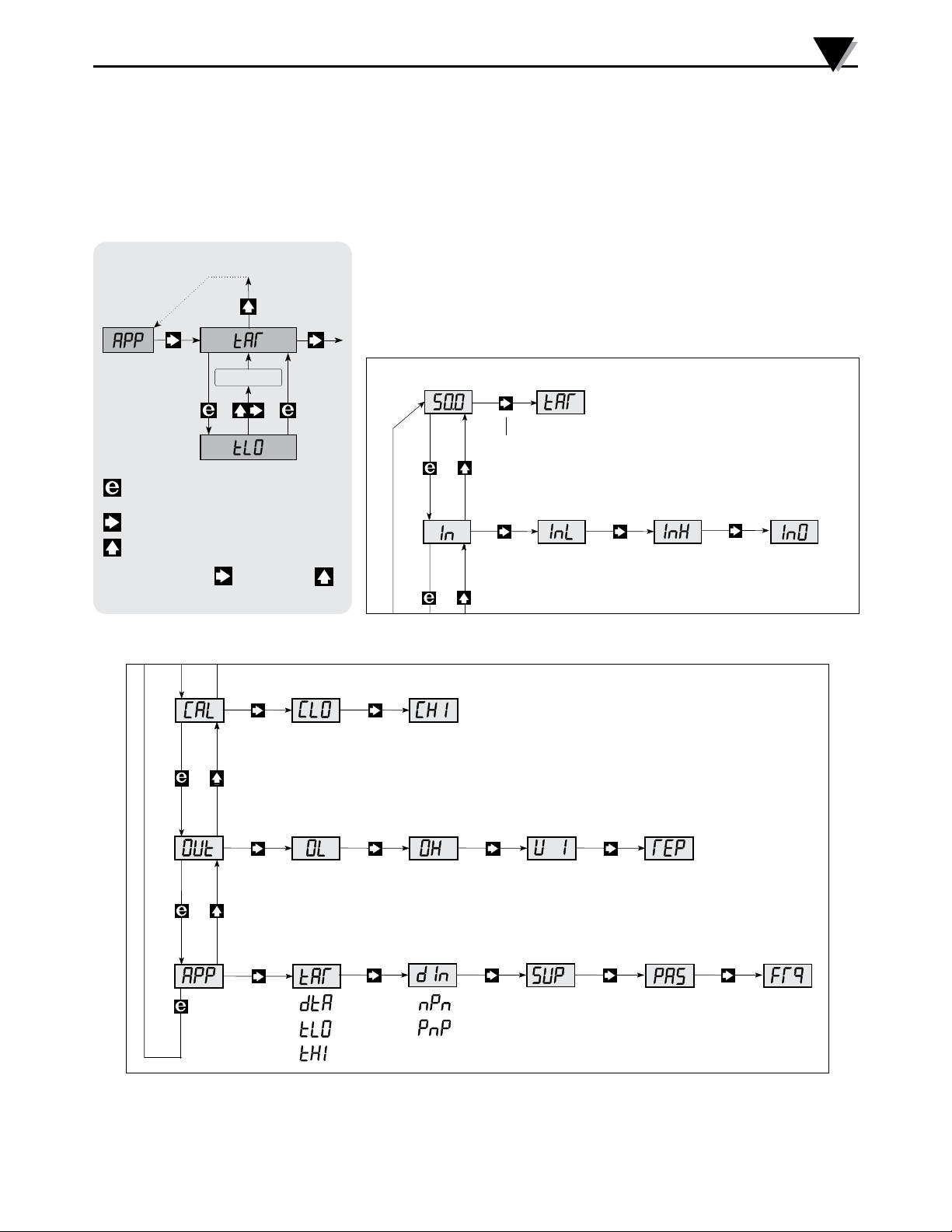
Section 3.2 - Routing Diagram
Info buttons are pressed for a period of 2 minutes, display returns to stage 0.0
Diagrams
3
Programming
5.0
Go to entry menu / Leave
menu
Next
Change
Press and hold
to store change s
5.1
Memory
withou t changes
digit or point
paramete r
of
, then press
3 . 0
Low cal. %
3 . 1
0 . 0
Taring
If the key is pressed for a period > 2 sec.
3 . 2
1 . 0
High cal. % Calibration
Input Overrang e
Input 0%
1 . 1
-40...10 0 mV -40...10 0 mV
Input 100%
1 . 2
1 . 3
0...999 % of span
4 . 0
5 . 0
0...100%
Analog
output Output 0%
4 . 1
0...20.0 mA
0...10.0 VDC
Select
application
Taring
5 . 1
0...100%
Output 100%
4 . 2
0...20.0 mA
0...10.0 VDC
Digital input
type
5 . 2
Current or
Voltage
4 . 3 4 . 4
001 = 0...10 mA
002 = 0...20 mA
003 = 0...500 mV
004 = 0...1000 mV
005 = 0...5 V
006 = 0...10 V
Transducer supply
5 . 3
5.0...13 VDC
10
Response
time
0.06...999 s
Program
access
5 . 4
0 9 9 9
Password code
040 = enable change in all stages
- - - = disable change
Frequency
suppression
5 . 5
50 Hz
60 Hz
Page 11
4
Programming
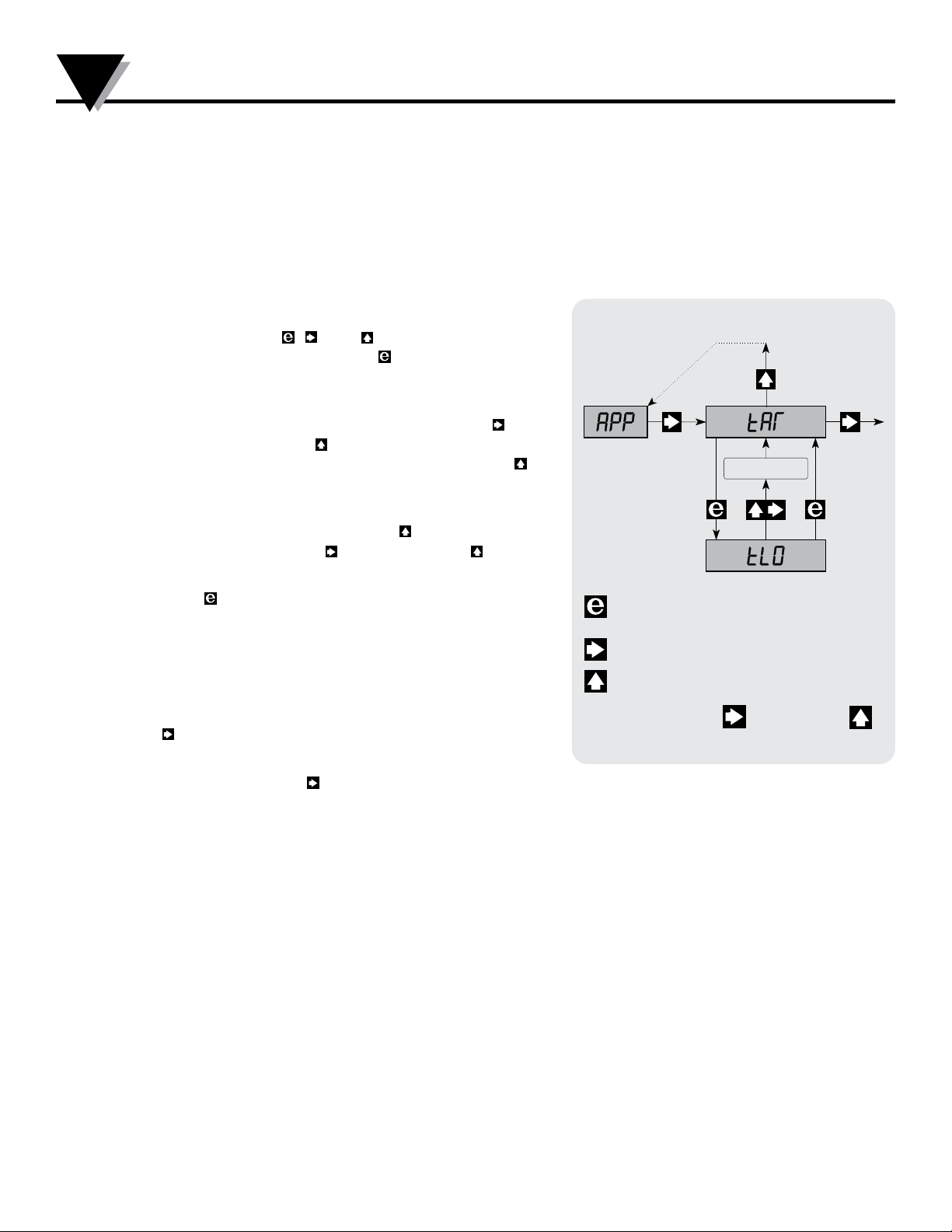
Section 4.1 - Programming/Operating the function keys
The programming is menu-controlled. The main menus are numbered in level 0 (X.0), and the
submenus are numbered in level 1 (X.1 - X.5). Each submenu has an accompa nying entry menu.
The menus are structured in such a way that the menus most frequently used are closer to the
default menu 0.0. Please note that programming is only possible when submenu 5.4 PAS has the
value 040.
Main, sub, and entry menus are selected by the
3 function keys , , and as outlined in the
routing diagram. Activating in the submenus
will display the set value in the entry menu.
In entry menus, the digit that can be changed will
flash. Active digit position is shifted by the key
and changed by the key. When the decimal
point flashes, its position can be shifted by the
key.
In entry menus with fixed parameters, you switch
between the parameters by the key. Store
by first activating the key and then the key
simultaneously.
Press to return to the previous menu without
changing the parameter.
0.0 DEFAULT - The input value is displayed in
% of the input span. At power ON, or if no keys
have been activated for a period of 2 minutes, the
display returns to default.
tAR - Taring
When submenu 5.1 has been selected for {tLO or
tHI}, activating the key for more than 2 s will
tare the input value to the value it had
Programming
5.0
Go to entry menu / Leave
menu
Next
Change
Press and hold
to store changes
5.1
Memory
withou t change s
digit or point
paramete r
of
, then press
when activated. The input span is not affected but
is kept relative to the new offset value.
11
Page 12
Programming
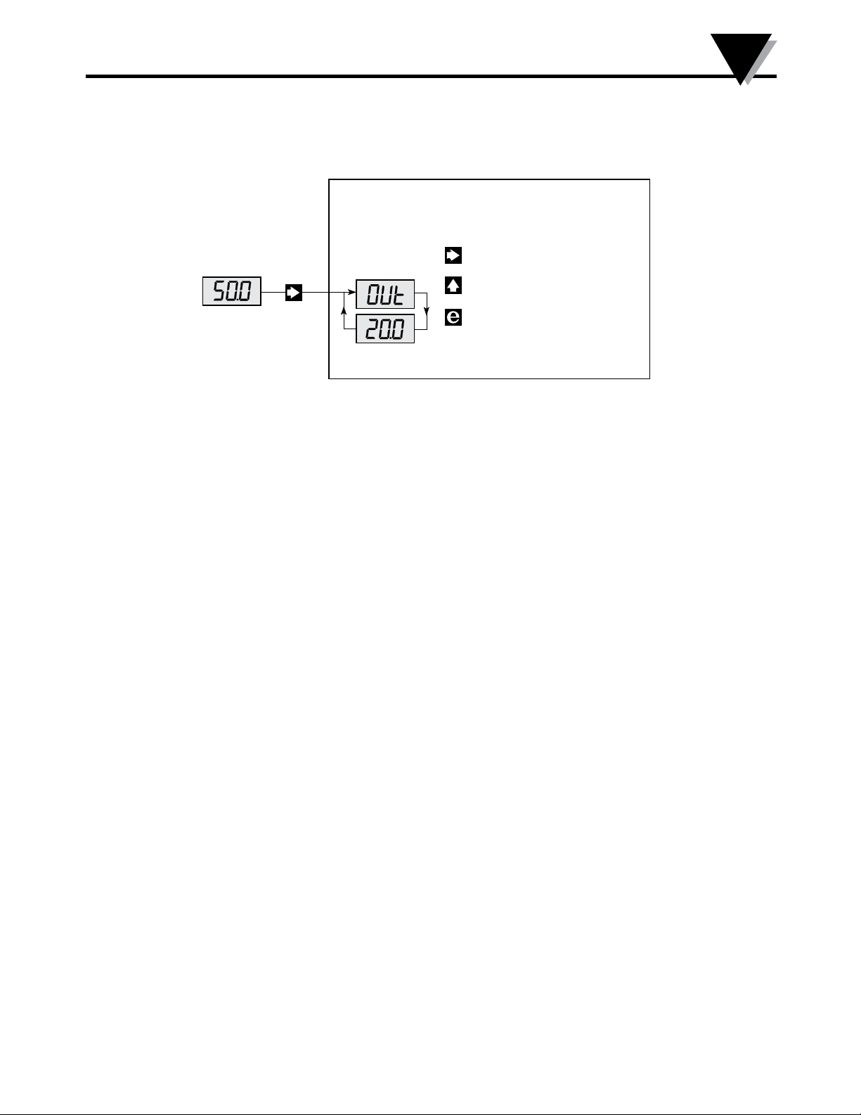
Section 4.2 -Programming/Operating the function keys cont.
Front Settin g
5.2 EFS/dFS - enabl e / disabl e front setting
Downcoun t ramp
4
0.0
1.0 In - SETTING OF INPUT SPAN
1.1 InL - Setting of
0% input value
Valid selections are -40...100 mV.
1.2 InH - Setting of
100% input value
Valid selections are -40...100 mV.
1.3 InO - Setting of
The analogue output follows the set input span on a linear basis {1.1 - InL
and 1.2 - InH} with a limit at
When the input signal is < or > the set input span, the display will track
this and show
overrange
-xx or xxx% until the input begins to limit.
The overrange is set in % of
does not begin to limit within the percentage overrange, neither below
nor above the set input span, provided that the input span – overrange is
within the signal range -40 to 100 mV.
Setting the overrange does not affect the analogue output.
If the overrange measure
ment is to be included in the analogue output
signal, the output signal for the set input span must be selected to
provide room for the overrange within the signal range of the output
(0...20 mA / 0...10 VDC).
Upcoun t ramp
Store and exit front setting
20.5 mA (normally approx. 103% input span).
the input span and guaran tees that the input
Example:
A signal of
It must
analogue output of
shows 150%.
5...15 mV corresponds to a weight of 0...1000 kilo.
be possible to detect a 50% overrange of the scale on the
the mV transmitter at the same time as the display
The following settings will result in the requested function with an
output signal of
4...19.9 mA:
Input: InL = 5.0, InH = 15.0, InO = 50.0
Output: OL = 4.0, OH = 14.6, UI = 002
Please note
10.6 mA which, with an addition of
that the output span has been set to (14.6 mA - 4.0 mA) =
50%, will result in a span of (10.6 +
(10.6 * 50/100)) = 15.9 mA.
12
Page 13

5
Description of Functions
Section 5.1 - CAL - Setting of Calibration values
The calibration function is a relative calibration, i.e. the percentage input value for the low
calibration must be entered in submenu 3.1{CLO - Calibration Low}, and the percentage input
value for the high calibration must be entered in submenu 3.2 {CHI - Calibration High}. The
entered percen tages are used for calculating the actual input span.
When {CHI - Calibration High} is activated, the calculation is made using the percentages in
{CLO} and {CHI}.
Section 5.2 - CLO - Setting of low calibration value
Key . Enter the calibration value by the and keys.
Connect the low calibration signal to the input. Activate the and keys simultaneously.
Section 5.3 - CHI - Setting of Calibration value
Key . Enter the calibration value by the and keys.
Connect the low calibration signal to the input. Activate the and keys simultaneously.
The input span is now calcu lated using the entered calibration values. The mV values are read
from the submenus {1.1 - InL and 1.2 - InH}.
Section 5.4 - OUt - Setting of Analogue output
4.1 : OL - Low - 0% setting of analogue output
Valid selections are current in the range 0.0...20.0 mA or voltage in the range 0.0...10.0 VDC.
4.2 : OH - High - 100% setting of analogue output
Valid selections are current in the range 0.0...20.0 mA or voltage in the range 0.0...10.0 VDC.
4.3 : UI - Selection of current or voltage output
See the hardware programming for correct jumper setting. Possible selections are:
001 = Current output in the range 0...10 mA
002 = Current output in the range 0...20 mA
003 = Voltage output in the range 0...500 mV
004 = Voltage output in the range 0...1000 mV
005 = Voltage output in the range 0...5 V
006 = Voltage output in the range 0...10 V
4.4 : rEP - Setting of response time
Valid selections are 0.0...999 s. If the set response time is < 0.06 s, the response time will be 0.06 s
13
Page 14

Description of Functions
Section 5.5 - tAR - Selection of taring type
Possible selections are tLO - 0% taring enable, tHI - 100% taring enable, or dtA - taring
disabled.
If tLO is selected, activating the 3 key for more than 2 s or activating the digital input
will tare the input signal to 0%.
If tHI is selected, activating 3 for more than 2 s or activating the digital input will tare
the input signal to 100% (max.).
The 2 types of taring can be used for filling or emptying respect ively.
If a 0% (tLO) taring is selected, the analogue input will show 0% after taring. If a 100%
(tHI) taring is selec ted, the input will show 100% after taring corresponding to tara +
net weight = gross weight.
Taring is either from the digital input or from front
Section 5.6 - dIN - Selection of digital input type
5
Possible selections are:
PnP = mechanical contact or open collector transistor connected to +24 VDC.
nPn = mechanical contact or open collector transistor connected to gnd.
Section 5.7 - SUP - Setting of supply voltage for transducer
Valid selections are 5.0...13 VDC.
Section 5.8 - PAS - Setting of Password
Key 2. When the password is 040, changes can be made in all menu points. When the
password is <> 040, programming is blocked in all menu points, but access is open for
reading the settings. Enter the password by the 3 and 1 keys.
When the password is correct, activate 3 and 1 simultaneously. Valid selections are
0...999.
Section 5.9 - Frq - Selection of common mode frequency suppression
Possible selections are 50 or 60 Hz.
14
Page 15
6
Displays
Section 6.1 - Displays
Programmable displays with a wide selection of
inputs and outputs for display of temperature, volume
and weight, etc. Feature linearization, scaling, and
difference measurement functions for programming
via PReset software.
6.2 - EX Interfaces
Interfaces for analog and digital signals as well as
HART
frequency signals and control systems in Ex zone 0, 1
& 2 and for some devices in zone 20, 21 & 22.
®
signals between sensors/I/P converters /
6.3 - Isolation
Galvanic isolators for analog and digital signals as
well as HART
both loop powered and universal isolators featuring
linearization, inversion, and scaling of output signals.
®
signals. A wide product range with
15
Page 16
6.4 - Temperature
A wide selection of transmitters for DIN form B
mounting and DIN rail devices with analog and
digital bus communication ranging from applicationspecific to universal transmitters.
6.5 - Universal
PC or front programmable devices with universal
options for input, output and supply. This range
offers a number of advanced features such as process
calibration, linearization and auto-diagnosis.
Diagrams
6
16
Page 17

WARRANTY/DISCLAIMER
OMEGA ENGINEERING, INC. warrants this unit to be free of defects in materials and workmanship for a
period of 13 months from date of purchase. OMEGA’s WARRANTY adds an additional one (1) month grace
period to the normal one (1) year product warranty to cover handling and shipping time. This ensures
that OMEGA’s customers receive maximum coverage on each product.
If the unit malfunctions, it must be returned to the factory for evaluation. OMEGA’s Customer Service
Department will issue an Authorized Return (AR) number immediately upon phone or written request.
Upon examination by OMEGA, if the unit is found to be defective, it will be repaired or replaced at no
charge. OMEGA’s WARRANTY does not apply to defects resulting from any action of the purchaser,
including but not limited to mishandling, improper interfacing, operation outside of design limits,
improper repair, or unauthorized modification. This WARRANTY is VOID if the unit shows evidence of
having been tampered with or shows evidence of having been damaged as a result of excessive corrosion;
or current, heat, moisture or vibration; improper specification; misapplication; misuse or other operating
conditions outside of OMEGA’s control. Components in which wear is not warranted, include but are not
limited to contact points, fuses, and triacs.
OMEGA is pleased to offer suggestions on the use of its various products. However,
OMEGA neither assumes responsibility for any omissions or errors nor assumes liability for
any damages that result from the use of its products in accordance with information provided
by OMEGA, either verbal or written. OMEGA warrants only that the parts manufactured by the
company will be as specified and free of defects. OMEGA MAKES NO OTHER WARRANTIES OR
REPRESENTATIONS OF ANY KIND WHATSOEVER, EXPRESSED OR IMPLIED, EXCEPT THAT OF
TITLE, AND ALL IMPLIED WARRANTIES INCLUDING ANY WARRANTY OF MERCHANTABILITY
AND FITNESS FOR A PARTICULAR PURPOSE ARE HEREBY DISCLAIMED. LIMITATION OF
LIABILITY: The remedies of purchaser set forth herein are exclusive, and the total liability of
OMEGA with respect to this order, whether based on contract, warranty, negligence,
indemnification, strict liability or otherwise, shall not exceed the purchase price of the
component upon which liability is based. In no event shall OMEGA be liable for
consequential, incidental or special damages.
CONDITIONS: Equipment sold by OMEGA is not intended to be used, nor shall it be used: (1) as a “Basic
Component” under 10 CFR 21 (NRC), used in or with any nuclear installation or activity; or (2) in medical
applications or used on humans. Should any Product(s) be used in or with any nuclear installation or
activity, medical application, used on humans, or misused in any way, OMEGA assumes no responsibility
as set forth in our basic WARRANTY/DISCLAIMER language, and, additionally, purchaser will indemnify
OMEGA and hold OMEGA harmless from any liability or damage whatsoever arising out of the use of the
Product(s) in such a manner.
RETURN REQUESTS/INQUIRIES
Direct all warranty and repair requests/inquiries to the OMEGA Customer Service Department. BEFORE
RETURNING ANY PRODUCT(S) TO OMEGA, PURCHASER MUST OBTAIN AN AUTHORIZED RETURN (AR)
NUMBER FROM OMEGA’S CUSTOMER SERVICE DEPARTMENT (IN ORDER TO AVOID PROCESSING
DELAYS). The assigned AR number should then be marked on the outside of the return package and on any
correspondence.
The purchaser is responsible for shipping charges, freight, insurance and proper packaging to prevent
breakage in transit.
FOR WARRANTY RETURNS, please have the
following information available BEFORE contacting
OMEGA:
1. Purchase Order number under which the product
was PURCHASED,
2. Model and serial number of the product under
warranty, and
3. Repair instructions and/or specific problems
relative to the product.
OMEGA’s policy is to make running changes, not model changes, whenever an improvement is possible. This affords our
customers the latest in technology and engineering.
OMEGA is a trademark of OMEGA ENGINEERING, INC.
© Copyright 2018 OMEGA ENGINEERING, INC. All rights reserved. This document may not be copied, photocopied,
reproduced, translated, or reduced to any electronic medium or machine-readable form, in whole or in part, without the prior
written consent of OMEGA ENGINEERING, INC.
FOR NON-WARRANTY REPAIRS, consult
OMEGA for current repair charges. Have
the following information available BEFORE
contacting OMEGA:
1. Purchase Order number to cover the COST
of the repair,
2. Model and serial number of the product, and
3. Repair instructions and/or specific problems
relative to the product.
Page 18

Where Do I Find Everything I Need for
Process Measurement and Control?
OMEGA…Of Course!
Shop online at omega.com
TEMPERATURE
MU
Thermocouple, RTD & Thermistor Probes, Connectors,
Panels & Assemblies
MU
Wire: Thermocouple, RTD & Thermistor
MU
Calibrators & Ice Point References
MU
Recorders, Controllers & Process Monitors
MU
Infrared Pyrometers
PRESSURE, STRAIN AND FORCE
MU
Transducers & Strain Gages
MU
Load Cells & Pressure Gages
MU
Displacement Transducers
MU
Instrumentation & Accessories
FLOW/LEVEL
MU
Rotameters, Gas Mass Flowmeters & Flow Computers
MU
Air Velocity Indicators
MU
Turbine/Paddlewheel Systems
MU
Totalizers & Batch Controllers
pH/CONDUCTIVITY
MU
pH Electrodes, Testers & Accessories
MU
Benchtop/Laboratory Meters
MU
Controllers, Calibrators, Simulators & Pumps
MU
Industrial pH & Conductivity Equipment
DATA ACQUISITION
MU
Communications-Based Acquisition Systems
MU
Data Logging Systems
MU
Wireless Sensors, Transmitters, & Receivers
MU
Signal Conditioners
MU
Data Acquisition Software
HEATERS
MU
Heating Cable
MU
Cartridge & Strip Heaters
MU
Immersion & Band Heaters
MU
Flexible Heaters
MU
Laboratory Heaters
ENVIRONMENTAL
MONITORING AND CONTROL
MU
Metering & Control Instrumentation
MU
Refractometers
MU
Pumps & Tubing
MU
Air, Soil & Water Monitors
MU
Industrial Water & Wastewater Treatment
MU
pH, Conductivity & Dissolved Oxygen Instruments
M5688/1018
 Loading...