

Page 1
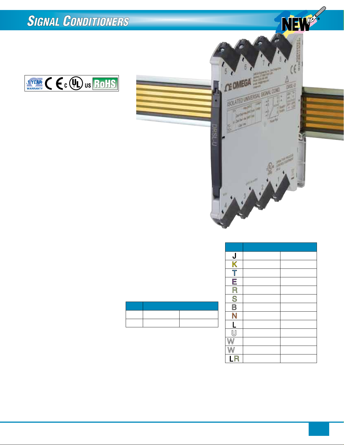
Isolated Universal Input DIN Rail Signal Conditioner
U
W3W
DRSL-U
Listed
U Universal Input–Accepts
Thermocouple, RTD, Linear
Resistance, Potentiometer,
Voltage or Current Input
U Easily Configured
Using DRSL-DISPLAY
Programming Interface
U Slimline Housing–
Only 6 mm (0.24") Wide
U High Accuracy
U Fast Response Time
U Excellent EMC Performance and
50/60 Hz Noise Suppression
The DRSL-U isolated universal
input DIN rail signal conditioner
provides a competitive choice in
terms of both price and technology
for galvanic isolation of process
signals to SCADA systems or
PLC equipment. The DRSL-U
accepts thermocouple, RTD, linear
resistance, potentiometer, voltage
or current input and converts these
signals to linear voltage or current
output. The unit offers isolation
between input, output and supply,
provides surge suppression and
protects control systems from
transients and noise. The DRSL-U
also eliminates ground loops and
can be used for measuring floating
signals. Low power consumption
facilitates DIN rail mounting without
the need for any air gap. The
DRSL-U is easily configured by using
the DRSL-DISPLAY programming
interface in conjunction with the
DRSL-ADAPTOR configuration
adaptor. The DRSL-DISPLAY has
a 4 line LCD display with scrolling
help text in 7 languages (English,
French, German, Italian, Spanish,
Danish and Swedish) which guides
the user through all the configuration
steps. The DRSL-U is designed
with electronic hardware switches,
consequently it is not necessary to
open the device to set any internal
DIP-switches.
When the input is configured
for 2-wire transmitter mode,
the DRSL-U provides the
current loop supply voltage.
The unit operates over a
wide temperature range from
-25 to 70°C (-13 to 158°F).
SPECIFICATIONS
INPUT
RTD Input
Input Type: Pt10, Pt20, Pt50, Pt100,
Pt200, Pt250, Pt300, Pt400, Pt500,
Pt1000, Ni50, Ni100, Ni120, Ni1000,
linear resistance, potentiometer
Cable Resistance Per Wire: 50 Ω max
Sensor Current: 0.2 mA nominal
Effect of Sensor Cable Resistance
(3-Wire/4-Wire RTD): <0.002 Ω / Ω
Sensor Error Detection: Yes
Short Circuit Detection: <15 Ω
RTD Input Types and Ranges
Type Range
Pt100
Ni100
Linear Resistance Input Range:
0 to 10,000 Ω
Potentiometer Input Range: 10 to 100 kΩ
Thermocouple Input
Input Types: J, K, T, E, R, S, B, N, L,
U, W3, W5, LR
Cold Junction Compensation
(CJC) Via Internally Mounted
Sensor: ±(2.0°C + 0.4°C * ∆t)
(∆t = internal temperature-ambient
temperature)
Sensor Error Detection: Yes
Sensor Error Current: 2 μA nominal
(when detecting)
DRSL-U and
DRSL-PWR-RAIL
shown actual size.
-200 to 850°C -328 to 1562°F
-60 to 250°C -76 to 482°F
Thermocouple Input
Types and Ranges
Type Range
J
-100 to 1200°C -148 to 2192°F
K
-180 to 1372°C -292 to 2502°F
T
-200 to 400°C -328 to 752°F
E
-100 to 1000°C -148 to 1832°F
R
-50 to 1760°C -58 to 3200°F
S
-50 to 1760°C -58 to 3200°F
B
N
L
U
W3
W5
LR
0 to 1820°C 32 to 3308°F
-180 to 1300°C -292 to 2372°F
-200 to 900°C -328 to 1652°F
-200 to 600°C -328 to 1112°F
0 to 2300°C 32 to 4172 °F
0 to 2300°C 32 to 4172°F
5
-200 to 800°C -328 to 1472°F
Current Input
Measurement Range: 0 to 20 mA
Programmable Measurement
Ranges: 0 to 20 mA and 4 to 20 mA
Input Resistance: 20 Ω + PTC 50 Ω
nominal
2-Wire Transmitter Supply:
>15 V/20 mA
1
Page 2
Voltage Input
Measurement Range: 0 to 12V
Programmable Measurement
Ranges: 0 to 1V, 0.2 to 1V, 0 to 5V,
1 to 5V, 0 to 10V, 2 to 10V
Input Resistance: 10 MΩ nominal
Basic Accuracy Values
Temperature
Input Type Accuracy
mA
0 to 1V,
0.2 to 1V
0 to 5V,
1 to 5V,
0 to 10V,
2 to 10V
Pt100, Pt200,
Pt1000
Pt500, Ni100,
Ni120, Ni1000
Pt50, Pt400,
Ni50
Pt250, Pt300
Pt20
Pt10
Thermocouple
Types
E, J, K, L,
N, T, U
Thermocouple
Types R, S,
W3, W5, LR
Thermocouple
Type B, 160
to 400°C
Thermocouple
Type B,
400 to
1820°C
≤±16 μA ≤±1.6 μA/°C
≤±0.8 mV ≤±0.08 mV/°C
≤±8 mV ≤±0.8 mV/°C
≤±0.2°C ≤±0.02°C/°C
≤±0.3°C ≤±0.03°C/°C
≤±0.4°C ≤±0.04°C/°C
≤±0.6°C ≤±0.06°C/°C
≤±0.8°C ≤±0.08°C/°C
≤±1.4°C ≤±0.14°C/°C
≤±1.0°C ≤±0.1°C/°C
≤±2.0°C ≤±0.2°C/°C
≤±4.5°C ≤±0.45°C/°C
≤±2.0°C ≤±0.2°C/°C
Coefficient
OUTPUT
Current Output
Signal Range: 0 to 20 mA (span)
Programmable Signal Ranges:
0 to 20 mA, 4 to 20 mA, 20 to 0 mA
and 20 to 4 mA
Load: 20 mA/600 Ω/15 Vdc max
Load Stability: ≤0.01% of span/100 Ω
(span=currently selected
measurement range)
Range Limits
(NAMUR NE43 Out of Range):
Below 3.8 mA or above 20.5 mA for
4 to 20 mA output; 0 mA or above
20.5 mA for 0 to 20 mA output
Sensor Error Detection:
Below 3.5 mA or above 23 mA for
4 to 20 mA output; 0 mA or above
23 mA for 0 to 20 mA output
Current Limit: ≤28 mA
Voltage Output
Signal Range: 0 to10 Vdc
Programmable Signal Ranges:
0 to 1V, 0.2 to 1V, 0 to 5V, 1 to 5V,
0 to 10V, 2 to 10V, 1 to 0.2V, 1 to 0V,
5 to 1V, 5 to 0V, 10 to 2V
and 10 to 0V
Load (Min): >10 kΩ
GENERAL
Supply Voltage: 16.8 to 31.2 Vdc via
power rail or connectors
Power Consumption: 1.2 W max
Internal Consumption: 0.4 W
typical, 0.65 W max
Isolation: Input/output/power
Isolation Voltage (Test): 2.5 kVac
Isolation Voltage (Working):
300 Vac
Status LED: Green LED indicates
operational status of the unit and
input sensor
Normal Operation: Flashes for
15 ms at 13 Hz rate
Sensor Error: Flashes for 15 ms
at 1 Hz rate
Hardware Failure: LED off
Signal/Noise Ratio: >60 dB
Response Time (0 to 90%, 100 to
10%) for Temperature Input: ≤1 s
Response Time (0 to 90%, 100 to
10%) for mA/V input: ≤400 ms
E
D BF
+
+
-
-
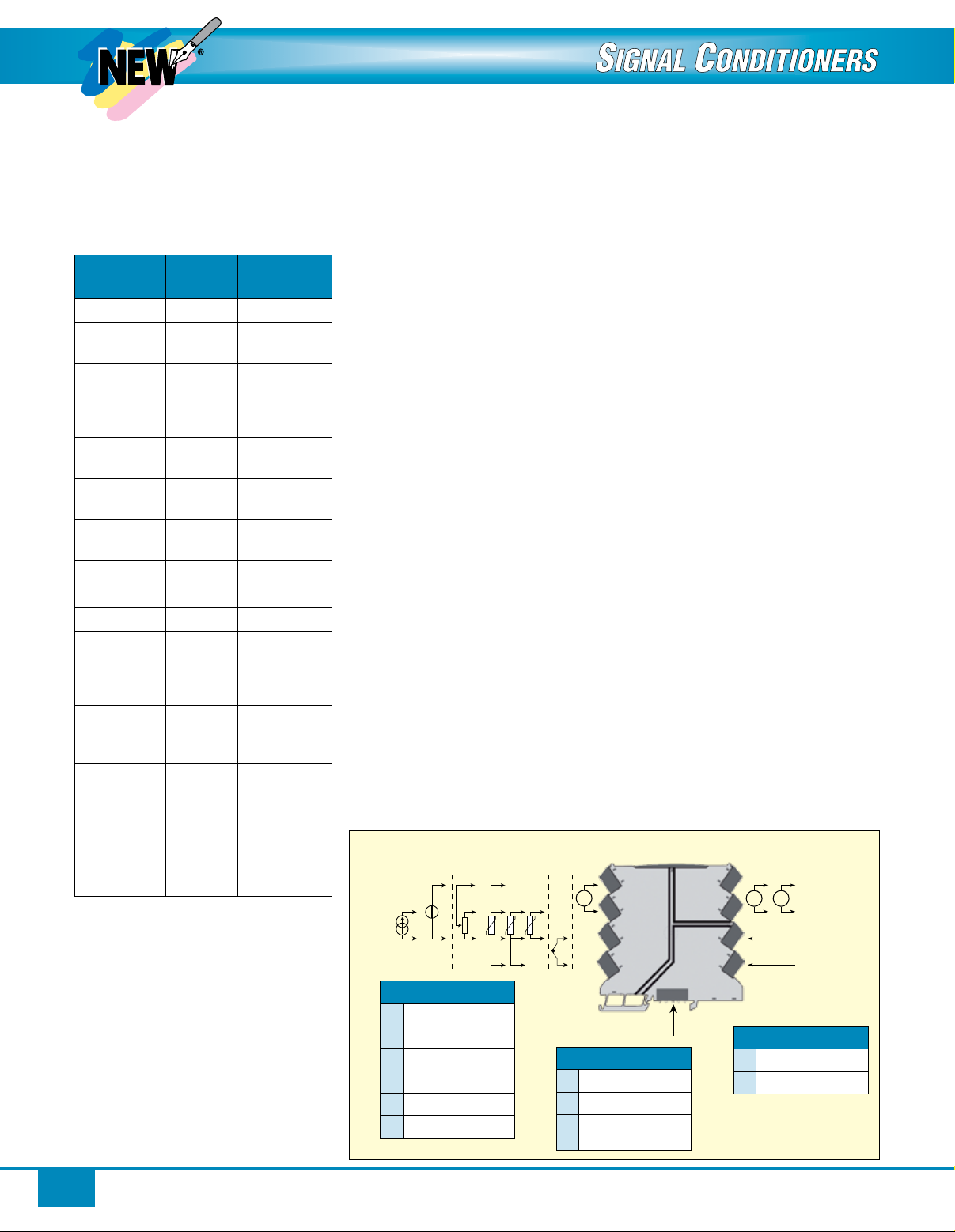
Input signals
A
B
C
D
E
F
Current 1
TC
RTD
Potentiometer
Voltage
Current 2
C
CONNECTIONS
A
+
4
Tx
-
3
I
J
K
2
Supply
connections
-
+
Accuracy: Absolute accuracy
or accuracy from table above
(whichever is greater)
Absolute Accuracy:
All Input Types: ≤±0.1% of span
(selected input range)
Temperature Coefficient:
All Input Types: ≤± 0.01% of
span/°C
EMC Immunity Influence: <±0.5%
of span
Extended EMC Immunity NAMUR
NE 21, A Criterion, Burst: <±1% of
span (span = selected input range)
ENVIRONMENTAL
Operating Temperature: -25 to 70°C
(-13 to 158°F)
Storage Temperature: -40 to 85°C
(-40 to 185°F)
Calibration Temperature: 20 to
28°C (68 to 82°F)
Relative Humidity: 0 to 95% RH
non-condensing
Protection Degree: IP20
Installation Area: Pollution degree
2 and measurement/overvoltage
category II
MECHANICAL
Dimensions: 113 H x 6.1 W x 115 mm D
(4.4 x 0.24 x 4.5")
Weight: 70 g (0.15 lb) approx
DIN Rail Type: DIN EN 60715 - 35 mm
2
Wire Size: 0.13 x 2.5 mm
/AWG 26
to 12 stranded wire
Screw Terminal Torque: 0.5 Nm
H
G
+
+
Supply
5
mA
-
6
I
7
J
81
Output signals
G
H
V
-
Current
Voltage
Input Output
Input
Supply
81 82 83 84 85
Supply +
Supply -
Power rail
Output
K
2
Page 3
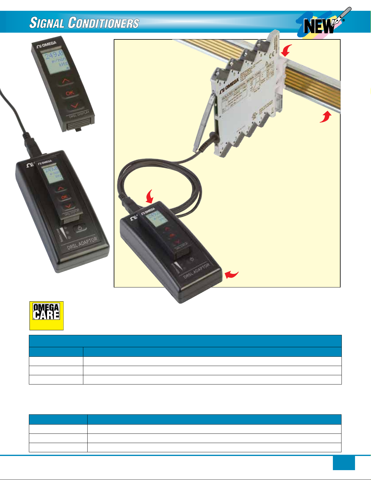
DRSL-DISPLAY
programming
interface.
DRSL-ADAPTOR
docking station.
DRSL-DISPLAY
programming interface
inserted into DRSL-ADAPTOR
docking station connected to
DRSL-U module.
DRSL-DISPLAY
DRSL-MOD-STOP.
DRSL-PWR-RAIL
DRSL-ADAPTOR
SM
SM
extended warranty program is
SM
covers parts, labor and equivalent loaners.
Extended Warranty
Program
OMEGACARE
available for models shown on this page. Ask your sales
representative for full details when placing an order.
OMEGACARE
To Order
Model No. Description
DRSL-U
DRSL-DISPLAY
DRSL-ADAPTOR
Ordering Example: DRSL-U isolated universal input DIN rail signal conditioner, DRSL-DISPLAY display/front communication interface,
DRSL-ADAPTOR configuration adaptor/docking station, DRSL-PWR-RAIL power rail, DRSL-PCU power connector unit,
DRSL-MOD-STOP module stop and OCW-1, OMEGACARE SM extends standard 1-year warranty to a total of 2 years.
Accessories
Model. No. Description
DRSL-PWR-RAIL
DRSL-PCU
DRSL-MOD-STOP
Isolated universal input signal conditioner
Display/programming front communication interface for DRSL-U (plugs into DRSL-ADAPTOR)
Configuration adaptor/docking station for use with DRSL-DISPLAY programming interface
Power rail (with cover and two end covers, one right hand and one left hand), 1 m (3.3') length
Power connector unit, 24 Vdc/2.5 A output to power rail
Module stop (screwed onto power rail to support and hold mounted devices)
3
 Loading...