

Page 1
Installationsvejledningen omfatter følgende produkter:
DK UK FR DE
DRSL-DC1, DRSL-DC2, DRSL-DC3, DRSL-DC4, DRSLSP1, DRSL-SP2, DRSL-SP3, DRSL-U, DRSL-LPI, DRSLLPO, DRSL-PCU.
GENERELT
må kun benyttes som beskrevet i det følgende. Installationsvejledningen skal stu deres omhyggeligt, før modulet tages i brug. Kun kvalificeret perso nale (teknikere)
må installere dette modul. Hvis modulet ikke benyttes
som beskrevet i denne installationsvejled ning, så forringes modulets beskyttelsesforanstaltninger. Der må
ikke tilsluttes farlig spænding til modulet, før dette er
fastmonteret.
Reparation af modulet må kun foretages af OMEGA.
FARLIG
SPÆNDING
ADVARSEL
Modtagelse og udpakning
Udpak modulet uden at beskadige det. Kontrollér ved
modtagelsen, at modultypen svarer til den bestilte. Indpakningen bør følge modulet, indtil dette er monteret
på blivende plads.
Miljøforhold
Undgå direkte sollys, kraftigt støv eller varme, mekaniske rystelser og stød, og udsæt ikke modulet for regn
eller kraftig fugt. Om nødvendigt skal opvarmning,
ud over de opgivne grænser for omgivelsestemperatur, forhindres ved hjælp af ventilation. Alle moduler
kan anvendes i Måle- / overspændingskategori II og
Forureningsgrad 2. Modulet er designet til at være sikkert mindst op til en højde af 2000 m.
Installation
Installation og tilslutning af modulet skal følge landets
gældende regler for installation af elektrisk materiel
bl.a. med hensyn til lednings tværsnit, for-sikring og
placering.
Beskrivelse af indgang / udgang og forsyningsforbindelser findes i installationsvejledningen og på
sideskiltet.
Modulet er forsynet med skrueterminaler og skal
forsynes fra en dobbeltisoleret / forstærket isoleret spændingsforsyning. En aryder placeres let
tilgængeligt og tæt ved modulet. Aryderen skal
mærkes således, at der ikke er tvivl om, at den aryder
spændingen til modulet.
SYSTEM DRSL skal installeres på DIN-skinne iht. EN
60715.
UL-installation
Brug kun 60/75°C kobberledninger.
Ledningskvadrat
UL fil-nummer .................................... E70366
Modulet er af typen Open Type Listed Process Control
Equipment. For at undgå at personer kommer til skade
ved berøring af strømførende dele, skal modulet monteres i et kabinet.
Spændingsforsyningen skal være i overensstemmelse
med NEC Class 2, som beskrevet i ”National Electrical
®
(ANSI / NFPA 70)”.
Code
ADVARSEL
For at undgå faren for elektriske stød og
brand skal sikkerhedsreglerne overholdes,
og vejledningerne skal følges. Specifikationerne må ikke overskrides, og modulet
I applikationer hvor farlig spænding er
tilsluttet modulet ind-/udgange, skal det
sikres, at der er tilstrækkelig afstand eller
isolation mellem ledninger, klemmer og
hus til omgivelserne (inkl. nabomoduler) til
at opretholde beskyttelsen mod elektriske
stød.
Stikket bag frontpladen på DRSL-U har
forbindelse til indgangsklemmer, hvor der
kan forekomme farlige spændinger.
Risiko for elektrostatisk ladning. For at
forhindre risikoen for eksplosion pga.
elektrostatisk opladning af kabinettet må
modulerne kun håndteres, når området
er sikkert, eller når der er taget passende
forholdsregler mod elektrostatiske udladninger.
SIKKERHEDSREGLER
................................ AWG 26-12
This installation guide covers the following products:
DRSL-DC1, DRSL-DC2, DRSL-DC3, DRSL-DC4, DRSLSP1, DRSL-SP2, DRSL-SP3, DRSL-U, DRSL-LPI, DRSLLPO, DRSL-PCU.
WARNING
To avoid the risk of electric shock and fire,
the safety instructions of this guide must be
observed and the guidelines followed. The
GENERAL
specifications must not be exceeded, and the
device must only be applied as described in the following.
Prior to the commissioning of the device, this inst
allation guide must be examined carefully. Only qualified
personnel (technicians) should install this device. If the
equipment is used in a manner not specified by the
manufacturer, the protection provided by the equipment
may be impaired. Until the device is fixed, do not connect
hazardous voltages to the device.
Repair of the device must be done by OMEGA only.
In applications where hazardous voltage
is connected to in-/outputs of the device,
sucient spacing or isolation from wires,
HAZARD-OUS
terminals and enclosure - to surroundings
VOLTAGE
(incl. neighbouring devices), must be
ensured to maintain protection against
electric shock.
The connector behind the front cover of
DRSL-U is connected to the input terminals
on which dangerous voltages can occur.
Potential electrostatic charging hazard.
To avoid the risk of explosion due to
electrostatic charging of the enclosure,
WARNING
do not handle the units unless the area
is known to be safe, or appropriate safety
measures are taken to avoid electrostatic
discharge.
SAFETY INSTRUCTIONS
Receipt and unpacking
Unpack the device without damaging it. The packing
should always follow the device until this has been
permanently mounted. Check at the receipt of the
device whether the type corresponds to the one
ordered.
Environment
Avoid direct sunlight, dust, high temperatures,
mechanical vibrations and shock, as well as rain and
heavy moisture. If necessary, heating in excess of
the stated limits for ambient temperatures should
be avoided by way of ventilation. All devices can be
used for Measurement / Overvoltage Category II and
Pollution Degree 2. The module is designed to be safe
at least under an altitude up to 2 000 m.
Mounting
Mounting and connection of the device should comply
with national legislation for mounting of electric
materials, i.e. wire cross section, protective fuse, and
location. Descriptions of input / output and supply
connections are shown in this installation guide and on
the side label.
The device is provided with field wiring terminals and
shall be supplied from a Power Supply having double /
reinforced insulation. A power switch should be easily
accessible and close to the device. The power switch shall
be marked as the disconnecting unit for the device.
DRSL devices must be mounted on a DIN rail according
to EN 60715.
UL installation
Use 60/75°C copper conducters only.
Wire size
............................................... AWG 26-12
UL file number.................................... E70366
The device is an Open Type Listed Process Control
Equipment. To prevent injury resulting from
accessability to live parts the equipment must be
installed in an enclosure.
The power Supply unit must comply with NEC Class 2, as
described by the National Electrical Code
70).
®
(ANSI / NFPA
Ce guide d’installation couvre les produits suivants :
DRSL-DC1, DRSL-DC2, DRSL-DC3, DRSL-DC4, DRSL-SP1,
DRSL-SP2, DRSL-SP3, DRSL-U, DRSL-LPI, DRSL-LPO,
DRSL-PCU.
INFORMA-
TIONS
GENERALES
de ce module, telles qu’elles sont décrites dans ce
guide. Il est nécessaire de lire ce guide attentivement
avant de mettre ce module en marche. L’installation
de ce module est réservée à un personnel qualifié
(techniciens). Si la méthode d’utilisation de l’équipement
dière de celle décrite par le fabricant, la protection
assurée par l’équipement risque d’être altérée. Tant que
le module n’est pas fixé, ne le mettez par sous tensions
dangereuses.
Seule OMEGA est autorisée à réparer le module.
TENSION
DANGE-
REUSE
AVER-
TISSEMENT
AVERTISSEMENT
Pour éviter les risques d’électrocution et
d’incendie, conformez-vous aux consignes
de sécurité et suivez les instructions
mentionnées dans ce guide. Vous devez
vous limiter aux spécifications indiquées
et respecter les instructions d’utilisation
En cas d’utilisation ou une tension
dangereuse est connectée aux entrée/
sorties du module, veillez à avoir une
distance ou une isolation susante entre
les fils, les borniers et le boîtier par rapport
aux environs (y inclus les appareils voisins)
pour maintenir la protection contre les chocs
électriques.
Le bornier derrière la face avant du module
DRSL-U est raccordé à l’entrée du module
sur laquelle peuvent apparaître des tensions
dangereuses.
Danger potentiel de charge électrostatique.
Pour s’aranchir du risque d’explosion lié
à la charge électrostatique du boîtier, ne
pas manipuler l’appareil sauf si la zone est
réputée être sûre, ou si des mesures de
sécurité appropriées sont prises pour éviter
les décharges électrostatiques.
CONSIGNES DE SECURITE
Réception et déballage
Déballez le module sans l’endommager. Il est recommandé
de conserver l’emballage du module tant que ce dernier n’est
pas définitivement monté. A la réception du module, vérifiez
que le type de module reçu correspond à celui que vous avez
commandé.
Environnement
N’exposez pas votre module aux rayons directs du
soleil et choisissez un endroit à humidité modérée et à
l’abri de la poussière, des températures élevées, des
chocs et des vibrations mécaniques et de la pluie. Le
cas échéant, des systèmes de ventilation permettent
d’éviter qu’une pièce soit chauée au-delà des limites
prescrites pour les températures ambiantes. Tous
les modules peuvent être installés dans catégorie
de mesure / surtension Il et degré de pollution 2.
Ce module est conçu pour fonctionner en toute sécurité
sous une altitude inférieure à 2000 m.
Montage
Le montage et le raccordement du module doivent être
conformes à la législation nationale en vigueur pour
le montage de matéri aux électriques, par ex emple,
diamètres des fils, fusibles de protection et implantation
des modules. Les connexions des alimentations et des
entrées / sorties sont décrites dans ce guide et sur
l’étiquette de la face latérale du module. Les appareils
sont équipés de borniers à vis et doivent être raccordés
à une alimentation qui a une double isolation renforcée.
L’interrupteur doit être à proximité du module et facile
d’accès. Ce bouton doit être étiqueté avec la mention :
peut couper la tension du module. Il convient de monter
l’appareil SYSTEM DRSL sur un rail DIN en se conformant à
la norme EN 60715.
Installation UL
N’utilisez que de conducteurs de cuivre 60/75°C.
Taille des fils
No du fichier UL .................................... E70366
L’appareil est considéré comme équipement avec des
parties sous tension accessibles. Pour prévenir les
blessures résultantes d’un accès aux parties sous tension,
l’équipement doit être installé dans une enceinte.
L’alimentation doit conformer aux exigences de NEC
Class 2, comme spécifié dans le « National Electrical Code®
(ANSI / NFPA 70) ».
.......................................... AWG 26-12
Diese Installationsanleitung umfasst die folgenden Produkte:
DRSL-DC1, DRSL-DC2, DRSL-DC3, DRSL-DC4, DRSL-SP1,
DRSL-SP2, DRSL-SP3, DRSL-U, DRSL-LPI, DRSL-LPO,
DRSL-PCU.
ALLGE-
MEINES
nicht überschritten werden, und das Gerät darf nur
gemäß folgender Beschreibung benutzt werden. Diese
In stallationsanleitung ist sorgfältig durchzulesen, ehe
das Gerät in Gebrauch genommen wird. Nur qualifizierte
Personen (Techniker) dürfen dieses Gerät installieren.
Wenn das Gerät nicht wie in dieser Installationsanleitung
beschrieben benutzt wird, werden die Schutzeinrichtungen
des Gerätes beeinträchtigt. Vor dem abgeschlossenen festen Einbau des Gerätes darf daran keine gefährliche Spannung angeschlossen werden. Reparaturen des Gerätes
GEFÄHR-
LICHE
SPANNUNG
WARNUNG
Empfang und Auspacken
Packen Sie das Gerät aus, ohne es zu beschädigen, und
kontrollieren Sie beim Empfang, ob der Gerätetyp Ihrer
Bestellung entspricht. Die Verpackung sollte beim Gerät
bleiben, bis dieses am endgültigen Platz montiert ist.
Umgebungsbedingungen
Direkte Sonneneinstrahlung, starke Staubentwicklung
oder Hitze, mechanische Erschütterungen und Stöße sind
zu vermeiden; das Gerät darf nicht Regen oder starker
Feuchtigkeit ausgesetzt werden. Bei Bedarf muss eine
Erwärmung, welche die angegebenen Grenzen für die
Umgebungstemperatur überschreitet, mit Hilfe eines
Kühlgebläses verhindert werden. Alle Geräte können für
Mess- / Überspannungskategorie II und Verschmutzungsgrad 2 benutz werden. Das Gerät ist so konzipiert, dass es
auch in einer Einsatzhöhe von bis zu 2000 m noch sicher
funktioniert.
Installation
Die Installation und der Anschluss des Gerätes haben in
Über einstimmung mit den geltenden Regeln des jeweiligen
Landes bez. der Installation elektrischer Apparaturen zu erfolgen, u.a. bezüglich Leitungsquerschnitt, (elektrischer)
Vor-Absicherung und Positionierung. Eine Beschreibung
von Eingangs- / Ausgangs- und Versorgungsanschlüssen
befindet sich in dieser Installations anleitung und auf dem
Typenschild.
Das Gerät ist mit Feldverdrahtungsklemmen ausgestattet
und wird von einem Netzteil mit doppelter / verstärkter
Isolierung versorgt. Der Netzschalter sollte leicht zugänglich
und in der Nähe des Gerätes sein. Der Netzschalter sollte mit
einem Schild gekennzeichnet sein, auf dem steht, dass durch
Betätigung dieses Schalters das Gerät vom Netz genommen
wird.
Das System DRSL muss auf eine DIN-Schiene nach EN
60715 montiert werden.
UL-Einbau
Nur 60/75°C Kupferleiter anwenden.
Leitungsquerschnitt
UL Dateinummer .................................. E70366
Das Gerät gehört zur Gruppe der “Open Type Listed Process
Control Equipment”. Um Verletzungen durch Zugänglichkeit
zu unter Spannung stehenden Teilen zu vermeiden, müssen die Geräte in einem Gehäuse installiert werden. Der
Netzschalter muss die Anforderungen von NEC Class 2
einhalten, wie im National Electrical Code
beschrieben.
WARNUNG
Um eine Gefährdung durch Stromstöße
oder Brand zu vermeiden müssen die Sicherheitsregeln der Installationsanleitung
eingehalten, und die Anweis ungen befolgt
werden. Die Spezifikationswerte dürfen
dürfen nur von OMEGA vorgenommen werden.
Bei Anwendungen, wo Gefährliche Spannung
an Ein-/Ausgänge des Gerätes angeschlossen
ist, ist auf genügend Abstand bzw. Isolation
von Leitungen, Klemmen und Gehäuse zu den
Umgebung (inkl. Nebengeräten) zu achten, um
den Schutz gegen elektrischen Schlag aufrechter zuhalten.
Der Anschluss hinter der Frontblende des
ist mit den Eingangsklemmen verbunden, auf
U
welchen gefährliche Spannungen auftreten
können.
Potentielle Gefahr elektrostatischer Aufladung. Um das Risiko einer Explosion durch
elektrostatische Aufladung des Gehäuses zu
vermeiden, sollte nicht an den Geräten gearbeitet werden ohne geeignete Schutzmaßnahmen getroen zu haben, welche die elektrostatische Entladung verhindern und/oder
sicherstellen, dass keine explosionsgefährdeten Umgebungsbedingungen herrschen.
SICHERHEITSREGELN
........................... AWG 26-12
DRSL-
®
(ANSI/NFPA 70)
DK
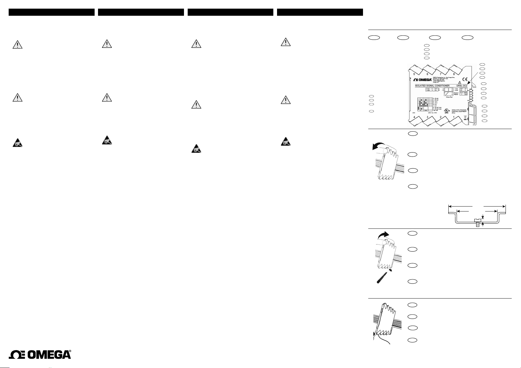
Sideskilt
DK
DIP-switchindstillinger
UK
DIP-switch settings
FR
Positions des
commutateurs
DE
DIP-Schaltereinstellungen
UK
Side label
FR
Etiquette
DK
Klemmenumre
UK
Terminal numbers
FR
Numéros des borniers
DE
Klemmennummer
DE
Typenschild
}
}
Montering på DIN-skinne
DK
For at forhindre kortslutning mellem power rail klemmerne på system DRSL modulet og skruerne til fastgørelse
af 7,5 mm DIN-skinnen, må skruehovederne højst være
3,5 mm høje.
Installation on DIN rail
UK
To avoid short circuit between the power rail connectors on
the DRSL devices and the screws holding the 7.5 mm DIN rail,
the head of the screws shall be no more than 3.5 mm high.
Montage sur rail DIN
FR
Pour éviter le court-circuit entre les connecteurs du rail
d’alimentation et les vis fixant le rail DIN 7,5 mm, l’hauteur des
têtes des vis ne doit dépasser 3,5 mm.
Montage auf DIN-Schiene
DE
Um Kurzschluss zwischen den Power Rail-Klemmen auf den
System DRSL-Geräten und den Schrauben zur Festhaltung der
7,5 mm DIN-Schiene zu vermeiden, muss die Köpfe der Schrauben höchst 3,5 mm Hoch sein.
Frigørelse fra DIN-skinne
DK
Husk først at demontere tilslutningsklemmerne med farlig
spænding. Modulet frigøres fra DIN-skinnen ved at løfte i
den nederste lås.
Demounting from DIN rail
UK
First, remember to demount the connectors with hazardous
voltages. Detach the device from the DIN rail by lifting the
bottom lock.
Démontage du rail DIN
FR
Tout d’abord, n’oubliez pas de démonter les connecteurs où
règnent des tensions dangereuses. Débloquez le verrou
inférieur pour dégager le module du rail DIN.
Lösen von DIN-Schiene
DE
Zunächst ist die gefährliche Spannung von den Anschlussklemmen zu trennen. Das Gerät wird von der DIN-Schiene
gelöst, indem man den unteren Verschluss löst.
Ledningskvadrat 0,13 x 2,5 mm2 flerkoret ledning.
DK
Klemskruetilspændingsmoment 0,5 Nm.
Wire size 0.13 x 2.5 mm
UK
Screw terminal torque 0.5 Nm.
Taille des fils 0,13 x 2,5 mm
FR
Pression max. avant déformation de la vis 0,5 Nm.
Leitungsquerschnitt 0,13 x 2,5 mm
DE
Klemmschraubenanzugsmoment 0,5 Nm.
35 mm
> 24 mm
2
stranded wire.
2
fils multibrins.
2
DK
Typenr.
}
UK
Type no.
FR
No. de type
DE
Typennr.
DK
Benforbindelser
Pin connections
UK
FR
Raccordement des
bornes
}
DE
Klemmenanschluss
DK
Godkendelser
UK
Approvals
FR
Homologations
}
DE
Zulassungen
< 3,5 mm
Litzendraht.
M5391-0514-DRSL-DC1
Page 2
DK UK FR DE
Rengøring
Modulet må, i spændingsløs tilstand, rengøres med en
klud let fugtet med destilleret vand.
Elektriske specifikationer
Specifikationsområde .......................... -25°C til +70°C
Specifikationsområde, DRSL-DC3
Lagringstemperatur
Forsyningsspænding, DC
Forsyningsspænding, DRSL-LPI &
DRSL-LPO
................................................ 2-trådsforsynet
Max. forbrug
............................................ ≤ 0.8 W
Max. forbrug, DRSL-DC2,
DRSL-SP2, DRSL-U
Isolationsspænding, test / arbejds- 2,5 kVAC/300 VAC
Dobbelt isolation
forsyning
Relativ luftfugtighed........................... < 95% RH (ikke kond.)
Mål (HxBxD)
Kapslingsklasse
Vægt
Forsyning af DRSL-PWR-RAIL Power rail
Power railen kan forsynes via DRSL-PCU Power Connector enhederne
eller alternativt via DRSL forsyningsklemmerne.
Følgende max. strømme er gældende ved forsyning af power railen:
DRSL modul
DRSL-PCU modul
Godkendelser
EMC 2004/108/EF ............................... EN 61326-1
LVD 2006/95/EF
UL, Standard for Safety
Sikker isolation....................................... EN 61140
................................... Indgang/udgang 1/udgang 2/
............................................ 113 x 6,1 x 115 mm
..................................... IP20
.......................................................... 70 g
............................................. 0,4 A (For-sikring 0,4 A)
................................... 2,5 A (For-sikring 2,5 A)
................................... EN 61010-1
... 0 til +70°C
............................. -40°C til +85°C
................... 16,8...31,2 VDC
.............................. ≤ 1,2 W
...................... UL 61010-1
User’s Guide
Cleaning
When disconnected, the device may be cleaned with a
cloth moistened with distilled water.
Electrical specifications
Specifications range ............................ -25°C to +70°C
Specifications range, DRSL-DC3
Storage temperature
Supply voltage, DC
Supply voltage, DRSL-LPI &
DRSL-LPO
................................................. Loop-powered
Max. consumption
Max. consump., DRSL-DC2,
DRSL-SP2, DRSL-U
Isolation voltage, test / working
Double isolation..................................... Input/output 1/output 2/supply
Relative humidity.................................. < 95% RH (non-cond.)
Dimensions (HxWxD)
Protection degree
Weight
....................................................... 70 g
Supply of the DRSL-PWR-RAIL Power rail
The Power rail can be powered via the DRSL-PCU Power Connector
units or alternatively via the DRSL power terminals.
Max. current values are to be observed:
DRSL unit
................................................. 0.4 A (protective fuse 0.4 A)
DRSL-PCU unit........................................ 2.5 A (protective fuse 2.5 A)
Approvals
EMC 2004/108/EC ............................... EN 61326-1
LVD 2006/95/EC
UL, Standard for Safety
Safe isolation
.......................................... EN 61140
..... 0 to +70°C
........................... -40°C to +85°C
............................... 16.8...31.2 VDC
................................. ≤ 0.8 W
.............................. ≤ 1.2 W
.... 2.5 kVAC/300 VAC
........................... 113 x 6.1 x 115 mm
................................. IP20
................................... EN 61010-1
...................... UL 61010-1
OMEGA ENGINEERING, INC. warrants this unit to be free of defects in materials and workmanship for a period of 13 months from date
of purchase. OMEGA’s WARRANTY adds an additional one (1) month grace period to the normal one (1) year product warranty to
cover handling and shipping time. This ensures that OMEGA’s customers receive maximum coverage on each product.
If the unit malfunctions, it must be returned to the factory for evaluation. OMEGA’s Customer Service Department will issue an
Authorized Return (AR) number immediately upon phone or written request. Upon examination by OMEGA, if the unit is found to be
defective, it will be repaired or replaced at no charge. OMEGA’s WARRANTY does not apply to defects resulting from any action of
the purchaser, including but not limited to mishandling, improper interfacing, operation outside of design limits, improper repair, or
unauthorized modification. This WARRANTY is VOID if the unit shows evidence of having been tampered with or shows evidence of
having been damaged as a result of excessive corrosion; or current, heat, moisture or vibration; improper specification; misapplication;
misuse or other operating conditions outside of OMEGA’s control. Components in which wear is not warranted, include but are not
limited to contact points, fuses, and triacs.
OMEGA is pleased to offer suggestions on the use of its various products. However, OMEGA neither assumes
responsibility for any omissions or errors nor assumes liability for any damages that result from the use of its products
in accordance with information provided by OMEGA, either verbal or written. OMEGA warrants only that the parts
manufactured by the company will be as specified and free of defects. OMEGA MAKES NO OTHER WARRANTIES OR
REPRESENTATIONS OF ANY KIND WHATSOEVER, EXPRESSED OR IMPLIED, EXCEPT THAT OF TITLE, AND ALL IMPLIED
WARRANTIES INCLUDING ANY WARRANTY OF MERCHANTABILITY AND FITNESS FOR A PARTICULAR PURPOSE ARE
HEREBY DISCLAIMED. LIMITATION OF LIABILITY: The remedies of purchaser set forth herein are exclusive, and the total
liability of OMEGA with respect to this order, whether based on contract, warranty, negligence, indemnification, strict
liability or otherwise, shall not exceed the purchase price of the component upon which liability is based. In no event
shall OMEGA be liable for consequential, incidental or special damages.
CONDITIONS: Equipment sold by OMEGA is not intended to be used, nor shall it be used: (1) as a “Basic Component” under 10 CFR 21
(NRC), used in or with any nuclear installation or activity; or (2) in medical applications or used on humans. Should any Product(s) be
used in or with any nuclear installation or activity, medical application, used on humans, or misused in any way, OMEGA assumes no
responsibility as set forth in our basic WARRANTY / DISCLAIMER language, and, additionally, purchaser will indemnify OMEGA and hold
OMEGA harmless from any liability or damage whatsoever arising out of the use of the Product(s) in such a manner.
Direct all warranty and repair requests/inquiries to the OMEGA Customer Service Department. BEFORE RETURNING ANY PRODUCT(S)
TO OMEGA, PURCHASER MUST OBTAIN AN AUTHORIZED RETURN (AR) NUMBER FROM OMEGA’S CUSTOMER SERVICE
DEPARTMENT (IN ORDER TO AVOID PROCESSING DELAYS). The assigned AR number should then be marked on the outside of the
return package and on any correspondence.
The purchaser is responsible for shipping charges, freight, insurance and proper packaging to prevent breakage in transit.
Shop online at
omega.com
e-mail: [email protected]
For latest product manuals:
www.omegamanual.info
®
FOR WARRANTY RETURNS, please have the following
information available BEFORE contacting OMEGA:
1. Purchase Order number under which the product was
PURCHASED,
2. Model and serial number of the product under warranty, and
3. Repair instructions and/or specific problems relative to the
product.
OMEGA’s policy is to make running changes, not model changes, whenever an improvement is possible. This affords our customers the
latest in technology and engineering. OMEGA is a registered trademark of OMEGA ENGINEERING, INC.
© Copyright 2014 OMEGA ENGINEERING, INC. All rights reserved. This document may not be copied, photocopied, reproduced,
translated, or reduced to any electronic medium or machine-readable form, in whole or in part, without the prior written consent of
OMEGA ENGINEERING, INC.
Maintenance et entretien
Une fois le module hors tension, prenez un chion imbibé
d’eau distillée pour le nettoyer.
Spécifications
Plage d’utilisation ................................. -25°C à +70°C
Plage d’utilisation, DRSL-DC3
Température de stockage
Tension d’alimentation, cc
Tension d’alimentation, DRSL-LPI &
DRSL-LPO
................................................ Auto-alimenté
Consommation
Consommation, DRSL-DC2,
DRSL-SP2, DRSL-U .
Tension d’isolation, test / service
Isolation double
Humidité relative
Dimensions, (HxLxP)
Degré de protection
Poids........................................................... 70 g
Alimentation du Rail DRSL-PWR-RAIL
Le rail d’alimentation peut être alimenté par les contrôleurs type DRSLPCU. Pour la série DRSL il est possible en alimentant seulement un
module sur sa borne d’alimentation.
Valeurs maxi de courant observées :
Module DRSL........................................... 0,4 A (fusible 0,4 A)
Module DRSL-PCU
Approbations
EMC 2004/108/CE ............................... EN 61326-1
LVD 2006/95/CE
UL, Standard for Safety
Isolation sûre
.......................................... EN 61140
.......... 0 à +70°C
.................. -40°C à +85°C
................. 16,8...31,2 Vcc
........................................ ≤ 0,8 W
............................. ≤ 1,2 W
..................................... Entrée/sortie 1/sortie 2/aliment.
.................................. < 95% HR (sans cond.)
................................... EN 61010-1
.. 2,5 kVca/300 Vca
........................... 113 x 6,1 x 115 mm
............................. IP20
................................. 2,5 A (fusible 2,5 A)
...................... UL 61010-1
WARRANTY/DISCLAIMER
RETURN REQUESTS / INQUIRIES
FOR NON-WARRANTY REPAIRS,
charges. Have the following information available BEFORE contacting
OMEGA:
1. Purchase Order number to cover the COST of the repair,
2. Model and serial number of the product, and
3. Repair instructions and/or specific problems relative to the product.
Reinigung
Das Gerät darf in spannungslosem Zustand mit einem Lappen gereinigt werden, der mit destilliertem Wasser leicht
angefeuchtet ist.
Elektrische Daten
Umgebungstemperatur ...................... -25°C bis +70°C
Umgebungstemperatur, DRSL-DC3
Lagertemperatur
Versorgungsspannung, DC
Versorgungsspann., DRSL-LPI &
DRSL-LPO
Stromverbrauch
Stromverbr., DRSL-DC2,
DRSL-SP2, DRSL-U .
Isolationsspannung, Test / Arbeits- 2,5 kVAC/300 VAC
Doppelte Isolierung ............................. Eing./Ausg.1/Ausg. 2/Versorg.
Relative Luftfeuchtigkeit
Abmessungen (HxBxT)
Schutzart
Gewicht
Versorgung der Power Rail DRSL-PWR-RAIL
Die Power Rail kann mit den Einspeisebausteinen DRSL-PCU versorgt
werden oder alternativ über die Versorgungsklemmen
(7 und 8) der DRSL Geräte.
Zu beachten sind die folgenden maximalen Stromwerte:
DRSL Geräte:
Einspeisebaustein DRSL-PCU
Zulassungen
EMC 2004/108/EG ............................... EN 61326-1
LVD 2006/95/EG
UL, Standard for Safety
Sichere Trennung
................................... -40°C bis +85°C
................................................. 2-Draht-Versorgung
....................................... ≤ 0,8 W
.................................................. IP20
..................................................... 70 g
........................................... 0,4 A (Schutzsicherung 0,4 A)
................................... EN 61010-1
.................................. EN 61140
0 bis +70°C
................ 16,8...31,2 VDC
............................. ≤ 1,2 W
.................. < 95% RF (nicht kond.)
...................... 113 x 6,1 x 115 mm
.......... 2,5 A (Schutzsicherung 2,5 A)
...................... UL 61010-1
consult OMEGA for current repair
INSTALLATION GUIDE FOR DRSL-DC1, DRSL-DC2, DRSL-DC3, DRSL-DC4,
DRSL-SP1, DRSL-SP2, DRSL-SP3, DRSL-U, DRSL-LPI, and DRSL-LPO, DIN
RAIL SIGNAL CONDITIONERS and DRSL-PCU POWER CONNECTION UNIT
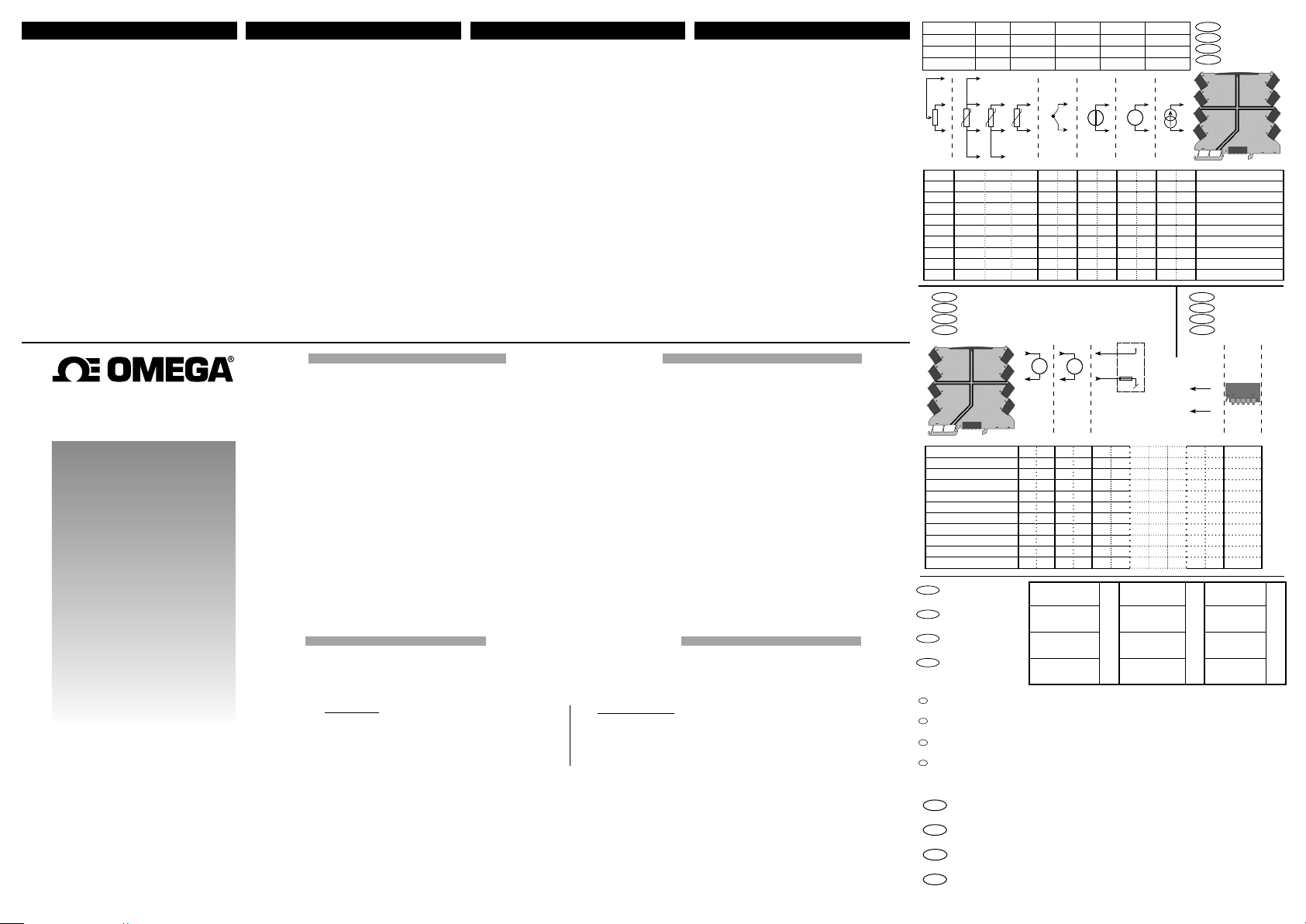
DK
Potentiometer RT D TC Spænding Tx Strøm
Potentiometer RT D TC Voltage Tx Current
Potentiomètre RT D TC Tension Tx Courant
Potentiometer WTH TE Spannung Tx Strom
Indgangssignaler
UK
Input signals
FR
Signaux d’entrée
DE
4
+
++ +
Tx
-
- --
3
2
1
++++ -- - -
3 4 3 4 4 3 DRSL-DC2
3 4 4 3 DRSL-DC3
2,3 & 4 1,2 & 3,4 1,2 & 3 2 & 3 1 2 4 2 4 3 3 2 DRSL-U
DK
Udgangssignaler
UK
Output signals
FR
Signaux de sortie
DE
Ausgangssignale
5
mA
6
7
3 4 3 4 4 3 DRSL-SP2
3 4 4 3 DRSL-DC4
3 4 4 3 DRSL-SP3
+
-
+
+
V
4...20 mA
-
-
8
++ - -
DRSL-DC1 5 6 - - 7 8 Y
DRSL-DC2 5 6 5 6 7 8 Y
DRSL-DC3 5 6 5 6 7 8 Y
DRSL-SP1 (1 / 2 ch.) 5 / 2 6 / 1 - - 7 8 Y
DRSL-SP2 (1 / 2 ch.) 5 / 2 6 / 1 5 / 2 6 / 1 7 8 Y
DRSL-U 5 6 5 6 7 8 Y
DRSL-DC4 5 6 5 6 7 8 Y
DRSL-SP3 (1 / 2 ch.) 5 / 2 6 / 1 5 / 2 6 / 1 7 8 Y
DRSL-LPI (1 / 2 ch.) 5 / 7 6 / 8 - - - - N
DRSL-LPO (1 / 2 ch.) - - - - 5 / 7 6 / 8 - - N
DRSL-PCU - - - - 7 8 Y
DK
Påkrævet ekstern sikring
UK
Required external fuse
FR
Fusible externe requise
Erforderliche externe
DE
Sicherung
DK
Sikringsegenskaber:
2,5 A sikringen skal afbryde efter højst 120 sekunder ved 6,4 A.
UK
Fuse characteristics:
The 2.5 A fuse must break after not more than 120 seconds at 6.4 A.
FR
Spécifications du fusible :
Le fusible de 2,5 A doit fondre après pas plus de 120 secondes à 6,4 A.
DE
Sicherungseigenschaften:
Die 2,5 A Sicherung muss nach nicht mehr als 120 Sekunden bei 6,4 A abbrechen.
Dokumentation, godkendelser og yderligere information findes på internettet på
DK
www.omega.dk
Documentation, permits and other information can be found on the internet at
UK
www.omega.com
La documentation et toute autre information peuvent être trouvées sur l’Internet sur
FR
notre site: www.ome ga .fr
Dokumentationen, Zulassungen und andere Informationen können auf unserer
DE
Internet-Seite unter www.omega.de gefunden und abgerufen werden.
Forsyning direkte
på modulet
Supply directly
on device
Alimentation directe-
ment sur le module
Versorgung direkt
am Gerät
+ -
2.5 A
4 3 DRSL-DC1
4 3 DRSL-SP1
4 / 2 3 / 1 DRSL-LPI (1 / 2 ch.)
4 / 2 3 / 1 DRSL-LPO (1 / 2 ch.)
DK
Forsyning
UK
Supply
FR
Alimentation
DE
+ Vsupply
Versorgung
+
24 VDC
-
+ -
Forsyning af
power rail via
standardmodul
Supply of power rail
using a
standard device
Alimentation du rail
d’alimentation avec
module standard
Versorgung von
Power Rail mit
Standardgerät
0.4 A
DRSL-PCU Power
connect unit
DRSL-PCU Power
connect unit
DRSL-PCU Power
connect unit
DRSL-PCU Power
Connect Unit
Eingangssignale
Type
Power
rail
2,5 A
 Loading...