

Page 1
e-mail: [email protected]
For latest product manuals:
omegamanual.info
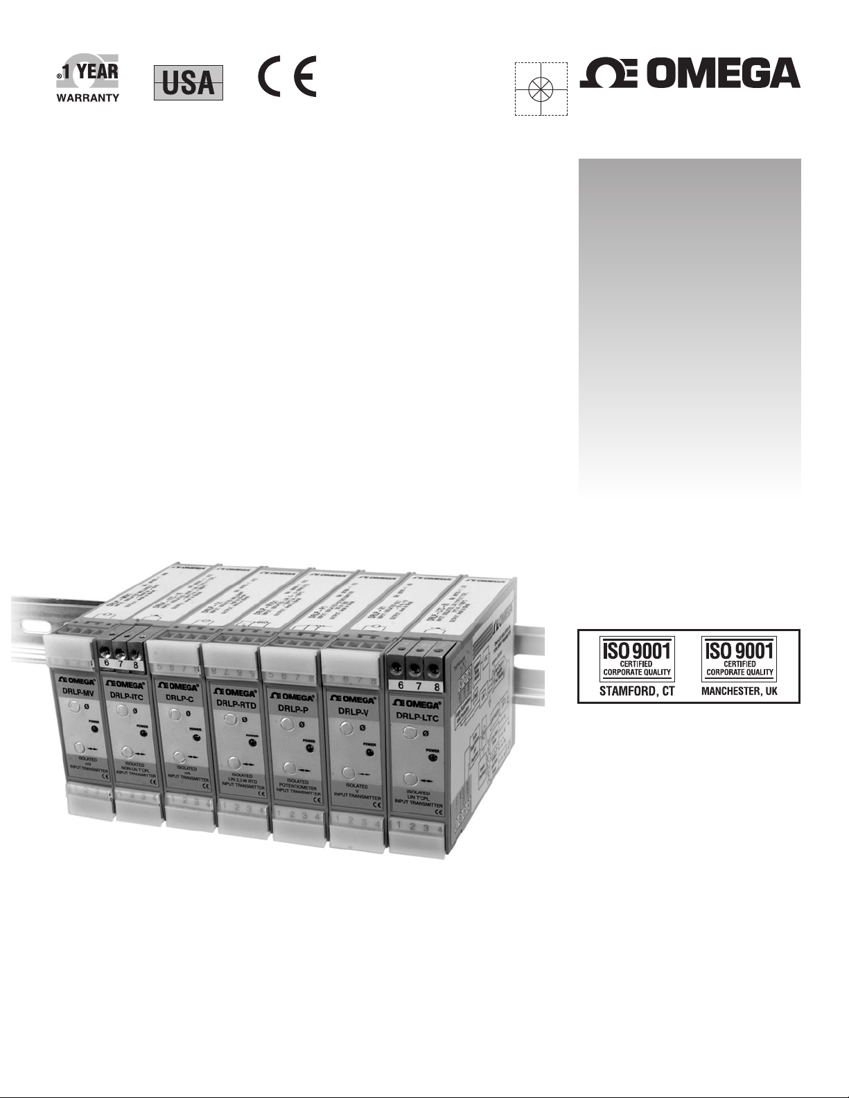
DRLP SERIES
Isolated DIN Rail Mount
2-Wire Trasmitters
MADE IN
Shop online at
omega.com
User’s Guide
®
®
Page 2

Servicing North America:
U.S.A.: Omega Engineering, Inc., One Omega Drive, P.O. Box 4047
ISO 9001 Certified Stamford, CT 06907-0047 USA
Canada: 976 Bergar
Laval (Quebec), H7L 5A1 Canada
Toll-Free: 1-800-826-6342 TEL: (514) 856-6928
FAX: (514) 856-6886 e-mail: [email protected]
For immediate technical or application assistance:
U.S.A. and Canada: Sales Service: 1-800-826-6342/1-800-TC-OMEGA
®
Customer Service: 1-800-622-2378/1-800-622-BEST
®
Engineering Service: 1-800-872-9436/1-800-USA-WHEN
®
Mexico/ En Español: 001 (203) 359-7803 FAX: 001 (203) 359-7807
Latin America: [email protected] e-mail: [email protected]
º
Benelux: Managed by the United Kingdom Office
Czech Republic: Frystatska 184
733 01 Karviná, Czech Republic
Toll-Free: 0800-1-66342 TEL: +420-59-6311899
FAX: +420-59-6311114 e-mail: [email protected]
France: Managed by the United Kingdom Office
Toll-Free: 0800 466 342 TEL: +33 (0) 161 37 29 00
FAX: +33 (0) 130 57 54 27 e-mail: [email protected]
Germany/ Austria: Daimlerstrasse 26
D-75392 Deckenpfronn, Germany
Toll-Free: 0800 6397678 TEL: +49 (0) 7056 9398-0
FAX: +49 (0) 7056 9398-29 e-mail: [email protected]
United Kingdom: OMEGA Engineering Ltd.
ISO 9001 Certified
One Omega Drive, River Bend Technology Centre, Northbank
Irlam, Manchester M44 5BD United Kingdom
Toll-Free: 0800-488-488 TEL: +44 (0) 161 777-6611
FAX: +44 (0) 161 777-6622 e-mail: [email protected]
OMEGAnet®Online Service Internet e-mail
omega.com [email protected]
It is the policy of OMEGA Engineering, Inc. to comply with all worldwide safety and EMC/EMI
regulations that apply. OMEGA is constantly pursuing certification of its products to the European New
Approach Directives. OMEGA will add the CE mark to every appropriate device upon certification.
The information contained in this document is believed to be correct, but OMEGA accepts no liability for any
errors it contains, and reserves the right to alter specifications without notice.
WARNING: These products are not designed for use in, and should not be used for, human applications.
®
WARRANTY/DISCLAIMER
OMEGA ENGINEERING, INC. warrants this unit to be free of defects in materials and workmanship for a
period of 13 months from date of purchase. OMEGA’s WARRANTY adds an additional one (1) month
grace period to the normal one (1) year product warranty to cover handling and shipping time. This
ensures that OMEGA’s customers receive maximum coverage on each product.
If the unit malfunctions, it must be returned to the factory for evaluation. OMEGA’s Customer Service
Department will issue an Authorized Return (AR) number immediately upon phone or written request.
Upon examination by OMEGA, if the unit is found to be defective, it will be repaired or replaced at no
charge. OMEGA’s WARRANTY does not apply to defects resulting from any action of the purchaser,
including but not limited to mishandling, improper interfacing, operation outside of design limits,
improper repair, or unauthorized modification. This WARRANTY is VOID if the unit shows evidence of
having been tampered with or shows evidence of having been damaged as a result of excessive corrosion;
or current, heat, moisture or vibration; improper specification; misapplication; misuse or other operating
conditions outside of OMEGA’s control. Components in which wear is not warranted, include but are not
limited to contact points, fuses, and triacs.
OMEGA is pleased to offer suggestions on the use of its various products. However,
OMEGA neither assumes responsibility for any omissions or errors nor assumes liability for any
damages that result from the use of its products in accordance with information provided by
OMEGA, either verbal or written. OMEGA warrants only that the parts manufactured by the
company will be as specified and free of defects. OMEGA MAKES NO OTHER WARRANTIES OR
REPRESENTATIONS OF ANY KIND WHATSOEVER, EXPRESSED OR IMPLIED, EXCEPT THAT OF
TITLE, AND ALL IMPLIED WARRANTIES INCLUDING ANY WARRANTY OF MERCHANTABILITY
AND FITNESS FOR A PARTICULAR PURPOSE ARE HEREBY DISCLAIMED. LIMITATION OF
LIABILITY: The remedies of purchaser set forth herein are exclusive, and the total liability of
OMEGA with respect to this order, whether based on contract, warranty, negligence,
indemnification, strict liability or otherwise, shall not exceed the purchase price of the
co mponent upon whi c h liab ility is based. In no event shall OMEGA be liable for
consequential, incidental or special damages.
CONDITIONS: Equipment sold by OMEGA is not intended to be used, nor shall it be used: (1) as a “Basic
Component” under 10 CFR 21 (NRC), used in or with any nuclear installation or activity; or (2) in medical
applications or used on humans. Should any Product(s) be used in or with any nuclear installation or
activity, medical application, used on humans, or misused in any way, OMEGA assumes no responsibility
as set forth in our basic WARRANTY/DISCLAIMER language, and, additionally, purchaser will indemnify
OMEGA and hold OMEGA harmless from any liability or damage whatsoever arising out of the use of the
Product(s) in such a manner.
RETURN REQUESTS/INQUIRIES
Direct all warranty and repair requests/inquiries to the OMEGA Customer Service Department. BEFORE
RETURNING ANY PRODUCT(S) TO OMEGA, PURCHASER MUST OBTAIN AN AUTHORIZED RETURN
(AR) N UMBE R FRO M OME G A’S CUS T OME R SERVIC E DEPA RT M ENT ( IN OR D ER T O AVOI D
PROCESSING DELAYS). The assigned AR number should then be marked on the outside of the return
package and on any correspondence.
The purchaser is responsible for shipping charges, freight, insurance and proper packaging to prevent
breakage in transit.
FOR WARRANTY
RETURNS, please have the
following information available BEFORE
contacting OMEGA:
1. Purchase Order number under which the product
was PURCHASED,
2. Model and serial number of the product under
warranty, and
3. Repair instructions and/or specific problems
relative to the product.
FOR NON-WARRANTY REPAIRS,
consult OMEGA
for current repair charges. Have the following
information available BEFORE contacting OMEGA:
1. Purchase Order number to cover the COST
of the repair,
2. Model and serial number of the product, and
3. Repair instructions and/or specific problems
relative to the product.
OMEGA’s policy is to make running changes, not model changes, whenever an improvement is possible. This affords
our customers the latest in technology and engineering.
OMEGA is a registered trademark of OMEGA ENGINEERING, INC.
© Copyright 2012 OMEGA ENGINEERING, INC. All rights reserved. This document may not be copied, photocopied,
reproduced, translated, or reduced to any electronic medium or machine-readable form, in whole or in part, without the
prior written consent of OMEGA ENGINEERING, INC.
Page 3

DRLP Series
Isolated DIN Rail Mount 2-Wire Transmitters
Features
±0.03% Accuracy (Typical)
•
±0.01% Linearity
•
1500Vrms Transformer Isolation & 240Vrms Field-side
•
Protection
ANSI/IEEE C37.90.1 Transient Protection
•
Wide Loop Supply Voltage, 10.8V to 60V
•
5-Pole Low-Pass Filtering
•
Up to 160dB CMR
•
85dB NMR at 60Hz, 80dB at 50Hz
•
Protected Against Reverse Connection of Loop Voltage
•
–40°C to +80°C Operating Temperature
•
Mounts on DIN Rail EN 50022, 35x7.5 or 35x15
•
CSA C/US Certied
•
(Class I, Division 2, Groups A, B, C, D)
CE Compliant
•
Manufactured per RoHS Directive 2002/95/EC
•
Instrument Class® Performance
“Best of Breed” accuracy, linearity, stability and noise specications.
Outstanding protection and isolation performance for Input, Output and
Power connections. Capable of operating on the widest of loop supply
power and over the broadest operating temperature range!
Description
Omega’s new DRLP series of loop powered 2-wire transmitters consists
of seven family groups with a total of 48 transmitter models that interface
to a wide variety of voltage, current, temperature and position measuring
devices. The DRLP is the latest introduction of products available from
Omega, which provide superior specications such as ±0.03% accuracy,
ve poles of ltering, 1500Vrms continuous isolation, low output noise,
and much more.
The DRLP 2-wire transmitter conditions and sends analog signals from
sensors located in the “eld” to monitoring and control equipment,
usually computers, located thousands of feet away in central control
areas. The DRLP accepts a wide range of inputs, including millivolt, volt,
milliamp, thermocouple, RTD, potentiometer, and slide wire. It operates
on power from a 2-wire signal loop and modulates the supply current to
represent the input signal within a 4 to 20-milliamp range.
Two-wire transmission loops are very economical methods for connecting sensors to distant control rooms. Since the DRLP operates from
the signal loop current, no additional, expensive power and wiring are
required. Only low cost, twisted pair wiring is needed.
4
4
Page 4

ANALOG VOLTAGE INPUT TRANSMITTERS
MODEL INPUT RANGE MODEL INPUT RANGE
DRLP-MV1 ±10mV DRLP31-01 ±1V
DRLP-MV2 ±50mV DRLP31-02 ±5V
DRLP-MV3 ±100mV DRLP31-03 ±10V
DRLP-MV4 0 - 10mV DRLP31-04 0 - 1V
DRLP-MV5 0 - 50mV DRLP31-05 0 - 5V
DRLP-MV6 0 - 100mV DRLP31-06 0 - 10V
DRLP31-07 ±20V
DRLP31-08 0 - 20V
ANALOG CURRENT INPUT TRANSMITTERS
MODEL INPUT RANGE
DRLP-C1 4 to 20mA
DRLP-C2 0 to 20mA
LINEARIZED 2- OR 3-WIRE RTD INPUT TRANSMITTERS
MODEL TYPE** INPUT RANGE
DRLP-RTD1 100ΩPt –100°C to +100°C (–148°F to +212°F)
DRLP-RTD2 100ΩPt 0°C to +100°C (+32°F to +212°F)
DRLP-RTD3 100ΩPt 0°C to +200°C (+32°F to +392°F)
DRLP-RTD4 100ΩPt 0°C to +600°C (+32°F to +1112°F)
DRLP-RTD5 100ΩPt 0°C to +400°C (+32°F to +752°F)
DRLP-RTD6 120ΩNi 0°C to +300°C (+32°F to +572°F)
POTENTIOMETER INPUT TRANSMITTERS
MODEL INPUT RANGE
DRLP-P1 0 to 100Ω
DRLP-P2 0 to 500Ω
DRLP-P3 0 to 1kΩ
DRLP-P4 0 to 10kΩ
THERMOCOUPLE INPUT TRANSMITTERS
MODEL TYPE
‡
INPUT RANGE
DRLP-ITC-J J –100°C to +760°C (–148°F to +1400°F)
DRLP-ITC-K K –100°C to +1350°C (–148°F to +2462°F)
DRLP-ITC-T T –100°C to +400°C (–148°F to +752°F)
DRLP-ITC-E E 0°C to +900°C (+32°F to +1652°F)
DRLP-ITC-R R 0°C to +1750°C (+32°F to +3182°F)
DRLP-ITC-S S 0°C to +1750°C (+32°F to +3182°F)
DRLP-ITC-B B 0°C to +1800°C (+32°F to +3272°F)
DRLP-ITC-N N –100°C to +1300°C (–148°F to +2372°F)
LINEARIZED THERMOCOUPLE INPUT TRANSMITTERS
MODEL TYPE
‡
INPUT RANGE
DRLP-LTC-J1 J 0°C to +760°C (+32°F to +1400°F)
DRLP-LTC-J2 J –100°C to +300°C (–148°F to +572°F)
DRLP-LTC-J3 J 0°C to +500°C (+32°F to +932°F)
DRLP-LTC-K1 K 0°C to +1000°C (+32°F to +1832°F)
DRLP-LTC-K2 K 0°C to +500°C (+32°F to +932°F)
DRLP-LTC-K3 K –100°C to +1350°C (–148°F to +2462°F)
DRLP-LTC-K4 K 0°C to +1200°C (+32°F to +2192°F)
DRLP-LTC-T1 T –100°C to +400°C (–148°F to +752°F)
DRLP-LTC-T2 T 0°C to +200°C (+32°F to +392°F)
DRLP-LTC-E E 0°C to +1000°C (+32°F to +1832°F)
DRLP-LTC-R R +500°C to +1750°C (+932°F to +3182°F)
DRLP-LTC-S S +500°C to +1750°C (+932°F to +3182°F)
DRLP-LTC-B B +500°C to +1800°C (+932°F to +3272°F)
DRLP-LTC-N N –100°C to +1300°C (–148°F to +2372°F)
‡
THERMOCOUPLE ALLOY COMBINATIONS
Standards: DIN IEC 584, ANSI MC96-1-82, JIS C 1602-1981
TYPE MATERIAL
J Iron vs. Copper-Nickel
K Nickel-Chromium vs. Nickel-Aluminum
T Copper vs. Copper-Nickel
E Nickel-Chromium vs. Copper-Nickel
R Platinum-13% Rhodium vs. Platinum
S Platinum-10% Rhodium vs. Platinum
B Platinum-30% Rhodium vs.Platinum-6%Rhodium
N Nickel-14.2% Chromium-1.4% Silicon vs. Nickel-4.4%
Silicon-0.1% Magnesium
**RTD STANDARDS
TYPE ALPHA COEFFICIENT DIN JIS
100Ω Pt 0.00385 DIN 43760 JIS C 1604-1989
120Ω Ni 0.00672
DRLP Selection Guide
5
Page 5
DRLP-MV/DRLP-V
Analog Voltage Input Transmitters
Accepts Millivolt and Voltage Level Signals
•
Process Current Output
•
1500Vrms Transformer Isolation
•
ANSI/IEEE C37.90.1 Transient Protection
•
Input and Output Protected to 240VAC Continuous
•
Up to 60V Loop Voltage
•
160dB CMR
•
85dB NMR at 60Hz, 80dB at 50Hz
•
±0.03% Accuracy
•
±0.01% Linearity
•
Easily Mounts on Standard DIN Rail
•
CSA C/US Certied
•
CE Compliant
•
DescriptionFeatures
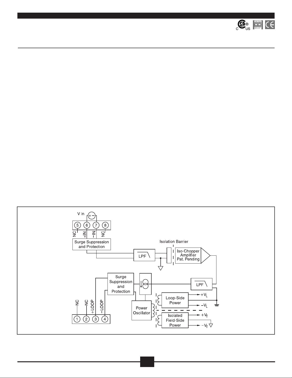
Each DRLP-MV and DRLP-V voltage input transmitter provides a single
channel of analog input which is ltered, isolated, amplied, and converted to a process current output (Figure 1). Signal ltering is accomplished
with a ve-pole lter, which provides 85dB of normal-mode rejection
at 60Hz and 80dB at 50Hz. An anti-aliasing pole is located on the eld
side of the isolation barrier, and the other four are on the process loop
side. After the initial eld-side ltering, the input signal is chopped by a
proprietary chopper circuit. Isolation is provided by transformer coupling,
again using a proprietary technique to suppress transmission of common
mode spikes or surges.
Special input and output circuits on the DRLP-MV and DRLP-V transmitters provide protection against accidental connection of power-line
voltages up to 240VAC and against transient events as dened by ANSI/
IEEE C37.90.1. Signal and loop power lines are secured to the module
using screw terminals, which are in pluggable terminal blocks for ease of
system assembly and reconguration.
The modules have excellent stability over time and do not require recalibration, however, zero and span settings are adjustable up to ±10% to
accommodate situations where ne-tuning is desired. The adjustments
are made using potentiometers located under the front panel label and
are non-interactive for ease of use.
Figure 1: DRLP-MV/DRLP-V Block Diagram
6
6
Page 6
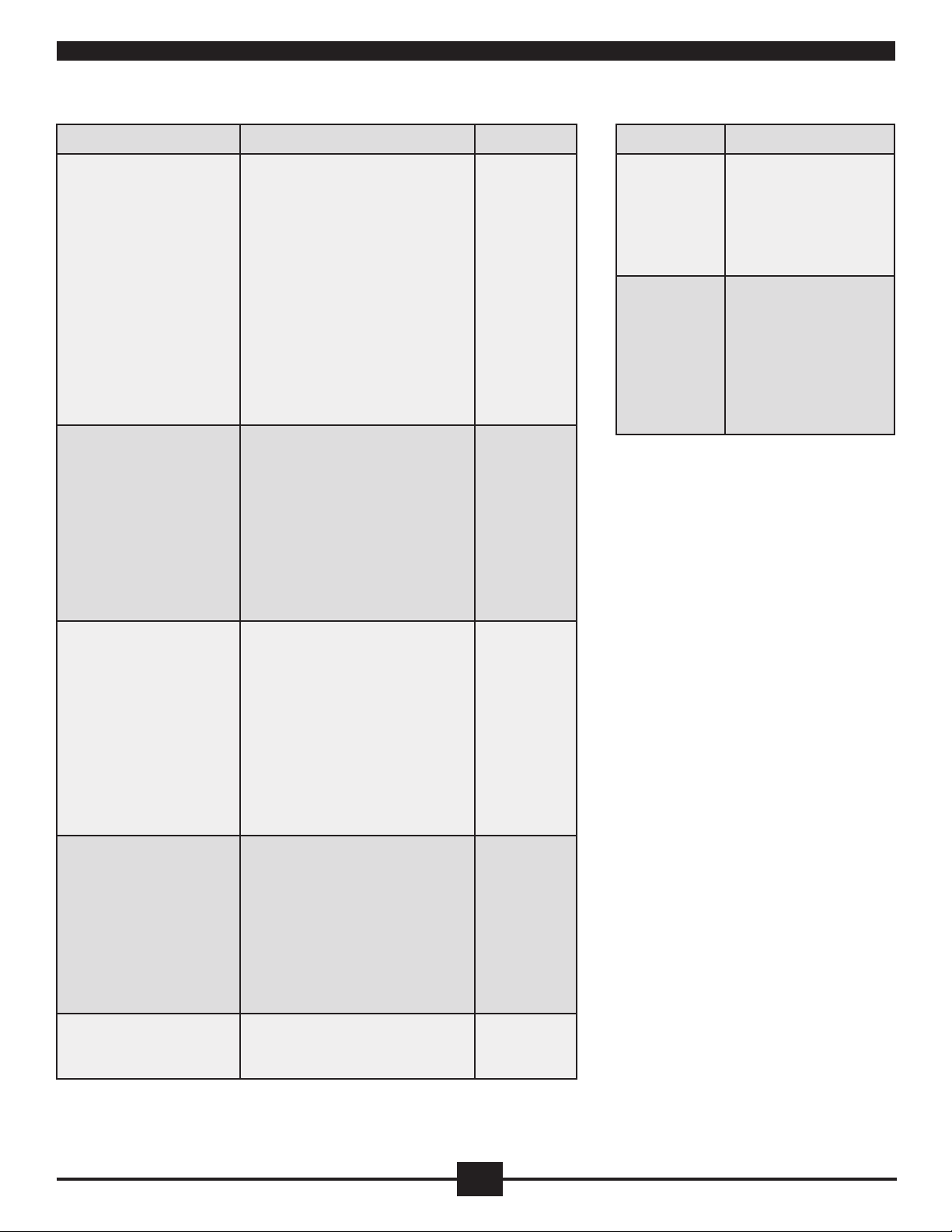
Specifications Typical at T
=+25°C and +24V loop voltage
A
Ordering Information
Module DRLP-MV DRLP-V
Input Range
Input Bias Current
Input Resistance
Normal
Power Off
Overload
Input Protection
Continuous
Transient
CMV, Input to Output
Continuous
Transient
CMR (50Hz or 60Hz)
NMR
Adjustability
Accuracy
Conformity
Stability
Offset
Gain
Noise
Output, 100kHz
Bandwidth, –3dB
Response Time, 90% Span
(1)
±10mV to ±100mV
±0.5nA
50MW
66kW
66kW
240Vrms max
ANSI/IEEE C37.90.1
1500Vrms max
ANSI/IEEE C37.90.1
160dB
85dB at 60Hz, 80dB at 50Hz
±10% Zero and Span
±0.03%
±0.01%
±20ppm/°C
±80ppm/°C
3µArms
3Hz
165ms
±1V to ±20V
±0.05nA
2MW
2MW
2MW
*
*
*
*
*
*
*
*
*
*
*
*
*
*
Module Input Range
DRLP-MV1
DRLP-MV2
DRLP-MV3
DRLP-MV4
DRLP-MV5
DRLP-MV6
DRLP-V1
DRLP-V2
DRLP-V3
DRLP-V4
DRLP-V5
DRLP-V6
DRLP-V7
DRLP-V8
–10mV to +10mV
–50mV to +50mV
–100mV to +100mV
0mV to +10mV
0mV to +50mV
0mV to +100mV
–1V to +1V
–5V to +5V
–10V to +10V
0V to +1V
0V to +5V
0V to +10V
–20V to +20V
0V to +20V
Output Range
Output Limits
Under-range
Over-range
Output Protection
Reverse Polarity
Over-voltage
Transient
Loop Supply Voltage
Loop Supply Sensitivity
Turn-On Delay
Environmental
Operating Temp. Range
Storage Temp. Range
Relative Humidity
Emissions EN61000-6-4
Radiated, Conducted
Immunity EN61000-6-2
RF
ESD, EFT
Mechanical Dimensions
(h)(w)(d)
Mounting
4mA to 20mA
2.8mA
29mA
Continuous
240Vrms continuous
ANSI/IEEE C37.90.1
10.8V to 60V
±0.0005%/V
400ms
–40°C to +80°C
–40°C to +80°C
0 to 95% Noncondensing
ISM, Group 1
Class A
ISM, Group 1
Performance A ±0.5% Span Error
Performance B
2.95” x 0.89” x 4.13”
(75mm x 22.5mm x 105mm)
DIN EN 50022 –35x7.5 or –35x15 rail
*
*
*
*
*
*
*
*
*
*
*
*
*
*
*
NOTES:
* Same specication as DRLP-MV. (1) Includes linearity, hysteresis and repeatability.
777
Page 7
Analog Current Input Transmitters
Accepts Milliamp Level Signals
•
Process Current Output
•
1500Vrms Transformer Isolation
•
ANSI/IEEE C37.90.1 Transient Protection
•
Input and Output Protected to 240VAC Continuous
•
Up to 60V Loop Voltage
•
105dB CMR
•
±0.03% Accuracy
•
±0.01% Linearity
•
Easily Mounts on Standard DIN Rail
•
CSA C/US Certied
•
CE Compliant
•
DRLP-C
DescriptionFeatures
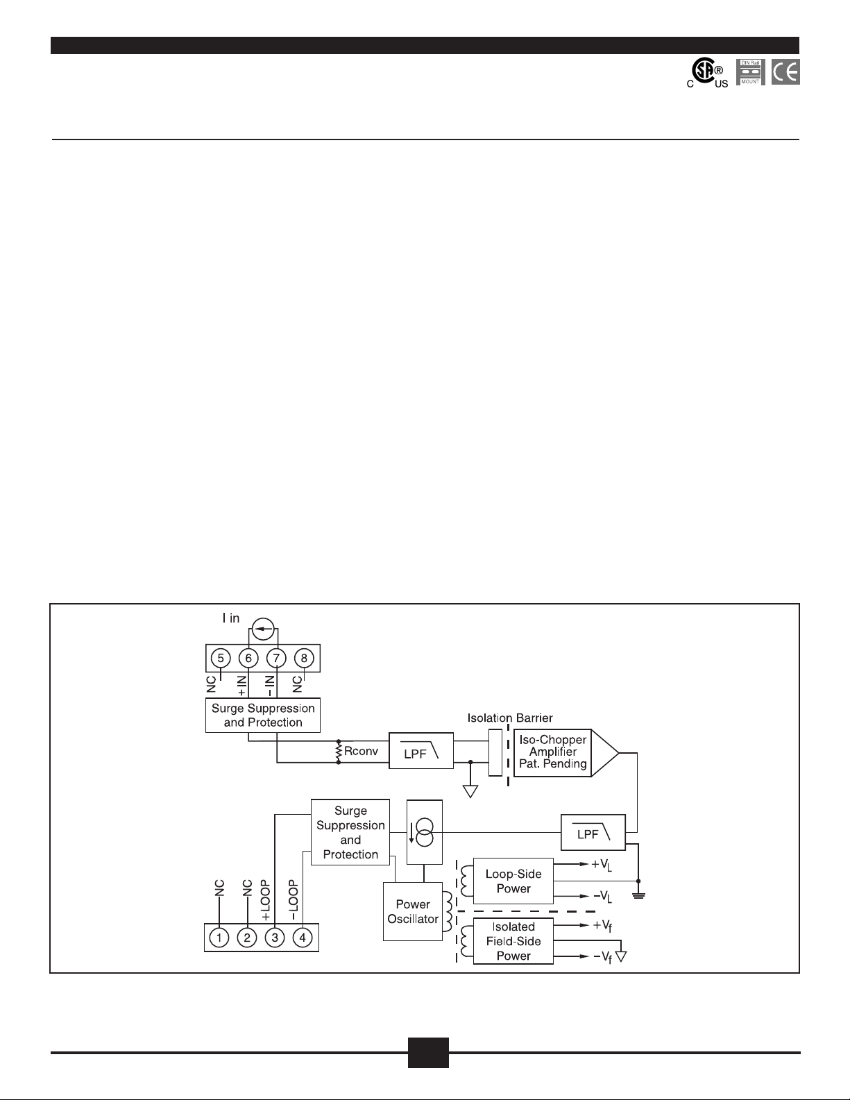
Each DRLP-C current input transmitter provides a single channel of ana-
log input which is ltered, isolated, amplied, and converted to a process
current output (Figure 1). Signal ltering is accomplished with a ve-pole
lter, which provides 80dB per decade of normal-mode rejection above
100Hz. An anti-aliasing pole is located on the eld side of the isolation
barrier, and the other four are on the process loop side. After the initial
eld-side ltering, the input signal is chopped by a proprietary chopper circuit. Isolation is provided by transformer coupling, again using a
proprietary technique to suppress transmission of common mode spikes
or surges.
Special input and output circuits on the DRLP-C transmitters provide
protection against accidental connection of power-line voltages up
to 240VAC and against transient events as dened by ANSI/IEEE
C37.90.1. Signal and loop power lines are secured to the module using
screw terminals, which are in pluggable terminal blocks for ease of
system assembly and reconguration.
The modules have excellent stability over time and do not require recalibration, however, zero and span settings are adjustable up to ±10% to
accommodate situations where ne-tuning is desired. The adjustments
are made using potentiometers located under the front panel label and
are non-interactive for ease of use.
Figure 1: DRLP-C Block Diagram
8
8
Page 8
Specifications Typical at T
=+25°C and +24V loop voltage
A
Ordering Information
Module DRLP-C
Input Range
Current Conversion Resistor
Input Protection
Continuous
Transient
CMV, Input to Output
Continuous
Transient
CMR (50Hz or 60Hz)
NMR (–3dB at 100Hz)
Adjustability
Accuracy
Conformity
Stability
Offset
Gain
Noise
Output, 100kHz
Bandwidth, –3dB
Response Time, 90% Span
Output Range
Output Limits
Under-range
Over-range
Output Protection
Reverse Polarity
Over-voltage
Transient
Loop Supply Voltage
Loop Supply Sensitivity
Turn-On Delay
(1)
0-20mA or 4-20mA
50.00W
240Vrms max
ANSI/IEEE C37.90.1
1500Vrms max
ANSI/IEEE C37.90.1
105dB
80dB/decade Above 100Hz
±10% Zero and Span
±0.03%
±0.01%
±30ppm/°C
±90ppm/°C
3µArms
100Hz
5ms
4mA to 20mA
2.8mA
29mA
Continuous
240Vrms Continuous
ANSI/IEEE C37.90.1
10.8V to 60V
±0.0005%/V
400ms
Module Input Range
DRLP-C1
DRLP-C2
4-20mA
0-20mA
Environmental
Operating Temp. Range
Storage Temp. Range
Relative Humidity
Emissions EN61000-6-4
Radiated, Conducted
Immunity EN61000-6-2
RF
ESD, EFT
Mechanical Dimensions
(h)(w)(d)
Mounting
–40°C to +80°C
–40°C to +80°C
0 to 95% Noncondensing
ISM, Group 1
Class A
ISM, Group 1
Performance A ±0.5% Span Error
Performance B
2.95” x 0.89” x 4.13”
(75mm x 22.5mm x 105mm)
DIN EN 50022 –35x7.5 or –35x15 rail
9
Page 9
DRLP-RTD
Linearized 2- or 3-Wire RTD Input Transmitters
Features
Interfaces to 100W Platinum or 120W Nickel RTDs
•
Linearizes RTD Signal
•
Process Current Output
•
1500Vrms Transformer Isolation
•
ANSI/IEEE C37.90.1 Transient Protection
•
Input and Output Protected to 240VAC Continuous
•
Up to 60V Loop Voltage
•
160dB CMR
•
85dB NMR at 60Hz, 80dB at 50Hz
•
±0.1% Accuracy
•
±0.025% Conformity
•
Easily Mounts on Standard DIN Rail
•
CSA C/US Certied
•
CE Compliant
•
Description
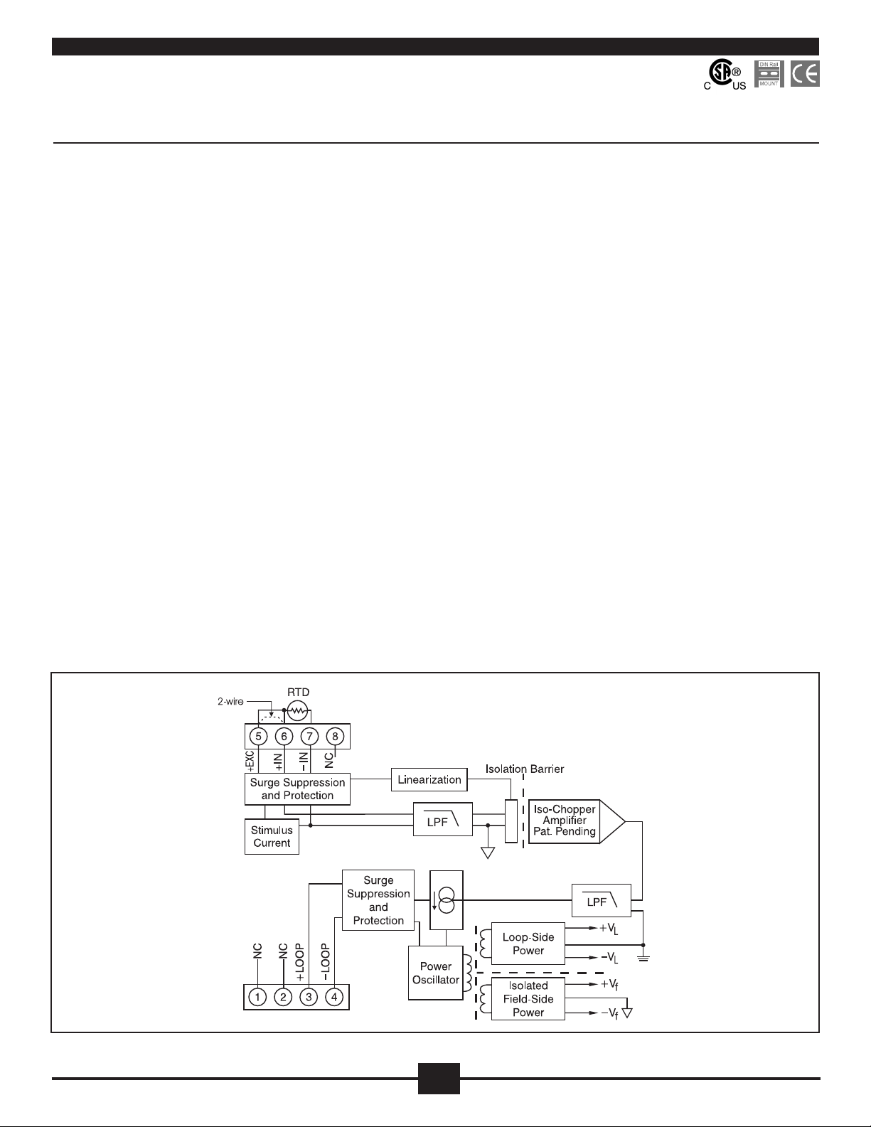
Each DRLP RTD input transmitter provides a single channel of RTD input
which is ltered, isolated, amplied, linearized, and converted to a process
current output (Figure 1). Signal ltering is accomplished with a ve-pole lter,
which provides 85dB of normal-mode rejection at 60Hz and 80dB at 50Hz.
An anti-aliasing pole is located on the eld side of the isolation barrier, and the
other four are on the process loop side. After the initial eld-side ltering, the
input signal is chopped by a proprietary chopper circuit. Isolation is provided by
transformer coupling, again using a proprietary technique to suppress transmission of common mode spikes or surges.
RTD excitation is provided from the transmitter using a precision current
source. The excitation currents are very small (0.26mA max for 100W Pt and
120W Ni) which minimizes self-heating of the RTD. Linearization is achieved by
creating a non-linear transfer function through the module itself. This non-linear
transfer function is congured at the factory and is designed to be equal and
opposite to the specic RTD non-linearity. Lead compensation is achieved by
matching two current paths thus canceling the effects of lead resistance.
The specications listed are for a 3-wire connection. A 2-wire connection of
the RTD to the module is also possible and is achieved by adding a jumper
between pin 5 (+EXC) and pin 6 (+IN) on the terminal block and connecting the
RTD leads between pin 6 (+IN) and pin 7 (-IN). The 2-wire connection nullies
the lead resistance compensation feature of the module.
Special input and output circuits on the DRLP transmitters provide protection
against accidental connection of power-line voltages up to 240VAC and against
transient events as dened by ANSI/IEEE C37.90.1. Signal and loop power
lines are secured to the module using screw terminals, which are in pluggable
terminal blocks for ease of system assembly and reconguration.
The modules have excellent stability over time and do not require recalibration,
however, zero and span settings are adjustable up to ±3% to accommodate
situations where ne-tuning is desired. The adjustments are made using
potentiometers located under the front panel label and are non-interactive for
ease of use.
Figure 1: DRLP-RTD Block Diagram
10
10
Page 10
Specifications Typical at T
=+25°C and +24V loop voltage
A
Module DRLP-RTD
Ordering Information
Module Input Range Accuracy
(1)
Input Range
Input Resistance
Normal
Power Off
Overload
Input Protection
Continuous
Transient
CMV, Input to Output
Continuous
Transient
CMR (50Hz or 60Hz)
NMR
Adjustability
Accuracy
Conformity
Stability
Offset
Gain
Sensor Excitation Current
Lead Resistance Effect
Noise
Output, 100kHz
Bandwidth, –3dB
Response Time, 90% Span
Output Range
Output Limits
Under-range
Over-range
Output Protection
Reverse Polarity
Over-voltage
Transient
Loop Supply Voltage
Loop Supply Sensitivity
Turn-On Delay
(1)
–200°C to +850°C (100W Pt)
–80°C to +320°C (120W Ni)
50MW
66kW
66kW
240Vrms max
ANSI/IEEE C37.90.1
1500Vrms max
ANSI/IEEE C37.90.1
160dB
85dB at 60Hz, 80dB at 50Hz
±3% Zero and Span
See Ordering Information
±0.025%
±50ppm/°C
±100ppm/°C
0.260mA
±0.02°C/W
3µArms
3Hz
165ms
4mA to 20mA
3mA
29mA
Continuous
240Vrms Continuous
ANSI/IEEE C37.90.1
10.8V to 60V
±0.0005%/V
400ms
100W Pt **
DRLP-RTD1
DRLP-RTD2
DRLP-RTD3
DRLP-RTD4
DRLP-RTD5
120W Ni **
DRLP-RTD6
**RTD Standards
–100°C to +100°C
(–148°F to +212°F)
0°C to +100°C
(+32°F to +212°F)
0°C to +200°C
(+32°F to +392°F)
0°C to +600°C
(+32°F to +1112°F)
0°C to +400°C
(+32°F to +752°F)
0°C to +300°C
(+32°F to +572°F)
Alpha
Type
100W Pt
120W Ni
NOTES:
(1) Includes conformity, hysteresis and repeatability.
Coefcient DIN JIS IEC
0.00385
0.00672
DIN 43760 JIS C 1604-1989 IEC 751
±0.1%
±0.1%
±0.1%
±0.1%
±0.1%
±0.1%
±0.2°C
±0.1°C
±0.2°C
±0.6°C
±0.4°C
±0.3°C
Environmental
Operating Temp. Range
Storage Temp. Range
Relative Humidity
Emissions EN61000-6-4
Radiated, Conducted
Immunity EN61000-6-2
RF
ESD, EFT
Mechanical Dimensions
(h)(w)(d)
Mounting
–40°C to +80°C
–40°C to +80°C
0 to 95% Noncondensing
ISM, Group 1
Class A
ISM, Group 1
Performance A ±0.5% Span Error
Performance B
2.95” x 0.89” x 4.13”
(75mm x 22.5mm x 105mm)
DIN EN 50022 –35x7.5 or –35x15 rail
11
11
Page 11
Potentiometer Input Transmitters
Interfaces to Potentiometers up to 10kW
•
Process Current Output
•
1500Vrms Transformer Isolation
•
ANSI/IEEE C37.90.1 Transient Protection
•
Input and Output Protected to 240VAC Continuous
•
Up to 60V Loop Voltage
•
160dB CMR
•
85dB NMR at 60Hz, 80dB at 50Hz
•
±0.03% Accuracy
•
±0.01% Linearity
•
Easily Mounts on Standard DIN Rail
•
CSA C/US Certied
•
CE Compliant
•
DRLP-P
DescriptionFeatures
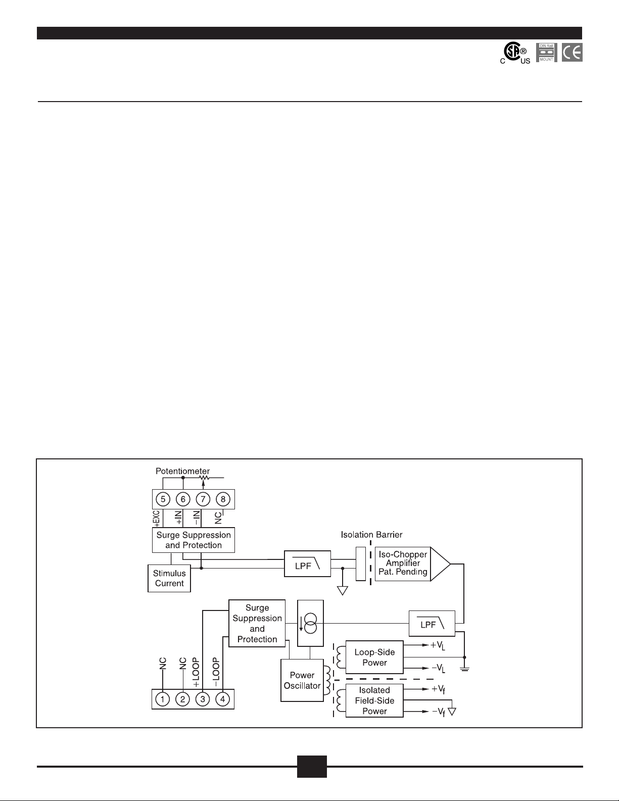
Each DRLP-P potentiometer input transmitter provides a single channel of
potentiometer input which is ltered, isolated, amplied, and converted to a
process current output (Figure 1). Signal ltering is accomplished with a vepole lter, which provides 85dB of normal-mode rejection at 60Hz and 80dB
at 50Hz. An anti-aliasing pole is located on the eld side of the isolation barrier, and the other four are on the process loop side. After the initial eld-side
ltering, the input signal is chopped by a proprietary chopper circuit. Isolation
is provided by transformer coupling, again using a proprietary technique to
suppress transmission of common mode spikes or surges.
Potentiometer excitation is provided from the transmitter using a precision
current source. The excitation current is small (less than 0.26mA) which
minimizes self-heating of the potentiometer. Lead compensation is achieved
by matching two current paths which cancels the effects of lead resistance.
Special input and output circuits on the DRLP-P transmitters provide protection against accidental connection of power-line voltages up to 240VAC and
against transient events as dened by ANSI/IEEE C37.90.1. Signal and loop
power lines are secured to the module using screw terminals, which are in
pluggable terminal blocks for ease of system assembly and reconguration.
The modules have excellent stability over time and do not require recalibration, however, zero and span settings are adjustable up to ±10% to accommodate situations where ne-tuning is desired. The adjustments are made
using potentiometers located under the front panel label and are non-interactive for ease of use.
Figure 1: DRLP-P Block Diagram
121313
12
Page 12
Specifications Typical at T
=+25°C and +24V loop voltage
A
Ordering Information
Module DRLP-P
Input Range
Input Resistance
Normal
Power Off
Overload
Input Protection
Continuous
Transient
CMV, Input to Output
Continuous
Transient
CMR (50Hz or 60Hz)
NMR
Adjustability
Accuracy
Conformity
Stability
Offset
Gain
Sensor Excitation Current
Lead Resistance Effect
Noise
Output, 100kHz
Bandwidth, –3dB
Response Time, 90% Span
(1)
0.26mA; 100W, 500W Sensor
±0.01W/W; 100W, 500W, 1kW Sensor
0W to 10kW
50MW
66kW
66kW
240Vrms max
ANSI/IEEE C37.90.1
1500Vrms max
ANSI/IEEE C37.90.1
160dB
85dB at 60Hz, 80dB at 50Hz
±10% Zero and Span
±0.03%
±0.01%
±50ppm/°C
±100ppm/°C
0.13mA; 1kW Sensor
0.065mA; 10kW Sensor
±0.02W/W; 10kW Sensor
3µArms
3Hz
165ms
Module Input Range
DRLP-P1
DRLP-P2
DRLP-P3
DRLP-P4
NOTES:
(1) Includes linearity, hysteresis and repeatability.
0 to 100W
0 to 500W
0 to 1kW
0 to 10kW
Output Range
Output Limits
Under-range
Over-range
Output Protection
Reverse Polarity
Over-voltage
Transient
Loop Supply Voltage
Loop Supply Sensitivity
Turn-On Delay
Environmental
Operating Temp. Range
Storage Temp. Range
Relative Humidity
Emissions EN61000-6-4
Radiated, Conducted
Immunity EN61000-6-2
RF
ESD, EFT
Mechanical Dimensions
(h)(w)(d)
Mounting
4mA to 20mA
3mA
29mA
Continuous
240Vrms Continuous
ANSI/IEEE C37.90.1
10.8V to 60V
±0.0005%/V
400ms
–40°C to +80°C
–40°C to +80°C
0 to 95% Noncondensing
ISM, Group 1
Class A
ISM, Group 1
Performance A ±0.5% Span Error
Performance B
2.95” x 0.89” x 4.13”
(75mm x 22.5mm x 105mm)
DIN EN 50022 –35x7.5 or –35x15 rail
Page 13
Non-Linearized Thermocouple Input Transmitters
Interfaces to Types J, K, T, E, R, S, B, and N
•
Thermocouples
Process Current Output
•
1500Vrms Transformer Isolation
•
ANSI/IEEE C37.90.1 Transient Protection
•
Input and Output Protected to 240VAC Continuous
•
Up to 60V Loop Voltage
•
160dB CMR
•
85dB NMR at 60Hz, 80dB at 50Hz
•
±0.05% Accuracy
•
±0.01% Linearity
•
Easily Mounts on Standard DIN Rail
•
CSA C/US Certied
•
CE Compliant
•
DRLP-ITC
DescriptionFeatures
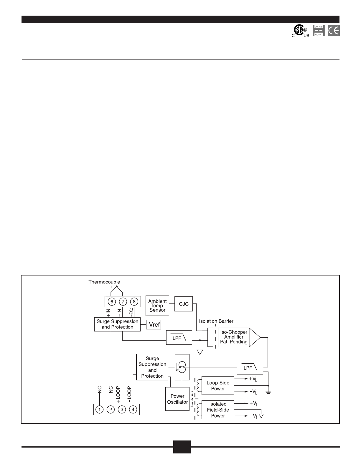
Each DRLP-ITC non-linearized thermocouple input transmitter provides a
single channel of thermocouple input which is ltered, isolated, amplied, and
converted to a process current output (Figure 1). Signal ltering is accomplished with a ve-pole lter, which provides 85dB of normal-mode rejection
at 60Hz and 80dB at 50Hz.An anti-aliasing pole is located on the eld side of
the isolation barrier, and the other four are on the process loop side. After the
initial eld-side ltering, the input signal is chopped by a proprietary chopper
circuit. Isolation is provided by transformer coupling, again using a proprietary
technique to suppress transmission of common mode spikes or surges.
The DRLP-ITC can interface to eight industry standard thermocouple types:
J, K, T, E, R, S, B and N. Each transmitter is cold-junction compensated to
correct for parasitic thermocouples formed by the thermocouple wire and
screw terminals on the transmitter. Upscale open thermocouple detection is
provided by circuitry. Downscale indication can be implemented by installing
a 47MW, ±20% resistor between screw terminals 6 (+IN) and 8 (-EXC) on the
input terminal block.
Special input and output circuits on the DRLP-ITC transmitters provide
protection against accidental connection of power-line voltages up to 240VAC
and against transient events as dened by ANSI/IEEE C37.90.1. Loop power
lines are secured to the module using screw terminals, which are in pluggable
terminal blocks for ease of system assembly and reconguration. Transmitter zero and span settings are adjustable up to ±10%. The adjustments are
made using potentiometers located under the front panel label and are noninteractive for ease of use.
Figure 1: DRLP-ITC Block Diagram
141515
14
Page 14
Specifications Typical at T
=+25°C and +24V loop voltage
A
Ordering Information
Module DRLP-ITC
Input Range
Input Bias Current
Input Resistance
Normal
Power Off
Overload
Input Protection
Continuous
Transient
CMV, Input to Output
Continuous
Transient
CMR (50Hz or 60Hz)
NMR
Adjustability
Accuracy
Stability
Offset
Gain
Cold Junction Compensation
Accuracy, +25°C
Accuracy, 0°C to +50°C
Accuracy, –40°C to +80°C
Open Input Response
Open Input Detection Time
Noise
Output, 100kHz
Bandwidth, –3dB
Response Time, 90% Span
Output Range
Output Limits
Under-range
Over-range
Output Protection
Reverse Polarity
Over-voltage
Transient
Loop Supply Voltage
Loop Supply Sensitivity
Turn-On Delay
Environmental
Operating Temp. Range
Storage Temp. Range
Relative Humidity
Emissions EN61000-6-4
Radiated, Conducted
Immunity EN61000-6-2
RF
ESD, EFT
(1)
Standard thermocouple temperature limits
as per NIST monograph 175, ITS-90
–25nA
50MW
66kW
66kW
240Vrms max
ANSI/IEEE C37.90.1
1500Vrms max
ANSI/IEEE C37.90.1
160dB
85dB at 60Hz, 80dB at 50Hz
±10% Zero and Span
See Ordering Information
±40ppm/°C
±60ppm/°C
±0.25°C
±0.50°C
±1.25°C
Upscale
< 5s
3µArms
3Hz
165ms
4mA to 20mA
2.8mA
29mA
Continuous
240Vrms Continuous
ANSI/IEEE C37.90.1
10.8V to 60V
±0.0005%/V
400ms
–40°C to +80°C
–40°C to +80°C
0 to 95% Noncondensing
ISM, Group 1
Class A
ISM, Group 1
Performance A ±0.5% Span Error
Performance B
TC
Module
DRLP-ITC-J
DRLP-ITC-K
DRLP-ITC-T
DRLP-ITC-E
DRLP-ITC-R
DRLP-ITC-S
DRLP-ITC-B
DRLP-ITC-N
‡Thermocouple Alloy Combinations
Standards: DIN IEC 584, ANSI MC96-1-82, JIS C 1602-1981
Type
J
K
T
E
R
S
B
N
‡
Input Range Accuracy
–100°C to +760°C
(–148°F to +1400°F)
–100°C to +1350°C
(–148°F to +2462°F)
–100°C to +400°C
(–148°F to +752°F)
0°C to +900°C
(+32°F to +1652°F)
0°C to +1750°C
(+32°F to +3182°F)
0°C to +1750°C
(+32°F to +3182°F)
0°C to +1800°C
(+32°F to +3272°F)
–100°C to +1300°C
(–148°F to +2372°F)
±0.05%
±0.05%
±0.05%
±0.05%
±0.05%
±0.05%
±0.05%
±0.05%
Type Material
J
Iron vs. Copper-Nickel
K
Nickel-Chromium vs. Nickel-Aluminum
T
Copper vs. Copper-Nickel
E
Nickel-Chromium vs. Copper-Nickel
R
Platinum-13% Rhodium vs. Platinum
S
Platinum-10% Rhodium vs. Platinum
B
Platinum-30% Rhodium vs. Platinum-6% Rhodium
N
Nickel-14.2% Chromium-1.4% Silicon vs. Nickel-4.4%
Silicon- 0.1% Magnesium
NOTES:
(1) Includes conformity, hysteresis, repeatability and CJC error.
(1)
±0.43°C
±0.73°C
±0.25°C
±0.45°C
±0.88°C
±0.88°C
±0.90°C
±0.70°C
Mechanical Dimensions
(h)(w)(d)
Mounting
2.95” x 0.89” x 4.13”
(75mm x 22.5mm x 105mm)
DIN EN 50022 –35x7.5 or –35x15 rail
Page 15
DRLP-LTC
Linearized Thermocouple Input Transmitters
Features
Interfaces to Types J, K, T, E, R, S, B, and N
•
Thermocouples
Linearizes Thermocouple Signal
•
Process Current Output
•
1500Vrms Transformer Isolation
•
ANSI/IEEE C37.90.1 Transient Protection
•
Input and Output Protected to 240VAC Continuous
•
Up to 60V Loop Voltage
•
160dB CMR
•
85dB NMR at 60Hz, 80dB at 50Hz
•
±0.10% Accuracy
•
Easily Mounts on Standard DIN Rail
•
CSA C/US Certied
•
CE Compliant
•
Description
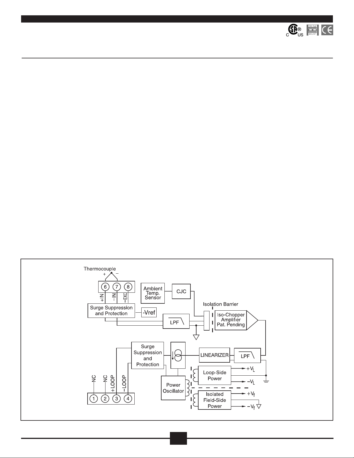
Each DRLP-LTC thermocouple input transmitter provides a single channel
of thermocouple input which is ltered, isolated, amplied, linearized, and
converted to a process current output (Figure 1). Signal ltering is accomplished with a ve-pole lter, which provides 85dB of normal-mode rejection
at 60Hz and 80dB at 50Hz. An anti-aliasing pole is located on the eld side of
the isolation barrier, and the other four are on the process loop side. After the
initial eld-side ltering, the input signal is chopped by a proprietary chopper
circuit. Isolation is provided by transformer coupling, again using a proprietary
technique to suppress transmission of common mode spikes or surges.
Linearization is achieved by creating a non-linear transfer function through the
module itself. This non-linear transfer function is congured at the factory and
is designed to be equal and opposite to the thermocouple non-linearity.
The DRLP-LTC can interface to eight industry standard thermocouple types:
J, K, T, E, R, S, B and N. Each transmitter is cold-junction compensated to
correct for parasitic thermocouples formed by the thermocouple wire and
screw terminals on the transmitter. Upscale open thermocouple detection is
provided by circuitry. Downscale indication can be implemented by installing a
47MW, ±20% resistor between screw terminals 6 (+IN) and 8 (-EXC) on the
input terminal block.
Special input and output circuits on the DRLP-LTC transmitters provide
protection against accidental connection of power-line voltages up to 240VAC
and against transient events as dened by ANSI/IEEE C37.90.1. Loop power
lines are secured to the module using screw terminals, which are in pluggable
terminal blocks for ease of system assembly and reconguration. Transmitter
zero and span settings are adjustable up to ±3%. The adjustments are made
using potentiometers located under the front panel label and are non-interactive for ease of use.
Figure 1: DRLP-LTC Block Diagram
16
16
Page 16
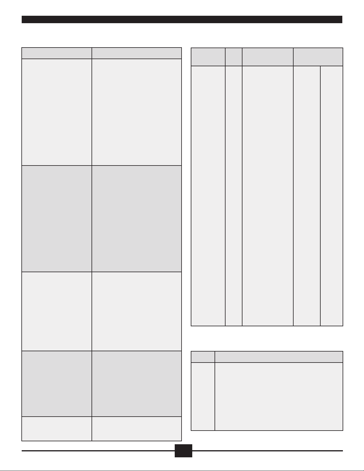
Specifications Typical at T
=+25°C and +24V loop voltage
A
Ordering Information
Module DRLP-LTC
Input Range
Input Bias Current
Input Resistance
Normal
Power Off
Overload
Input Protection
Continuous
Transient
CMV, Input to Output
Continuous
Transient
CMR (50Hz or 60Hz)
NMR
Adjustability
Accuracy
Stability
Offset
Gain
Cold Junction Compensation
Accuracy, +25°C
Accuracy, 0°C to +50°C
Accuracy, –40°C to +80°C
Open Input Response
Open Input Detection Time
Noise
Output, 100kHz
Bandwidth, –3dB
Response Time, 90% Span
(1)
Standard thermocouple temperature limits
as per NIST monograph 175, ITS-90
–25nA
50MW
66kW
66kW
240Vrms max
ANSI/IEEE C37.90.1
1500Vrms max
ANSI/IEEE C37.90.1
160dB
85dB at 60Hz, 80dB at 50Hz
±3% Zero and Span
See Ordering Information
±60ppm/°C
±80ppm/°C
±0.25°C
±0.50°C
±1.25°C
Upscale
< 5s
3µArms
3Hz
165ms
Module
DRLP-LTC-J1
DRLP-LTC-J2
DRLP-LTC-J3
DRLP-LTC-K1
DRLP-LTC-K2
DRLP-LTC-K3
DRLP-LTC-K4
DRLP-LTC-T1
DRLP-LTC-T2
DRLP-LTC-E
DRLP-LTC-R
TC
Type‡Input Range Accuracy
J
J
J
K
K
K
K
T
T
E
R
0°C to +760°C
(+32°F to +1400°F)
–100°C to +300°C
(–148°F to +572°F)
0°C to +500°C
(+32°F to +932°F)
0°C to +1000°C
(+32°F to +1832°F)
0°C to +500°C
(+32°F to +932°F)
–100°C to +1350°C
(–148°F to +2462°F)
0°C to +1200°C
(32°F to +2192°F)
–100°C to +400°C
(–148°F to +752°F)
0°C to +200°C
(+32°F to +392°F)
0°C to +1000°C
(+32°F to +1832°F)
+500°C to +1750°C
(+932°F to +3182°F)
±0.1% span
±0.1% span
±0.1% span
±0.1% span
±0.1% span
±0.1% span
±0.1% span
±0.1% span
±0.1% span
±0.1% span
±0.1% span
±0.76°C
±0.40°C
±0.50°C
±1.00°C
±0.50°C
±1.45°C
±1.20°C
±0.50°C
±0.20°C
±1.00°C
±1.25°C
(1)
Output Range
Output Limits
Under-range
Over-range
Output Protection
Reverse Polarity
Over-voltage
Transient
Loop Supply Voltage
Loop Supply Sensitivity
Turn-On Delay
Environmental
Operating Temp. Range
Storage Temp. Range
Relative Humidity
Emissions EN61000-6-4
Radiated, Conducted
Immunity EN61000-6-2
RF
ESD, EFT
Mechanical Dimensions
(h)(w)(d)
Mounting
4mA to 20mA
2.8mA
29mA
Continuous
240Vrms Continuous
ANSI/IEEE C37.90.1
10.8V to 60V
±0.0005%/V
400ms
–40°C to +80°C
–40°C to +80°C
0 to 95% Noncondensing
ISM, Group 1
Class A
ISM, Group 1
Performance A ±0.5% Span Error
Performance B
2.95” x 0.89” x 4.13”
(75mm x 22.5mm x 105mm)
DIN EN 50022 –35x7.5 or –35x15 rail
DRLP-LTC-S
DRLP-LTC-B
DRLP-LTC-N
‡Thermocouple Alloy Combinations
Standards: DIN IEC 584, ANSI MC96-1-82, JIS C 1602-1981
S
+500°C to +1750°C
(+932°F to +3182°F)
B
+500°C to +1800°C
(+932°F to +3272°F)
N
–100°C to +1300°C
(–148°F to +2372°F)
±0.1% span
±0.1% span
±0.1% span
±1.25°C
±1.30°C
±1.40°C
Type Material
J
Iron vs. Copper-Nickel
K
Nickel-Chromium vs. Nickel-Aluminum
T
Copper vs. Copper-Nickel
E
Nickel-Chromium vs. Copper-Nickel
R
Platinum-13% Rhodium vs. Platinum
S
Platinum-10% Rhodium vs. Platinum
B
Platinum-30% Rhodium vs. Platinum-6% Rhodium
N
Nickel-14.2% Chromium-1.4% Silicon vs. Nickel-4.4%
Silicon- 0.1% Magnesium
NOTES: (1) Includes conformity, hysteresis, repeatability and CJC error.
17
17
Page 17
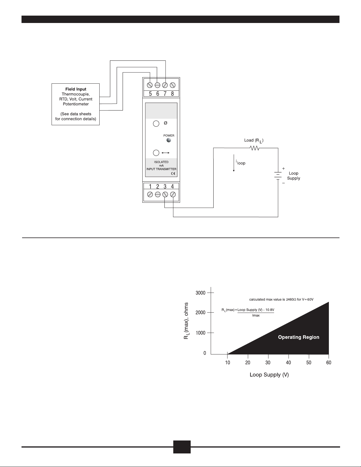
DRLP Wiring Diagram
DRLP Loop Drive Capability
The DRLP Transmitter’s wide range of Loop Supply Voltage (10.8V to 60V)
makes it a versatile device which can be used in most any current loop. The
maximum loop resistance is determined by subtracting the transmitter’s
minimum loop supply voltage from the total loop supply voltage and dividing
the result by the maximum loop current (see graph).
The low Loop Supply Voltage of 10.8V allows the DRLP to be used in applications with low output power supplies and the high Loop Supply Voltage of 60V
allows use in applications with long distance current loops.
18
18
Page 18
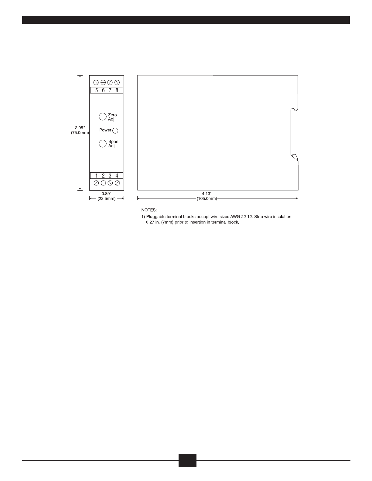
DRLP Module Dimensions
19
19
Page 19

WARRANTY/DISCLAIMER
OMEGA ENGINEERING, INC. warrants this unit to be free of defects in materials and workmanship for a
period of 13 months from date of purchase. OMEGA’s WARRANTY adds an additional one (1) month
grace period to the normal one (1) year product warranty to cover handling and shipping time. This
ensures that OMEGA’s customers receive maximum coverage on each product.
If the unit malfunctions, it must be returned to the factory for evaluation. OMEGA’s Customer Service
Department will issue an Authorized Return (AR) number immediately upon phone or written request.
Upon examination by OMEGA, if the unit is found to be defective, it will be repaired or replaced at no
charge. OMEGA’s WARRANTY does not apply to defects resulting from any action of the purchaser,
including but not limited to mishandling, improper interfacing, operation outside of design limits,
improper repair, or unauthorized modification. This WARRANTY is VOID if the unit shows evidence of
having been tampered with or shows evidence of having been damaged as a result of excessive corrosion;
or current, heat, moisture or vibration; improper specification; misapplication; misuse or other operating
conditions outside of OMEGA’s control. Components in which wear is not warranted, include but are not
limited to contact points, fuses, and triacs.
OMEGA is pleased to offer suggestions on the use of its various products. However,
OMEGA neither assumes responsibility for any omissions or errors nor assumes liability for any
damages that result from the use of its products in accordance with information provided by
OMEGA, either verbal or written. OMEGA warrants only that the parts manufactured by the
company will be as specified and free of defects. OMEGA MAKES NO OTHER WARRANTIES OR
REPRESENTATIONS OF ANY KIND WHATSOEVER, EXPRESSED OR IMPLIED, EXCEPT THAT OF
TITLE, AND ALL IMPLIED WARRANTIES INCLUDING ANY WARRANTY OF MERCHANTABILITY
AND FITNESS FOR A PARTICULAR PURPOSE ARE HEREBY DISCLAIMED. LIMITATION OF
LIABILITY: The remedies of purchaser set forth herein are exclusive, and the total liability of
OMEGA with respect to this order, whether based on contract, warranty, negligence,
indemnification, strict liability or otherwise, shall not exceed the purchase price of the
co mponent upon which l iability is b ased. In no event shall OMEGA be liable for
consequential, incidental or special damages.
CONDITIONS: Equipment sold by OMEGA is not intended to be used, nor shall it be used: (1) as a “Basic
Component” under 10 CFR 21 (NRC), used in or with any nuclear installation or activity; or (2) in medical
applications or used on humans. Should any Product(s) be used in or with any nuclear installation or
activity, medical application, used on humans, or misused in any way, OMEGA assumes no responsibility
as set forth in our basic WARRANTY/DISCLAIMER language, and, additionally, purchaser will indemnify
OMEGA and hold OMEGA harmless from any liability or damage whatsoever arising out of the use of the
Product(s) in such a manner.
RETURN REQUESTS/INQUIRIES
Direct all warranty and repair requests/inquiries to the OMEGA Customer Service Department. BEFORE
RETURNING ANY PRODUCT(S) TO OMEGA, PURCHASER MUST OBTAIN AN AUTHORIZED RETURN
(AR) N UMBE R FRO M OME G A’S CUS T OME R SERVIC E DEPA RT M ENT ( IN OR D ER T O AVOI D
PROCESSING DELAYS). The assigned AR number should then be marked on the outside of the return
package and on any correspondence.
The purchaser is responsible for shipping charges, freight, insurance and proper packaging to prevent
breakage in transit.
FOR WARRANTY
RETURNS, please have the
following information available BEFORE
contacting OMEGA:
1. Purchase Order number under which the product
was PURCHASED,
2. Model and serial number of the product under
warranty, and
3. Repair instructions and/or specific problems
relative to the product.
FOR NON-WARRANTY REPAIRS,
consult OMEGA
for current repair charges. Have the following
information available BEFORE contacting OMEGA:
1. Purchase Order number to cover the COST
of the repair,
2. Model and serial number of the product, and
3. Repair instructions and/or specific problems
relative to the product.
OMEGA’s policy is to make running changes, not model changes, whenever an improvement is possible. This affords
our customers the latest in technology and engineering.
OMEGA is a registered trademark of OMEGA ENGINEERING, INC.
© Copyright 2012 OMEGA ENGINEERING, INC. All rights reserved. This document may not be copied, photocopied,
reproduced, translated, or reduced to any electronic medium or machine-readable form, in whole or in part, without the
prior written consent of OMEGA ENGINEERING, INC.
Page 20

M5110/0312
Where Do I Find Everything I Need for
Process Measurement and Control?
OMEGA…Of Course!
Shop online at omega.com
SM
TEMPERATURE
Thermocouple, RTD & Thermistor Probes, Connectors, Panels & Assemblies
Wire: Thermocouple, RTD & Thermistor
Calibrators & Ice Point References
Recorders, Controllers & Process Monitors
Infrared Pyrometers
PRESSURE, STRAIN AND FORCE
Transducers & Strain Gages
Load Cells & Pressure Gages
Displacement Transducers
Instrumentation & Accessories
FLOW/LEVEL
Rotameters, Gas Mass Flowmeters & Flow Computers
Air Velocity Indicators
Turbine/Paddlewheel Systems
Totalizers & Batch Controllers
pH/CONDUCTIVITY
pH Electrodes, Testers & Accessories
Benchtop/Laboratory Meters
Controllers, Calibrators, Simulators & Pumps
Industrial pH & Conductivity Equipment
DATA ACQUISITION
Data Acquisition & Engineering Software
Communications-Based Acquisition Systems
Plug-in Cards for Apple, IBM & Compatibles
Data Logging Systems
Recorders, Printers & Plotters
HEATERS
Heating Cable
Cartridge & Strip Heaters
Immersion & Band Heaters
Flexible Heaters
Laboratory Heaters
ENVIRONMENTAL
MONITORING AND CONTROL
Metering & Control Instrumentation
Refractometers
Pumps & Tubing
Air, Soil & Water Monitors
Industrial Water & Wastewater Treatment
pH, Conductivity & Dissolved Oxygen Instruments
 Loading...