

Page 1
Specications
Inputs:
Sensor Types: see Table 9
Ranges: Any span within Range in Table 9
Impedance: > 1.0M ohms typical for t/c and mV inputs
RTD Excitation: < 0.3mA
Burnout Detection: up or down scale
CJC Error: < +0.1°C max. (Instant AccuracyTM ensures the output is
within +0.5°C of rated accuracy 30 seconds after powering
:
Output
Voltage
Ranges: 0-5V or 2-10V (default)
Drive: 10mA (1000 ohm load min.)
Current
Ranges: 0-20mA or 4-20mA (default)
Drive: 15V (750 ohms max.)
Isolation:
1800VDC or peak AC between input output & power
Conguration:
SW1: Pushbutton, input and output ranging
SW2: Linearization, Burnout, Output (voltage or current), and
initialization mode
SW3: Input Type
Accuracy:
Input (A/D): see Table 9
Linearization: < +0.05% of accuracy range, max.
Output: < +10µA for current output
< +5mV for voltage output
Thermal Stability:
CJC: + 0.01°C / °C change in ambient, max.
Zero: + 0.0075% of full scale /°C change in ambient, max.
Span: + 0.0075% of full scale /°C change in ambient, max.
Long Term: + 0.1% max. over a 9 month period
Response Time:
400mSec, typical
Turn On Time:
< 5 seconds to establish output within 99% or 0.5°C of nal value
LED Indicator:
Power (green):
On when power is on
Flashes for t/c burnout ash
Input (yellow):
Flashes for out of range
OMEGA ENGINEERING, INC., warrants this unit to be free of defects in materials and workmanship for a period of 13 months from date of purchase.
omega.com info@omega.
Servicing North America:
U.S.A.:
Omega Engineering, Inc., One Omega Drive,
P.O. Box 4047, Stamford, CT 06907-0047 USA
Toll-Free: 1-800-826-6342 (USA & Canada only)
Customer Service: 1-800-622-2378
(USA & Canada only)
Engineering Service: 1-800-872-9436
(USA & Canada only)
Tel: (203) 359-1660
Fax: (203) 359-7700
e-mail: info @omega.com
For Other Locations Visit
omega.com/worldwide
The information contained in this document is
believed to be correct, but OMEGA accepts no
liability for any errors it contains, and reserves
the right to alter specifications without notice.
com
OMEGA’s WARRANTY adds an additional one (1) month grace period to the normal one (1) year product warranty to cover handling and shipping
time. This ensures that OMEGA’s customers receive maximum coverage on each product.
If the unit malfunctions, it must be returned to the factory for evaluation. OMEGA’s Customer Service Department will issue an Authorized Return
(AR) number immediately upon phone or written request. Upon examination by OMEGA, if the unit is found to be defective, it will be repaired
or replaced at no charge. OMEGA’s WARRANTY does not apply to defects resulting from any action of the purchaser, including but not limited to
mishandling, improper interfacing, operation outside of design limits, improper repair, or unauthorized modification. This WARRANTY is VOID if
the unit shows evidence of having been tampered with or shows evidence of having been damaged as a result of excessive corrosion; or current,
heat, moisture or vibration; improper specification; misapplication; misuse or other operating conditions outside of OMEGA’s control. Components
in which wear is not warranted, include but are not limited to contact points, fuses, and triacs.
OMEGA is pleased to offer suggestions on the use of its various products. However, OMEGA neither assumes responsibility for any omissions
or errors nor assumes liability for any damages that result from the use of its products in accordance with information provided by OMEGA,
either verbal or written. OMEGA warrants only that the parts manufactured by the company will be as specified and free of defects. OMEGA
MAKES NO OTHER WARRANTIES OR REPRESENTATIONS OF ANY KIND WHATSOEVER, EXPRESSED OR IMPLIED, EXCEPT THAT OF TITLE, AND
ALL IMPLIED WARRANTIES INCLUDING ANY WARRANTY OF MERCHANTABILITY AND FITNESS FOR A PARTICULAR PURPOSE ARE HEREBY
DISCLAIMED. LIMITATION OF LIABILITY: The remedies of purchaser set forth herein are exclusive, and the total liability of OMEGA with respect to
this order, whether based on contract, warranty, negligence, indemnification, strict liability or otherwise, shall not exceed the purchase price of
the component upon which liability is based. In no event shall OMEGA be liable for consequential, incidental or special damages.
CONDITIONS: Equipment sold by OMEGA is not intended to be used, nor shall it be used: (1) as a “Basic Component” under 10 CFR 21 (NRC), used
in or with any nuclear installation or activity; or (2) in medical applications or used on humans. Should any Product(s) be used in or with any nuclear
installation or activity, medical application, used on humans, or misused in any way, OMEGA assumes no responsibility as set forth in our basic
WARRANTY/DISCLAIMER language, and, additionally, purchaser will indemnify OMEGA and hold OMEGA harmless from any liability or damage
whatsoever arising out of the use of the Product(s) in such a manner.
Direct all warranty and repair requests/inquiries to the OMEGA Customer Service Department. BEFORE RETURNING ANY PRODUCT(S) TO OMEGA,
PURCHASER MUST OBTAIN AN AUTHORIZED RETURN (AR) NUMBER FROM OMEGA’S CUSTOMER SERVICE DEPARTMENT (IN ORDER TO AVOID
PROCESSING DELAYS). The assigned AR number should then be marked on the outside of the return package and on any correspondence.
The purchaser is responsible for shipping charges, freight, insurance and proper packaging to prevent breakage in transit.
FOR WARRANTY RETURNS, please have the following
information available BEFORE contacting OMEGA.
1. Purchase order number which the product was PURCHASED,
2. Model and serial number of the product under warranty, and
3. Repair instructions and/or specific problems relative to
the product.
OMEGA’s policy is to make running changes, not model changes, whenever an improvement is possible. This affords custo mers the late st
technology and engineering. OMEGA is a registered trademark of OMEGA ENGINEERING, INC.
© COPYRIGHT 2015 OMEGA ENGINEERING, INC. All rights reserved. This document may not be copied, photocopied, translated, or reduced to
any electronic medium-readable form, in whole or in part, without the prior written consent of OMEGA ENGINEERING, INC.
(red):
Flashes for switch setting error
Calibration: 1 green, 1 yellow and 1 red LEDs indicate steps in
ranging process
Common Mode Rejection:
120dB at DC
> 90dB at 60Hz
ESD Susceptibility:
Capable of meeting IEC 801-2 level 3 (8kV)
Humidity (non-condensiing):
Operating: 15 to 95% @ 45°C
Soak: 90% RH for 24 Hours @ 60°C
Temperature:
Operating: -25°C to +65°C (-13 to 149°F)
Storage: -25°C to +70°C (-13 to 158°F)
Power:
100 to 240 Vac ±10%, 50 to 400 Hz, 2.5 W max
Shipping Weight:
0.5 lbs.
Wire Terminal:
Socketed screw terminals for 12-22AWG
Agency Approvals
UL recognized per standard UL508 (File No. E99755).
CE Compliance per EMC directive 89/336/EEC and Low Voltage 73/23/EEC.
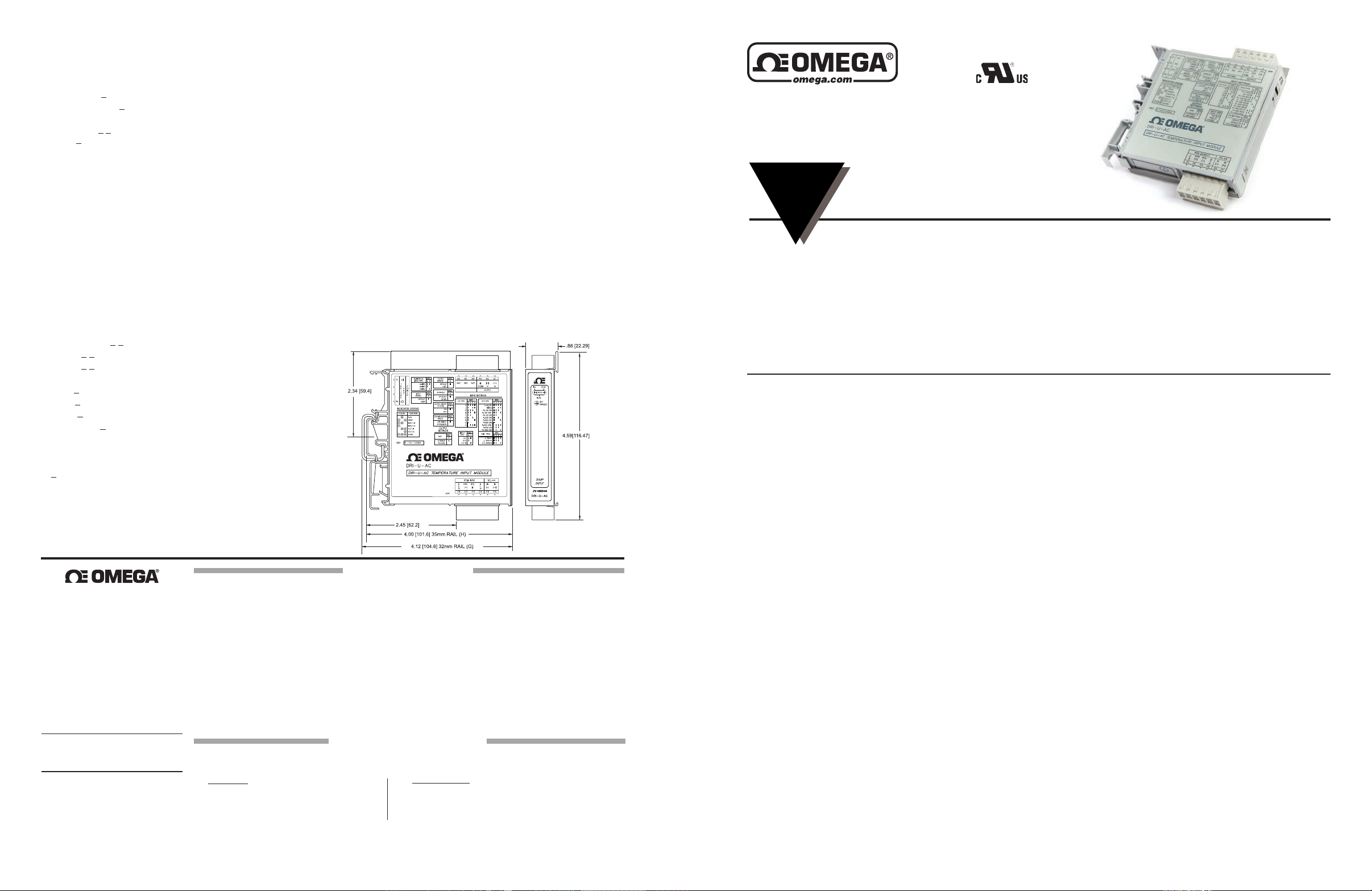
Dimensions
WARRANTY/DISCLAIMER
RETURN REQUESTS/INQUIRIES
FOR NON-WARRANTY RETURNS, consult OMEGA for current repair
charges. Have the following information available BEFORE contacting
OMEGA.
1. Purchase Order number to cover the COST of the repair,
2. Model and serial number of the product and
3. Repair instructions and/or specific problems relative to the product.
DRI-U-AC
AC Powered Universal Input
DIN Rail Signal Conditioner
INSTRUCTION
SHEET
Shop online at omega.comSM e-mail: [email protected]
For latest product manuals: www.omegamanual.info
Rapid Accuracy Adjustment
Field Congurable Input Ranges
DIP Switch Conguration
Eliminates Ground Loops
Description
The DRI-U-AC is a DC powered, DIN rail mount, RTD,
thermocouple, mV or Ohm input signal conditioner with 1800V
isolation between input, output and power. The eld congurable
input and output offers exible, wide ranging capability for most
temperature signal conditioning applications.
The DRI-U-AC is congured via DIP switch for the thermocouple
type (B, C, E, J, K, N, R, S, T) or the RTD type (Pt, Ni & Cu).
Additionally, functions such as signal linearization, up or down
scale burnout, number of RTD leads (2, 3, 4) and voltage or
current output are also set via dip switches (see Tables).
Rapid Accuracy Adjustment
Accuracy and performance are maximized during warmup
and during changes in ambient temperature. The patented
cold-junction compensation technique utilizes two temperature
sensors to measure the differential temperature near the
terminal block. Using heat transfer calculations with the
measured differential temperature and the known thermal
conductivity of the PCB, the terminal junction temperature
is determined with extreme accuracy. Even during unstable
thermal states such as start-up, ambient temperature changes
or changing load or power, the DRI-U-AC performs extremely
accurate thermocouple temperature measurement.
System performance and productivity are improved due to
reduced warm up time, fewer temperature measurement errors
and tighter process control for higher quality. Most signicantly,
it allows calibration to be checked quickly and accurately without
the effects of rapid ambient temperature changes due to opening
a control panel door, which often causes erroneous readings and
miscalibrations; a common cause of measurement errors.
Touch Calibration Technology
Touch Calibration technology allows easy eld ranging for any
of the thermocouple or RTD input types. For example, the dip
M5472/0915
Provides an Isolated DC Output
in Proportion to the Temperature Signal Input
Touch Calibration Technology
High Density DIN Rail Mounting
Universal AC power 85 to 265 VAC
Plug-in Terminals
switch congured range for the J type thermocouple is -210
to 760°C. Using a thermocouple simulator as a reference, the
model DRI-U-AC could be ranged for 0 to 50°C or 0 to 500°C by
simply applying the desired minimum and maximum input levels
and pushing the range button to store the levels in non-volatile
memory. The output is ranged by applying an input signal to
achieve an accurate output level and pushing the range button.
Applications
The model DRI-U-AC eld congurable thermocouple or RTD
input isolator is useful in eliminating ground loops and interfacing
temperature sensors to data acquisition and control systems.
Three-way isolation completely eliminates ground loops from
any source. Isolation protects expensive SCADA systems
from ground faults and allows the noise reduction benets of
grounded thermocouples or sensors to be realized.
The DRI-U-AC employs the latest analog to digital
signal processing technology and advanced low-power
microprocessors. Instant Accuracy cold-junction-compensation
(CJC) of thermocouples, and lead length compensation for
RTDs ensures an extremely accurate and stable signal for
virtually any temperature sensor to DC signal conversion.
High density DIN rail mounting offers a very compact solution
and saves valuable panel space. Power is delivered to the
DRI-U-AC using the exclusive ACPB rail which reduces wiring
requirements and the need to daisy-chain power. Plug-in
terminals ensure easy installation and low Mean-Time-ToRepair (MTTR).
Diagnostic LEDS
The DRI-U-AC is equipped with front panel LEDs for input power
(green-on), input overrange and underrange; input open circuit
(yellow-on); and switch setting error (red-on).
Page 2
Conguration
RTD Type
SW2
1 2
3-Wire
4-Wire
2-Wire
Key: = 1 = On or Closed
Output
SW2
3
Current
Voltage
Key: = 1 = On or Closed
Input Range
SW2
4
Default
User Defined
Key: = 1 = On or Closed
Output Range
SW2
5
Default
User Defined
Key: = 1 = On or Closed
T/C Type
SW3
Input
Range
Accuracy
Range
Input (A/D)
Accuracy
3 4 5 6
R
0 to +1760°C +200 to +1760°C +/-1.0°C
J
-210 to +760°C -100 to +760°C +/-0.25°C
S
0 to +1760°C +400 to +1760°C +/-1.0°C
B
0 to +1800°C +400 to +1800°C +/-2.0°C
T
-270 to +400°C 0 to +400°C +/-0.25°C
K
-270 to +1370°C -100 to +1370°C +/-0.3°C
N
-270 to +1300°C 70 to +1300°C +/-0.4°C
C
0 to +2320°C 0 to +2320°C +/-0.5°C
E
-270 to +1000°C -100 to +1000°C +/-0.25°C
RTD Type
SW3
Input Range Input (A/D) Accuracy
3 4 5 6
Cu-9.035
-40 to +260°C +/-0.25°C
Ni-120 067
-80 to +320°C +/-0.15°C
Pt-100 385
-200 to +850°C +/-0.15°C
Pt-100 3911
-200 to +630°C +/-0.15°C
Pt-100 392
-200 to +630°C +/-0.15°C
Pt-200 385
-200 to +850°C +/-0.20°C
Pt-200 392
-200 to +630°C +/-0.20°C
Pt-500 385
-200 to +850°C +/-0.20°C
Pt-500 3911
-200 to +630°C +/-0.20°C
Pt-500 392
-200 to +630°C +/-0.20°C
Pt-1000 385
-200 to +850°C +/-0.20°C
mV & Ohm
Type
SW3
Input Range Accuracy Range
Input (A/D)
Accuracy
Minimum
Span
3 4 5 6
+/- 90mV
-90 to +90mV -90 to +90mV +/-12uV 3mV
+/- 900mV
-100 to 900mV -100 to 900mV +/-25uV 3mV
0 to 4000 Ohms
10 to 4000 Ohms 10 to 4000 Ohms +/-1.0 Ohms 10 Ohms
Key: = 1 = ON or Closed
Burnout Detection
SW2
6
Upscale
Downscale
Key: = 1 = On or Closed
Output Linear
to Temperature
SW2
7
On
Off
Key: = 1 = On or Closed
Configuration
Mode
SW2
8
By DIP Switch
By PC
Key: = 1 = On or Closed
Input Type
SW3
1 2
Thermocouple
RTD
mV or Ohms
Key: = 1 = On or Closed
Terminal Connection Terminal Connection
A1 Current Output (+) C3 RTD Input (-) or Resistance
A2 Voltage Output (+) C4 RTD Return
A3 Output Common (-) C5 T/C Input (-) or mV (-)
A4 Not Used C6 T/C Input (+) or mV (+)
A5 DC Power (+) P1 Not Used
A6 DC Power (-) P2 Not Used
C1 RTD Sense P3 DC Power (+)
C2 RTD Input (+) or Resistance P4 DC Power (-)
The DRI-U-AC can be congured via DIP switchs for a wide
variety of temperature input ranges for RTD, thermocouple, ohm
and millivolt sensors. Inputs can be offset by >90% or adjusted
down to <10% of the full scale span.
Unless a specic customer range is ordered, the factory presets
the DRI-U-AC as follows:
Input Type: Thermocouple, J-Type
Input Range: 0 to 500°C
Burnout: Up Scale
Output Range: 4/20mA
Refer to the tables for other I/O ranges.
1. With power off, snap off the faceplate by lifting the right edge
away from the heatsink.
2. For RTD or Resistance inputs, set position 1 and 2 of SW2 for
2, 3 or 4 wire resistance input (see Table 1). For thermocouple
inputs these switches ignored and can be in any position.
3. Congure the output for voltage or current using position 3
of SW2 (see Table 2).
5. If the output range desired is the full scale range for the output
type (e.g. 4-20mA or 2-10V), then set position 5 of SW2 to ON
for either of the full scale default output ranges (see Table 4). If
conguration of a sub-range is preferred (e.g. 12-20mA or 1-5V),
then set position 5 of SW2 to OFF (or open) to enable use of
the ranging pushbutton adjustment.
6. Set Burnout detection with position 6 of SW2 (see Table 6).
The ON position (up scale) will force the output beyond full scale
when the t/c input is open circuit. The OFF position (down scale)
will force the output below 0% when the input is open circuit.
7. Set the t/c Linearization function with position 7 of SW2 (see
Table 7). The ON position will provide an output linear to the
temperature input signal. The OFF position will provide an output
directly proportional to the thermoelectric (mV) input (i.e. not
linearized to temperature).
Note: The unit must be congured with linearization turned ON. Once
the conguration is saved, linearization can then be turned OFF.
8. Set the Conguration Mode with position 8 of SW2 (see Table
8). The ON position is for DIP switch conguration. The OFF
position is for conguring via PC using a serial interface cable
(consult factory regarding cable and software).
Calibration
The DRI-U-AC is a microprocessor based circuit with internal
references that are factory calibrated to better than 0.000005V.
For this reason the DRI-U-AC does not need eld calibration,
but it can be congured (ranged) in the eld for virtually any
temperature to DC I/O combination.
For best results ranging should be performed in the operating
installation, allowing at least 30 minutes for thermal equilibrium of
the system. If ranging on a test bench is preferred, then an output
load equal to the input impedance of the device connected to the
output is recommended, along with a 30 minute warm up period.
1. After conguring the unit, install the module onto a piece of
DIN rail and the ACPB rail mounting combination. See the ACPB
rail data sheet for details.
2. Connect the input to a calibrated thermocouple simulator or
resistance source and the output to a voltage or current meter.
Apply power and allow the system to reach thermal equilibrium
(approx. 30 minutes).
3. Adjust the input signal to the desired maximum and observe
that the green LED is on. Push the CAL button and hold it down
for more than 5 seconds (until the yellow and red LEDs are on).
Note: To quit the calibration mode and reset the unit, push the
CAL button and hold for more than 5 seconds. Or, wait for more
than ve minutes and the unit will time-out and automatically
reset to the previously stored calibration.
4. Push the CAL button momentarily (the yellow and green LEDs
will now be on).
5. Apply the maximum input signal level, then push the CAL
button to store. The yellow LED will now be on.
6. Apply the minimum input signal level, then push the CAL button to store. The green and red LEDs will now be on.
7. Adjust the input signal while monitoring the output signal until
the output is at the desired maximum level (e.g. 20.00mA), then
push the CAL button to store (the red LED will be on).
8. Adjust the input signal while monitoring the output signal until
the output is at the desired minimum level (e.g. 4.00mA), then
push the CAL button to store (the yellow, green and red LEDs
will be on).
9. To nish calibration, push the CAL button once again. The
green LED will be on if the input is within the calibrated range.
4. If the input range desired is the full scale range for the input
type (e.g. Pt100 Ohm = -200°C to 850°C), then set position 4
of SW2 to ON (or closed) for this default range (see Table 3). If
conguration of a sub-range is preferred (e.g. Pt100 Ohm, 0 to
500°C), then set position 4 of SW2 to OFF (or open) to enable
use of the ranging pushbutton adjustment.
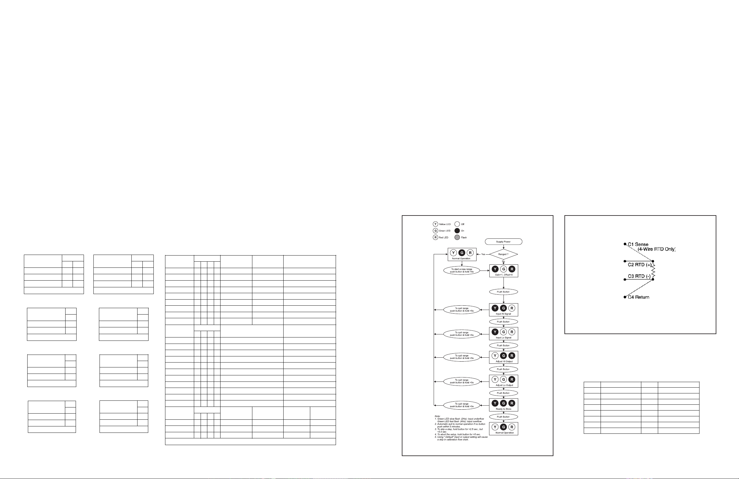
Table 1: RTD Type
Table 2: Output Type
Table 3: Input Range Type*
Table 4: Output Range Type*
*Default for Outputs is either 2-10V or 4-20mA. Default for Inputs is
the “Input Range” specied in Table 9. Note that if the input or output
is set for default, then the input or output calibration will be skipped in
the pushbutton programming sequence.
Table 7: Output Linearization
Table 5: Input Type
Table 6: Burnout Detection
Table 8: Cong Mode
9. Set the Input Type with position 1 and 2 of SW3 (see Table 5).
10. Set the specic RTD, thermocouple, millivolt or resistance
input with position 3 through 6 of SW3 (see Table 9).
Table 9: Input Select
Input to Output error at 25°C is less than or equal to the Input Accuracy, plus the Linearization
Accuracy, plus the Output Accuracy (plus the CJC Error for T/C Inputs).
Figure 2: RTD Wiring Detail
Figure 1: DRI-U-AC Calibration Flow Chart
 Loading...