

Page 1
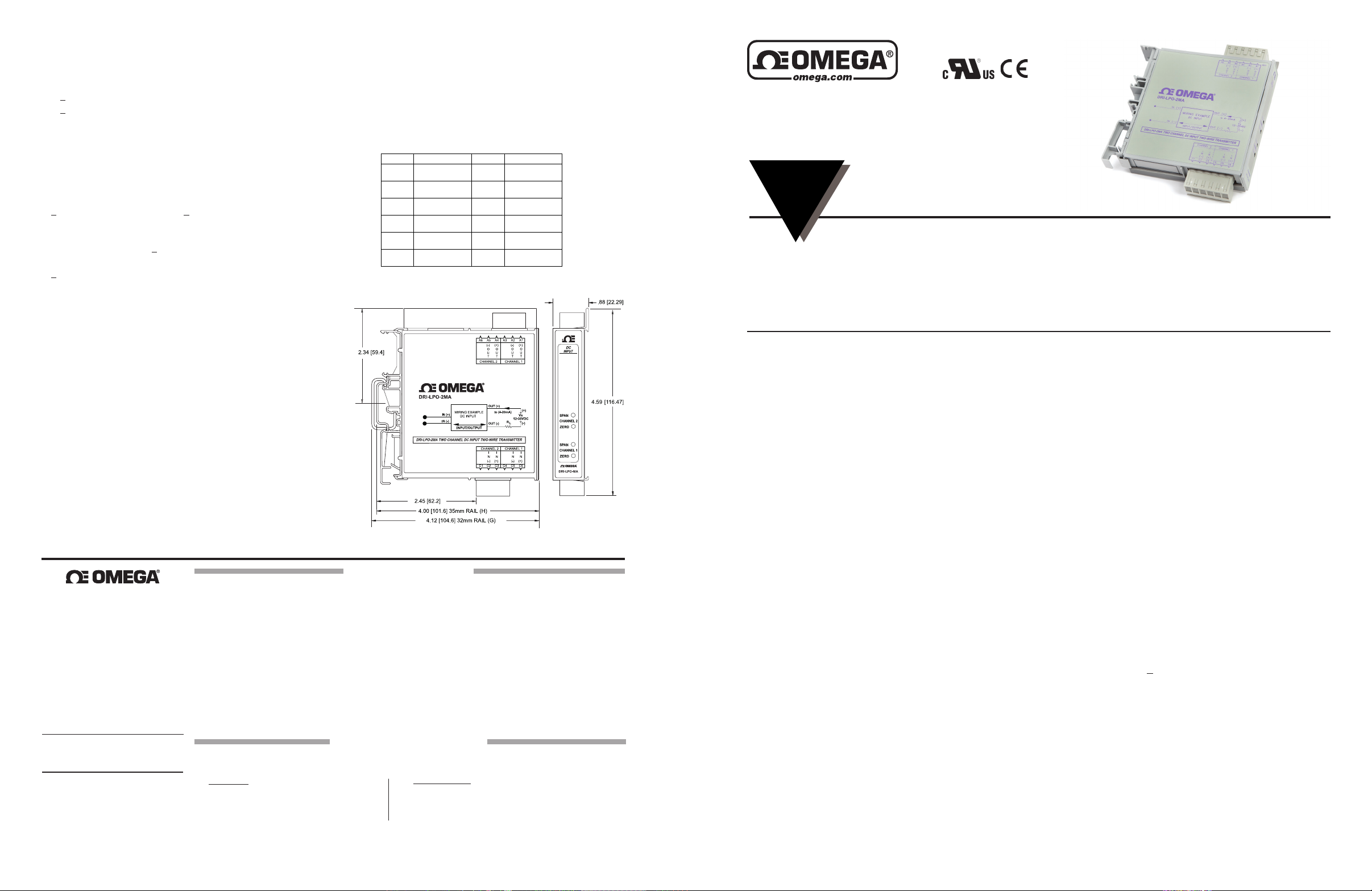
Terminal Connection Terminal Connection
A1
Channel 1
Power & Output (+)
C1 Not Connected
A2
Channel 1
Power & Output (-)
C2
Channel 2
DC Input (-)
A3 Not Connected C3
Channel 2
DC Input (+)
A4
Channel 2
Power & Output (+)
C4 Not Connected
A5
Channel 2
Power & Output (-)
C5
Channel 1
DC Input (-)
A6 Not Connected C6
Channel 1
DC Input (+)
Specications
Input:
Ranges: see below
Impedance:
>100K ohms (voltage inputs)
< 20 ohms (20mA Inputs),
Protection: withstands up to 24VDC (current input), 120VAC
(voltage input) without damage
Output Range:
4-20mA
Supply Voltage Range:
12 to 35VDC, each channel
Output Accuracy:
< 0.1% of full-scale input typical, < 0.2% max. @23oC including
linearity, repeatability and hysteresis
Adjustability:
Front accessed 10 turn, + 5% of span for zero and span, typical
Stability:
< 0.025%/oC of full-scale maximum
Meets IEC 801-2 level 2 (4kV)
ESD Susceptibility:
Meets IEC 801-2 level 2 (4kV)
Isolation:
1800VDC or peak AC between input and output and channel to
channel
Response Time:
100mSec typical (10 to 90%)
Temperature:
Operating: -40 to 80oC (-40 to 176oF)
Storage: -40 to 80oC (-40 to 176oF)
Humidity (non-condensing):
Operating: 15 to 90% (@45oC)
DRI-LPO-MA: 1 Channel; 4-20mA input; 4-20mA outputs
DRI-LPO-V: 1 Channel; 0-10Vdc input; 4-20mA output
DRI-LPO-2MA: 2 Channel; 4-20mA inputs; 4-20mA outputs
omega.com info@omega.
com
Servicing North America:
U.S.A.:
Omega Engineering, Inc., One Omega Drive,
P.O. Box 4047, Stamford, CT 06907-0047 USA
Toll-Free: 1-800-826-6342 (USA & Canada only)
Customer Service: 1-800-622-2378
(USA & Canada only)
Engineering Service: 1-800-872-9436
(USA & Canada only)
Tel: (203) 359-1660
Fax: (203) 359-7700
e-mail: info @omega.com
For Other Locations Visit
omega.com/worldwide
The information contained in this document is
believed to be correct, but OMEGA accepts no
liability for any errors it contains, and reserves
the right to alter specifications without notice.
Wire Terminals:
Socketed screw terminals for 12-22 AWG
Weight :
0.34lbs
Agency Approvals:
UL recognized per standard UL508 (File No. E99775).
CE conformance per EMC directive 89/336/EEC and low voltage
73/23/ EEC (Input <75VDC)
Dimensions
OMEGA ENGINEERING, INC., warrants this unit to be free of defects in materials and workmanship for a period of 13 months from date of purchase.
OMEGA’s WARRANTY adds an additional one (1) month grace period to the normal one (1) year product warranty to cover handling and shipping
time. This ensures that OMEGA’s customers receive maximum coverage on each product.
If the unit malfunctions, it must be returned to the factory for evaluation. OMEGA’s Customer Service Department will issue an Authorized Return
(AR) number immediately upon phone or written request. Upon examination by OMEGA, if the unit is found to be defective, it will be repaired
or replaced at no charge. OMEGA’s WARRANTY does not apply to defects resulting from any action of the purchaser, including but not limited to
mishandling, improper interfacing, operation outside of design limits, improper repair, or unauthorized modification. This WARRANTY is VOID if
the unit shows evidence of having been tampered with or shows evidence of having been damaged as a result of excessive corrosion; or current,
heat, moisture or vibration; improper specification; misapplication; misuse or other operating conditions outside of OMEGA’s control. Components
in which wear is not warranted, include but are not limited to contact points, fuses, and triacs.
OMEGA is pleased to offer suggestions on the use of its various products. However, OMEGA neither assumes responsibility for any omissions
or errors nor assumes liability for any damages that result from the use of its products in accordance with information provided by OMEGA,
either verbal or written. OMEGA warrants only that the parts manufactured by the company will be as specified and free of defects. OMEGA
MAKES NO OTHER WARRANTIES OR REPRESENTATIONS OF ANY KIND WHATSOEVER, EXPRESSED OR IMPLIED, EXCEPT THAT OF TITLE, AND
ALL IMPLIED WARRANTIES INCLUDING ANY WARRANTY OF MERCHANTABILITY AND FITNESS FOR A PARTICULAR PURPOSE ARE HEREBY
DISCLAIMED. LIMITATION OF LIABILITY: The remedies of purchaser set forth herein are exclusive, and the total liability of OMEGA with respect to
this order, whether based on contract, warranty, negligence, indemnification, strict liability or otherwise, shall not exceed the purchase price of
the component upon which liability is based. In no event shall OMEGA be liable for consequential, incidental or special damages.
CONDITIONS: Equipment sold by OMEGA is not intended to be used, nor shall it be used: (1) as a “Basic Component” under 10 CFR 21 (NRC), used
in or with any nuclear installation or activity; or (2) in medical applications or used on humans. Should any Product(s) be used in or with any nuclear
installation or activity, medical application, used on humans, or misused in any way, OMEGA assumes no responsibility as set forth in our basic
WARRANTY/DISCLAIMER language, and, additionally, purchaser will indemnify OMEGA and hold OMEGA harmless from any liability or damage
whatsoever arising out of the use of the Product(s) in such a manner.
Direct all warranty and repair requests/inquiries to the OMEGA Customer Service Department. BEFORE RETURNING ANY PRODUCT(S) TO OMEGA,
PURCHASER MUST OBTAIN AN AUTHORIZED RETURN (AR) NUMBER FROM OMEGA’S CUSTOMER SERVICE DEPARTMENT (IN ORDER TO AVOID
PROCESSING DELAYS). The assigned AR number should then be marked on the outside of the return package and on any correspondence.
The purchaser is responsible for shipping charges, freight, insurance and proper packaging to prevent breakage in transit.
FOR WARRANTY RETURNS, please have the following
information available BEFORE contacting OMEGA.
1. Purchase order number which the product was PURCHASED,
2. Model and serial number of the product under warranty, and
3. Repair instructions and/or specific problems relative to
the product.
OMEGA’s policy is to make running changes, not model changes, whenever an improvement is possible. This affords c ustomers the latest
technology and engineering. OMEGA is a registered trademark of OMEGA ENGINEERING, INC.
© COPYRIGHT 2015 OMEGA ENGINEERING, INC. All rights reserved. This document may not be copied, photocopied, translated, or reduced to
any electronic medium-readable form, in whole or in part, without the prior written consent of OMEGA ENGINEERING, INC.
WARRANTY/DISCLAIMER
RETURN REQUESTS/INQUIRIES
FOR NON-WARRANTY RETURNS, consult OMEGA for current repair
charges. Have the following information available BEFORE contacting
OMEGA.
1. Purchase Order number to cover the COST of the repair,
2. Model and serial number of the product and
3. Repair instructions and/or specific problems relative to the product.
DRI-LPO SERIES
Output Loop Powered DIN Rail Multi-Channel
DC Input Isolating, 2-Wire Transmitter
INSTRUCTION
SHEET
Shop online at omega.comSM e-mail: [email protected]
For latest product manuals: www.omegamanual.info
Multi-Channel Design
Prevents Ground Loops
Standard Input Ranges
Description
The DRI-LPO Series is a DIN rail mount, DC input, single or
dual channel, two-wire transmitter. Each channel accepts a DC
voltage or current input and provides an isolated 4-20mA output.
Each channel is fully isolated (1800VDC) from input to output and
channel to channel.
The DRI-LPO Series features plug-in screw terminals for easy
installation and low Mean-Time-To-Repair (MTTR). Two or
more modules can slide together and interlock for solid, high
density mounting. This is accomplished by removing either
the foot, or the adjacent unit's faceplate (for right-hand side or
left-hand hand side mounting, respectively). The module to be
attached will easily slide on to the side of the mounted unit.
Application
DC input, two-wire transmitters are used to isolate and convert
a DC voltage or current into a proportional 4-20mA signal. Twowire transmitters are primarily used in remote locations near the
sensor since they reduce the probability of signal errors and
save wiring costs by utilizing the two power wires to send the
4-20mA signal. The current signal is usually monitored by a
control system or displayed for an operator.
Typically, DC voltages or currents from various eld instruments
(e.g. level, ow, pressure and position sensors) are used to
monitor and control a manufacturing process. Voltage signals
can only run a short distance to a panel without errors caused
by noise or lead resistance in the wires. These sensor (voltage)
signal wires are usually terminated at the two-wire transmitter
and converted into a 4-20mA signal which is highly immune to
noise and not affected by lead resistance, both of which can
cause signicant errors in voltage signals transmitted over long
distances.
The 1800VDC isolation capability of the DRI-LPO Series
prevents ground loops from causing errors in DC voltage
or current signals and can reduce susceptibility to Radio
Frequency Interference (RFI). Isolation also provides protection
from high voltages and current spikes which can damage
M5480/0815
Provides One or Two Isolated 4-20mA Output Current
Loops in Proportion to One or Two DC Inputs
High Density DIN Rail Mounting
Plug-in Terminals
Output Loop Powered from 12 to 35VDC
expensive Supervisory Control And Data Acquisition (SCADA)
equipment, such as a PLC or DCS.
Operation
The DRI-LPO Series operates as a two-wire transmitter; each
channel derives its power from a 12-35VDC source connected in
series with the 4-20mA output loop. Typically a 24VDC source is
used for power, allowing 12VDC (600 ohms @ 20mA) for other
devices connected in series in the current loop. The outputs of
the DRI-LPO Series are isolated from the inputs and protected
from reverse polarity. Zero and span pots are provided for
each channel to calibrate the output to the input source (+/-5%).
Standard input ranges (see Table) are calibrated to rated
accuracy. One range per module; one or two channels per
module.
Calibration
1. Connect the input to a calibrated DC source. Connect the
output in series to a voltage source capable of supplying at least
20mA and a milliamp current meter.
Note: The voltage source (Vs) must be sufficient to
accommodate all other device loads (RL) in the current loop:
Vs > 12 + (0.02RL)
2. Set the calibrator to the specied minimum DC input value
and adjust the zero potentiometer for 4mA output.
3. Set the calibrator to the specied maximum DC input value
and adjust the span potentiometer for 20mA output.
4. Repeat steps 2 and 3, as necessary.
Page 2

PAGE
PAGE
INTENTIONALLY
BLANK
INTENTIONALLY
BLANK
 Loading...