

Page 1
Output :
Terminal Connection Terminal Connection
A1 Output (+) C3 Input Voltage (Line)
A2 Output (-) C4 Not Used
A3 Not Used C5 Input (Neutral)
A4 Not Used C6 Input Current (Line)
A5 Not Used P1 AC Power (Hot)
A6 Not Used P2 Not Used
C1 Not Used P3 Not Used
C2 Not Used P4 AC Power (Neutral)
Voltage:
Output: 0-5V, 0-10V
Source Impedance: <10 ohms
Drive: 10mA, max. (1K ohms, min. @ 10V)
Current:
Output: 0-1mA, 0-20mA, 4-20mA
Source Impedance: >100K ohms
Compliance:
0-1mA; 7.5V, max. (7.5K ohms, max.)
0-20mA; 12V, max. (600 ohms, max.)
4-20mA; 12V, max. (600 ohms, max.)
LED Indication
RUN (green):
On when unit is powered
ashesat8Hzwheninputis7%abovemax.
INPUT (yellow):
Onwhilecalibratingtheinputlevel
OUTPUT (red):
Onwhilecalibratingtheoutputlevel
Accuracy (Including Linearity & Hysteresis):
+0.1%ofspan,typical,+0.2%max.
+0.5%ofspan,maximum(100mVrange)
Stability:
+0.025%/°Cofselectedinputspan,typical.
Response Time (10 to 90%):
250mSec., typical.
Common Mode Rejection:
DCto60Hz:90dB
Isolation:
1800VDCbetweeninput,outputandpower.
EMC Compliance (CE Mark):
Emmissions:EN50081-1;Immunity:EN50082-2;Safety:
EN50178
Humidity (Non-Condensing):
Operating:15to95%@45°C
Soak:90%for24hours@65°C
Temperature Range:
Operating:0to55°C(32to131°F)
Storage:-25to70°C(-13to158°F)
Power:
Consumption: 1.5W typical, 2.5W max.
Range:100to240VAC±10%,50to400Hz
Wire Terminations:
Screwterminalsfor12-22AWG
Shipping Weight:
0.48lbs.
Agency Approvals:
ULrecognizedperstandardUL508(FileNo.E99775)
CEComplianceperEMCdirective89/3/36EECandLowVoltage73/23/EEC.
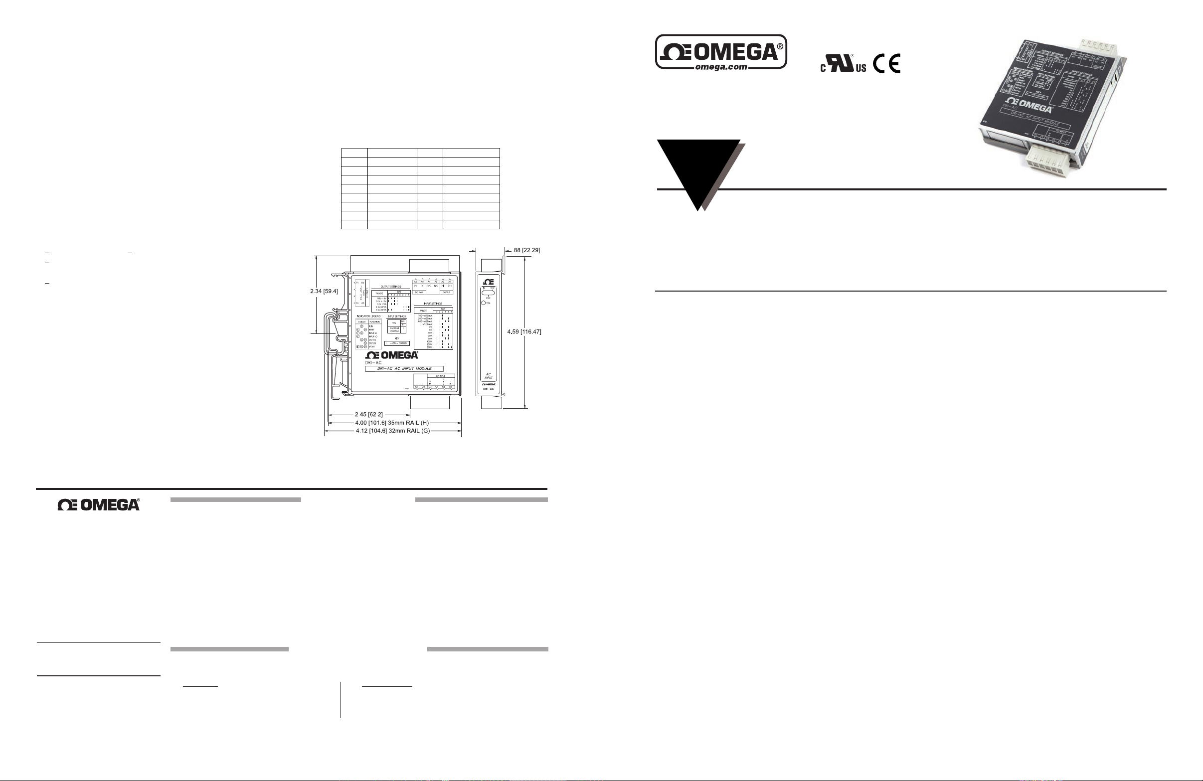
Dimensions
DRI-AC
AC Powered AC Input
DIN Rail Signal Conditioner
INSTRUCTION
SHEET
Shop online at omega.comSM e-mail: [email protected]
For latest product manuals: www.omegamanual.info
EliminatesGroundLoops
FieldCongurableInputRanges
FieldCongurableOutputRanges
TouchCalibrationTechnology
Description
The DRI-AC is a DIN rail mount, AC input signal conditioner
with1800VDCisolationbetweeninput,outputandpower.The
eldcongurableinputandoutputoffersexible,wideranging
capabilityforscaling,convertingorbufferingACinputsranging
from5mAto100mAACor50mVto300VAC.
For current inputs above 100mA, it is recommended that an
inputshuntresistorbeusedandtheDRI-ACbeconguredfor
theproperinputrange.Forexample,a5Acurrenttransformer
output can use the C006 shunt resistor (0.1 ohm, 5W) with the
inputoftheDRI-ACsetfor0-500mVAC.
The DC output of the DRI-AC is proportional to the average
ofthe fully-rectiedACinputsignal,and iscalibratedforsine
wavesbetween40-400Hz.
M5475/0715
Provides an Isolated DC Output
in Proportion to an AC Input
DIN Rail Mounting with IQRL
UniversalACPower85to265VAC
Plug-in Terminals
scaleoutput.Inputrangessuchas180-200Vor0-20Varepossible
using the 0-200V range.
Advanceddigitaltechnologycombinedwith ASIC technology
allowstheDRI-ACtobeeld congured for virtually any AC
inputtoDCoutputwithinthelimitsspecied.
Application
The DRI-AC is useful in applications requiring an isolated,
conditionedDCoutputfromanACsignal.Typicalapplications
includeenergymanagement,loadshedding,motorcurrent/load
monitoring,lockedrotordetection,isolationanddataacquisition.
Theoutputofthe DRI-AC can drive adigitalmeterfordirect
displayorcaninterfacewithalarmorcontroldevicesincluding
PLCs and computers.
omega.com info@omega.
Servicing North America:
U.S.A.:
Omega Engineering, Inc., One Omega Drive,
P.O. Box 4047, Stamford, CT 06907-0047 USA
Toll-Free: 1-800-826-6342 (USA & Canada only)
Customer Service: 1-800-622-2378
(USA & Canada only)
Engineering Service: 1-800-872-9436
(USA & Canada only)
Tel: (203) 359-1660
Fax: (203) 359-7700
e-mail: info @omega.com
For Other Locations Visit
omega.com/worldwide
The information contained in this document is
believed to be correct, but OMEGA accepts no
liability for any errors it contains, and reserves
the right to alter specifications without notice.
com
OMEGA ENGINEERING, INC., warrants this unit to be free of defects in materials and workmanship for a period of 13 months from date of purchase.
OMEGA’s WARRANTY adds an additional one (1) month grace period to the normal one (1) year product warranty to cover handling and shipping
time. This ensures that OMEGA’s customers receive maximum coverage on each product.
If the unit malfunctions, it must be returned to the factory for evaluation. OMEGA’s Customer Service Department will issue an Authorized Return
(AR) number immediately upon phone or written request. Upon examination by OMEGA, if the unit is found to be defective, it will be repaired
or replaced at no charge. OMEGA’s WARRANTY does not apply to defects resulting from any action of the purchaser, including but not limited to
mishandling, improper interfacing, operation outside of design limits, improper repair, or unauthorized modification. This WARRANTY is VOID if
the unit shows evidence of having been tampered with or shows evidence of having been damaged as a result of excessive corrosion; or current,
heat, moisture or vibration; improper specification; misapplication; misuse or other operating conditions outside of OMEGA’s control. Components
in which wear is not warranted, include but are not limited to contact points, fuses, and triacs.
OMEGA is pleased to offer suggestions on the use of its various products. However, OMEGA neither assumes responsibility for any omissions
or errors nor assumes liability for any damages that result from the use of its products in accordance with information provided by OMEGA,
either verbal or written. OMEGA warrants only that the parts manufactured by the company will be as specified and free of defects. OMEGA
MAKES NO OTHER WARRANTIES OR REPRESENTATIONS OF ANY KIND WHATSOEVER, EXPRESSED OR IMPLIED, EXCEPT THAT OF TITLE, AND
ALL IMPLIED WARRANTIES INCLUDING ANY WARRANTY OF MERCHANTABILITY AND FITNESS FOR A PARTICULAR PURPOSE ARE HEREBY
DISCLAIMED. LIMITATION OF LIABILITY: The remedies of purchaser set forth herein are exclusive, and the total liability of OMEGA with respect to
this order, whether based on contract, warranty, negligence, indemnification, strict liability or otherwise, shall not exceed the purchase price of
the component upon which liability is based. In no event shall OMEGA be liable for consequential, incidental or special damages.
CONDITIONS: Equipment sold by OMEGA is not intended to be used, nor shall it be used: (1) as a “Basic Component” under 10 CFR 21 (NRC), used
in or with any nuclear installation or activity; or (2) in medical applications or used on humans. Should any Product(s) be used in or with any nuclear
installation or activity, medical application, used on humans, or misused in any way, OMEGA assumes no responsibility as set forth in our basic
WARRANTY/DISCLAIMER language, and, additionally, purchaser will indemnify OMEGA and hold OMEGA harmless from any liability or damage
whatsoever arising out of the use of the Product(s) in such a manner.
Direct all warranty and repair requests/inquiries to the OMEGA Customer Service Department. BEFORE RETURNING ANY PRODUCT(S) TO OMEGA,
PURCHASER MUST OBTAIN AN AUTHORIZED RETURN (AR) NUMBER FROM OMEGA’S CUSTOMER SERVICE DEPARTMENT (IN ORDER TO AVOID
PROCESSING DELAYS). The assigned AR number should then be marked on the outside of the return package and on any correspondence.
The purchaser is responsible for shipping charges, freight, insurance and proper packaging to prevent breakage in transit.
FOR WARRANTY RETURNS, please have the following
information available BEFORE contacting OMEGA.
1. Purchase order number which the product was PURCHASED,
2. Model and serial number of the product under warranty, and
3. Repair instructions and/or specific problems relative to
the product.
OMEGA’s policy is to make running changes, not model changes, whenever an improvement is possible. This affords custo mers the latest
technology and engineering. OMEGA is a registered trademark of OMEGA ENGINEERING, INC.
© COPYRIGHT 2015 OMEGA ENGINEERING, INC. All rights reserved. This document may not be copied, photocopied, translated, or reduced to
any electronic medium-readable form, in whole or in part, without the prior written consent of OMEGA ENGINEERING, INC.
WARRANTY/DISCLAIMER
RETURN REQUESTS/INQUIRIES
FOR NON-WARRANTY RETURNS, consult OMEGA for current repair
charges. Have the following information available BEFORE contacting
OMEGA.
1. Purchase Order number to cover the COST of the repair,
2. Model and serial number of the product and
3. Repair instructions and/or specific problems relative to the product.
Touch Calibration Technology
TheDRI-ACutilizesTouchCalibrationtechnologywhichgreatly
simplies calibration. The thermal drift and mechanical variabilityofthe potentiometershasbeen removedandreplaced
with a digitally stable circuit. Once the unit is congured via
DIPswitchesforvoltageor current,thepushbuttonisused to
preciselycalibratetheminimumandmaximumlevels.
Tosettheinput level within the dipswitchconguredrange,
simply apply the high input signal (voltage or current) and push
theCALbutton.ThelowinputsignalisthenappliedandpushingtheCALbuttonagainstoresthelowinputsignal.Thehigh
and low input levels are stored in nonvolatile memory and correspond to the high and low output levels. These output levels
are precisely adjusted using the input signal.
Touch Calibration technology enables precise calibration and
providesmorethan90%offsetofthezerovalueandadjustment
downto10%ofthefullscaleinputspanformostofthe16switch
selectable input ranges. For example, the dipswitch congured
0-200Vinputrangecouldbecalibratedviapushbuttonfor0-80V
(i.e.60%spanreduction)oroffsettoarangeof120-200V(i.e.
60%offsetand60%spanreduction).Iftheoutputwascongured
for0-10V,then120-200Vinputwouldcorrespondtothe0-10Vfull
Diagnostic LEDS
The DRI-AC has three diagnostic LEDs. The green (RUN) LED
isusedfordiagnosticstoindicatethatpowerison.Itwillash
quicklyiftheinputsignalisabovethecalibratedrangeorslowly
iftheinputsignalisbelowrange.Itisoncontinuouslywhenthe
unitisfunctioningwithinthecalibratedrange.
Theyellow(INPUT)LEDisonwhilecalibratingtheinputlevel.
Thered(OUTPUT)LEDisonwhilecalibratingtheoutputlevel.
Conguration
The DRI-AC can be congured for input ranges from 50mV
to300Vor5mAto 100mA,with>90% inputoffset orit will
adjust down to <10% of full scale input span (except on the
100mV/10mArangein which maximumoffsetorgain adjustmentis50%).
Unless a specic custom calibration is specied, the factory
presetstheDRI-ACasfollows:
Input Range: 0 -500mV
CalibratedOutput: 4-20mA
ForotherI/Oranges,refertothetables.
Page 2
WARNING: Do not change switch settings with power applied.
Severe damage will result!
1. Withpower off,snapoffthefaceplatebyliftingtheright edge
away from the heatsink. Slide theheatsink forward and off the
module.
2.ChoosethedesiredrangefromTables1-3.Returntheheatsink
to its original position and attach the faceplate before beginning
calibration.
Calibration
Forbestresults,calibrationshouldbeperformedintheoperating
installation,allowingatleastonehourforthermal stabilityofthe
system. If pre-calibration on a test bench is preferred, then an
outputloadequaltotheinputimpedanceofthedeviceconnected
to the DRI-AC output is recommended, along with a 1 hour warm
up period.
1.ForbestresultsinstallthemoduleontoapieceofDINrailor
theACPBrailmountingaccessoriesifdesired.SeetheACPB
railDatasheetfordetails.
Note:AnACPBrailisrequired to power the modules.See
orderinginformation.
2.ConnecttheinputtoacalibratedACsourceandtheoutput
to a voltage or current meter. Apply power and allow the system
toreachthermalequilibrium(approx.20minutes).
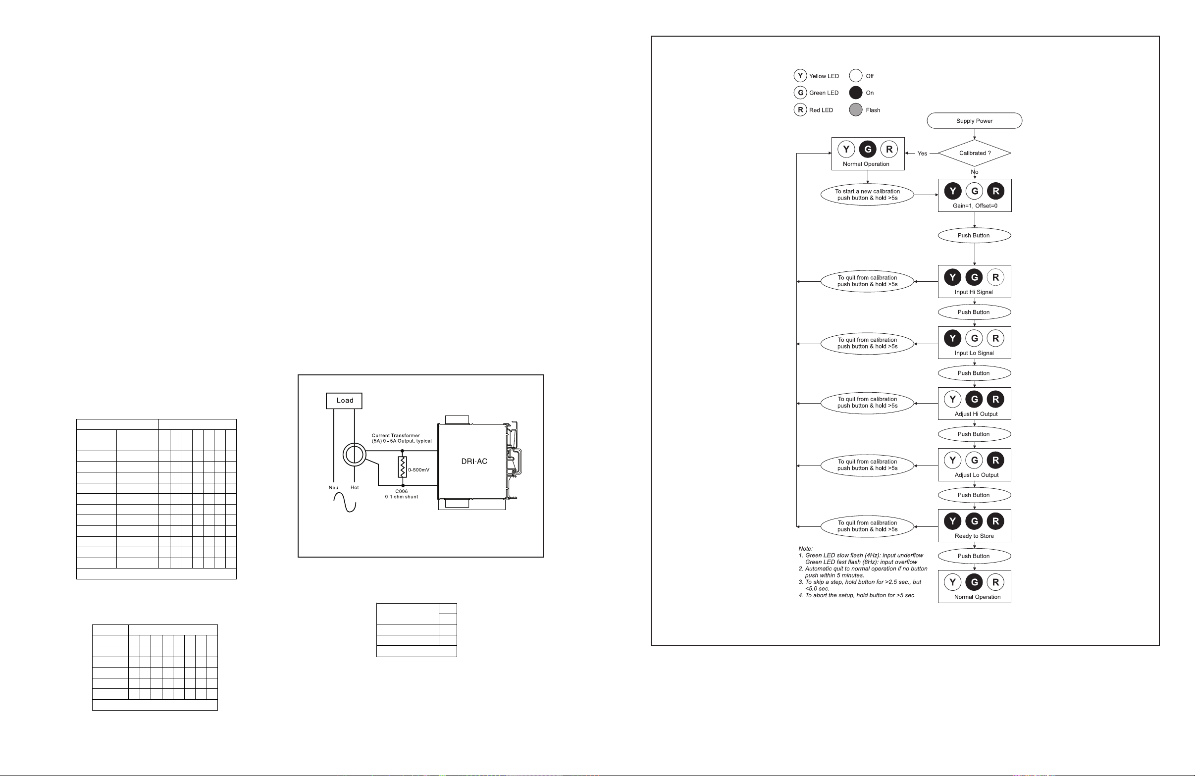
holditdownformorethan5seconds(untiltheyellowandGreen
LEDsareashing),thenreleasethebutton.
Note:Toquitthecalibrationmodeandresettheunit,pushand
holdtheCALbuttonformorethan5seconds.Or,waitformore
than two minutes and the unit will timeout and automatically
resettothepreviouslystoredcalibration.
4.WhentheyellowandgreenLEDsstopashing,theyellow
andredLEDswillbeon.PushtheCALbuttonmomentarily(the
yellowandgreenLEDswillnowbeon).
5. Apply the maximum input signal level desired and push the
CALbuttontostore.TheyellowLEDwillnowbeon.
6. Apply the minimum input signal level desired and push the
CALbuttontostore.ThegreenandredLEDwillnowbeon.
7. Adjust the input signal while monitoring the output signal until
the output is at the desired maximum level (e.g. 20.00mA), then
pushtheCALbuttontostore(theredLEDwillbeon).
8.Adjusttheinputsignalwhilemonitoringtheoutputsignaluntil
the output is at the desired minimum level (e.g. 4.00mA), then
pushthe CALbuttontostore(theyellow,greenandred LEDs
willbeon).
9.Tonishcalibration,pushtheCALbuttononceagain.The
greenLEDwillbeoniftheinputiswithinthecalibratedrange.
3.Adjusttheinputsignaltothedesiredmaximumandobserve
thatthegreenLEDisonorashing.PushtheCALbuttonand
Table1:InputRangeSettings
Ranges Selector SW1
AC Voltage AC Current 1 2 3 4 5 6 7
100mV 10mA
200mV 20mA
500mV 50mA
1V 100mA
2V
5V
10V
20V
50V
100V
200V
300V
Key: = 1 = ON or Closed
Table2:OutputRangeSettings
Ranges Selector SW2
Output 1 2 3 4 5 6 7 8
0 to 5V
0 to 10V
0 to 1mA
4 to 20mA
0 to 20mA
Key: = 1 = ON or Closed
Figure1:Loadmonitoringusingacurrent
transformerandtheDRI-AC
Table3:InputTypeSettings
Current
Voltage
SW1
8
Input Type
Key: = 1 = On or Closed
Specications
Inputs:
Voltage:
Ranges:100mVACto300VAC
Impedance: >100K ohms
Overvoltage:330VAC
Current:
Ranges:10mAAC to 100mAAC
Impedance: 20 ohms, typical
Figure2:DRI-ACCalibrationFlowChart
Overcurrent: 170mAAC
Overvoltage: 60V peak
FrequencyRange:
40Hzto400Hz,factorycalibratedat60Hz
CommonMode(InputtoGround):
1800VDC,max.
PushbuttonAdjustment:
Max.zerooffsetandspanturndownis50%
 Loading...