

Page 1
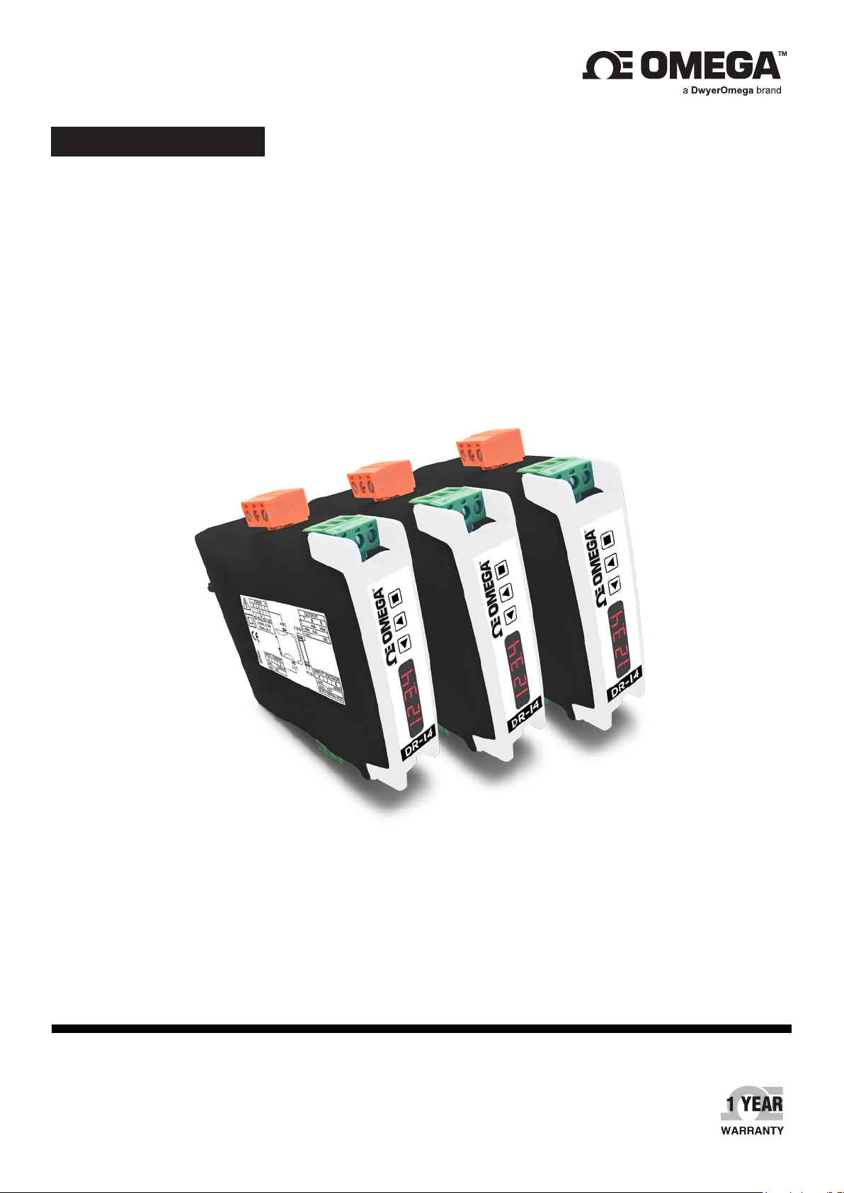
USER’S GUIDE
DR-I4F
Signal Converter for Impulses and Frequency
Signals, Isolated, for Industrial Applications
omega.com | [email protected]
For latest product manuals:
omega.com/en-us/pdf-manuals
TM
Page 2

CONTACT
Omega Engineering, Inc.
omega.com/contact-us
Toll-Free:
1-800-826-6342 (USA & Canada only)
Customer Service:
1-800-622-2378 (USA & Canada only)
Engineering Service:
1-800-872-9436 (USA & Canada only)
Telephone:
(203) 359-1660
Fax:
(203) 359-7700
Email: [email protected]
For other locations visit:
omega.com/worldwide
The information contained in this document is believed to be correct,
but Omega accepts no liability for any errors it contains, and reserves
the right to alter specifications without notice.
Page 3

Table of Contents
1. How to Order .......................................................................................................................................................................4
2. Material Included ................................................................................................................................................................4
3. Additional Information .......................................................................................................................................................4
4. Installation and Start-Up ..................................................................................................................................................4
5. Typical Applications ...........................................................................................................................................................5
6. SOS Mode .............................................................................................................................................................................5
7. Messages ..............................................................................................................................................................................5
8. Predefined Configuration Codes ....................................................................................................................................6
9. Predefined Sensors ............................................................................................................................................................7
10. Reading Channels ..............................................................................................................................................................7
11. Connections and Dimensions (mm (inch))) ................................................................................................................8
12. How to Operate the Instrument ......................................................................................................................................9
12.1. Configuration System ......................................................................................................................................................... 9
12.2. ‘Normal Mode’ of Operation ............................................................................................................................................ 9
12.3. How to Operate the Configuration Menu ...................................................................................................................10
12.4. How to Operate the ‘Force’ Menu ................................................................................................................................. 11
12.5. How to Activate the ‘Messages’ Function ................................................................................................................... 12
12.6. Fast and Advanced Configurations ..............................................................................................................................12
13. Input Signals ........................................................................................................................................................................12
13.1. Low Voltage Frequency Signals ..................................................................................................................................... 12
13.2. V AC Frequency Signals .................................................................................................................................................... 13
14. Technical Specifications ...................................................................................................................................................14
15. Frequency Calculation Modes ........................................................................................................................................16
16. Configuration Menu............................................................................................................................................................17
16.1. Function Codes and Sensor ............................................................................................................................................. 17
16.2. Sensor Configuration .......................................................................................................................................................... 18
16.3. Input Range ............................................................................................................................................................................ 19
16.4. Output Range ......................................................................................................................................................................... 20
16.5. Advanced Scaling ................................................................................................................................................................ 20
16.6. Display Information .............................................................................................................................................................21
16.7. Key ‘UP’ (‘Force’ menu) ..................................................................................................................................................... 21
16.8. Key ‘LE’ (‘Messages’ function) .........................................................................................................................................22
16.9. ‘Tools’ Menu ............................................................................................................................................................................ 23
17. Full Configuration Menu ...................................................................................................................................................25
18. Factory Default Parameters .............................................................................................................................................27
19. Error Codes and Messages .............................................................................................................................................28
20. Precautions on Installation ..............................................................................................................................................28
21. CE Declaration of Conformity.........................................................................................................................................29
Table of Contents 3
Page 4

Signal converter for impulses and frequency signals, isolated, for industrial applications
Isolated signal converter for frequency signals. Congurable to work with NPN, PNP, pick-up, Namur, mechanical
contact, reed contact and other types of sensors. Dedicated input to measure frequency from AC voltage signals
up to 600 V AC. Accepts a wide range of frequency ranges, from 1 Hz up to 1 MHz, with minimum workable signal
of 100 mHz and resolution of 1 mHz.
Congurable output in 4/20 mA (active or passive) or 0/10 V DC. Universal power supply from 18 to 265 V AC/
DC. 3 way isolation between input, output and power circuits. Circuit isolation prevents ground loops and transient
propagation, protecting remote equipment and signal integrity.
Predened conguration codes available for fast and easy conguration. Advanced conguration menu available
to customize input and output signal ranges to specic values required, and different sensor parameters.
Conguration through front push-button keypad. Front information displays for conguration and system
information (input signal value, output signal value, congured label, signal percentage and process value).
Built-in ‘force’ functions to manually generate low and high output signals, to validate remote instrumentation
during installation. ‘SOS’ mode to help on critical maintenance and repairs. Congurable power frequency
rejection lter. ‘Password’ function to block non-authorized access to ‘conguration menu’.
Designed for industrial use, with potential integration into a wide range of applications, reduced cost, excellent
quality and available customization.
1. How to Order
Reference Description
DR-I4F Signal converter for frequency signals
2. Material Included
The instrument is provided with the following elements:
• 1 x instrument DR-I4F
• 4 x plug-in screw terminals
• 1 x quick installation guide”
3. Additional Information
To view the DR-I4F spec sheet and manuals visit us at: https://www.omega.com/
4. Installation and Start-Up
Important: If this is the rst time you are conguring the instrument, below are the steps to follow during a rst
installation. Read all the manual sections in order to have a full and clear view of the characteristics of the
instrument. Do not forget to read the installation precautions at section 20.
Step 1: Install the instrument at the DIN rail
Step 2: Read how to operate the instrument (see section 12)
Step 3: Connect the input, the output and the power terminals (see section 11).
Step 4: Congure the sensor
• choose one of the predened sensors (see section 9)
• congure the sensor at the instrument (see section 16.1)
Step 5: Congure the input and output signals
• choose a predened conguration code (see section 8)
• introduce the code at the instrument (see section 16.1)
Step 6: If needed, customize the input and output signal ranges (see section 16.5)
Step 7: If needed, congure the display reading (see section 16.6), the key ‘UP’ () ‘force’ menu (see section 16.7),
and the key ‘LE’ () ‘messages’ function (see section 16.8),
Step 8: If needed, block access to the ‘conguration menu’ (see section 16.9)
4 DR-I4F User's Manual
Page 5
5. Typical Applications
To measure frequency signals from low voltage sensors such as NPN, PNP, Namur, pick-up and similar. To
measure frequency signals from ow meters. To measure frequency signals from AC power networks up to 600
V AC. Signal acquisition, linearization and transmission to remote acquisition devices. Isolation between circuits
provided. Ranges can be scaled to the desired range.
6. SOS Mode
The instrument includes a congurable ‘SOS mode’ function that provides a way to manually congure a xed
output signal. This output signal remains xed, independent of the input signal value or sensor state.
This function allows to perform urgent maintenance or repair tasks at the input section of the system, for example
replacing sensors, shunts, or deactivating power lines, while the instrument still provides a controlled signal that
allows for the process to continue its activity, under human surveillance. When the maintenance or repair task
has been performed, the instrument can be taken back to the standard working mode, where the output signal is
proportional to the input.
When manually activated, the ‘SOS mode’ generates the output signal congured, and the front display remains
ashing with the message ‘SoS’. All other systems are disabled, which means that :
• no error messages will be shown on display
• no key ‘UP’ () ‘fast access’ menu is accessible
• no key ‘LE’ () ‘messages’ function is accessible
• no ‘Eco’ mode activates
Only key ‘SQ’ () is accessible, to access the ‘conguration menu’ (eventually this access can be password
locked) in order to deactivate the ‘SOS mode’. Deactivation of ‘SOS mode’ must be performed manually by
conguring the function to ‘oFF’.
To congure the ‘SOS mode’ function, see section 16.9.
7. Messages
The instrument includes a congurable ‘messages’ function that provides advanced system information on the
display, available to the operator with a single click at the front key ‘LE’ ().
This information is helpful during start-up, installation, system verication, routine maintenance and troubleshooting,
as messages and values provide information on the actual input and output signal value, actual percentage of the
input signal compared to the full scale and scaled process values.
This information is available at any time, and is displayed sequentially when requested. Access to this information
reduces maintenance time, improves time invested in failure location, and helps for an easy resolution of the
problem.
Additionally, each instrument can be assigned a custom label code of up to 8 characters (see Table 1), that can
be displayed at the front display or at the messages sequence, making system identication of each instrument
an easy task.
To congure the ‘messages’ function, see section 16.8.
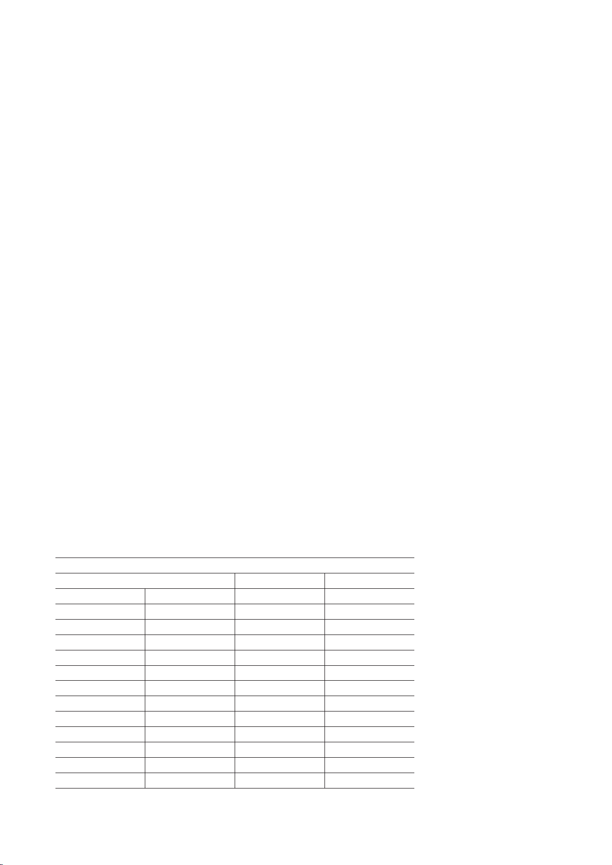
Table 1 | Available label codes (‘Label’ parameter)
Letters Numbers Special
A n 0 -
b o 1 _
c P 2 .
d q 3 (blank)
E r 4
F S 5
G t 6
h u 7
I V 8
J W 9
K X
L Y
M Z
Labeling examples (‘Label’ parameter): for an application with multiple engine control, where RPM is being
measured for three engines, and converted to 4/20 mA for retransmission to PLC or SCADA. Three DR-I4F
5Typical Applications
Page 6

converters are being used, to measure 0/1000 Hz. Each DR-I4F can be congured the following label for easy
identication:
• Label for engine 1 frequency measurement : Eng1.hZ
• Label for engine 2 frequency measurement : Eng2.hZ
• Label for engine 3 frequency measurement : Eng3.hZ
8. Predefined Configuration Codes
Select the desired code for your application, and check the wing sections for more information:
• for information on how to activate a code, see section 16.1
• to customize the input and output signals, see section 16.5
Table 2 | Predened conguration codes - Input / Output
Input Signal Range
0/1 Hz 010 110
0/2 Hz 011 111
0/4 Hz 012 112
0/6 Hz 013 113
0/8 Hz 014 114
0/10 Hz 015 115
0/20 Hz 016 116
0/40 Hz 017 117
0/60 Hz 018 118
0/80 Hz 019 119
0/100 Hz 020 120
0/200 Hz 021 121
0/400 Hz 022 122
0/600 Hz 023 123
0/800 Hz 024 124
0/1 KHz 025 125
0/2 KHz 026 126
0/4 K Hz 027 127
0/6 KHz 028 128
0/8 KHz 029 129
0/10 KHz 030 130
0/20 KHz 031 131
0/40 K Hz 032 132
0/60 KHz 033 133
0/80 KHz 034 134
0/100 KHz 035 135
0/1 MHz 036 136
Reserved 037 to 099 137 to 199
(End of list) ‘---’ (see notes below)
(Custom selection) ‘uSEr’ (see notes below)
Output 4/20 mA
Code
Output 0/10 V DC
Code
Notes:
• Predened conguration codes do no affect the sensor conguration.
• Code ‘uSEr’ indicates that a user custom conguration is active, and it does not match any of the listed codes.
This code is non-selectable, for information only.
Example: select code ‘025’ for 0/100 Hz=4/20 mA, the instrument reads code ‘025’. Later, congure the input to
0/950 Hz = 4/20 mA, this does not match a listed code, and the instrument reads ‘uSEr’. Or change the output to
0/100 Hz = 1/5 V DC, this does not match a listed code, and the instrument reads ‘uSEr’.
• Code ‘---’ identies the end of the list, it follows code ‘199’ and the list with code ‘010’. Select ‘---’ exits the
‘conguration menu’ without applying changes.
6 DR-I4F User's Manual
Page 7

9. Predefined Sensors
Select the desired sensor for your application and check the following sections for more information:
• for information on how to select a predened sensor, see section 16.1
• to customize the sensor conguration, see section 16.2
Table 3 | Predened sensors and associated conguration
Sensor
NPN pull-up x1 25 0 mS +15 V B 100 KHz
PNP pull-down x1 15 0 mS +15 V B 10 0 KHz
Mechanical pull-up x1 25 100 mS +15 V B 500 Hz
Reed pull-up x1 25 100 mS +15 V B 500 Hz
Pick-up none x100 15 0 mS +15 V A 50 KHz
Namur pull-down x1 15 0 mS +8.2 V B 1 MHz
TTL none x1 15 0 mS +5 V B 1 MHz
V AC none x1 15 0 mS Off A 1 KHz
Pull
resistors
Gain
Trigger
level
Anti
rebound
Vexc
Reading
channel
Max.
Frequency
10. Reading Channels
Reading channels ‘A’ and ‘B’ have different frequency bandwidths and different detection levels. Each ‘Predened
sensor’ has a channel, assigned by default, although the channel can also be manually congured (see section
16.2). Below are the characteristics of each channel.
Channel ‘A’
• has a ‘zero crossing’ type of detection
• has a bandwidth limit of 80 KHz (with gain ‘x1’) and 30 KHz (with gain ‘x100’). Maximum frequencies for each
type of sensor are listed at ‘Table 3’.
• has a congurable gain of ‘x1’ or ‘x100’, available to signals connected at terminals ‘1, 2, 3’. Use the ‘x100’
gain to work with pick-up signals with at least 10 mVpp.
Channel ‘B’
• has signal detection levels at approximately ‘<1 V’ and ‘>2 V’, which provides a higher noise immunity when
compared to channel ‘A’.
• has a bandwidth limit of 1 MHz.
• is the default channel for all sensors, except V AC and pick-up.
7Predened Sensors
Page 8
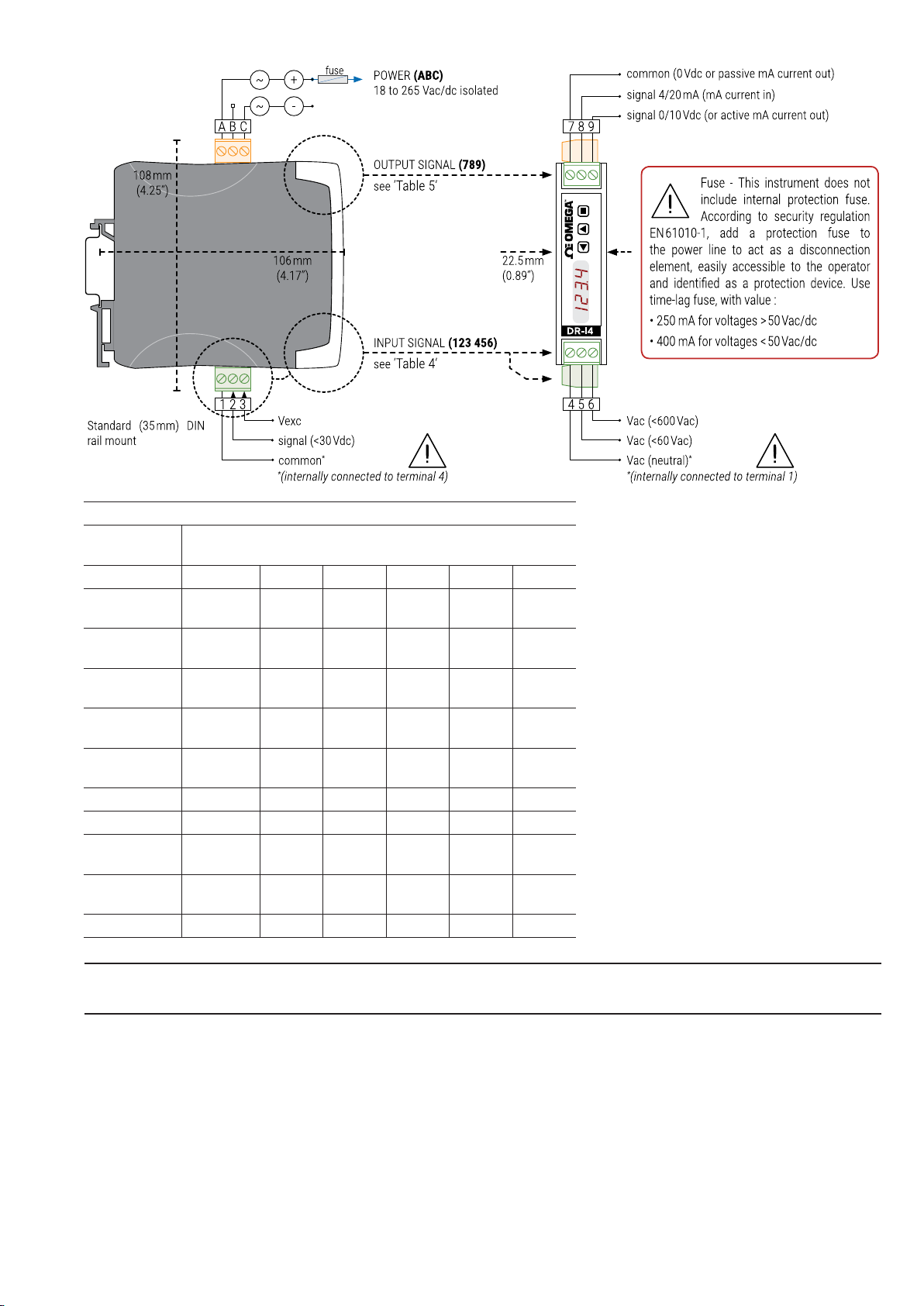
11. Connections and Dimensions (mm (inch)))
Table 4 | INPUT signal connections
INPUT
signal
1 2 3 4 5 6
V AC
(<600 V AC)
V AC
(<60 V AC)
NPN
(2 wires)
PNP
(2 wires)
NPN, PNP
(3 wires)
Pick-up common signal
Namur signal Vexc
Mechanical
contact
Reed
contact
Others common signal Vexc
common signal
signal Vexc
common signal Vexc
common signal
common signal
Input terminals
~V AC ~V AC
~V AC ~V AC
Caution: Terminal 4 and terminal 1 are internally connected. Connecting dangerous voltages to terminal 4 makes
terminal 1 a terminal with dangerous voltage.
8 DR-I4F User's Manual
Page 9
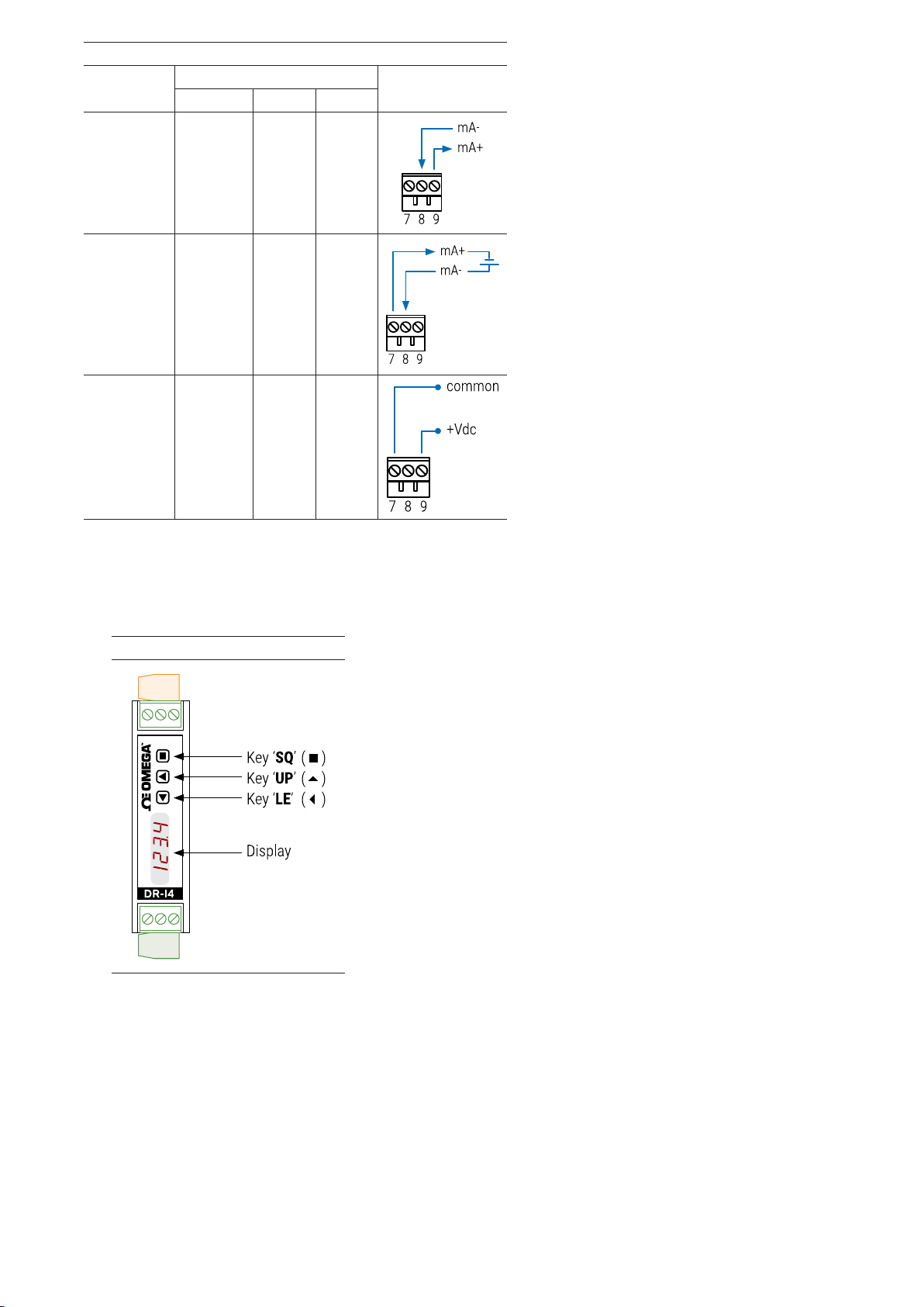
Table 5 | Output Signal Connections
OUTPUT
signal
Output terminals
7 8 9
Connections
4/20 mA
active
output
4/20 mA
passive
output*
(*external
loop power
needed)
0/10 V DC common +V DC
mA+
(out)
mA-
(in)
mA-
(in)
12. How to Operate the Instrument
12.1. Configuration System
The instrument is fully congurable from the 3 push button keypad a the 4 red digit led display at the front of
the instrument (see Table 6).
mA+
(out)
Table 6 | Conguration System
12.2. ‘Normal Mode’ of Operation
AT POWER-UP
When the power supply is connected, the instrument applies the following sequence :
• the ‘display’ shows the rmware code ‘b4.xx’.
• the ‘display’ shows the congured ‘sensor’, ‘input range’ and ‘units’, (for example: ‘SEnSor nPn’, ‘1.000’ and
‘KHz’).
• the instrument is now in ‘normal mode’ of operation and the ‘display’ shows the ‘information’ congured
at section 16.6.
FROM ‘NORMAL MODE’ OF OPERATION
From ‘normal mode’ of operation, the operator can access the following functions:
• key ‘SQ’ () gives access to the ‘conguration menu’ (see section 12.3).
• key ‘UP’ () gives access to the ‘force’ menu (see section 12.4).
9How to Operate the Instrument
Page 10
• key ‘LE’ () activates the ‘messages’ function (see section 12.5).
‘ECO’ FUNCTION (‘DISPLAY’ POWERED OFF)
The ‘Eco’ function powers off the display under the following conditions:
• the instrument is in ‘normal mode’ of operation.
• there is no interaction from the operator for 60 seconds.
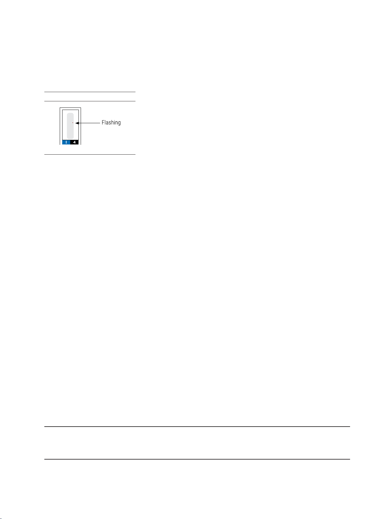
The decimal point remains active (ashing), indicating that the instrument is working correctly. This is a
congurable function, enabled by default. To congure the ‘Eco’ function, see section 16.9.
Table 7 | ‘ECO’ Decimal Point
12.3. How to Operate the Configuration Menu
HOW TO ENTER THE ‘CONFIGURATION MENU’
With the instrument in ‘normal mode’ of operation (see section 12.2), press the ‘SQ’ () key and maintain for 1
second. The horizontal LEDs light from bottom to top. When the upper led lights, the instrument enters into the
‘conguration menu’.
When entering the ‘conguration menu’, the rst menu entry ‘Function code’ (codE) is displayed. See section
17 for a full view of the ‘conguration menu’.
If the ‘SQ’ () key is released before entering into the ‘conguration menu’, the horizontal LEDs light
downwards from top to bottom, and the instrument returns to ‘normal mode’ of operation.
HOW TO OPERATE INSIDE THE ‘CONFIGURATION MENU’
Inside the ‘conguration menu’, use the front keypad to move through menu entries, parameters, and select
conguration values:
• Key ‘SQ’ () functions as the ‘ENTER’ key. It selects the menu entry currently displayed. At numerical value
entries, it validates the number displayed.
• Key ‘UP’ () moves vertically through the different menu entries. At numerical value entries, it modies the
selected digit by increasing its value to 0, 1, 2, 3, 4, 5, 6, 7, 8, 9. The most signicant digit has additional values
‘-’ and ‘-1’.
• Key ‘LE’ () functions as the ‘ESCAPE’ key. It leaves the selected menu entry, and eventually, will leave
the ‘conguration menu’. When leaving the ‘conguration menu’, the changed parameters are activated. At
numerical value entries, the ‘LE’ () key allows to select the active digit. To modify a numeric value press the
‘UP’ () key to increase the value ‘+1’. Press the ‘SQ’ () key to validate the value.
WHEN EXITING THE ‘CONFIGURATION MENU’
When exiting the ‘conguration menu’ without changes (either by ‘rollback’ activation or because there are no
changes in the conguration), the horizontal LEDs light down from top to bottom, and the instrument returns to
‘normal mode’ of operation.
When exiting the ‘conguration menu’ with changes, the display LEDs light a round shape while the new
conguration is stored. When the round shape is nished, a start-up is applied (see section 12.2). After startup, the new conguration is active and the instrument is in ‘normal mode’ of operation.
‘ROLLBACK’ FUNCTION
If there is no interaction from the operator for 60 seconds, the instrument exits the ‘conguration menu’
discarding changes, and returns to ‘normal mode’ of operation.
Important: When the operator is inside the ‘conguration menu’, the output signal will remain overranged at
maximum signal. Additional congurations are available at the ‘On ‘Sq’’ parameter (see section 16.9).
When the operator exits the ‘conguration menu’, the output signal is temporarily set to minimum value for a
time <5 seconds, while the instrument restarts.
10 DR-I4F User's Manual
Page 11
12.4. How to Operate the ‘Force’ Menu
HOW TO ENTER THE ‘FORCE’ MENU
With the instrument in ‘normal mode’ of operation (see section 12.2), press and hold the ‘UP’ () key for 1
second. The horizontal LEDs light from bottom to top. When the upper led lights, the instrument enters into the
‘force’ menu.
If the ‘UP’ () key is released before entering into the ‘force’ menu, the horizontal LEDs light downwards from
top to bottom, and the instrument returns to ‘normal mode’ of operation.
HOW TO OPERATE INSIDE THE ‘FORCE’ MENU
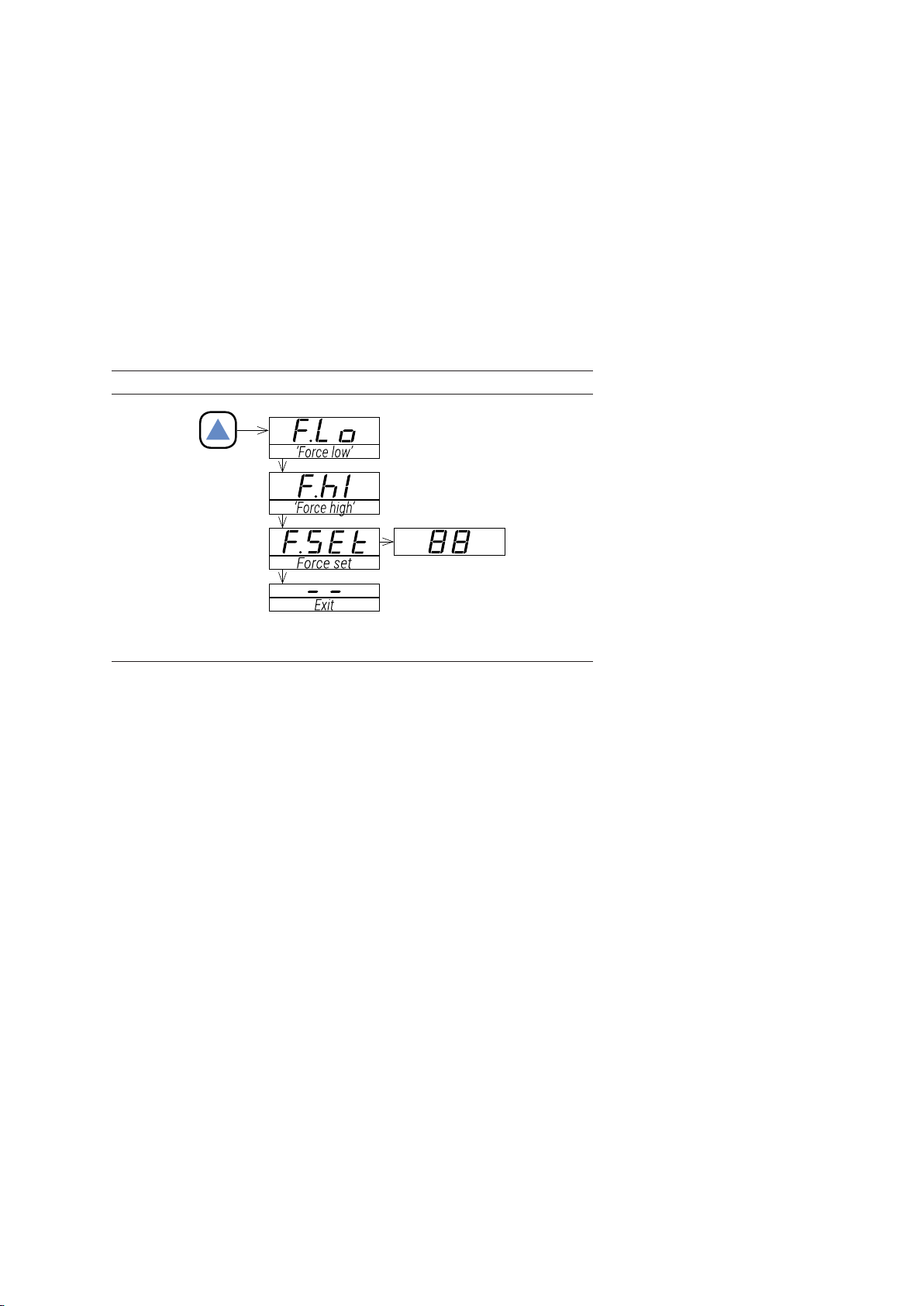
The available functions inside the ‘force’ menu can be congured (see section 16.7). By default, ‘Force high’,
‘Force low’ and ‘Force set’ are available. Inside the ‘force’ menu:
• press the ‘UP’ () key to move to the next function.
• press the ‘SQ’ () key to activate the selected function.
When the function is active, the display will remain ashing. Press the ‘SQ’ () key to deactivate the function
(display stops ashing), or wait for the rollback to activate.
Table 8 | Example of ‘Force’ menu with all functions set to ‘on’
See section 16.7 for a list and a description of available functions
DESCRIPTION OF ‘FORCE’ FUNCTIONS
The ‘force’ functions allow to manually force the output signal to the low and high levels of the output signal
selected. These functions allow to easily validate the correct function of remote elements connected to the
instrument output, such as PLC, HMI’s, SCADAs, etc.
The ‘force low’ function sets the output signal to the minimum value of the selected range (4 mA or 0 V DC or
the value congured at the ‘output_ low’ parameter).
The ‘force high’ function sets the output signal to the maximum value of the selected range (20 mA or 10 V DC
or the value congured at the ‘output_high’ parameter).
The ‘force set’ function sets the output signal to a value between 0 and 100% of the maximum selected range
(4 to 20 mA or 0 to 10 V DC or the range congured at the ‘output_low’ and ‘output_high’ parameters). When
entering the ‘force set’ function, the display reads ‘50’ (the output is forced to 50% of the congured range).
Use keys ‘UP’ () and ‘LE’ () to move up to 100% or down to 0% of the congured range.
HOW TO EXIT ‘FORCE’ MENU
To exit the ‘force’ menu, press the ‘LE’ () key, or press the key ‘UP’ () key until the parameter ‘---’ appears,
and select by pressing the ‘SQ’ () key, or wait without pressing any key until the automatic ‘rollback’
activates.
When exiting the ‘force’ menu, the horizontal LEDs light down from top to bottom, and the instrument returns to
‘normal mode’ of operation.
‘ROLLBACK’ FUNCTION
If there is no interaction from the operator for 60 seconds, the instrument exits the ‘force’ menu and returns to
‘normal mode’ of operation.”
11How to Operate the Instrument
Page 12

12.5. How to Activate the ‘Messages’ Function
HOW TO ACTIVATE ‘MESSAGES’ FUNCTION
With the instrument in ‘normal mode’ of operation (see section 12.2), press the ‘LE’ () key to activate
the ‘messages’ function. The ‘messages’ function displays information about the instrument. The
information available is congurable (see section 16.8).
The ‘messages’ function ends when all the information has been displayed or front keys ‘UP’ () or ‘SQ’ ()
are pressed. The ‘display’ returns to ‘normal mode’ of operation.
12.6. Fast and Advanced Configurations
FAST CONFIGURATION
The fastest way to congure the instrument is to activate one of the predened conguration codes (see
section 8) and predened sensors (see section 9).
Access the ‘conguration menu’ and enter the ‘Function code’ (codE) menu entry. The code displayed is the
current active input - output range. Select the new code and validate. Selecting a code automat exits the
‘conguration menu’ and activates the new conguration.
Important: There are different codes for 4/20 mA and 0/10 V DC output signals.
Access the ‘conguration menu’ and enter the ‘Predened sensors’ (SnSr) menu entry. The sensor displays the
actual congured sensor. Select the desired sensor and validate.
To customize the input and output signals, see the ‘Advanced scaling’ section of the ‘conguration menu’ (see
section 16.5).
To customize the sensor parameters, see the ‘Sensor conguration’ section of the ‘conguration menu’ (see
section 16.2).
ADVANCED CONFIGURATION
Additional conguration parameters are available at the ‘conguration menu’. The operator can customize the
input and output signal ranges, sensor parameters, the message seen on display, the functions available at
the ‘force’ menu, the messages associated to the ‘LE’ () key, activate lters, password function, etc.
See section 16 for a detailed explanation on the ‘conguration menu’.”
13. Input Signals
13.1. Low Voltage Frequency Signals
SIGNALS ACCEPTED
The instrument can be congured to measure frequency from typical impulse sensors, such as NPN, PNP,
pick-up, push-pull, mechanical contact, reed contact, Namur and similar.
The instrument parameters allow to congure pull-up and pull-down resistors, apply signal amplication for
very low voltage signal, modify the trigger level, apply anti-rebound lters, and congure the voltage to power
the sensor.
Although there is a dedicated menu entry for most popular sensor types, the operator can manually congure
the mentioned parameters as needed, as explained in section ‘16.2’.
PREDEFINED CONFIGURATION CODES
See ‘Table 2’ for a list of predened conguration codes for input-output signal ranges. To activate a code see
section 16.1.
CUSTOMIZED SIGNAL RANGES
To customize the input and / or output signal ranges, access the ‘Advanced scaling’ menu (see section 16.5).
ACCURACY AND FREQUENCY LIMITS
Accuracy depends on the calculation mode (see section 15). Maximum frequency depends on the sensor (see
Table 3).
TRIGGER LEVELS
When directed through reading channel ‘B’ (see section 10), a typical value for level detection is ‘0’ below 1 V
DC, and ‘1’ above 2 V DC. Operate the ‘Trigger level’ parameter (see section 16.2) to empirically move up and
down the trigger levels. The limit trigger level are approximately 0.5 V DC and 3 V DC.
Pick-up signals are typically channeled through channel ‘A’ and signal is detected as a ‘0 crossing.’ Trigger
levels can help improve noise immunity.
12 DR-I4F User's Manual
Page 13

13.2. V AC Frequency Signals
SIGNALS ACCEPTED
The instrument has a dedicated input to read frequency from voltages up to 600 V AC and voltages up to 60
V AC. Phase-to-phase and phase-to-neutral connections are accepted.
PREDEFINED CONFIGURATION CODES
See ‘Table 2’ for a list of predened conguration codes for input-output signal ranges. To activate a code see
section 16.1.
CUSTOMIZED SIGNAL RANGES
To customize the input and / or output signal ranges, access the ‘Advanced scaling’ menu (see section 16.5).
ACCURACY AND MAXIMUM FREQUENCY
Accuracy depends on the calculation mode (see section 15). Maximum frequency depends on the sensor (see
Table 3).
TRIGGER LEVELS
AC signals are channeled through channel ‘A’ and signal is detected as a ‘0 crossing’. Trigger levels can help
improve noise immunity around ‘0’.
MINIMUM AMPLITUDE LEVELS
The minimum voltage levels recommended are 30 V AC for the 600 V AC range, and 6 V AC for the 60 V AC
range. Signals with amplitude levels below 6 V AC, should be channeled as ‘low voltage’ input signals (see
section 13.1).
Table 9 | Connection Examples for V AC <600 V AC and < 60 V AC Signals
Important: Terminal 4 and terminal 1 are internally connected. Connecting dangerous voltages to terminal 4
makes terminal 1 a terminal with dangerous voltage.
Table 10 | Connection Examples
13Input Signals
Page 14
14. Technical Specifications
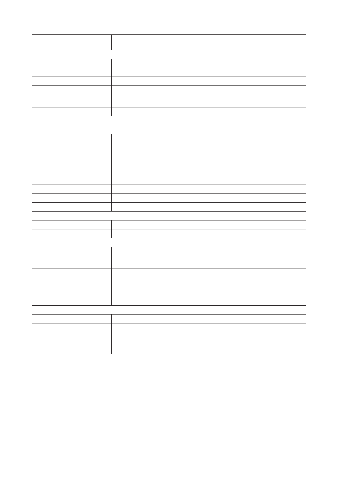
SENSORS
types of sensor
see the ‘Advanced sensor’ menu (see section 16.2) for sensor conguration
max. voltage at terminals (see Table 3)
input impedance (see Table 11)
maximum frequency (see Table 11)
excitation voltage
typical detection levels (see Table 3)
detection levels are changeable through the ‘trigger’ parameter
ACCURACY AT 25ºC
‘slow’ mode error f2 x 0.5 x 10-6 Hz.
‘fast’ mode error
quartz accuracy ±50 ppm
mA output accuracy 0.05 % FS
V DC output accuracy 0.10 % FS
thermal drift 50 ppm/ºC
min. detectable frequency 100 mHz (signals below 100 mHz are considered 0 Hz)
resolution 1 mHz
STEP RESPONSE
in ‘fast’ mode ‘Gate’ parameter + 50 mSec.
in ‘slow’ mode 1/frequency + 50 mSec.
OUTPUT SIGNAL RANGES
active current output
passive current output
voltage output
CONFIGURATION SYSTEM
key pad + display accessible at the front of the instrument
conguration ‘conguration menu’ and predened ‘codes’
scalable units
NPN, PNP, pick-up, push-pull, mechanical contact, reed contact, V AC,
...
15 V DC @50 mA
8.2 V DC @50 mA
5 V DC @50 mA
1/gate (see ‘gate’ parameter at section 16.2) (typical error 2 Hz for
‘gate’ of 0.5 seconds)
4/20 mA active
max. <22 mA, min. 0 mA
maximum load <400 Ohm
4/20 mA passive
max. 30 V DC on terminals
0/10 V DC,
max. <11 V DC, min. -0.05 V DC (typ.)
minimum load > 10 KOhm
scalable input ranges
scalable output ranges
scalable process display
14 DR-I4F User's Manual
Page 15

Table 11 | Sensor types and specications
Sensor Zin Max. voltage at terminals Minimum detectable signal / detection levels
NPN 5.1 KOhms ±30 V DC ‘0’ level <1 V, ‘1’ level >2 V
PNP 5.1 KOhms ±30 V DC ‘0’ level <1 V, ‘1’ level >2 V
Mechanical 5.1 KOhms ±30 V DC ‘0’ level <1 V, ‘1’ level >2 V
Reed 5.1 KOhms ±30 V DC ‘0’ level <1 V, ‘1’ level >2 V
Pick-up 100 KOhms ±30 V DC >10 mVp p
Namur 5.1 KOhms ±30 V DC ---
TTL 5.1 KOhms ±30 V DC ‘0’ level <1 V, ‘1’ level >2 V
<600 V AC 900 KOhms 800 V AC ---
<60 V AC 340 KOhms 200 V AC ---
POWER SUPPLY
voltage range 18 to 265 V AC/DC isolated
(20 to 240 V AC/DC ±10 %)
AC frequency 45 to 65 Hz
consumption <3.5 W
power wires 1 mm2 to 2.5 mm2 ( AWG17 to AWG14)
overvoltage category 2
ISOLATION
input - output 3000 Veff (60 seconds)
power - input 3000 Veff (60 seconds)
power - output 3000 Veff (60 seconds)
ENVIRONMENTAL
IP protection IP30
impact protection IK06
operation temperature from 0 to +50 ºC
storage temperature from -20 to +70 ºC
‘warm-up’ time 15 minutes
humidity 0 to 95 % non-condensing
altitude up to 2000 meters
MECHANICAL
size 106 x 108 x 22.5 mm
mounting standard DIN rail (35 x 7.5 mm)
connections plug-in screw terminal (pitch 5.08 mm)
housing material polyamide V0
weight <150 grams
packaging 120 x 115 x 30 mm, cardboard
15Technical Specications
Page 16

15. Frequency Calculation Modes
The instrument calculates the frequency applying the ‘slow’ mode or the ‘fast’ mode.
Fast mode
‘Fast’ mode activates when the ‘input high signal’ parameter (see section 16.5) is higher or equal than 500 Hz.
The frequency calculated is the number of impulses received during a time window, divided by the time window
value in seconds. The time window is congured at the ‘Gate’ (GAtE) parameter (see section 16.2) with available
values ‘0.5’, ‘1.0’, ‘2.0 and ‘4.0’ seconds.
The frequency value is calculated at the end of each time window.
Slow mode
‘Slow’ mode activates when the ‘input high signal’ parameter is below 500 Hz.
The frequency calculated is the inverse of the time between impulses. The value is calculated and updated every
time an impulse is detected.
Measured frequency is ‘0’ when the time between impulses is higher than the value congured at the ‘time_to_0’
(tt0) parameter (values between ‘1.0’ and ‘10.0’ seconds). Once the reading has dropped to ‘0 ’, the instrument
needs 2 impulses to measure a new frequency.
Ranges below 500 Hz can also be manually set to ‘fast’ mode if needed (see section 16.2). Parameters not
available in the active mode ill show ‘-nA-’ when accessing their value at the conguration menu.
16 DR-I4F User's Manual
Page 17
16. Configuration Menu
16.1. Function Codes and Sensor
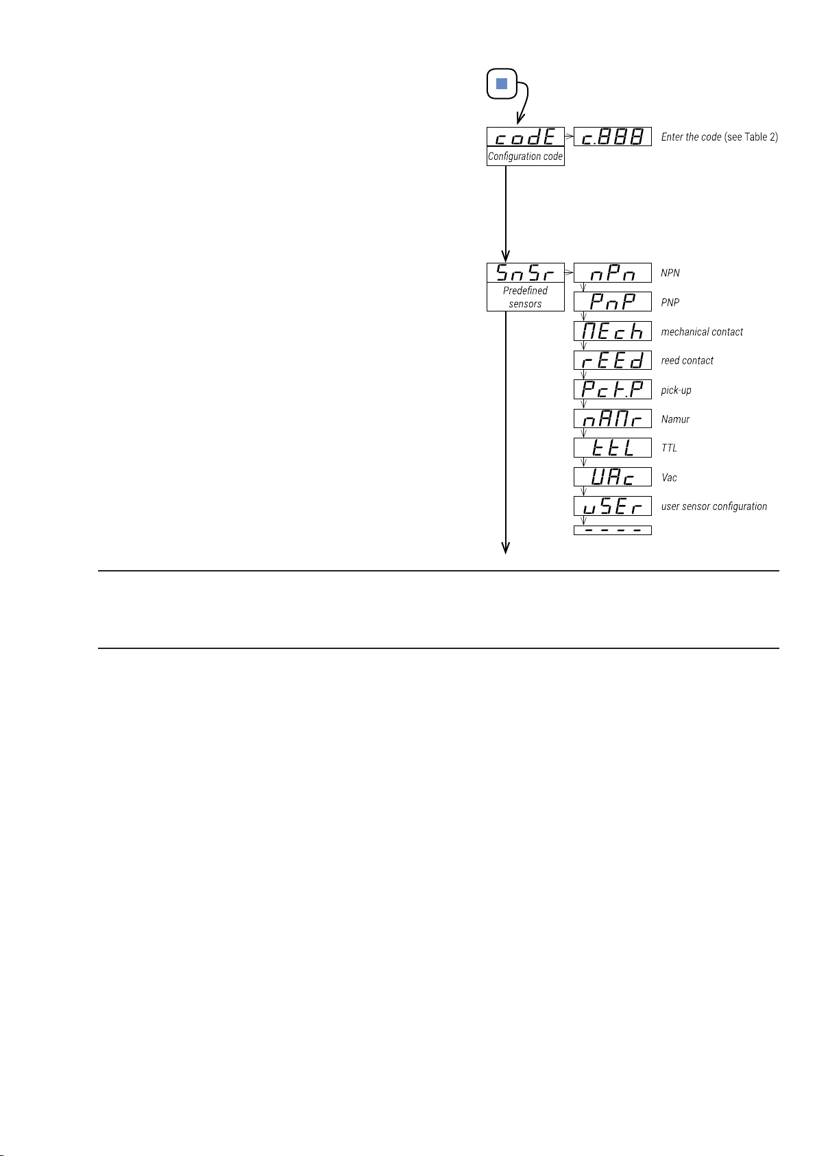
The fastest way to congure the instrument, is to select a
predened conguration code (see Table 2) and a predened
sensor (see Table 3). At the ‘Conguration code’ (codE)
parameter use keys ‘UP’ () and ‘LE’ () to move up and
down through the list of codes. Locate the desired code, and
press ‘SQ’ (). The instrument shows the ‘codE’ parameter.
Press ‘LE’ () to exit the ‘conguration menu’. The instrument
stores the new conguration, applies a ‘power-up’ routine and
returns to the ‘normal mode’ of operation (see section 12.2).
Selecting a ‘reserved’ code performs no action. Selecting ‘---’
exits the ‘conguration menu’ without applying changes.
When checking the ‘Function code’ (codE) parameter,
the active ‘conguration code’ is displayed. If the actual
conguration does not match any of the conguration codes,
code ‘uSEr’ is displayed.
There are different codes for 4/20 mA output (codes from 010
to 099) and 0/10 V DC output (codes from 110 to 199) (see
section 8).
To customize the input signal range, see the ‘Advanced
scaling’ section of the ‘conguration menu’ (see section 16.5).
At the ‘Predened sensors’ (SnSr) menu, select one of the
predened sensors. Once the sensor is congured, the
instrument is ready to work. The selection congures the
sensor according to ‘Table 3’ (see section 14) and updates
the parameters at the ‘Advanced sensor conguration’ (Ad.
Sn) menu. The actual sensor is displayed, and when the actual
conguration does not match any of the predened sensors,
then ‘uSEr’ is displayed.
Important: If the output signal is xed to 4 mA or 0 V DC, and does not change according to the frequency at
the input, then the input frequency detected is 0 Hz, and probably the predened sensor conguration is not
suitable for your sensor. A manual conguration of the sensor may be needed. See section 16.2 on how to
manually congure the sensor parameters.
17Conguration Menu
Page 18
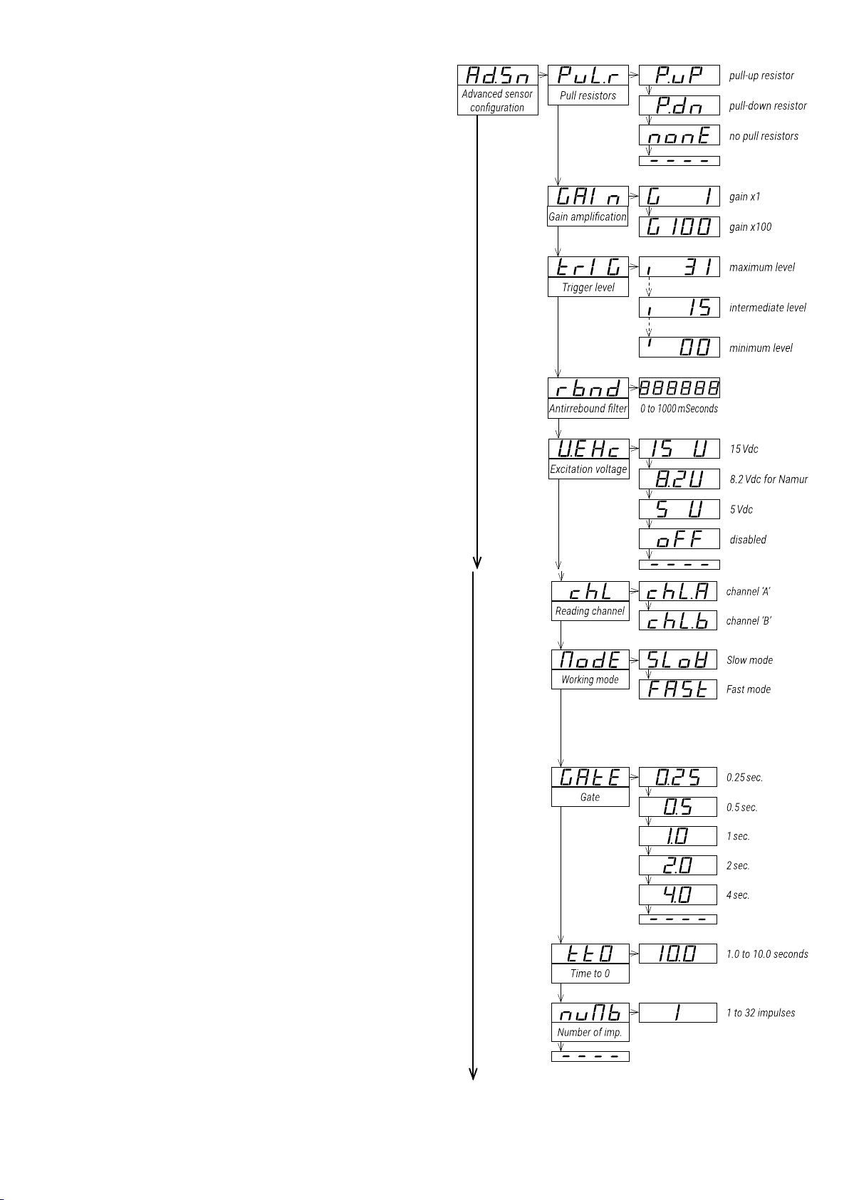
16.2. Sensor Configuration
Sensor conguration is a critical part of the
conguration. If the sensor is correctly congured,
the instrument will be able to read impulses. If the
sensor is not correctly congured, the instrument will
not be able to read any impulse signal and it will be
considered a 0 Hz signal.
• Parameters at the ‘Advanced sensor conguration’
(Ad.Sn), reect the conguration of the ‘Predened
sensors’ (SnSr) selection.
• Changing the parameters at the ‘Advanced
sensor conguration’ (Ad. Sn) menu, will set
the ‘Predened sensors’ (SnSr) value to ‘uSEr’
(‘User sensor conguration’) meaning that the
actual conguration does not match any of the
predened sensor congurations (see Table 3).
• At the ‘Pull resistors’ (PuL.r) parameter select the
activation or deactivation of pull-up and pulldown resistors.
• select ‘P.uP ’ to activate the pull-up resistor
• select ‘P.dn’ to activate the pull-down resistor
• select ‘nonE’ to deactivate the pull-up and pull down resistors
• At the ‘Gain amplication’ (GAIn) parameter select
the gain of the input signal . Gain applies only to
signals through channel ‘A’ and connected to
terminals ‘123’.
• select ‘G__1’ to activate the gain ‘1’. Usual
gain for V DC signals, that are correctly
detected operating the ‘trigger level’.
• select ‘G100’ to activate the gain ‘100’. Use this
gain for low voltage signals, in the range of mV,
that can not be detected by operating the
‘trigger level’ parameter to its lower value.
At the ‘Trigger level’ (trIG) parameter select empirically
the ‘trigger level’ at a level between ‘0’ and ‘31’. Default
value is ‘15’. Press key ‘UP’ () to increase the value, and
key ‘LE’ () to decrease the value.
• to help you identify the appropriate trigger level,
the vertical led at the left of the display is placed
at the bottom when the signal detected is ‘0’, and
is placed at the top when the signal detected is ‘1’.
Change the state of your input signal, and check
the status of the led to know if the instrument is
detecting the changes at the input.
At the ‘Antirrebound lter’ (rbnd) parameter select a
time value from ‘0’ to ‘1000’ expressed in milliseconds.
After a valid impulse has been detected, the detection
of new impulses is disables for the duration of the
congured time. Use this parameter to prevent detection
of rebounds. A ‘100’ milliseconds value is considered a
standard value to prevent rebounds when working with
mechanical contacts. Applies only in ‘slow mode’ (see
section 15).
At the ‘Excitation voltage’ (V.Exc) parameter select the
value of the excitation voltage. Select +15 V DC (15 V),
select +8.2 V DC (8.2V) for Namur sensors, select +5
V DC (5 V) for TTL or select oFF (oFF) to disable the
excitation voltage.
At the ‘Reading channel’ (chL) parameter select the
channel ‘A’ or ‘B’ to read the signal (see section 10).
At the ‘Working mode’ (ModE) parameter select the frequency calculation mode (see section 15).
18 DR-I4F User's Manual
Page 19
At the ‘Gate’ (GAtE) parameter congure the value to ‘0.25’, ‘0.50’, ‘ 1.0’, ‘2.0’ or ‘4.0’ seconds. Applies only in
‘fast’ mode (see section 15).
At the ‘Time to 0’ (tt0) parameter congure a value between ‘1.0’ and ‘10.0’ seconds. Applies only in ‘slow
mode’ (see section 15). Default value is 1 second.
At the ‘Number of imp.’ (nUMb) parameter congure a value between ‘1’ and ‘32’. Applies only in ‘slow mode’
(see section 15). Dene the number of impulses needed to calculate the frequency (default value ‘1’). ’ to wait
for 4 impulses, and then calculate the mean frequency value of the set of 4 impulses.
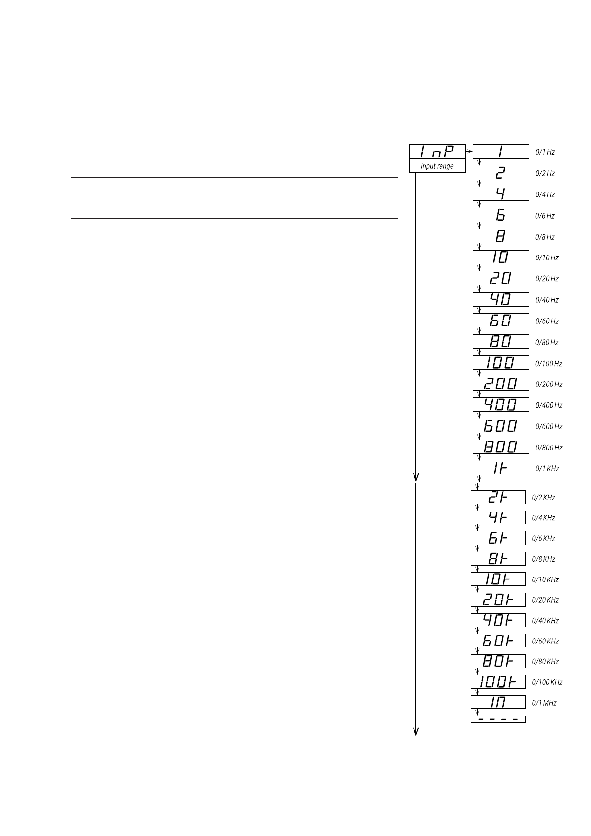
16.3. Input Range
At the ‘Input range’ (InP) menu entry select the input signal range to
activate.
Important: If you have already selected a conguration code (see section
16.1), the input range has been already selected and there is no need to
manually congure again at the ‘Input range’ (InP) menu entry.
Input signal ranges can also be activated through the ‘predened
conguration codes’ (see Table 2).
All input signal ranges can be congured to a reduced input signal range
by conguring the ‘Advanced scaling’ (Ad.Sc) parameters (see section 16.5).
• Example: select the ‘1 KHz ’ input range and to customize to a smaller
example 0/750 Hz or 250/750 Hz) see section 16.5 and operate each
parameter.
19Conguration Menu
Page 20
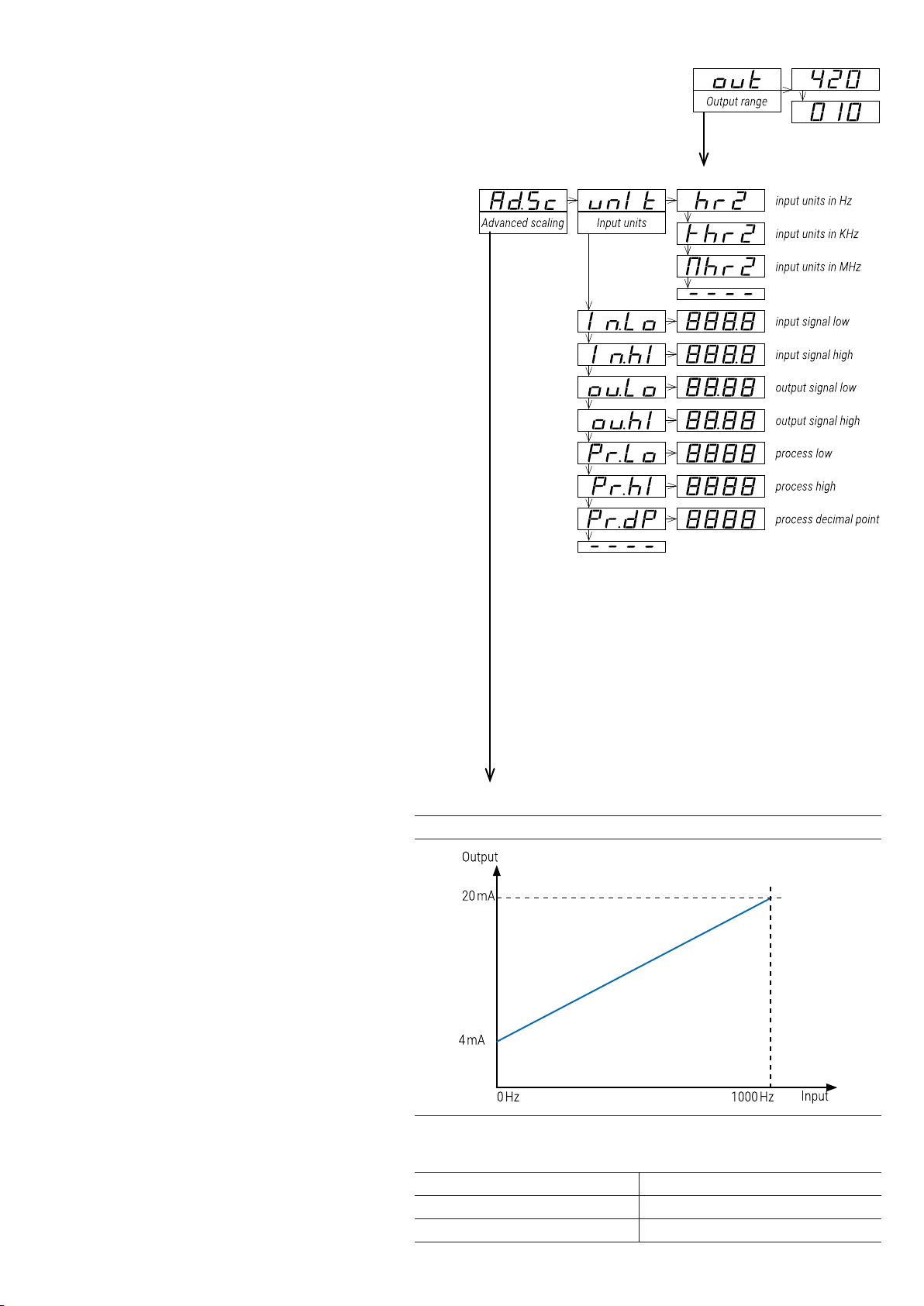
16.4. Output Range
At the ‘Output range’ (out) menu entry, select the output signal range to 4/20 mA
(value ‘420’) or to 0/10 V DC (value ‘010’).
The output signal range selected can be later customized to operate in a reduced
range of signal (see section 16.5).
16.5. Advanced Scaling
At the ‘Advanced scaling’ (Ad.Sc) menu, the input
and output signal ranges can be customized.
The parameters inside this menu represent the
real input and output signal ranges congured
at the instrument. When selecting a ‘predened
conguration code’, these parameters are
congured according to the code selected. The
parameters listed below, are accessible for
manual conguration:
• at the ‘Input units’ (unIt) parameter
congure the units for the input signal
parameters, between ‘Input units in Hz’
(hrZ), ‘Input units in KHz’ (KhrZ) and ‘Input
units in MHz’ (MhrZ).
• at the ‘Input low signal’ (In.Lo) parameter
congure the low input signal value. Units
expressed as congured at the ‘Input units’
(unIt) parameter, with 1 decimal point.
• at the ‘Input high signal’ (In.hI) parameter
congure the high input signal value. Units
expressed as congured at the ‘Input units’
(unIt) parameter, with 1 decimal point.
• at the ‘Output low signal’ (ou.Lo) parameter
congure the low output signal value. Units
expressed in V DC o mA, , with 2 decimal
points.
• at the ‘Output high signal’ (ou.hI) parameter
congure the high output signal value. Units
expressed in V DC o mA, , with 2 decimal
points.
These ve parameters dene the relation
between the input and the output signal (see
Table 12), and can be modied independently, to
match the specic input-output relation for your
application (see Table 12). Additionally, a process
value can be scaled using the last three
parameters of the ‘Advanced Scaling’ (Ad.
Sc) menu entry. The scaled process value
can be accessed through the ‘display
information’ function (see section 16.6) or
the ‘messages’ function (see section 16.8).
• at the ‘Process low’ (Pr.Lo) parameter,
congure the process value
associated to the low input signal
value.
• at the ‘Process high’ (Pr.hI) parameter,
congure the process value
associated to the high input signal
value.”
• at the ‘Process decimal point’ (Pr.
dP) parameter, congure the decimal
point position for the process value.
Example: a 0/1000 Hz signal from is
associated to a 0/150.0 RPM process
value. Congure the process value to ‘0’
and ‘150.0’ (‘Process low’ = ‘0’, ‘Process
high’=‘1500’, ‘Process decimal poin
process value in RPM can be displayed at
the front display.
Table 12 | Example for Code ‘025’ (0/1000 Hz = 4/20 mA
Selecting the predened code ‘025’ congures a range of
0/1000 Hz = 4/20 mA, and the values congured are as
indicated below:
input units = hertz (Hz)
input signal low = 0 Hz output signal low = 4.00 mA
input signal high = 1000 Hz output signal high = 20.00 mA
20 DR-I4F User's Manual
Page 21
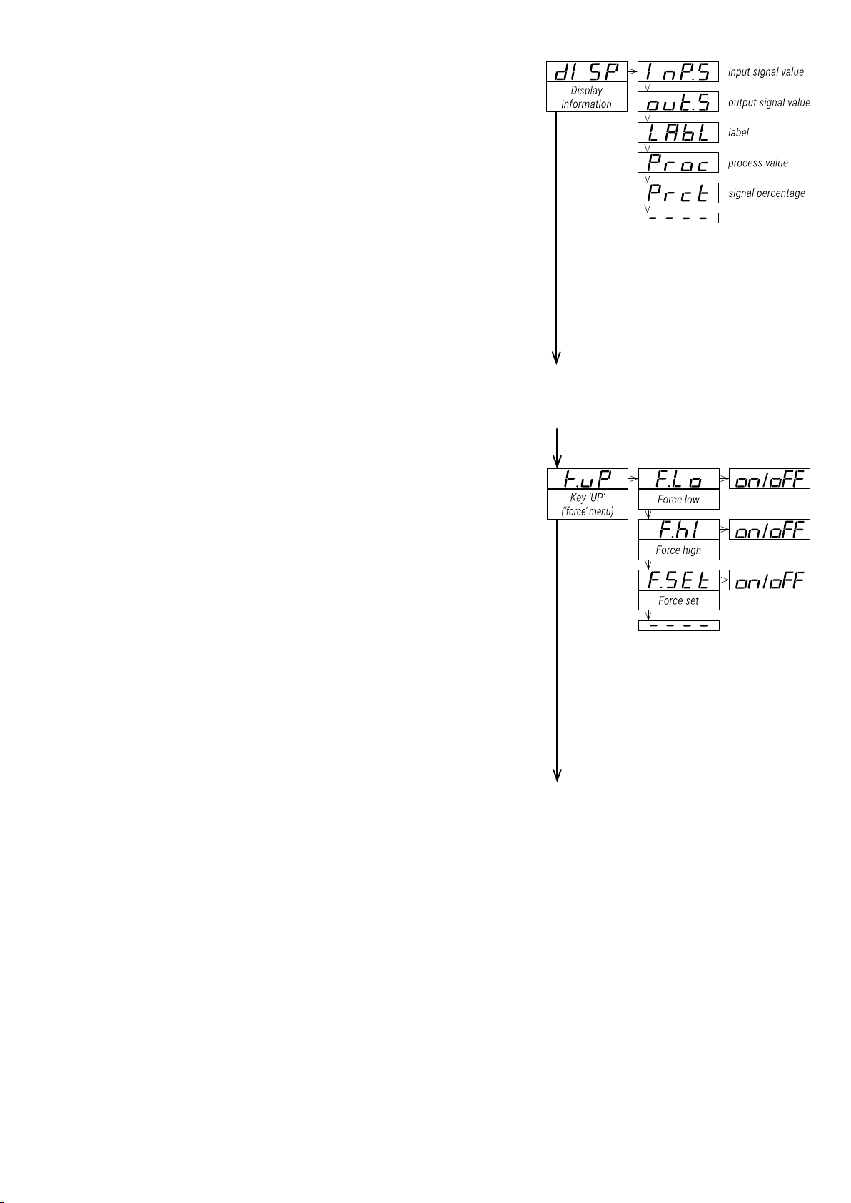
16.6. Display Information
At the ‘Display information’ (dISP) menu select one parameter
to read on display when the instrument is in ‘normal mode’ of
operation. If you need access to more than one information, see the
‘messages’ function (see section 16.8) associated to front key ‘LE’
().
• select ‘Input signal value’ (I nP. S ) to read the input signal value
and the measurement units (for example : ‘Inp hz 235’, ‘Inp Kh
235’, ‘Inp Mh 235’, ...).
• select ‘Output signal value’ (out.S) to read the output signal
value and the measurement units (for example : ‘Out mA
12.40’).
• select ‘Label’ (LAbL) to read the value congured at the ‘label’
parameter (see section 16.9).
• select ‘Process value’ (Proc) to read the process value as
scaled at the process parameters (see section 16.5) (for
example: ‘Proc 1500’).
• select ‘Percentage’ (Prct) to read the percentage of signal,
where ‘0’ is the value assigned to the ‘input signal low’
parameter, and ‘100’ is the value assigned to the ‘input signal
high’ parameter (see section 5) (for example : ‘Prct 23.5’ when the reading is 23.5% of the full scale).
16.7. Key ‘UP’ (‘Force’ menu)
The key ‘UP’ () at the front of the instrument gives access to a
congurable list of functions (see section 12.4).
At the ‘Key UP (‘force’ menu)’ (K.uP) menu select which functions
will be available when pressing the front key ‘UP’ (). Select ‘on’ to
activate the desired functions.
• congure ‘Force Low’ (F. Lo) to ‘on’ to activate the ‘Force low’
function menu entry.
• congure ‘Force High’ (F. hI) to ‘on’ to activate the ‘Force high’
function menu entry.
• congure ‘Force Set’ (F. S Et) to ‘on’ to activate the ‘Force set’
function menu entry.
The functions congured to ‘on’ are available at the ‘force’ menu.
See section 12.4 for a description on each function and how to
operate them.
21Conguration Menu
Page 22
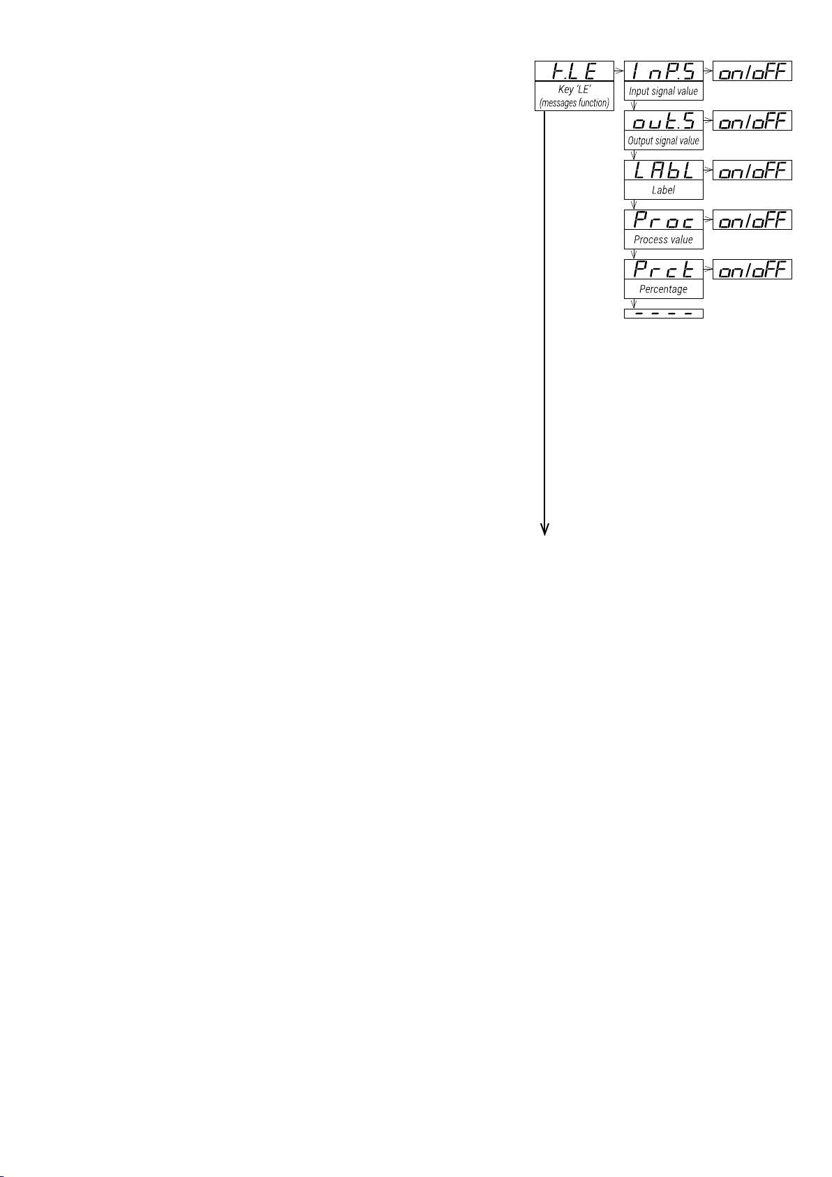
16.8. Key ‘LE’ (‘Messages’ function)
The key ‘LE’ () at the front of the instrument gives access to a
congurable set of information messages.
At the ‘Key LE (messages function)’ (K.LE) menu, select the
informations to be displayed when the front key ‘LE’ () is pressed
(see section 12.5). Select ‘on’ to activate each information.
• congure ‘Input signal value’ (I nP. S ) to ‘on’ to see the actual
input signal value and units (for example: ‘Inp hz 480’)
• congure ‘Output signal value’ (out.S) to ‘on’ to see the actual
output signal value and units (for example: ‘Out mA 08.3’)
• congure ‘Label’ (LAbL) to ‘on’ to read the value congured at
the ‘label’ parameter (see section 16.9).
• congure ‘Process value’ (Proc) to ‘on’ to read the process
value as congured at the process parameters (see section
16.5) (for example: ‘Proc 1500’).
• congure ‘Percentage’ (Prct) to ‘on’ to see the actual
percentage of signal, where ‘0’ is the value assigned to the
‘input signal low’ parameter, and ‘100’ is the value assigned to
the ‘input signal high’ parameter (see section 16.5) (for example:
‘Prct 23.5’).
When more than one parameter is set to ‘on’, values will be
displayed sequentially, in the same order as they are listed in the
menu, with a middle dash ‘-’ between them. When all information
has been displayed, the instrument returns to ‘normal mode’ of
operation.”
22 DR-I4F User's Manual
Page 23
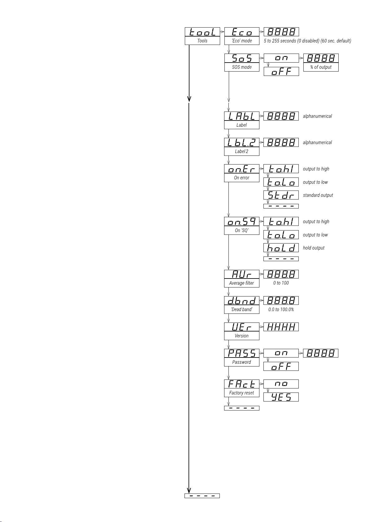
16.9. ‘Tools’ Menu
The ‘Tools’ (tool) menu groups several functions.
• at the ‘Eco mode’ (Eco) parameter, dene the
time to wait before the display is powered
off (while in ‘normal mode’ of operation).
Default value is 60 seconds. Congure ‘0’ to
disable the function and maintain the display
always on.
• at the ‘SOS mode’ (SoS) parameter select
‘on’ to activate the output signal to a
predened value. Select the value from 0
to 100% of the active output range (4/20
mA or 0/10 V DC). To deactivate the ‘SOS
mode’ select ‘oFF.’ See section 6 for more
information on the ‘SOS mode’.”
• at the ‘Label’ (LAbL) parameter, dene an
alphanumerical value to be displayed on the
display, when the instrument is in ‘normal
mode’ of operation, or at the ‘messages’
function when the key ‘LE’ () is pressed.
The label can be used to identify the
instrument with its own internal factory code.
If more than four characters are needed,
congure the ‘Label 2’ (LbL.2) parameter. The
total label value is the characters at ‘label’
followed by the characters at ‘label2’. For
additional information and a list of available
characters, see section 7.
• at the ‘On error’ (on.Er) parameter, congure
the behavior of the output signal, in case of
hardware error at the input (see section 19).
• select ‘Output to high’ (to.hI) to force the
output signal to overrange to maximum
value
• select ‘Output to low’ (to.Lo) to force the
output signal to underrange to minimum
value
• select ‘Standard output’ (Stdr) to overrange
output signal to maximum value in case of
input signal overrange, and to underrange
output signal to minimum value in case of
input signal underrange.
• at the ‘On ‘SQ’’ (on.Sq) parameter, congure
the behavior of the output signal when the
operator is inside ‘conguration menu’ (see
section 12.3).
• select ‘Output to high’ (to.hI) to force the
output signal to overrange to maximum
value
• select ‘Output to low’ (to.Lo) to force the
output signal to underrange to minimum
value
• select ‘Hold output’ (hoLd) to hold the
output signal while the operator remains
inside ‘conguration menu’.
• at the ‘Average lter’ (AVr) parameter,
congure the recursive lter to be applied
to measured input signal. The lter can be
used to reduce oscillations on noisy signals.
Congure the lter strength between ‘0’ and
‘100’. The lter is stronger with higher values.
Increasing the strength of the lter slows the
response speed of the instrument. Value ‘0’
disables the lter.
• at the ‘Dead band’ (d.bnd) parameter set
a value between ‘0.0’ % and ‘100.0’ %. This
is a percentage of the ‘input signal high’
parameter congured at the ‘Advanced
scaling’ section. Input signals below this
23Conguration Menu
Page 24

value, are treated as a ‘0’. This parameter applies to all measuring ranges.
• the ‘Version’ (VEr) parameter informs about the rmware version running in the instrument.
• at the ‘Password’ (PASS) parameter dene a 4 digit code to block access to the ‘conguration menu’.
Activate the password to prevent access to the instrument conguration by non authorized personnel. To
activate the ‘Password’ function select ‘on’, enter the code and validate. The password will be requested
when entering the ‘conguration menu’. The password does not block access to the ‘force’ menu. To
deactivate the password, select ‘oFF’.
• at the ‘Factory reset’ (FAct) parameter select ‘yes’ to activate the ctory conguration (see section 18 for a
list of factory default parameters).
24 DR-I4F User's Manual
Page 25
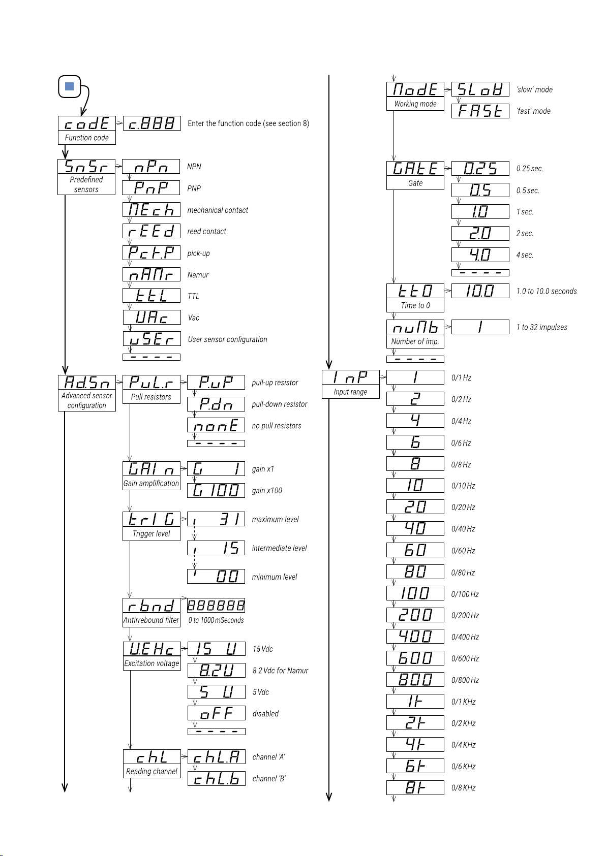
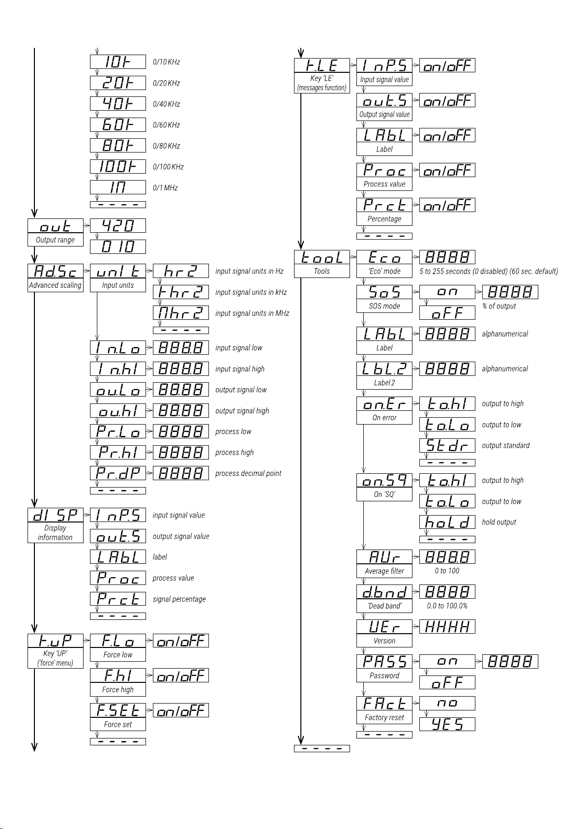
17. Full Configuration Menu
Press ‘SQ’ () for 1 second to access the ‘conguration menu’. For a description on how to operate inside the
menus see section 12. For a full vision of the ‘conguration menu’ structure see section 16.
25Full Conguration Menu
Page 26
26 DR-I4F User's Manual
Page 27

18. Factory Default Parameters
Function code (codE)
Predened sensors (SnSr)
Advanced sensor conguration (Ad.Sn)
Pull resistors (PuL.r)
Gain amplication (GAIn)
Trigger level (TrI G)
Antirrebound lter (rnbd)
Excitation voltage (V. E Xc)
Reading channel (chL)
Calculation mode (ModE)
Gate (GAtE)
Time to 0 (tt0)
Number of impulses (nuMb)
Input range (InP)
Output range (out)
Advanced scaling (Ad.Sc)
Units (unIt)
Input signal low (In.Lo)
Input signal high (In.hI)
Output signal low (ou.Lo)
Output signal high (ou.hI)
Process low (Pr.Lo)
Process high (Pr. hI)
Process decimal point (Pr.dP)
Display information (dISP) Input signal value (In P. S)
Key ‘UP’ (‘force’ menu) (K.uP)
Force low (F. Lo)
Force high (F. hI)
Force set (FSEt)
Key ‘LE’ (‘messages’ function) (K.LE)
Input signal value (In P. S)
Output signal value (out.S)
Label (LAbL)
Process value (Proc)
Percentage (Prct)
Too l s (tooL)
‘Eco’ mode (Eco)
SOS mode (SoS)
Label (LAbL)
Label 2 (LbL.2)
On error (on.Er)
On ‘SQ’ (on.Sq)
Average lter (AVr)
Dead band (d.bnd)
Password (PASS)
025
npn
pull-up
x1
25
0 [milliseconds]
15 V DC
‘B’
fast
0.5 [seconds]
1.0 [seconds]
1
0/1K Hz
4/20 mA
kHertz
0.0 [kHz]
1.0 [kHz]
4.00 [mA]
20.00 [mA]
0
1000
xxxx
on
on
on
off
on
off
off
off
60 [seconds]
off
LAbL
---- (disabled)
to.hI (output to maximum value)
to.hI (output to maximum value)
0 (disabled)
0.0 (disabled)
off (disabled)
(c.025)
(nPn)
(P.uP)
(G 1)
(15 V)
(FASt)
(1K)
(420)
(khrZ)
RESET TO DEFAULT FACTORY PARAMETERS
To recover the instrument to default factory parameters, enter into ‘conguration menu’ and go to ‘Tools’ / ‘Factory
reset’ and select ‘yes’
• access the ‘conguration menu’ (press key ‘SQ’ () for 1 second)
• press key ‘UP’ () to locate ‘tools’ and press ‘SQ’ ()
27Factory Default Parameters
Page 28
• press key ‘UP’ () to locate ‘Factory reset’ and press ‘SQ’ ()
• value ‘no’ appears on display, press key ‘UP’ () and ‘Yes’ appears
• press key ‘SQ’ () to apply the factory reset
• the LEDs light a round shape while the new conguration is applied
• the start up message appears (‘SEnSor nPn 1.000 kHz’)
• the actual signal input value is displayed
• the instrument is in ‘normal mode’ of operation
19. Error Codes and Messages
In case of error, the error code is shown ashing on the digits. The error code remains active on display until the
problem that caused the error is solved. In case of multiple error codes, solve the rst problem to see the next
active error code. The error code is not visible inside ‘conguration mode’ or inside the ‘force’ menu.
While on error, the output can be congured to overrange (to 21 mA, 10.4 V DC), to underrange (to 3 mA or -0.05
V DC) or to hold value. See the ‘On error’ (on.Er) parameter at section 16.9.
Table 13 | Error Codes
Error
‘Er.01’
‘Er.04’
‘Er.05’
‘Er.08’
‘Er.09’
‘Er.10’
Description
Password error. The password code entered is not correct.
Output hardware overrange. The output signal should be higher than the maximum output
signal that can be generated.
Output hardware underrange. The output signal should be lower than the minimum output
signal that can be generated.
Scaled input slope not valid. The value at ‘Input signal high’ (In.hI) has to be higher than
the value at ‘Input signal low’ (In.Lo). Enter a different value to validate the parameter (see
section 16.5).
Scaled output slope not valid. The values for ‘Output signal low’ (ou.Lo) and ‘Output signal
high’ (ou.hI) can not be the same. Enter a different value to validate the parameter (see
section 16.5).
Scaled process display slope not valid. The values for ‘Process low’ (Pr.Lo) and ‘Process
high’ (Pr.hI) can not be the same. Enter a different value to validate the parameter (see
section 16.5).
The instrument can show ‘messages’, which are not ‘errors’ and do not affect the output signal, and do not trigger
the ‘On error’ (on.Er) function. Below is a list of possible ‘messages’.
Table 14 | Messages
Error
‘d.oVr’
‘d.udr’
‘-nA-’
Description
Display overrange. The display value should be higher than the maximum value
that can be displayed.
Display underrange. The display value should be lower than the minimum value
that can be displayed.
Function not available. For the actual conguration, the function is not available.
20. Precautions on Installation
Important: Risk of electrical shock. Instrument terminals can be connected to dangerous voltage.
Instrument protected with double isolation. No earth connection required.
Instrument conforms to CE rules and regulations.
This instrument has been designed and veried conforming to the 61010-1 CE Security Regulation, for industrial
applications. Installation of this instrument must be performed by qualied personnel only. This manual contains
the appropriate information for the installation. Using the instrument in ways not specied by the manufacturer
may lead to a reduction of the specied protection level. Disconnect the instrument from all external circuits
before starting any maintenance and / or installation action.
The instrument does not have a general switch and will start operation as soon as power is connected. The
instrument does not have protection fuse, the fuse must be added during installation.
The instrument is designed to be DIN rail mounted, inside a closed cabinet, protected from direct impacts. An
appropriate ventilation of the instrument must be assured. Do not expose the instrument to excess of humidity.
28 DR-I4F User's Manual
Page 29
Maintain clean by using a humid rag and do NOT use abrasive products such as alcohols, solvents, etc. General
recommendations for electrical installations apply, and for proper functionality we recommend: if possible, install
the instrument far from electrical noise or magnetic eld generators such as power relays, electrical motors, speed
variators,
... If possible, do not install along the same conduits power cables (power, motor controllers, electrovalves, ...)
together with signal and/or control cables. The use of shielded cables is recommended to prevent the coupling
of environmental electromagnetic noise, connected to earth only one cable end side. Before proceeding to the
power connection, verify that the voltage level available matches the power levels indicated in the label on the
instrument. In case of re, disconnect the instrument from the power line, re alarm according to local rules,
disconnect the air conditioning, at tack re with carbonic snow, never with water.
Important: Conformity with security regulations EN-61010-1 requires a closed front cover. There is no need to open
the front cover under normal usage or conguration. The output terminal prevents the front cover from opening.
An open front cover may expose areas with dangerous voltages. Remove connections with dangerous voltages
before opening. Only to be performed by qualied operators.”
21. CE Declaration of Conformity
Products
The manufacturer declares that the instruments indicated comply with the
directives and rules indicated below.
Electromagnetic compatibility
directive 2014/30/EU
Low voltage directive 2014/35/EU
ROHS directive 2011/65/EU
WEEE directive 2012/19/EU
Security rules EN-61010-1
Instrument Fixed, Permanently connected
Pollution degree 1 and 2 (without condensation)
Isolation Double
Overvoltage category 2
Category of measure CAT-II 300V,
Electromagnetic compatibility rules EN-61326-1
EM environment Industrial
CISPR 11 Instrument Class A & Class B Group 1
According to directive 2012/19/EU, electronic equipment cycled in a selective and controlled way at
the end of its useful life.
DR-I4F
29CE Declaration of Conformity
Page 30
WARRANTY/DISCLAIMER
OMEGA ENGINEERING, INC. warrants this unit to be free of defects in materials and workmanship for a period
of 13 months from date of purchase. OMEGA’s WARRANTY adds an additional one (1) month grace period to
the normal one (1) year product warranty to cover handling and shipping time. This ensures that OMEGA’s
customers receive maximum coverage on each product.
If the unit malfunctions, it must be returned to the factory for evaluation. OMEGA’s Customer Service
Department will issue an Authorized Return (AR) number immediately upon phone or written request.
Upon examination by OMEGA, if the unit is found to be defective, it will be repaired or replaced at no charge.
OMEGA’s WARRANTY does not apply to defects resulting from any action of the purchaser, including but
not limited to mishandling, improper interfacing, operation outside of design limits, improper repair, or
unauthorized modification. This WARRANTY is VOID if the unit shows evidence of having been tampered
with or shows evidence of having been damaged as a result of excessive corrosion; or current, heat,
moisture or vibration; improper specification; misapplication; misuse or other operating conditions outside
of OMEGA’s control. Components in which wear is not warranted, include but are not limited to contact
points, fuses, and triacs.
OMEGA is pleased to offer suggestions on the use of its various products. However, OMEGA neither assumes
responsibility for any omissions or errors nor assumes liability for any damages that result from the use of its
products in accordance with information provided by OMEGA, either verbal or written. OMEGA warrants only
that the parts manufactured by the company will be as specified and free of defects. OMEGA MAKES NO OTHER
WARRANTIES OR REPRESENTATIONS OF ANY KIND WHATSOEVER, EXPRESSED OR IMPLIED, EXCEPT THAT OF
TITLE, AND ALL IMPLIED WARRANTIES INCLUDING ANY WARRANTY OF MERCHANTABILITY AND FITNESS FOR
A PARTICULAR PURPOSE ARE HEREBY DISCLAIMED. LIMITATION OF LIABILITY: The remedies of purchaser set
forth herein are exclusive, and the total liability of OMEGA with respect to this order, whether based on contract,
warranty, negligence, indemnification, strict liability or otherwise, shall not exceed the purchase price of the
component upon which liability is based. In no event shall OMEGA be liable for consequential, incidental or
special damages.
CONDITIONS: Equipment sold by OMEGA is not intended to be used, nor shall it be used: (1) as a “Basic
Component” under 10 CFR 21 (NRC), used in or with any nuclear installation or activity; or (2) in medical
applications or used on humans. Should any Product(s) be used in or with any nuclear installation or activity,
medical application, used on humans, or misused in any way, OMEGA assumes no responsibility as set
forth in our basic WARRANTY/DISCLAIMER language, and, additionally, purchaser will indemnify OMEGA
and hold OMEGA harmless from any liability or damage whatsoever arising out of the use of the Product(s)
in such a manner.
RETURN REQUESTS/INQUIRIES
Direct all warranty and repair requests/inquiries to the OMEGA Customer Service Department. BEFORE
RETURNING ANY PRODUCT(S) TO OMEGA, PURCHASER MUST OBTAIN AN AUTHORIZED RETURN (AR)
NUMBER FROM OMEGA’S CUSTOMER SERVICE DEPARTMENT (IN ORDER TO AVOID PROCESSING
DELAYS). The assigned AR number should then be marked on the outside of the return package and on any
correspondence.
The purchaser is responsible for shipping charges, freight, insurance and proper packaging to prevent
breakage in transit.
FOR WARRANTY RETURNS, please have the
following information available BEFORE contacting
OMEGA:
1. Purchase Order number under which the product
was PURCHASED,
2. Model and serial number of the product under
warranty, and
3. Repair instructions and/or specific problems
FOR NON-WARRANTY REPAIRS,
for current repair charges. Have the following
information available BEFORE contacting OMEGA:
1. Purchase Order number to cover the COST
of the repair,
2. Model and serial number of the product, and
3. Repair instructions and/or specific problems
relative to the product.
relative to the product.
OMEGA’s policy is to make running changes, not model changes, whenever an improvement is possible. This affords our customers the latest
in technology and engineering.
OMEGA is a trademark of OMEGA ENGINEERING, INC. © Copyright OMEGA ENGINEERING, INC. All rights reserved. This document may not
be copied, photocopied, reproduced, translated, or reduced to any electronic medium or machine-readable form, in whole or in part, without
the prior written consent of OMEGA ENGINEERING, INC.
consult OMEGA
Page 31

®
omega.com
Improving the world, one measurement at a time.
TM
UNIVERSAL
FLOW MONITORS
 Loading...