

Page 1
Page 2
OMEGAnet
SM
http://www.omega.com
On-Line Service
omega.com
OMEGA
®
TM
Internet e-mail
USA:
ISO 9001 Certified
USA and Canada: Sales Service: 1-800-826-6342 / 1-800-TC-OMEGASM
Mexico and
Latin America: Tel: (95) 800-TC-OMEGASM FAX: (95) 203-359-7807
Benelux: Postbus 8034, 1180 LA Amstelveen, The Netherlands
Czech Republic: Ostravska 767,733 01 Karvina
France: 9, rue Denis Papin, 78190 Trappes
Germany/Austria: Daimlerstrasse 26, D-75392 Deckenpfronn, Germany
United Kingdom: 25 Swannington Road, P.O. Box 7, Omega Drive,
ISO 9002 Certified Broughton Astley, Leicestershire, Irlam, Manchester,
One Omega Drive, Box 4047
Stamford, CT 06907-0047
Tel: (203) 359-1660
FAX: (203) 359-7700
e-mail: [email protected]
Customer Service: 1-800-622-2378 / 1-800-622-BESTSM
Engineering Service: 1-800-872-9436 / 1-800-USA-WHENS M
TELEX: 996404 EASYLINK: 62968934 CABLE: OMEGA
En Espanol: (95) 203 359-7803 e-mail: [email protected]
Tel: (31) 20 6418405 FAX: (31) 20 6434643
Toll Free in Benelux: 06 0993344
e-mail: [email protected]
Tel:42(69)6311899 FAX:42(69) 6311114
e-mail: [email protected]
Tel: (33) 130-621-400 FAX: (33) 130-699-120
Toll Free in France: 0800-4-06342
e-mail: [email protected]
Tel: 49 (07056) 3017 FAX: 49 (07056) 8540
Toll Free in Germany: 0130 11 21 66
e-mail: [email protected]
LE9 6TU, England M44 5EX, England
Tel: 44 (1455) 285520 Tel: 44 (161) 777-6611
FAX: 44 (1455) 283912 FAX: 44 (161) 777-6622
Toll Free in England: 0800-488-488
e-mail: [email protected]
Canada:
976 Bergar
Laval (Quebec) H7L 5A1
Tel: (514) 856-6928
FAX: (514) 856-6886
e-mail: [email protected]
It is the policy of OMEGA to comply with all worldwide safety and EMC/EMI regulations that apply.
OMEGA is constantly pursuing certification of its products to the European New Approach Directives.
OMEGA will add the CE mark to every appropriate device upon certification.
The information contained in this document is believed to be correct but OMEGA Engineering, Inc.
accepts no liability for any errors it contains, and reserves the right to alter specifications without notice.
WARNING: These products are not designed for use in, and should not be used for, patient connected
applications.
Page 3

Contents
1. GENERAL DESCRIPTION
2. MOUNTING INSTRUCTIONS
3. REPLACING FUSES
4. ASSEMBLY
5. SUPPLY VOLTAGE
6. CONNECTING TRANSMITTERS TO THE MULTIPLEXER
6.1 Two-Wire Transmitter
6.2 Three-Wire Transmitter
6.3 Four-Wire Transmitter
7. CONTROL
7.1 Enable/Test
7.2 Address
7.3 Address Polarity
7.4 Control Tables
7.4.1 True Low Setting
7.4.2 True High Setting
8. MULTI-DROP CONFIGURATION
9. SPECIFICATIONS
1
Page 4

1.GENERAL DESCRIPTION
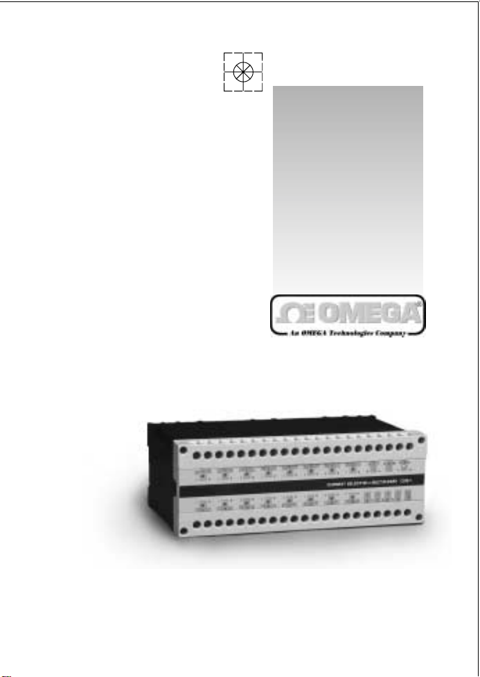
The DRA-CSM-1 is a multiplexer for 16 analog 4-20mA current loops.
The transmitter/transducer currents are input via "I" terminals. Each input is
protected by a 63mA fuse.
The current input is steered either to the output ("lo") terminal or to the negative
(COM) terminal of the power supply (PWR). Fifteen channels are routed to the
COM and only the selected one is routed to the output terminals, thus ensuring
a continuous and uninterrupted current loop.
The multiplexer's channel selection is controlled by 4 address lines, generated by
the PLC's discrete output module.
The unit provides 16, current limited (~40mA), voltage supply ("V") outputs. These
outputs are derived from the mux's power supply input and are used to feed twowire transmitters. The current limitation avoids fuse blowing in cases of shortcircuit of the transmitters' leads.
WARNING: Never connect a voltage source as an input to the
multiplexer. Its internal low dynamic impedance
will cause immediate fuse blowing.
2. MOUNTING INSTRUCTIONS
The DRA-CSM-1 is designed for standard DIN rail mounting.
Place the unit on the upper part of the mounting rail with the fastening tab facing
down. Loosen the tab slightly, using a suitable flat screwdriver, and attach the unit
to the rail. After releasing the tab, make sure that the unit is fastened securely in
place.
3. REPLACING FUSES
To replace a blown fuse, disassemble the unit as follows:
a. Take off both terminal strips by removing the four screws at the edges.
Note: This does not require disconnecting the cables connected to the strips.
b. Remove the front panel using a suitable flat screwdriver. Press down gently on
the plastic springloaded tabs located in the slots on either side of the unit.
2
Page 5
c. Disconnect the flat connectors from the front panel.
d. Replace the blown fuse.
WARNING: Never install a channel fuse rated more than
100mA, and main fuse rated more than 800mA.
4. ASSEMBLY
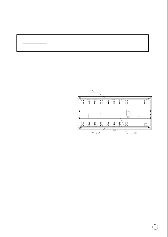
The DRA-CSM-1 unit includes three printed circuit cards designated as P.N 7016,
P.N 7017 and P.N 7030.
The printed circuit cards should occupy the slots in the enclosure according to fig1.
Connect the flat cables between the
printed circuit cards and the front
panel. The front panel must be
inserted into the grooves on both
sides of the case while pressing down
until a distinct "click" is heard.
Assembly is completed by laying the
terminal strips in place.
Figure 1.
Note: The terminal strips are polarized and must not be placed backwards.
5. POWER SUPPLY
The DRA-CSM-1 is supplied by a regulated power supply at a range of 15 to
40Vdc. This voltage is used to feed the connected transmitters via the multiplexer's
"V" terminals.
The DRA-CSM-1 unit adds about 350
5.1 MINIMUM SUPPLY VOLTAGE
The minimum supply voltage required to operate the multiplexer and the transmitters
fed by it can be calculated using the following equation:
Vmin = Vt + 0.02*(Rs+350)
W to the current loop
3
Page 6
Where:
Vmin - The minimum required supply voltage
Vt - The minimum required voltage specified for the connected
transmitter (at load=0)
Rs - Total loop load including leads' resistance and PLC's input impedance
Example:
The minimum operational voltage of a given transmitter is 12V.
The total loop load is 250W.
Solving the above voltage:
Vmin= 24Vdc
6. CONNECTING THE TRANSMITTERS TO THE MULTIPLEXER
6.1 TWO-WIRE TRANSMITTER
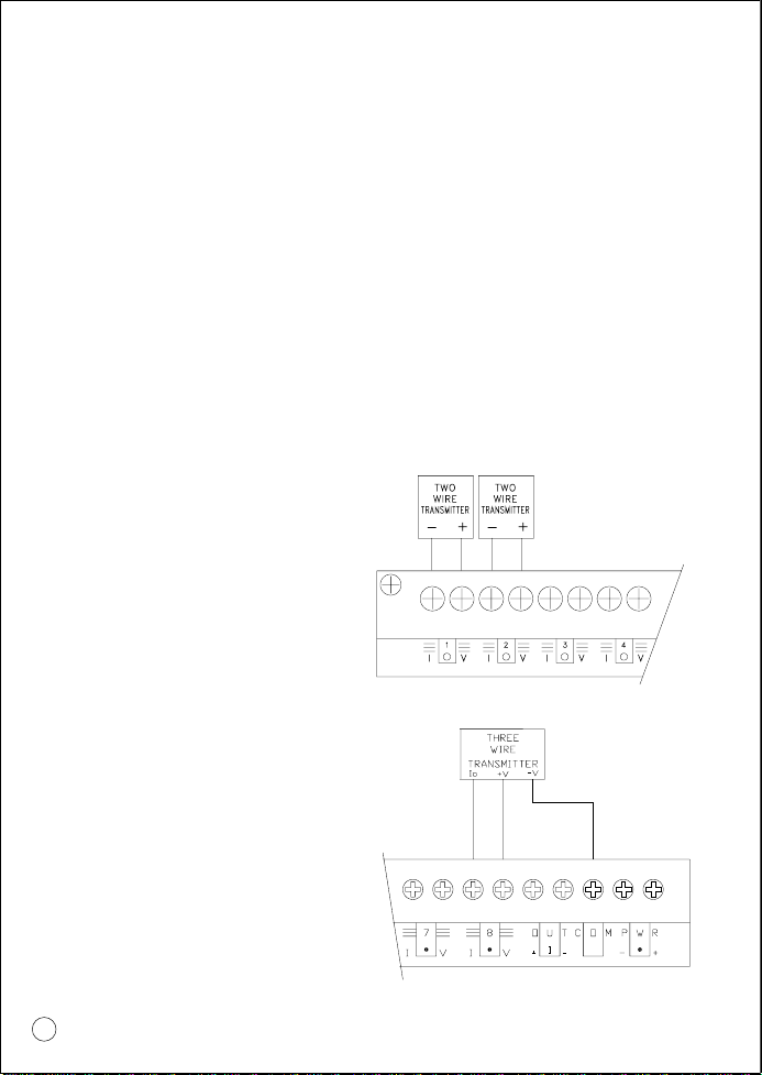
A Two-Wire transmitter is connected
so that its positive terminal is connected
to the "V" terminal, and its negative
terminal is connected to the "I" terminal.
(see fig 2.)
Figure 2.
6.2 THREE-WIRE TRANSMITTER
A Three-Wire transmitter is connected
so that its positive terminal "+V" is
connected to the multiplexer "V" terminal,
its negative terminal "-V" is connected
to the multiplexer's "COM" terminal and
the current output terminal "Io" is
connected to the DRA-CSM-1 "I"
terminal. (see fig 3).
4
Figure 3.
Page 7
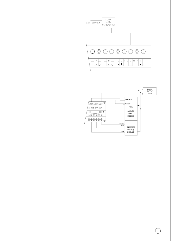
6.3 FOUR-WIRE TRANSMITTER
A Four-Wire transmitter is connected
so that its positive terminal is
connected to the "I" terminal, and its
negative terminal is connected to the
"COM" terminal. (see fig 4).
Figure 4.
7. CONTROL
The DRA-CSM-1 unit is controlled via
four address lines and one E/T
(Enable/T est) line. The control terminals
(Address and Enable), were designed
to receive control signals from TTL levels
up to 60V so that almost any PLC's DC
output module can be used. (see fig 5).
Figure 5.
7.1 ENABLE/TEST
The unit is enabled when "E/T" is in logical "0" (low) state. In a disabled state,
the DRA-CSM-1 outputs no current and reflects a Hi-Z state.
The disabled state of the DRA-CSM-1 multiplexer is used to check the functioning
of all the current inputs. This is performed by simultaneously injecting current pulses
to all 16 channels which cause the functioning channels to flash. This is a quick
and useful means to indicate a blown fuse.
7.2 ADDRESS
The required channel is selected by four address lines.
The operating voltage levels are:
"0" state 0V < Vaddress < 0.4V
"1" state 5V < Vaddress < 60V
5
Page 8
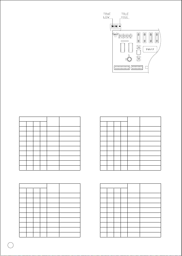
7.3 ADDRESS POLARITY (see fig 6)
Address polarity is controlled by three
internal pins and a jumper over two of
them, accessible behind the Enable
terminal. The unit is supplied with the
jumper set for "true low" control logic,
i.e. "0000" selects channel #16, and
"1111" selects channel #1.
Moving the jumper to the second
alternative, reverses the logic.
Figure 6.
Note: If the PLC and the DRA-CSM-1 are powered by separate power
supplies, then the negative terminals should be connected.
7.4 CONTROL TABLES
7.4.1 "True Low" Setting
ADDRESS BUS
A3
0
0
0
0
0
0
1
0
0
1
0
0
0
1
0
0
1
0
1
1
0
1
1
0
x
x
x
OUTPUT
E/T
0
0
0
0
0
0
0
0
1
CHANNEL
16
15
14
13
12
11
10
9
TEST MODE
A0A1A2
0
1
0
1
0
1
0
1
x
ADDRESS BUS
A3
0
0
1
0
0
1
1
0
1
1
0
1
0
1
1
0
1
1
1
1
1
1
1
1
x
x
x
OUTPUT
E/T
0
0
0
0
0
0
0
0
1
CHANNEL
8
7
6
5
4
3
2
1
TEST MODE
A0A1A2
0
1
0
1
0
1
0
1
x
7.4.2 "True High" Setting
ADDRESS BUS
A3
0
0
0
0
0
0
0
0
x
6
A0A1A2
0
0
0
1
0
0
0
1
0
1
1
0
0
0
1
1
0
1
0
1
1
1
1
1
x
x
x
E/T
0
0
0
0
0
0
0
0
1
OUTPUT
CHANNEL
1
2
3
4
5
6
7
8
TEST MODE
ADDRESS BUS
A3
0
0
1
0
0
1
1
0
1
1
0
1
0
1
1
0
1
1
1
1
1
1
1
1
x
x
x
OUTPUT
E/T
0
0
0
0
0
0
0
0
1
CHANNEL
9
10
11
12
13
14
15
16
TEST MODE
A0A1A2
0
1
0
1
0
1
0
1
x
Page 9
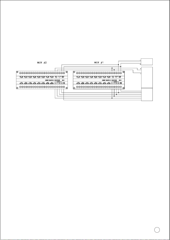
8. MULTI-DROP CONFIGURATION
In the disabled state (E=1), the multiplexer outputs no current and exhibits a high
Z state. This mode allows the connection of several DRA-CSM-1 units to one PLC's
analog input, by tying their output terminals and the address lines in parallel, and
applying individual Enable lines to select the desired multiplexer by disabling all
but one. (see fig 7)
POWER
SUPPLY
ANALOG +
ANALOG
PLC
ANALOG
INPUT
MODULE
ENABLE 1
MSB
DISCRETE
OUTPUT
LSB
MODULE
ENABLE 2
Figure 7
-
7
Page 10

9. SPECIFICATIONS
INPUTS
ANALOG INPUTS
(Reverse Polarity Protected)
Max Input Current
CONTROL INPUTS
Logic Levels
Logic Polarity
OUTPUTS
CURRENT OUTPUT
Switching time
Accuracy (Refer to Current Input)
"V" TERMINALS
"V" Voltage
Limitation Current
Automatic Temperature Shut-down
INDICATORS
16, 0/4-20mA Current loop
30mA
4 Address inputs
E/T Enable/Test input
Low: "0" < 0.4V
High: 5 < "1" < 60V
Selectable - True High/True Low
4-20mA, Current Loop
10mSec (into a resistive load)
0.01% maximum @ for the entire temperature range
V supply - 2.5V
40 ±1mA
o
Above 80
1 Yellow LED, Power-On indicator
16 Red LEDs, current activity indicators
C
SUPPLY
Supply Voltage
Supply Current Consumption
FUSES
Main Fuse
Channel Fuse
TEMPERATURE
Operating
Storage
HUMIDITY
HOUSING
Box
Terminals
WEIGHT
DIMENSIONS
8
15 - 40 Vdc (regulated)
15mA in operation mode,
120mA in Test mode
(transmitters not included)
630mA, Fast Blow (20x5 mm)
63mA, Fast Blow (20x5 mm)
o
C (32 to 158 oF)
0 to 70
-25 to +85
o
C (-13 to 185 oF)
5 to 95% Relative humidity, non condensing
Plastic Polycarbonate
According to IP50 DIN 40050
According to IP20 DIN 40050
0.75 Kg. (1.5 lb.)
73Hx200Wx121mmD
(2.88"x7.88"x4.76")
Page 11

OMEGA ENGINEERING, INC. warrants this unit to be free of defects in materials and workmanship
for a period of 13 months from date of purchase. OMEGA Warranty adds an additional one (1) month
grace period to the normal one (1) year product warranty to cover handling and shipping time. This
ensures that OMEGA’s customers receive maximum coverage on each product. If the unit should malfunction,
it must be returned to the factory for evaluation. OMEGA’s Customer Service Department will issue an Authorized
Return (AR) number immediately upon phone or written request. Upon examination by OMEGA, if the unit is
found to be defective it will be repaired or replaced at no charge. OMEGA’s WARRANTY does not apply to defects
resulting from any action of the purchaser, including but not limited to mishandling, improper interfacing,
operation outside of design limits, improper repair, or unauthorized modification. This WARRANTY is VOID if
the unit shows evidence of having been tampered with or shows evidence of being damaged as a result
of excessive corrosion; or current, heat, moisture or vibration; improper specification; misapplication; misuse
or other operating conditions outside of OMEGA’s control. Components which wear are not warranted, including
but not limited to contact points, fuses, and triacs.
OMEGA is pleased to offer suggestions on the use of its various products. However,
OMEGA neither assumes responsibility for any omissions or errors nor assumes
liability for any damages that result from the use of its products in accordance
with information provided by OMEGA, either verbal or written. OMEGA warrants
only that the parts manufactured by it will be as specified and free of defects.
OMEGA MAKES NO OTHER WARRANTIES OR REPRESENTATIONS OF ANY KIND
WHATSOEVER, EXPRESSED OR IMPLIED, EXCEPT THAT OF TITLE, AND ALL
IMPLIED WARRANTIES INCLUDING ANY WARRANTY OF MERCHANTABILITY AND
FITNESS FOR A PARTICULAR PURPOSE ARE HEREBY DISCLAIMED. LIMITATION
OF LIABILITY: The remedies of purchaser set forth herein are exclusive and the
total liability of OMEGA with respect to this order, whether based on contract,
warranty, negligence, indemnification, strict liability or otherwise, shall not exceed
the purchase price of the component upon which liability is based. In no event
shall OMEGA be liable for consequential, incidental or special damages.
CONDITIONS: Equipment sold by OMEGA is not intended to be used, nor shall it be used: (1) as a “Basic
Component” under 10 CFR 21 (NRC), used in or with any nuclear installation or activity; or (2) in medical
applications or used on humans. Should any Product(s) be used in or with any nuclear installation or activity,
medical application, used on humans, or misused in any way, OMEGA assumes no responsibility as set forth
in our basic WARRANTY / DISCLAIMER language, and additionally, purchaser will indemnify OMEGA and
hold OMEGA harmless from any liability or damage whatsoever arising out of the use of the
Product(s) in such a manner.
Direct all warranty and repair requests/inquiries to the OMEGA Customer Service Department.
BEFORE RETURNING ANY PRODUCT(S) TO OMEGA, PURCHASER MUST OBTAIN AN AUTHORIZED
RETURN (AR) NUMBER FROM OMEGA’S CUSTOMER SERVICE DEPARTMENT (IN ORDER TO AVOID
PROCESSING DELAYS). The assigned AR number should then be marked on the outside of the return
package and on any correspondence.
The purchaser is responsible for shipping charges, freight, insurance and proper packaging to prevent
breakage in transit.
FOR WARRANTY RETURNS, please have the
following information available BEFORE contacting
OMEGA:
1. P.O. number under which the product was
PURCHASED,
2. Model and serial number of the product under
warranty, and
3. Repair instructions and/or specific problems
relative to the product.
OMEGA’s policy is to make running changes, not model changes, whenever an improvement is possible.
This affords our customers the latest in technology and engineering.
OMEGA is a registered trademark of OMEGA ENGINEERING, INC.
© Copyright 1996 OMEGA ENGINEERING, INC. All rights reserved. This document may not be copied,
photocopied, reproduced, translated, or reduced to any electronic medium or machine-readable form, in
whole or in part, without prior written consent of OMEGA ENGINEERING, INC.
WARRANTY/DISCLAIMER
RETURN REQUESTS / INQUIRIES
FOR NON-WARRANTY REPAIRS, consult
OMEGA for current repair charges. Have the
following information available BEFORE
contacting OMEGA:
1. P.O. number to cover the COST
of the repair,
2. Model and serial number of product, and
3. Repair instructions and/or specific
problems relative to the product.
Page 12

Where Do I Find Everything I Need for
Process Measurement and Control?
OMEGA…Of Course!
TEMPERATURE
⻬ Thermocouple, RTD & Thermistor Probes,
Connectors, Panels & Assemblies
⻬ Wire: Thermocouple, RTD & Thermistor
⻬ Calibrators & Ice Point References
⻬ Recorders, Controllers & Process Monitors
⻬ Infrared Pyrometers
PRESSURE, STRAIN AND FORCE
⻬ Transducers & Strain Gauges
⻬ Load Cells & Pressure Gauges
⻬ Displacement Transducers
⻬ Instrumentation & Accessories
FLOW/LEVEL
⻬ Rotameters, Gas Mass Flowmeters & Flow Computers
⻬ Air Velocity Indicators
⻬ Turbine/Paddlewheel Systems
⻬ Totalizers & Batch Controllers
pH/CONDUCTIVITY
⻬ pH Electrodes, Testers & Accessories
⻬ Benchtop/Laboratory Meters
⻬ Controllers, Calibrators, Simulators & Pumps
⻬ Industrial pH & Conductivity Equipment
DATA ACQUISITION
⻬ Data Acquisition & Engineering Software
⻬ Communications-Based Acquisition Systems
⻬ Plug-in Cards for Apple, IBM & Compatibles
⻬ Datalogging Systems
⻬ Recorders, Printers & Plotters
HEATERS
⻬ Heating Cable
⻬ Cartridge & Strip Heaters
⻬ Immersion & Band Heaters
⻬ Flexible Heaters
⻬ Laboratory Heaters
ENVIRONMENTAL
MONITORING AND CONTROL
⻬ Metering & Control Instrumentation
⻬ Refractometers
⻬ Pumps & Tubing
⻬ Air, Soil & Water Monitors
⻬ Industrial Water & Wastewater Treatment
⻬ pH, Conductivity & Dissolved Oxygen Instruments
M2613/0197
 Loading...