

Page 1
Page 2
OMEGAnet®On-Line Service Internet e-mail
http://www.omega.com [email protected]
Servicing North America:
USA: One Omega Drive, Box 4047
ISO 9001 Certified
Stamford, CT 06907-0047
Tel: (203) 359-1660 FAX: (203) 359-7700
e-mail: [email protected]
Canada: 976 Bergar
Laval (Quebec) H7L 5A1
Tel: (514) 856-6928 FAX: (514) 856-6886
e-mail: [email protected]
For immediate technical or application assistance:
USA and Canada: Sales Service: 1-800-826-6342 / 1-800-TC-OMEGA
Customer Service: 1-800-622-2378 / 1-800-622-BEST
Engineering Service: 1-800-872-9436 / 1-800-USA-
SM
WHEN
TELEX: 996404 EASYLINK: 62968934 CABLE: OMEGA
SM
SM
Benelux: Postbus 8034, 1180 LA Amstelveen, The Netherlands
Czech Republic: ul. Rude armady 1868, 733 01 Karvina-Hranice
France: 9, rue Denis Papin, 78190 Trappes
Germany/Austria: Daimlerstrasse 26, D-75392 Deckenpfronn, Germany
Mexico and
Latin America: Tel: (95) 800-826-6342 FAX: (95) 203-359-7807
En Espan ol: (95) 203-359-7803
e-mail: [email protected]
It is the policy of OMEGA to comply with all worldwide safety and EMC/EMI regulations that apply. OMEGA is constantly pursuing certification of its products to the European
New Approach Directives. OMEGA will add the CE mark to every appropriate device upon certification.
The information contained in this document is believed to be correct, but OMEGA Engineering, Inc. accepts
no liability for any errors it contains, and reserves the right to alter specifications without notice.
WARNING: These products are not designed for use in, and should not be used for, patient-connected applications.
United Kingdom: One Omega Drive, River Bend Technology Centre
ISO 9002 Certified Northbank, Irlam, Manchester
DR601
Servicing Europe:
Tel: (31) 20 6418405 FAX: (31) 20 6434643
Toll Free in Benelux: 0800 0993344
e-mail: [email protected]
Tel: 420 (69) 6311899 FAX: 420 (69) 6311114
Toll Free: 0800-1-66342
e-mail: [email protected]
Tel: (33) 130-621-400 FAX: (33) 130-699-120
Toll Free in France: 0800-4-06342
e-mail: [email protected]
Tel: 49 (07056) 3017 FAX: 49 (07056) 8540
Toll Free in Germany: 0130 11 21 66
e-mail: [email protected]
M44 5EX, England
Tel: 44 (161) 777-6611 FAX: 44 (161) 777-6622
Toll Free in the United Kingdom: 0800-488-488
e-mail: [email protected]
M-3344 02/99
Page 3
User Guide: Contents
Contents Page
Using this manual . . . . . . . . . . . . . . . . . . . . . . . .2
Layout of Controls . . . . . . . . . . . . . . . . . . . . . . . .3
Getting Started . . . . . . . . . . . . . . . . . . . . . . . . . . .4
General . . . . . . . . . . . . . . . . . . . . . . . . . . . . . . . .5
Operation Mode
Zero & mm/inch . . . . . . . . . . . . . . . . . . . .8
Preset . . . . . . . . . . . . . . . . . . . . . . . . . . . .9
Maximum/Minimum . . . . . . . . . . . . . . . . .11
Setup Mode
Menus . . . . . . . . . . . . . . . . . . . . . . . . . . .13
Preset . . . . . . . . . . . . . . . . . . . . . . . . . . .14
Limits . . . . . . . . . . . . . . . . . . . . . . . . . . .19
Probes . . . . . . . . . . . . . . . . . . . . . . . . . . .24
Resolution . . . . . . . . . . . . . . . . . . . . . . . .29
Direction . . . . . . . . . . . . . . . . . . . . . . . . .30
Reference mark . . . . . . . . . . . . . . . . . . . .31
Contents Page
Show . . . . . . . . . . . . . . . . . . . . . . . . . . . .35
Units . . . . . . . . . . . . . . . . . . . . . . . . . . . .36
External . . . . . . . . . . . . . . . . . . . . . . . . . .37
Print . . . . . . . . . . . . . . . . . . . . . . . . . . . . .38
RS232 & Program . . . . . . . . . . . . . . . . . .41
Lock . . . . . . . . . . . . . . . . . . . . . . . . . . . .43
Password . . . . . . . . . . . . . . . . . . . . . . . .45
Default . . . . . . . . . . . . . . . . . . . . . . . . . . .46
Errors . . . . . . . . . . . . . . . . . . . . . . . . . . . . . . . . .47
Specification . . . . . . . . . . . . . . . . . . . . . . . . . . . .49
Warranty/Disclaimer . . . . . . . . . . . . . . . . . . . . . . .
Contents
1
M-3344 02/99DR601
Page 4
Using this manual
The Digital Readout functions are covered in two
sections:
Operation mode
Setup mode
Operation mode shows you how to use the functions
which are immediately available to you without the need
to first set them up.
Setup mode shows you how to use the functions
which are accessed in setup mode or which must first
be configured using Setup mode.
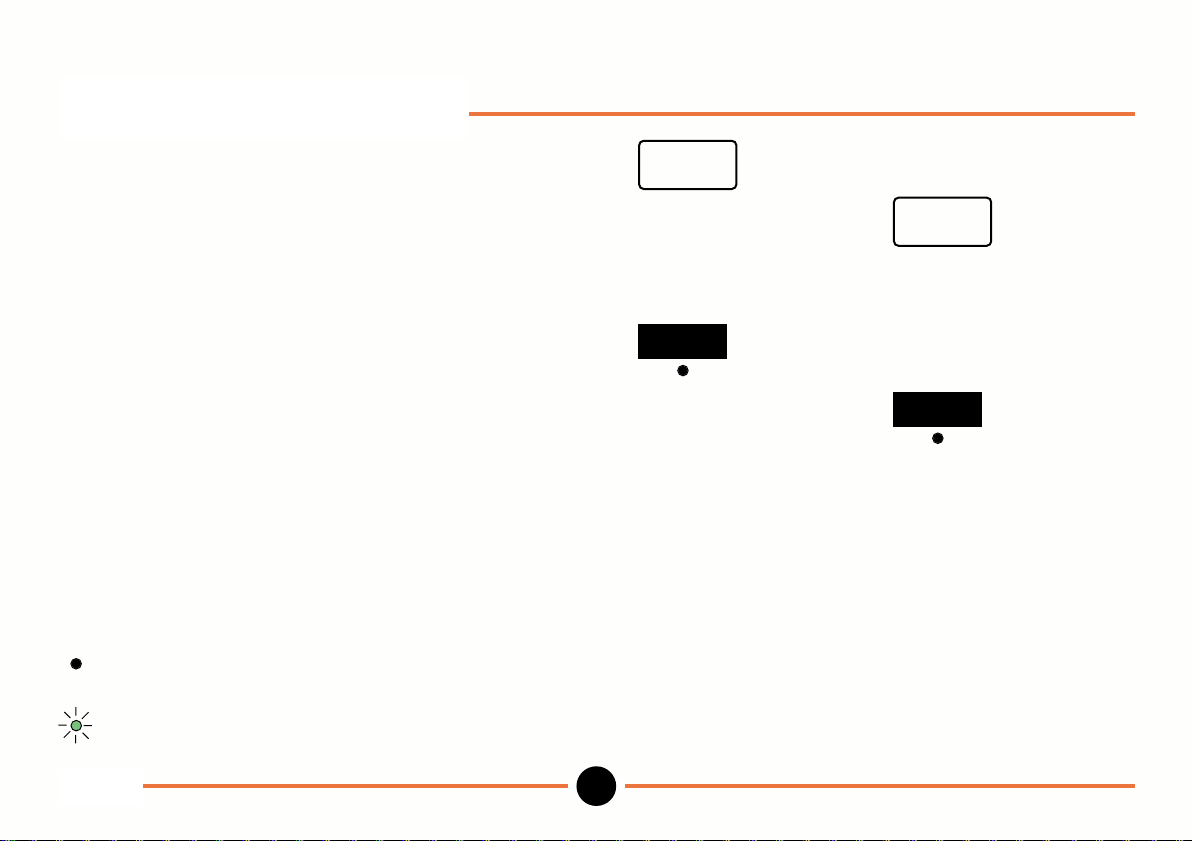
The following symbols are adopted in this manual:
indicates that the lamp is on
indicates that a lamp is flashing
represents a key which performs a
specific action
e.g.
represents a soft key
e.g
enter
preset
DR601
2
M-3344 02/99
Page 5
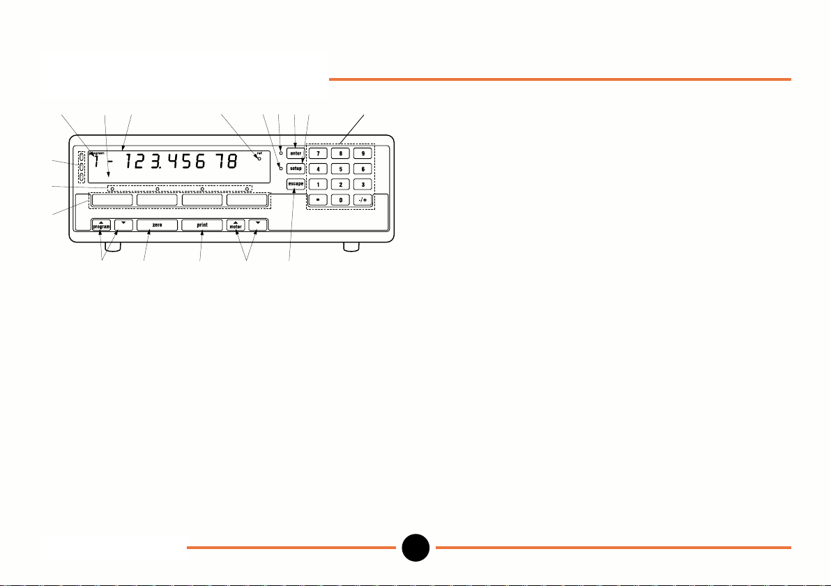
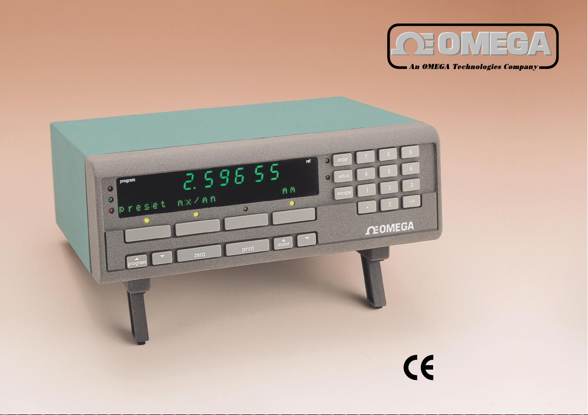
Layout of controls
preset
mx/mn
mm
1217 314121113 16
4
5
6
7
8 9 10 15
1. Numeric display - shows readings.
2. Information display - shows user information and
soft key legends.
3. Reference lamp - on when in reference mode.
4. Range lamps - top: out of tolerance high.
middle: within tolerance.
5. Soft key lamps - lit only when the function is
6. Soft keys - perform the function shown on
Layout of controls
bottom: out of tolerance low.
available.
the information display.
7. Program keys - increment or decrement
program number (1-9).
8. Zero key - zeros the numeric display.
9. Print key - sends the information on the
numeric display to a printer or
PC.
10. Motor keys - positions the tip of the Linear
Encoder (drive version only)
11. Enter key - completes number entry and
moves to the next selection.
12. Enter lamp - flashes, prompting you to
press the enter key.
13. Setup key - selects the setup menu.
14. Setup lamp - lamp is on when in setup
mode.
15. Escape key - aborts number entry and takes
you back to the previous
selection.
16. Numeric keys - to enter numeric information.
17. Program number - shows number selected by
display program keys.
3
M-3344 02/99DR601
Page 6
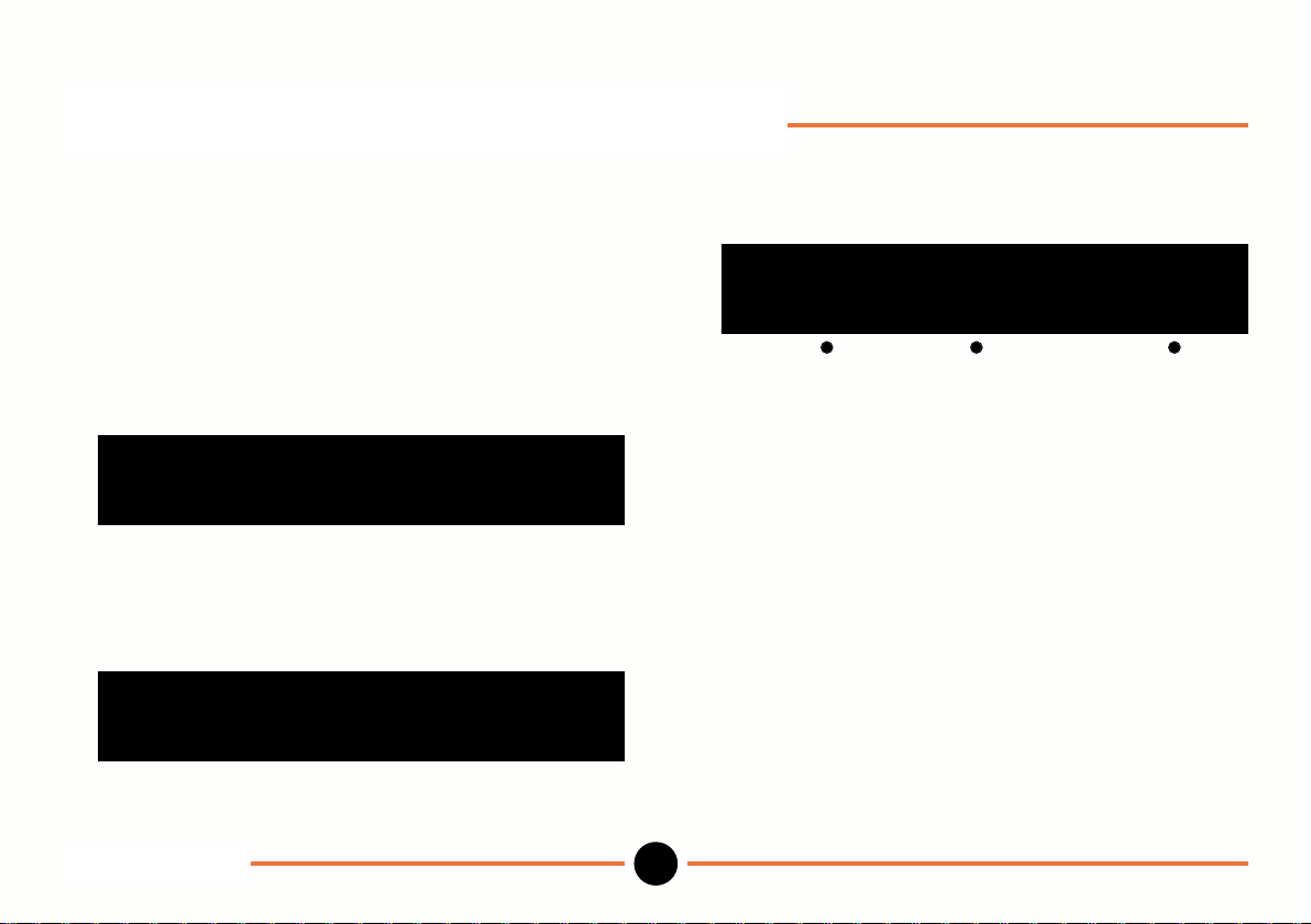
Getting started: Factory settings
1. Connect the probe (Linear Encoder or Digital Probe)
(see Digital Benchtop Meter Installation Manual).
2. Switch the power ON.
3. The Digital Readout will run through a start-up
routine. If the readout has not been connected to the
probe before, you will see the following display:
move probe tip *
Move the probe tip and the display will change to the
following:
press zero to continue
Press the zero key and the display will change to
the following.
0.0000
preset mx/mn mm
The system is now ready to start measuring.
Note: To establish the actual position within the
stroke of a Digital Probe, press escape in
place of zero in the above sequence.
Getting started
4
M-3344 02/99DR601
Page 7
General
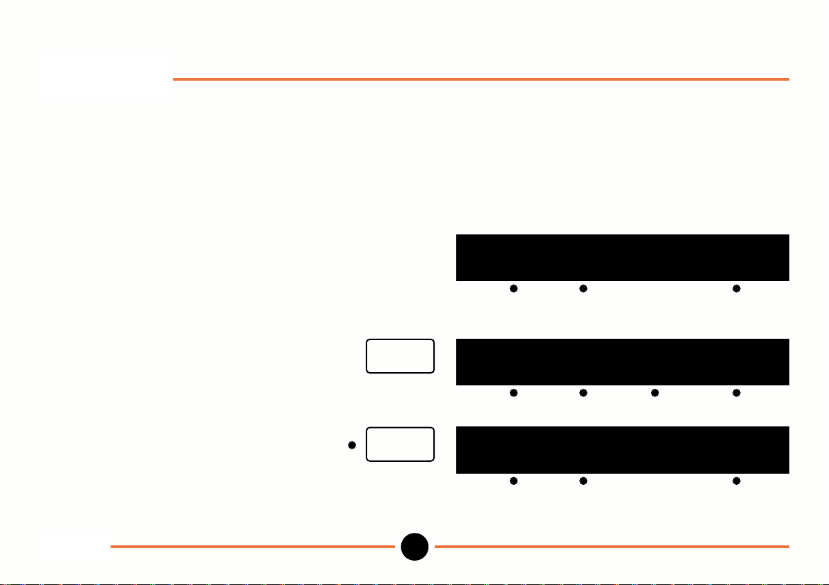
There are two modes of use Operation and Setup. The Digital Readout will always be in the Operation mode
following power-up.
In Operation mode the setup lamp is OFF.
In Setup mode the setup lamp is ON.
To enter Setup mode.
First make sure that you are at the main
operation menu
(if not press escape key until you are).
preset mx/mn mm
88.8888
Then press setup.
setup
preset limit probe more
To enter operation mode
(main operation menu)
Press setup.
Note: These are the factory defaults. To show or hide operation menus refer to show menu in Setup mode.
General
DR601
setup
preset mx/mn mm
5
88.8888
M-3344 02/99
Page 8
General: continued
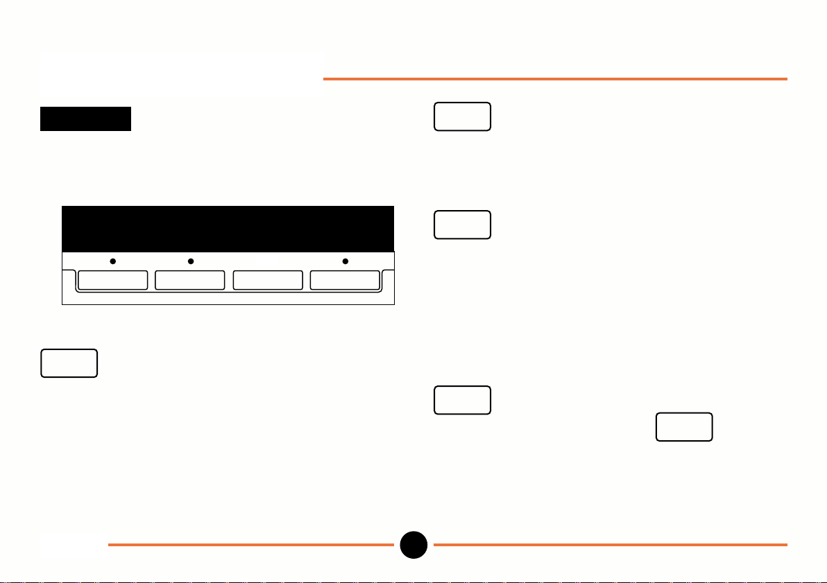
soft keys
Up to 4 menu items can be displayed at any one time.
When the lamp above a key is lit it indicates that the
function is available.
88.8888
preset mx/mn mm
Pressing the soft key results in an action taking place.
enter
Used to:
Enter lamp flashes prompting you to press enter key.
key
save numbers keyed in.
save settings after they have changed.
move to the next step in a menu sequence.
escape
Used to:
setup
Switches between Operation & Setup mode.
Note: Escape from preset, mx/mn or scan menus to
In Setup mode.
setup
Operation mode (ensure you press first to save
current change).
key
revert to previous number entered or previous step
in a menu sequence without saving changes.
key
main operation menu before pressing setup key.
key can be pressed at any stage to revert to
enter
General
DR601
6
M-3344 02/99
Page 9
General: continued
Programs
There are 10 programs allowing you to store up to 10
presets and 10 sets of limits. These can be used with a
single probe (Linear Encoder or Digital Probe) or pair of
probes for A+B or A-B measurements.
Alternatively each program can have a different probe
(or probe pair) assigned to it, allowing up to 10 probes,
(or probe pairs), to be connected to the Digital Readout.
Each probe, (or probe pair), may have its own preset
and limits. The program selected determines which
probe has its reading displayed.
program
The and keys are used to
select the program. When the Digital Readout is
switched on it automatically goes into the standard
program for which there is no number displayed. The
other 9 programs are numbered 1 to 9.
When moving from the Operation mode to the Setup
mode and vice versa the Digital Readout reverts to the
standard program.
Some of the setup menus are only available in the
standard program, as the settings for these apply to the
whole instrument and are not specific to individual
programs.
For each program the resolution, direction and
reference menus apply to the probe that is being used.
If the same probe is used in more than one program
these parameters can be changed on any of the
programs which use this probe.
In addition to moving to the next or previous program,
the and keys behave like the
program
enter key, saving a number or setting after it has been
changed. This allows you to change a setting in one
program and move to the next with one key press.
General
7
M-3344 02/99DR601
Page 10
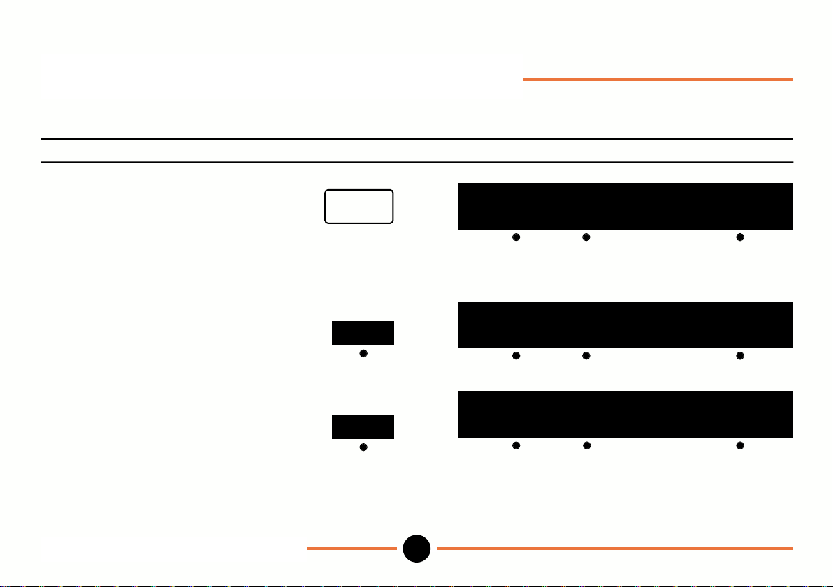
Operation mode: Zero & mm/inch
Operation Key stroke Display
To zero the numeric display and
establish an absolute datum.
Press zero.
To Change between inches and mm proceed as follows.
To select inch.
Toggle to inch.
To select mm.
Toggle to mm.
zero
mm
inch
Operation mode: zero & mm/inch
DR601
0.0000
preset mx/mn mm
88.8888
preset mx/mn inch
88.8888
preset mx/mn mm
8
M-3344 02/99
Page 11
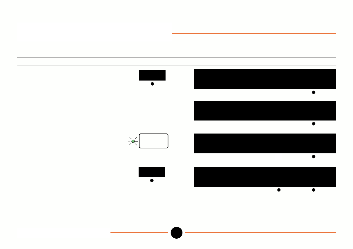
Operation mode: Preset
(Allows you to key in and load a preset in the standard program and switch between absolute and incremental datum)
To key in and load a preset proceed as follows:
Operation Key stroke Display
To select preset.
Press preset.
To key in a preset. use numeric
(eg. 12.3456). keys
preset
88.8888
pst zz.
pst 12.3456 del
zz zz zz zz
abs load
To save preset.
Press enter.
To load preset into numeric
display and establish preset
datum (inc).
Notes
1. inc signifies that the Digital Readout is in the incremental mode and relates to the preset datum.
2. del deletes the last character in the number entry.
3. Ensure you have the direction of count set correctly (see Setup dir menu).
Operation mode: Preset
DR601
enter
pst 12.3456 abs load
load
pst 12.3456 inc load
9
88.8888
12.3456
M-3344 02/99
Page 12
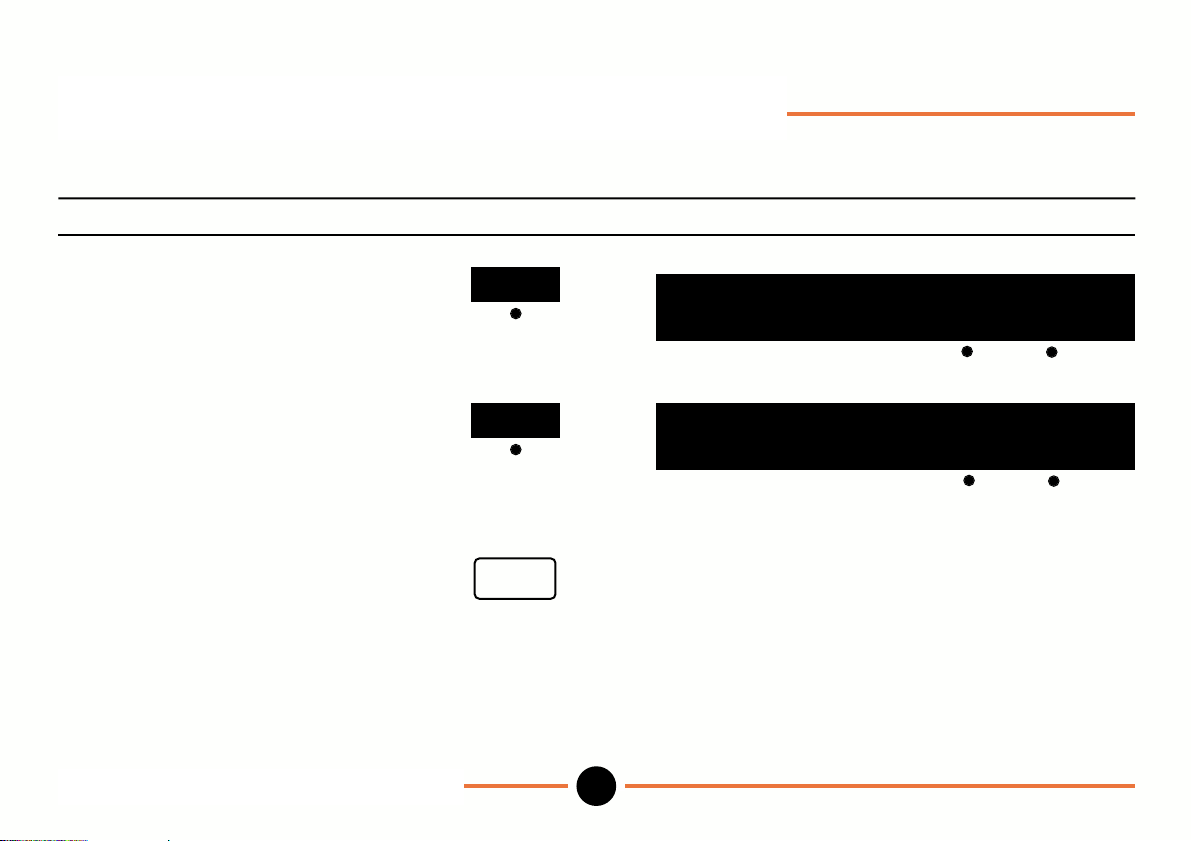
Operation mode: Preset (continued)
To switch between absolute and incremental datum.
Operation Key stroke Display
To switch to absolute datum.
Toggle to abs.
To switch to incremental datum.
Toggle back to inc.
To return to main
operation menu.
Operation mode: Preset (continued)
DR601
inc
abs
escape
88.8888
pst 12.3456 abs load
12.3456
pst 12.3456 inc load
10
M-3344 02/99
Page 13
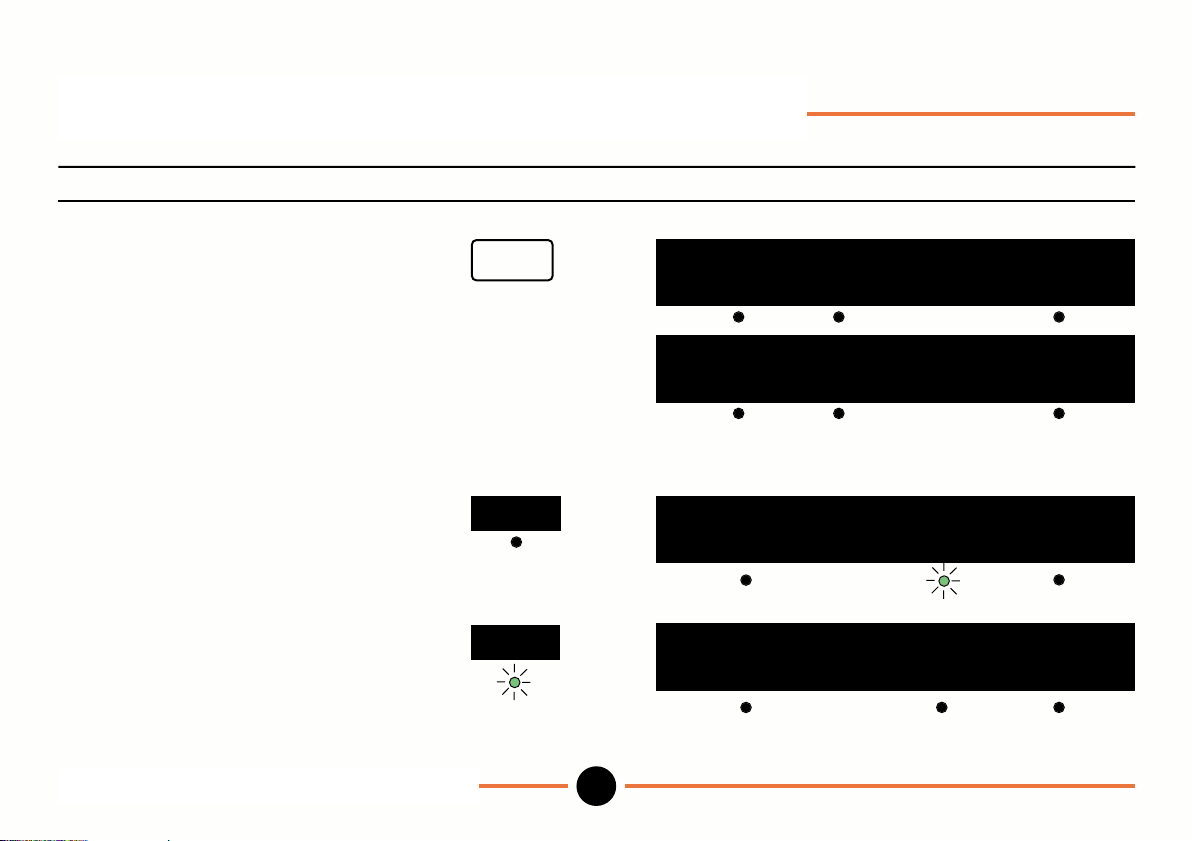
Operation mode: Maximum/Minimum
To use maximum/minimum with zero and preset datum proceed as follows:
Operation Key stroke Display
To establish zero datum.
press zero.
or
To establish preset datum .
(e.g. 28.000) key in and load
preset using preset routine.
Then escape.
To select max/min.
Press mx/mn.
To clear the register.
IMPORTANT: Do not press
the reset key until you are
ready to start taking readings.
Operation mode: Maximum/Minimum
DR601
zero
mx/mn
reset
0.0000
preset mx/mn mm
28.0000
preset mx/mn mm
88.8888
actual reset load
88.8888
actual reset load
11
M-3344 02/99
Page 14
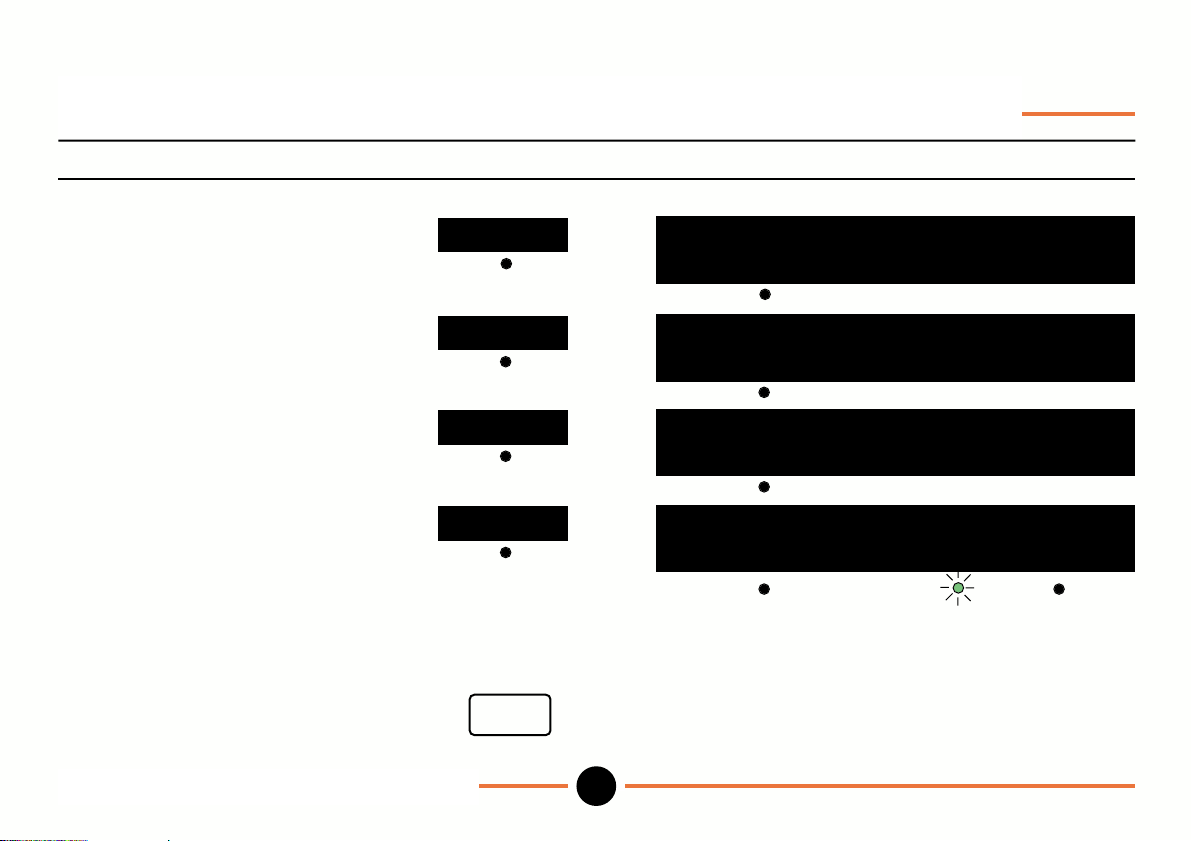
Operation mode: Maximum/Minimum (continued)
Operation Key stroke Display
To view maximum
toggle to maximum.
To view minimum
toggle to minimum.
To view difference
toggle to difference.
To get ready for next test
toggle to actual.
Note:
To confirm zero datum press zero key when actual lamp is lit.
or
To confirm preset datum press load when actual lamp is lit.
To return to main Operation menu.
Operation mode: Maximum/Minimum
DR601
actual
maximum
minimum
difference
escape
12
88.8888
maximum
88.8888
minimum
88.8888
difference
88.8888
actual reset load
M-3344 02/99
Page 15
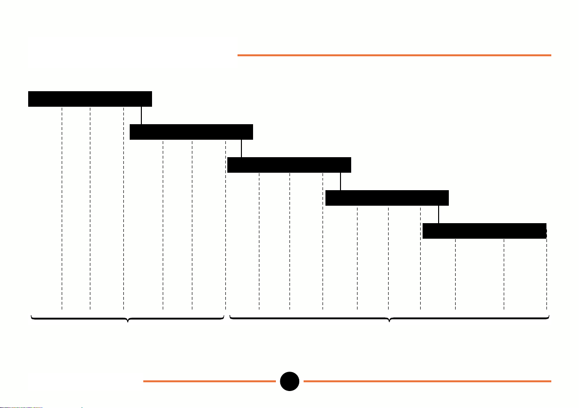
Setup mode: Menus
Workshop setup
preset limit probe more
Probe related setup
x.xxx dir ref more
Configuration
show units prog more
Inputs & outputs
print RS232 ext more
Security & default
lock pass_wd default
preset limits probes resolution direction reference show units program print RS232 external lock password defaults
all programs system setup (standard program only)
Setup mode: Menus
DR601
13
M-3344 02/99
Page 16
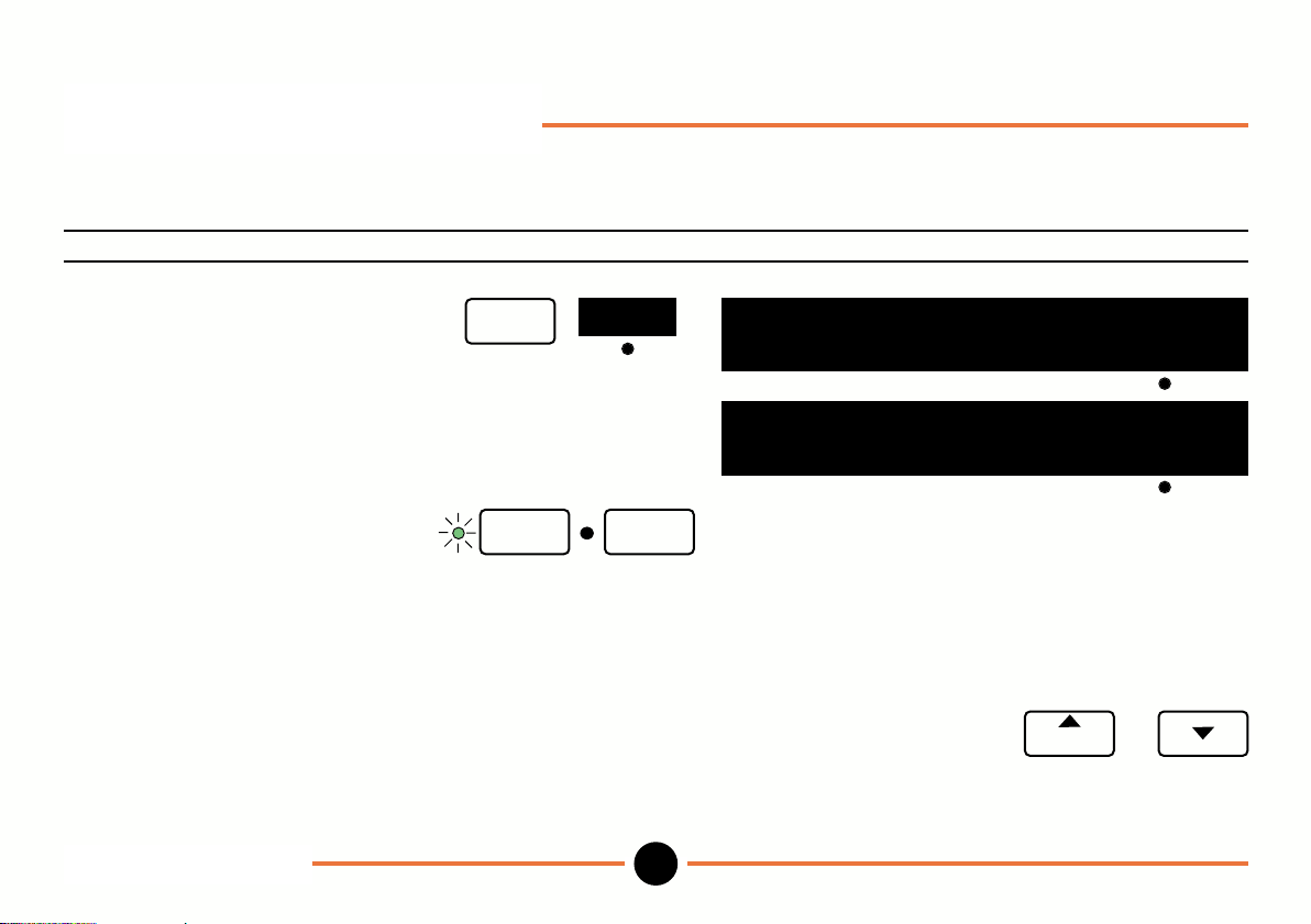
Setup mode: Preset
(Allows you to store presets for each of the ten programs and to copy and store presets from master components).
To store a preset in the standard program proceed as follows:
Operation Key stroke Display
keys
preset
14
88.8888
pst zz.
pst 12.3456 del
zz zz zz zz
copy
program
M-3344 02/99
To select preset menu
in Setup mode.
To key in preset (e.g. 12.3456). use numeric
To store preset and return
to Operation mode.
Notes: 1. To load preset into numeric display and establish preset datum go to Operation mode preset or max/min
menu and press load key.
2. To enter and store presets for programs 1 to 9 select required program number using or
keys and repeat above procedure.
setup
enter setup
Setup mode: Preset
DR601
Page 17
Setup mode: Preset (continued)
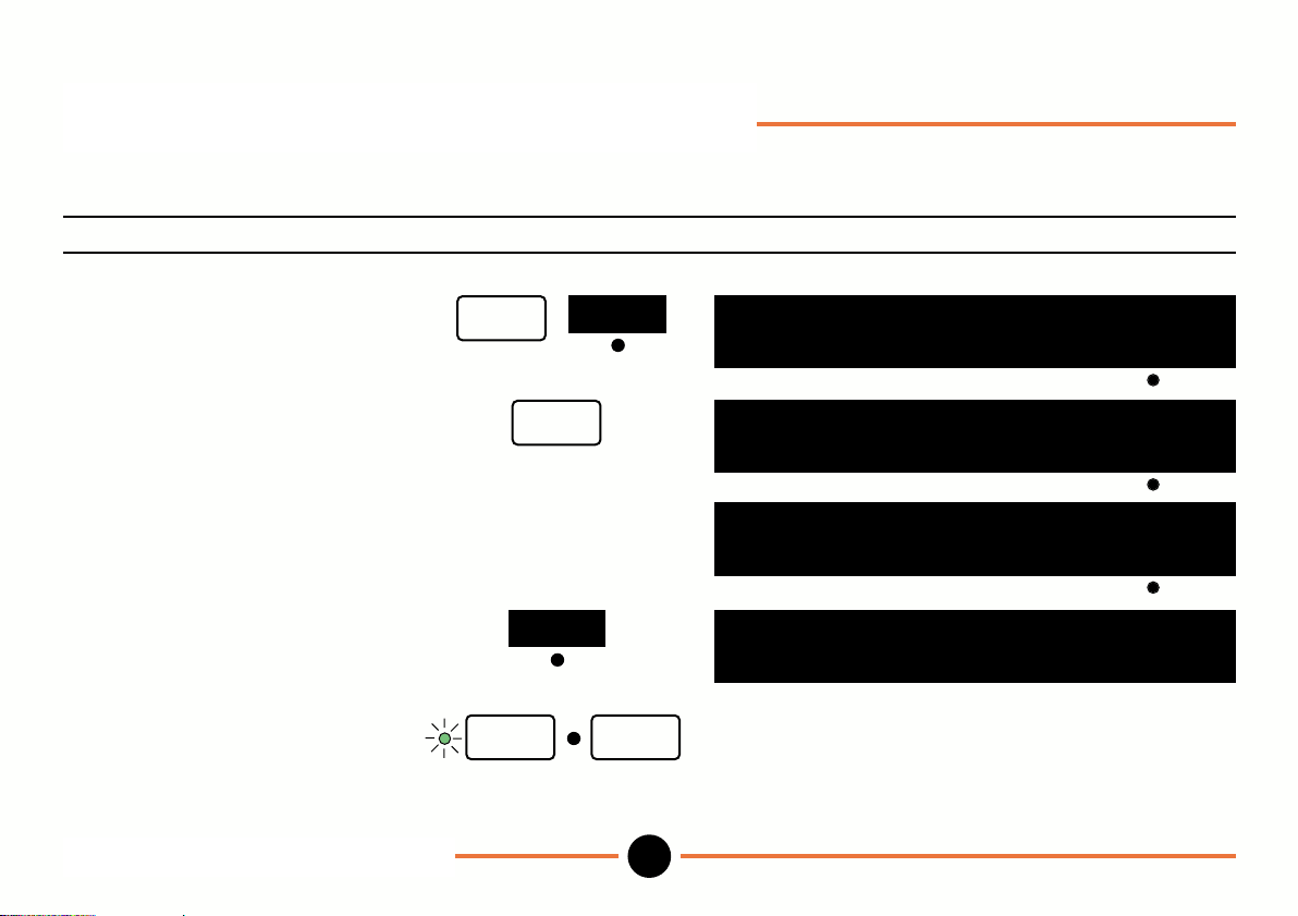
To copy a preset from a master component proceed as follows:
Operation Key stroke Display
To select preset menu
in Setup mode.
Establish datum
press zero.
Measure part (e.g. 1.010).
To copy reading to preset.
To store a preset and
return to Operation menu.
Setup mode: Preset (continued)
DR601
setup
enter
zero
copy
preset
setup
15
88.8888
pst zz.
zz zz zz zz
0.0000
pst zz.
zz zz zz zz
1.010
pst zz.
zz zz zz zz
1.010
pst 1.010
copy
copy
copy
M-3344 02/99
Page 18
Setup mode: Preset (continued)
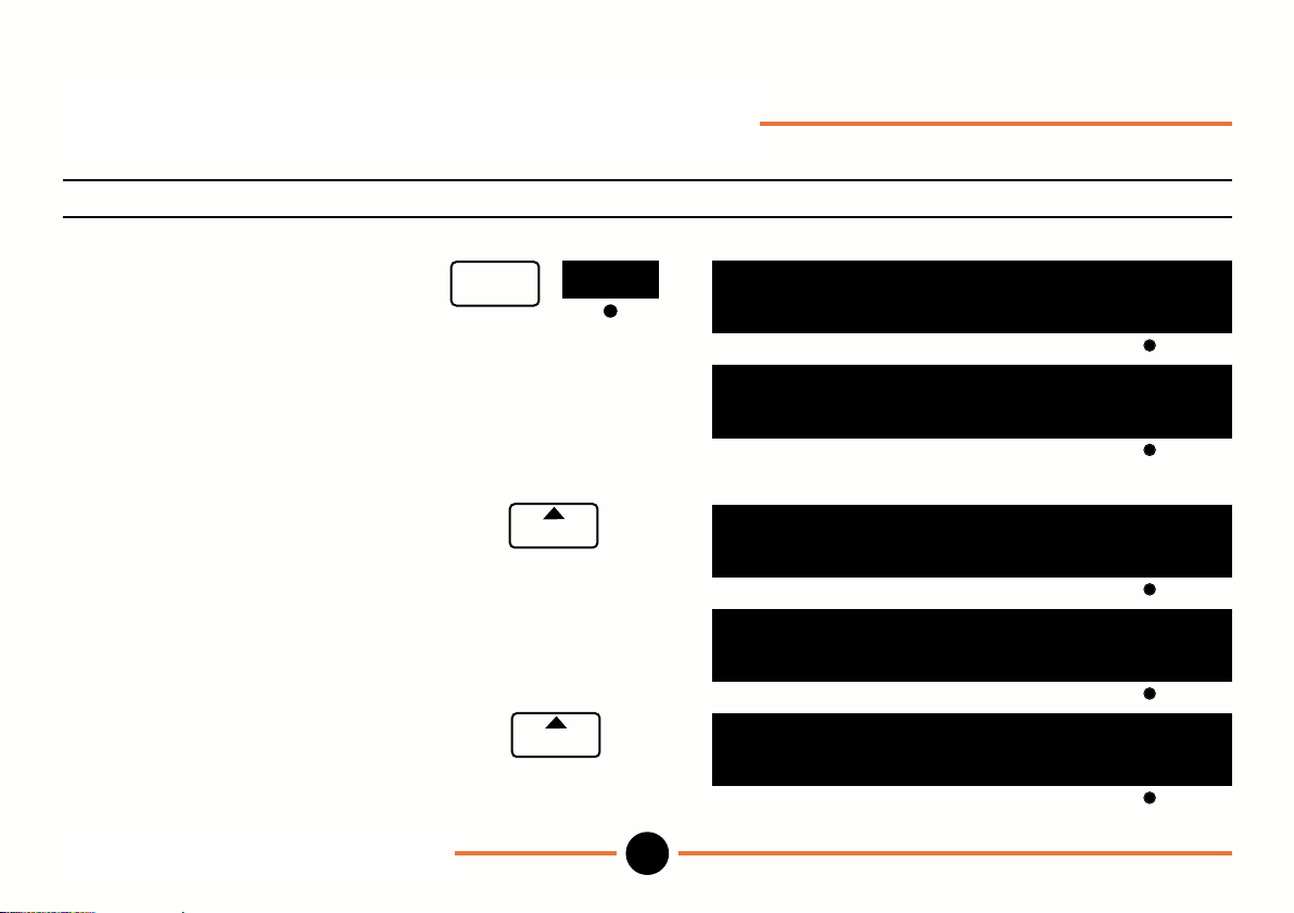
To store and use presets for up to 10 programs with one probe (or pair of probes e.g. A+B) and one datum.
Operation Key stroke Display
To select preset menu in
Setup mode.
To key in preset (e.g. 0) use numeric
for standard program. keys
To store preset and move to program 1.
To key in preset (e.g. 1) use numeric
for program 1. keys
To store preset and move to program 2.
Continue as above for remaining programs.
setup
preset
program
program
Setup mode: Preset (continued)
DR601
16
Prog
88.8888
pst zz.
Prog
pst 0 del
Prog
1
pst zz.
Prog
1
pst 1 del
Prog
2
pst zz.
zz zz zz zz
88.8888
zz zz zz zz
88.8888
zz zz zz zz
copy
copy
copy
M-3344 02/99
Page 19
Setup mode: Preset (continued)
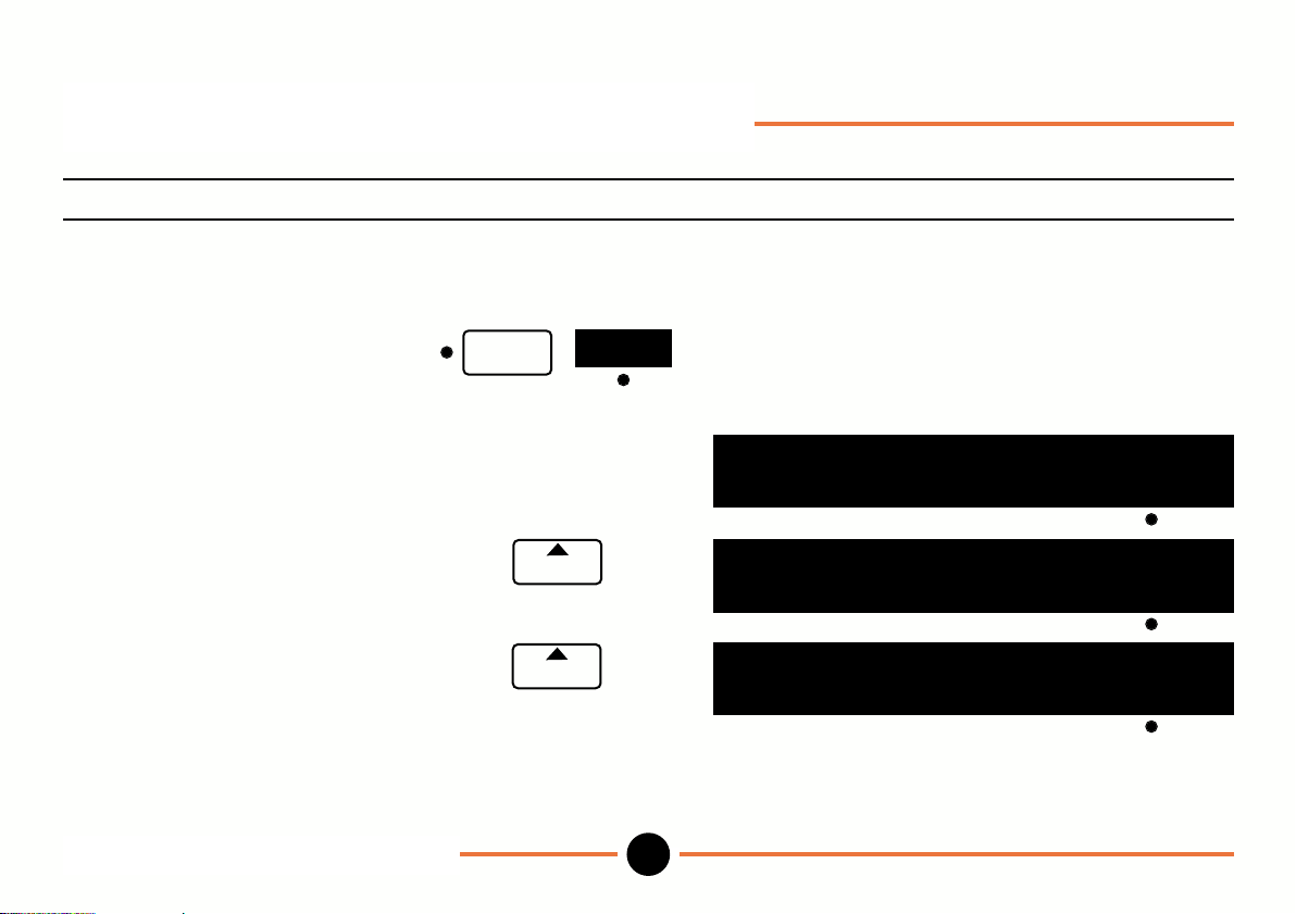
Operation Key stroke Display
To view presets in Operation mode.
To return to Operation mode preset
press setup and preset.
Display shows preset value stored
in the standard program.
To view program 1 preset.
To view program 2 preset.
Setup mode: Preset (continued)
DR601
setup
program
program
preset
17
Prog
88.8888
pst 0.0000 abs load
Prog
1
pst 1.0000 abs load
Prog
2
pst zz.
88.8888
88.8888
zz zz zz zz
abs load
M-3344 02/99
Page 20
Setup mode: Preset (continued)
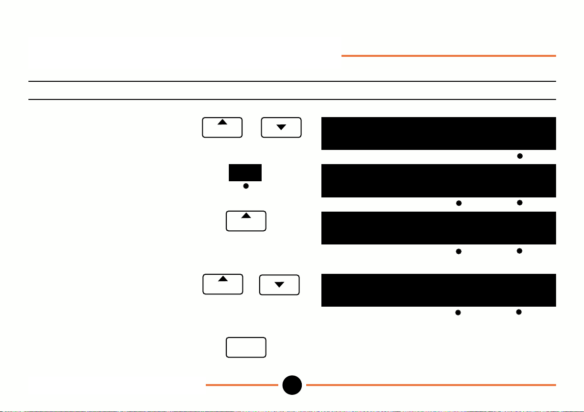
Operation Key stroke Display
To load a preset and establish preset datum
Select standard program. or
program
Prog
88.8888
pst 0.0000 abs load
Press load key.
To view preset 1 and
reading with respect to
preset datum.
To view other presets and or
readings with respect to
preset datum.
To return to main
Operation menu.
load
program
program
escape
Setup mode: Preset (continued)
DR601
18
Prog
0.0000
pst 0.0000 inc load
Prog
1
pst 1.0000 inc load
Prog
zz
pst zz.
1.0000
88.8888
zz zz zz zz
inc load
M-3344 02/99
Page 21
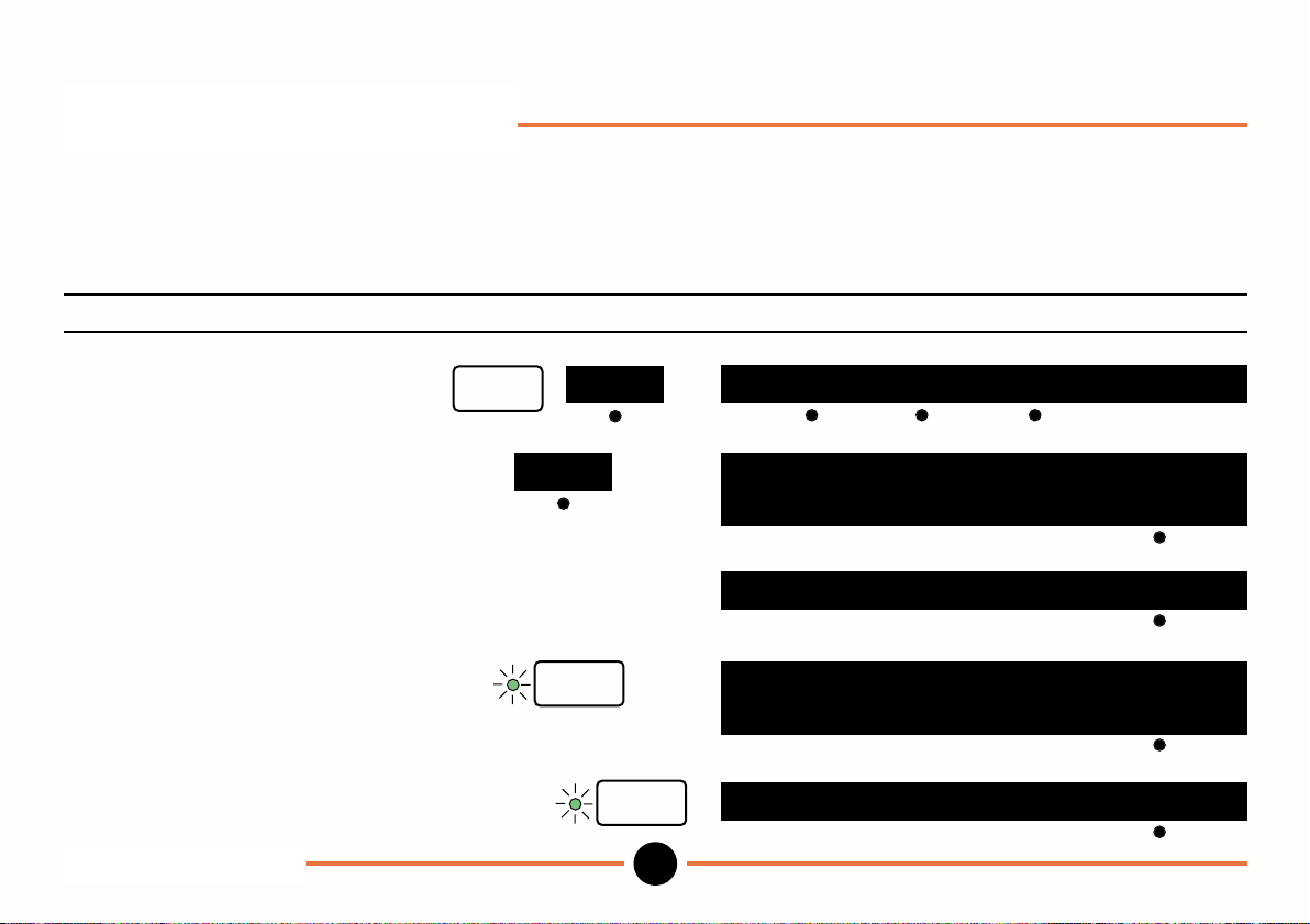
Setup mode: Limits
(Allows you to store limits to control the range lamps for each of the 10 programs. Upper and lower limits may be
entered directly or by keying in the the nominal plus high and low tolerances. Limits may be copied from master
components and range lamps can be enabled or inhibited).
To store upper and lower limits and control whether range lamps are enabled or inhibited.
Operation Key stroke Display
To select limits menu.
To enter upper and lower limits
choose limit option.
To enter upper limit (e.g. 0.01). use numeric
To store upper limit.
To enter and store lower limit use numeric
(e.g. -0.01). keys
setup
limit
limit
keys
enter
Setup mode: Limits
DR601
enter
19
limit nom+tol mx/mn
88.8888
hi limit = zz.
hi limit = 0.01 del
zz zz zz zz
copy
88.8888
lo limit = zz.
range lamps on? no
zz zz zz zz
copy
M-3344 02/99
Page 22
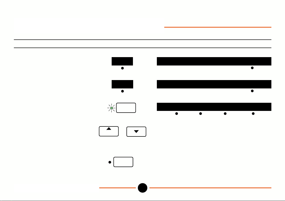
Setup mode: Limits (continued)
Operation Key stroke Display
To turn range lamps on,
toggle to yes
or
To turn range lamps off
toggle to no.
no
yes range lamps on? no
enter
To complete press enter.
To enter and store limits for or
programs 1 to 9, select program
number and repeat above procedure.
program
setup
To return to operating mode.
Setup mode: Limits (continued)
DR601
range lamps on? yes
preset limit probe more
20
M-3344 02/99
Page 23
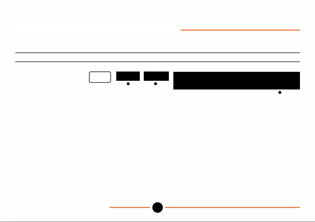
Setup mode: Limits (continued)
To enter and store limits for the standard program using nominal and tolerance.
Operation Key stroke Display
To select nominal and
tolerance method of
entering limits.
Enter nominal, then proceed
as instructed.
setup
Setup mode: Limits (continued)
DR601
limit
nom+tol
21
88.8888
nominal = zz.
zz zz zz zz
copy
M-3344 02/99
Page 24
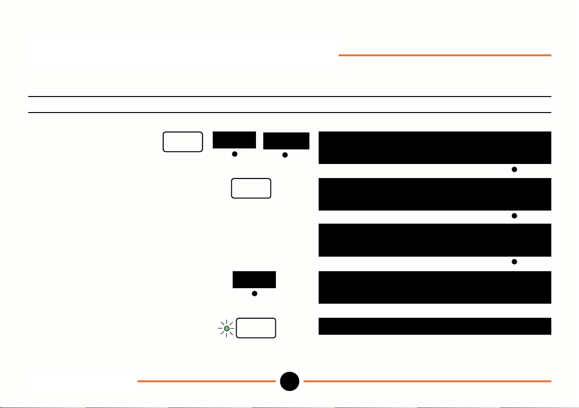
Setup mode: Limits (continued)
To copy the nominal from a master component.
Operation Key stroke Display
Select nominal + tolerance.
Establish datum and press zero.
Measure part (e.g. 1.010).
To copy reading to nominal.
To save nominal.
Proceed as instructed.
Setup mode: Limits
DR601
setup
limit
copy
zero
enter
nom+tol
22
88.8888
nominal = zz.
zz zz zz zz
0.0000
nominal = zz.
zz zz zz zz
1.0100
nominal = zz.
zz zz zz zz
1.0100
nominal = 1.0100
hi tol = zz.
zz zz zz zz
copy
copy
copy
M-3344 02/99
Page 25
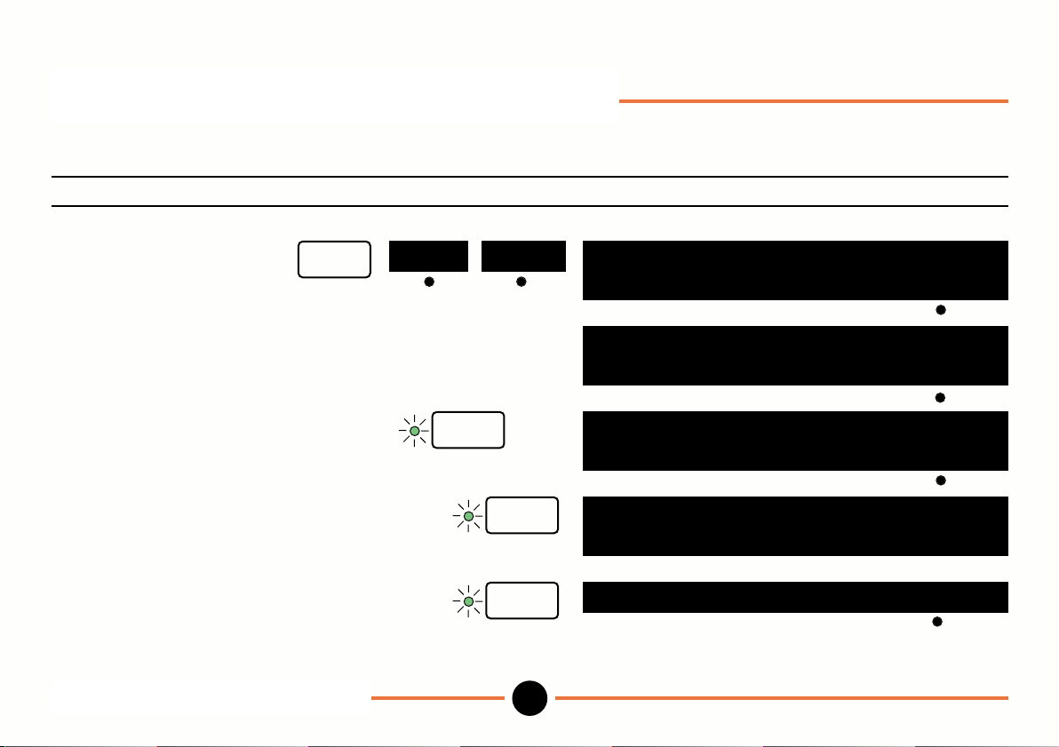
Setup mode: Limits (continued)
To store upper, lower and difference limits for use in maximum/minimum Operation menu.
Operation Key stroke Display
To select maximum/
minimum/difference
limits.
To enter upper limit (e.g. 0.01). use numeric keys
To store upper limit.
To enter and store lower limit use numeric
(e.g. -0.01). keys
To enter and store difference limit use numeric
(e.g. 0.015). keys
Proceed as instructed.
setup
limit
mx/mn
enter
enter
enter
Setup mode: Limits (continued)
DR601
23
88.8888
hi limit = zz.
hi limit = 0.01 del
zz zz zz zz
copy
88.8888
lo limit = zz.
diff lmt = zz.
range lamps on? no
zz zz zz zz
zz zz zz zz
copy
M-3344 02/99
Page 26
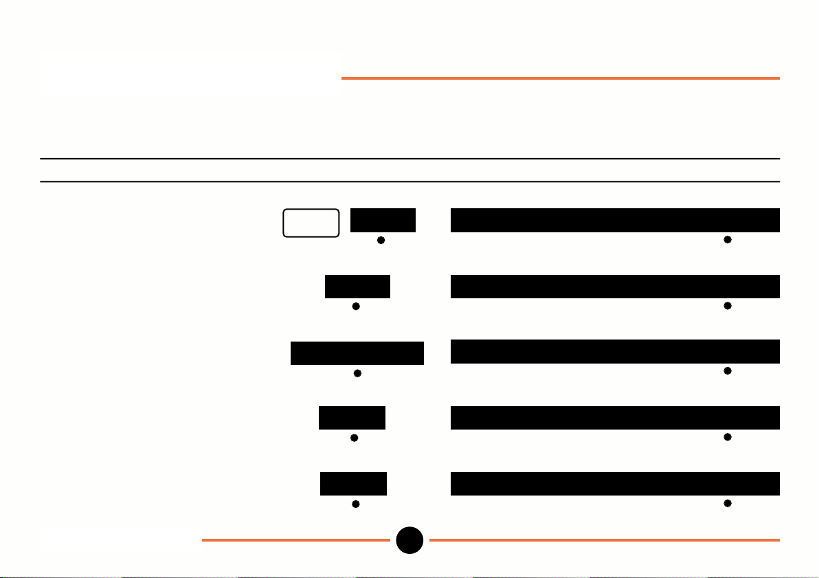
Setup mode: Probes
(Allows you to set up individual probes, pairs of probes (A + B or A - B); to assign probes to programs and to set up a
group of probes that can be scanned).
To select individual probe, A+B, A-B, or scan.
Operation Key stroke Display
To select probe menu.
To set up a single probe toggle
through choices to individual probe.
To set up 2 probes in an A + B
configuration toggle to A + B.
To set up 2 probes in an A - B
configuration toggle to A - B.
To setup, up to 30 probes to be
scanned toggle to scan.
Setup mode: Probes
DR601
setup
individual probe
probe
scan use: individual probe
24
use: individual probe
use: A+B
use: A-BA+B
use: scanA-B
M-3344 02/99
Page 27
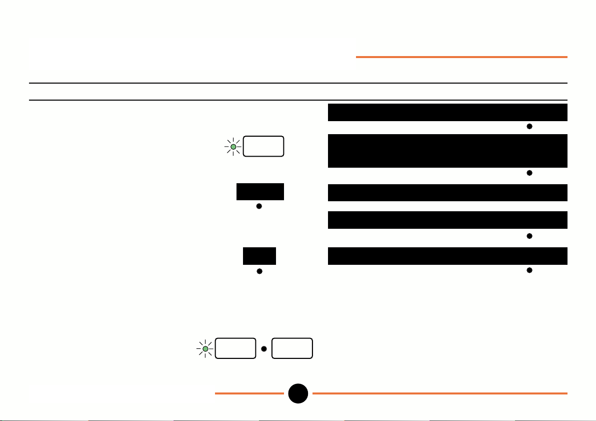
Setup mode: Probes (continued)
To install a new probe for use with all programs.
Operation Key stroke Display
Select individual probe as previous page.
use : individual probe
To identify current probe.
To specify a new probe,
select new.
move probe tip
To use this probe with all
programs toggle to yes
Note:- This option is only
available in the standard
program.
To complete.
Note: Procedure for A+B and A-B configurations is similar to the above.
Setup mode: Probes (continued)
DR601
enter
enter
new
move probe tip
copy to all progs no
copy to all progs yesno
setup
25
ID=
88.8888
zz zz zz zz zz zz zz zz zz zz
new
*
M-3344 02/99
Page 28
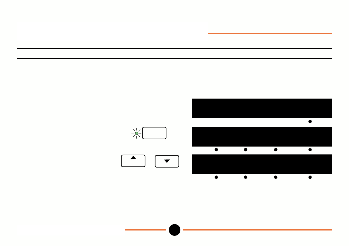
Setup mode: Probes (continued)
To install different probes for use in each program.
Operation Key stroke Display
To install first probe in standard
program proceed as for last section
until prompted to press probe tip. move probe tip
Prog
copy to all progs ? no
Press enter key (i.e. do not
copy to all programs).
enter
Select program number 1 to 9 or
and repeat above procedure.
program
Procedure for A+B and A-B
configuration is similar to the above.
Setup mode: Probes (continued)
DR601
26
Prog
preset limit probe more
Prog
1
preset limit probe more
M-3344 02/99
Page 29
Setup mode: Probes (continued)
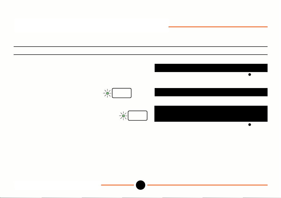
To scan through a group of probes.
Operation Key stroke Display
Select scan from
Probe use choices.
To select number of probes
to be scanned.
Select number (e.g. 10). use numeric
keys
Select new and proceed
as instructed to select
remaining probes.
Setup mode: Probes (continued)
DR601
enter
enter
27
use : scan
scan probes : 30
88.8888
zz zz zz zz zz zz zz zz zz zz
I=
new
M-3344 02/99
Page 30
Setup mode: Probes (continued)
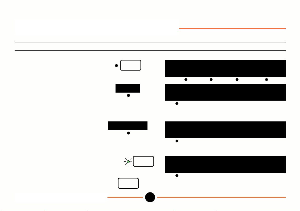
To use scan in Operation mode.
Operation Key stroke Display
To return to Operation mode
press setup.
To select scan and view
probe 1 reading press scan.
To view probe 2 reading
toggle to scan probe 2
or
Key in 2 and press enter.
use numeric
To return to main Operation menu.
Setup mode: Probes (continued)
DR601
setup
scan
scan probe 1
keys
escape
enter
28
88.8888
preset mx/mn scan mm
88.8888
scan probe 1
88.8888
scan probe 2
88.8888
scan probe 2
M-3344 02/99
Page 31
Setup mode: Resolution
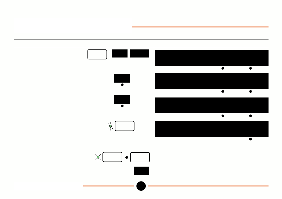
To change the displayed resolution for a probe.
Operation Key stroke Display
To select resolution menu.
setup
more
X.XXX
1.2345
no of digits: less more
more
enter
less
enter
1.234
no of digits: less more
1.234
no of digits: less more
1.2345
step size: 1
setup
more
29
M-3344 02/99
To decrease number of full
decades displayed.
To increase decades displayed.
To select resolution of 1, 2 or 5
in the last decade.
Toggle to 1, 2 or 5 as required.
To complete and return to
Operation mode.
Note: When full resolution of probe has been reached choice will disappear and only valid step sizes will be
available.
Setup mode: Resolution
DR601
Page 32
Setup mode: Direction
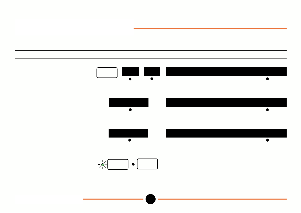
To change the direction of count.
Operation Key stroke Display
To select direction menu.
For increasing count as probe
extends toggle to extend=+.
For increasing count as probe
retracts toggle to retract=+.
To complete and return to
Operation mode.
Setup mode: Direction
DR601
setup
more dir
retract = +
enter
direction: retract = +
direction: extend = +
direction: retract = +extend = +
setup
30
M-3344 02/99
Page 33
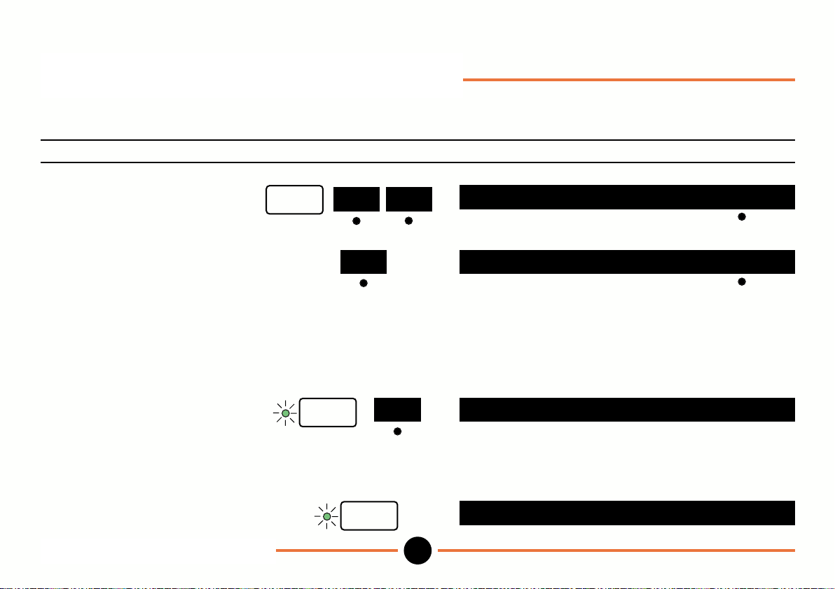
Setup mode: Reference Mark
Uses reference marker on the Linear Encoder to establish reference datum.
Operation Key stroke Display
To select reference menu.
To turn reference mode on
toggle to on.
In this mode Linear Encoder tip
must be moved so that reference
marker is passed each time Readout
is powered up.
To select reference datum.
Press enter and select new.
Establish machine datum.
Press enter.
Setup mode: Reference Mark
DR601
setup
more
off ref mode : on
enter
ref
new set machine datum
enter
ref mode : off
datum :
zz zz.zz zz zz
31
M-3344 02/99
Page 34
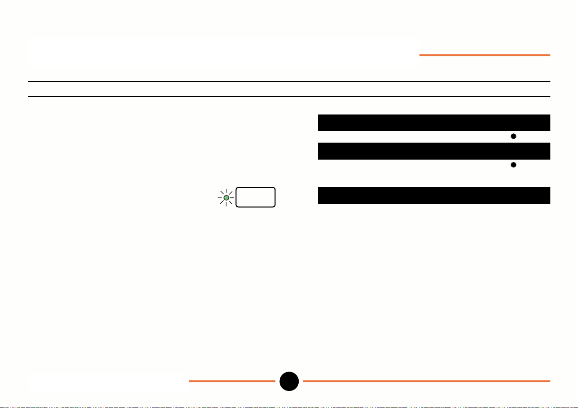
Setup mode: Reference Mark (continued)
Operation Key stroke Display
For zero datum key in 0 Key in 0
or
For a preset datum (eg 10.5) Use numeric
key in 10.5. keys
Press enter.
Move tip until display counts.
Note: Reference lamp is on when in reference mode.
enter
Setup mode: Reference Mark
DR601
datum = 0 del
datum = 10.5 del
move thru ref mark
32
M-3344 02/99
Page 35
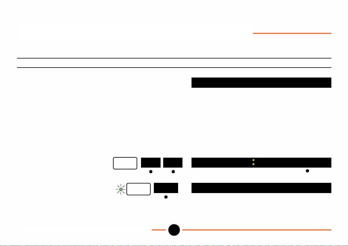
Setup mode: Reference Mark (continued)
To Recall reference mark.
Operation Key stroke Display
Recall after power down.
Power on.
Move tip until display counts.
Recall reference mark with unit powered up.
move thru ref mark
To select reference menu.
Press enter and recall.
Move tip until display counts.
setup
more ref
enter
Setup mode: Reference Mark (continued)
DR601
ref mode on
recall move thru ref mark
33
M-3344 02/99
Page 36
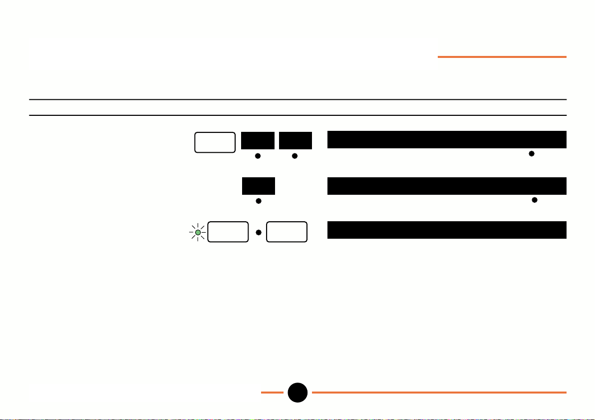
Set up mode: Reference Mark (continued)
To switch off reference mode.
Operation Key stroke Display
To select reference menu.
Toggle to off.
To complete and return to
Operation mode.
setup
more ref
enter setup
Setup mode: Reference Mark (continued)
DR601
on
ref mode = on
ref mode = off
press zero to continue
34
M-3344 02/99
Page 37
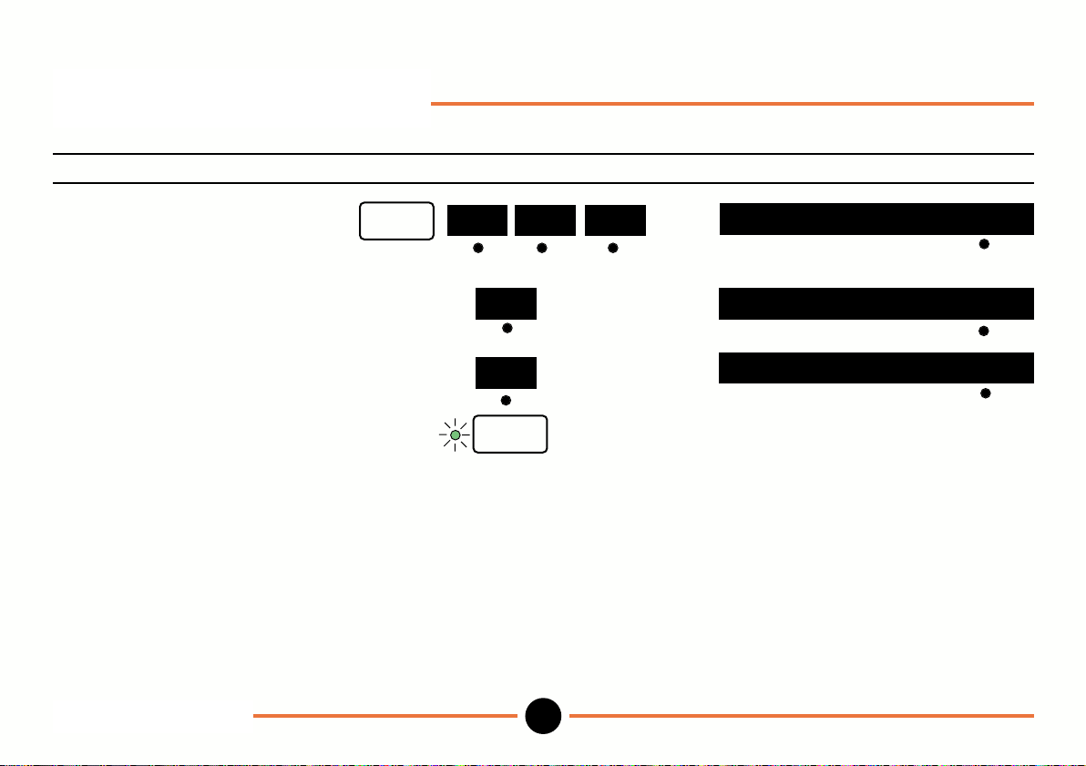
Setup mode: Show
To show or hide operation menus.
Operation Key stroke Display
To select show menu.
Toggle to yes to show the
menu in Operation mode.
Toggle to no to hide the menu.
Press enter to save the change
and move onto the next selection.
Proceed as instructed.
Note: To show scan in Operation menu first install probes to be scanned using setup probe menu.
setup
more
Setup mode: Show
DR601
more show
no
yes
enter
35
show preset ? yes
show preset ? yes
show preset ? no
M-3344 02/99
Page 38
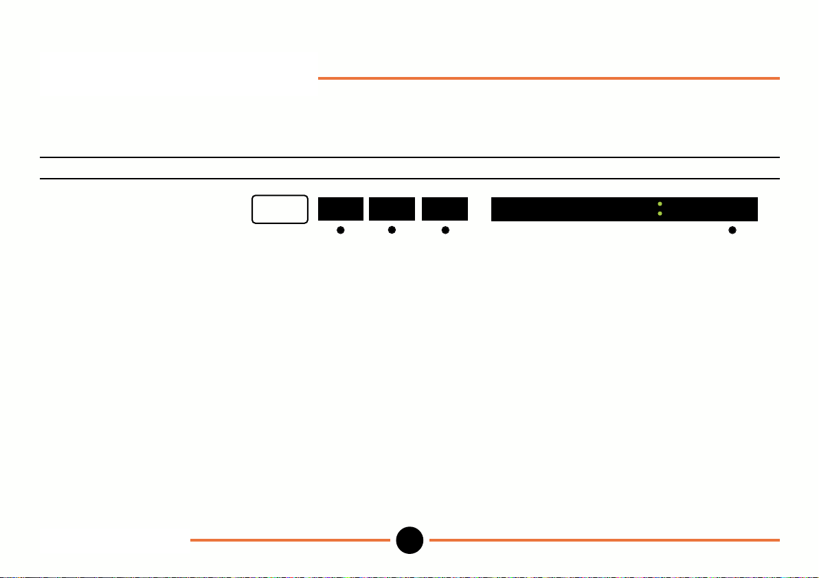
Setup mode: Units
(Allows you to select inches or mms, to show or hide the units in operation mode and to enable the units shown in
operation mode to be changed).
Operation Key stroke Display
To select units menu. unit of measure =
Proceed as instructed.
setup
more
Setup mode: Units
DR601
more units
36
unit of measure mm
M-3344 02/99
Page 39
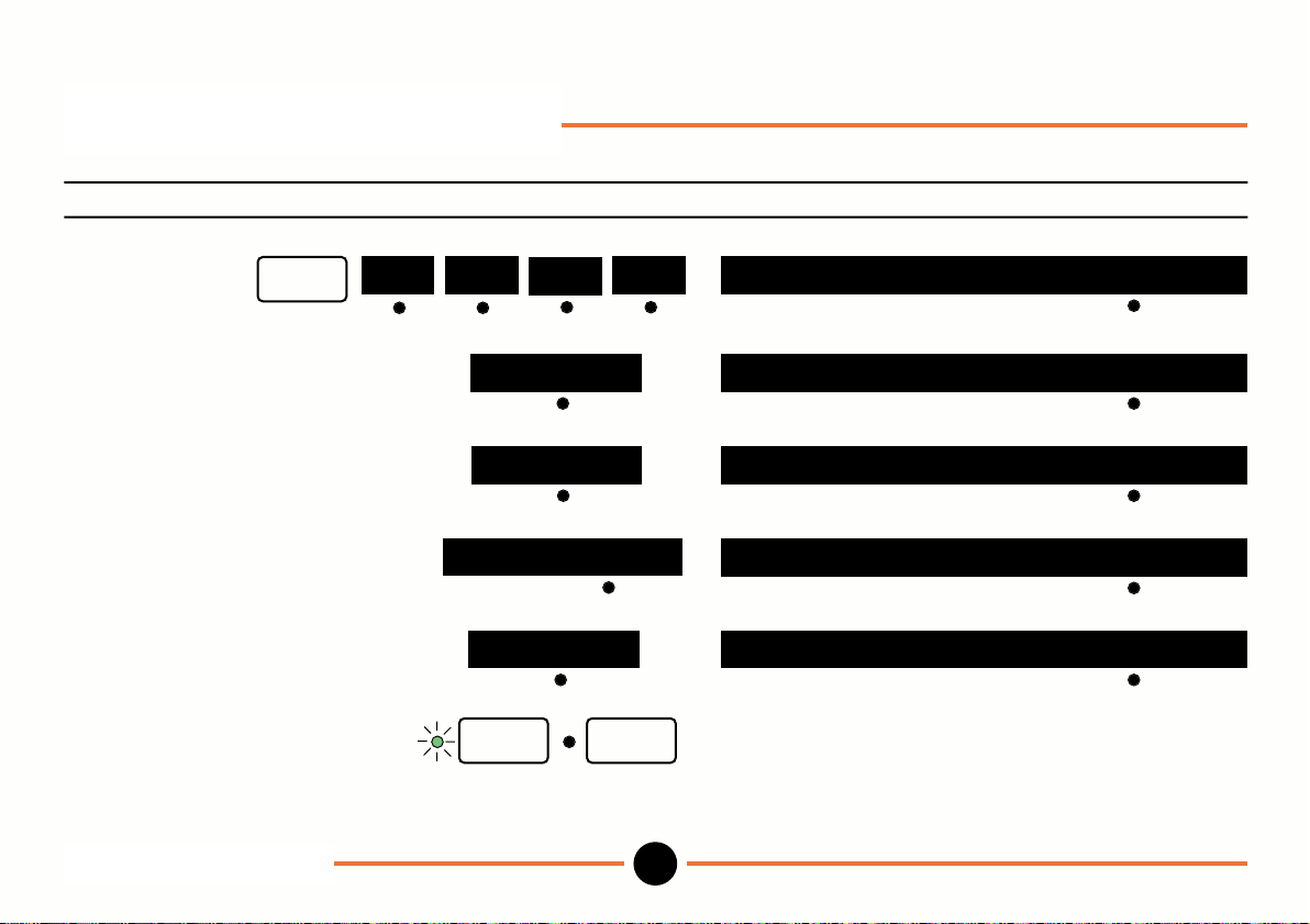
Setup mode: External
To freeze display with external signal or RS232 CTRL B character.
Operation Key stroke Display
To select external menu.
setup
To freeze on RS232 command
toggle to RS232.
To freeze on negative edge of external
signal toggle to remote neg edge.
To freeze when remote signal
is low, toggle to remote low.
To switch off freeze facility,
toggle to no freeze.
To complete and return to
Operation mode.
Note: See Digital Benchtop Meter Installation Manual for electrical specification and timing for remote signals.
more more
remote neg edge
more
no freeze
RS232
enter
Setup mode: External
DR601
ext
setup
37
freeze: no freeze
freeze: RS232
freeze: remote neg edge
freeze: remote low
freeze: no freezeremote low
M-3344 02/99
Page 40
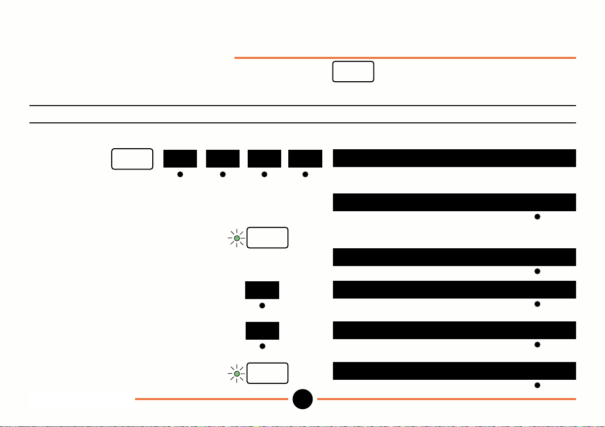
Setup mode: Print
(Determines what information is sent to a printer or PC when the key is pressed or a send measurement
command is received on the RS 232 interface, in operation mode).
To configure print options.
Operation Key stroke Display
To select print menu.
setup
To key in number of blank lines use numeric
on print out e.g. 5. keys
Press enter.
To print the program number
toggle to yes
or
To print reading without program
number toggle to no.
more
more more
enter
no
yes
print
print
blank lines: 0
blank lines: 5 del
print program no.? no
print program no.? yes
print program no.? no
Press enter.
Setup mode: Print
DR601
enter
print: this reading
38
M-3344 02/99
Page 41
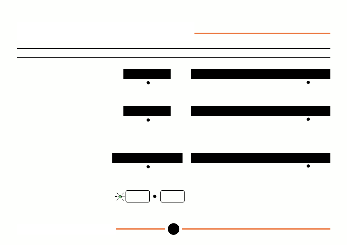
Setup mode: Print (continued)
Operation Key stroke Display
To print the current reading only
toggle through choices to
this reading.
To print the reading and move
onto next selection, toggle through
choices to reading then step
(see Note 1 on following page).
To print all readings toggle
through choices to all readings
(see Note 2 on following page).
To complete &
return to Operation mode.
Setup mode: Print (continued)
DR601
all readings
this reading
reading then step
enter setup
39
print: this reading
print: reading then step
print: all readings
M-3344 02/99
Page 42
Setup mode: Print (continued)
Operation Key stroke Display
Note1:
When max/min menu is selected in Operation mode displayed reading (e.g. maximum) is printed then next reading
(e.g. minimum) is displayed. When scan menu is selected in operation mode displayed reading (e.g. scan 5) is
printed then reading for next probe (e.g. scan 6) is displayed.
If max/min or scan are not selected reading for current program (e.g. prog 2) is printed then reading for next program
(e.g. prog 3) is displayed.
Note 2:
When max/min menu is selected maximum, minimum and difference readings are all printed.
When scan menu is selected readings for all scanned probes are printed. If max/min and scan are not selected
readings for all programs are printed.
Setup mode: Print (continued)
DR601
40
M-3344 02/99
Page 43
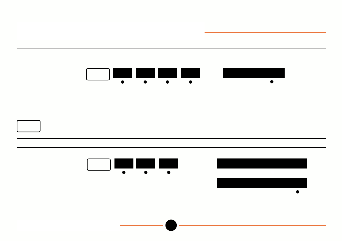
Set up mode: RS232 & Program
RS232: To configure RS232 serial port for connection to a printer or PC.
Operation Key stroke Display
To select RS232:
Proceed as instructed.
Program: To select the number of programs required and whether to return to the standard program each time
setup
Operation Key stroke Display
To select program.
To change number of programs
key in last program use numeric
number e.g. 5 (must be keys
in range 1 to 9).
is pressed.
setup
setup
Setup mode: RS232 & Program
DR601
more
more
more more RS232 baud rate: 9600
more prog
last program no: 9
last program no: 5 del
41
M-3344 02/99
Page 44
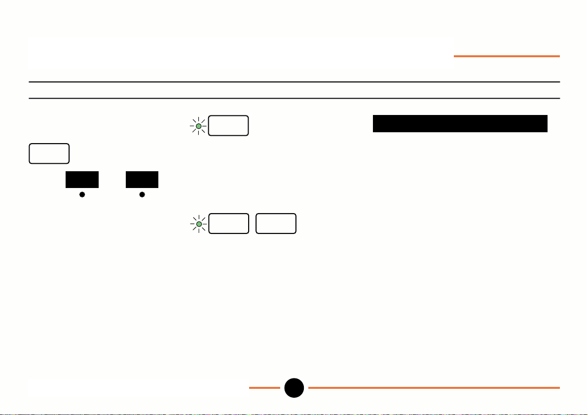
Set up mode: RS232 & Program (continued)
Operation Key stroke Display
To select whether to return to
the standard program each time
setup
Select or as appropriate
To save settings and return to
operation mode.
Setup mode: RS232 & Program (continued)
DR601
is pressed
noyes
enter
enter setup
default to std prog? yes
42
M-3344 02/99
Page 45
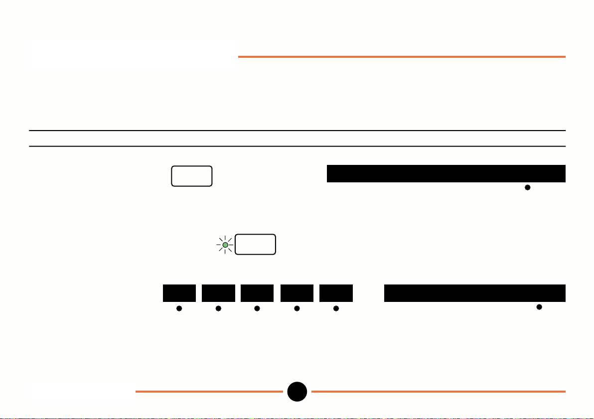
Setup mode: Lock
(Allows you to lock individual Operation mode keys and Setup menus. Locked keys and menus may only be accessed
when correct password has been entered. Lock, password and default menus are always locked until correct password
has been entered).
Operation Key stroke Display
To enter password use numeric keys
press setup and key in
password (factory
default is 0000).
press enter.
To select lock menu
Select yes for lock to
become live when setup
key is pressed to go back
to Operation mode.
Set up mode: Lock
DR601
setup
enter
more more more more lock lock active ? yes
43
password: 0000 del
M-3344 02/99
Page 46
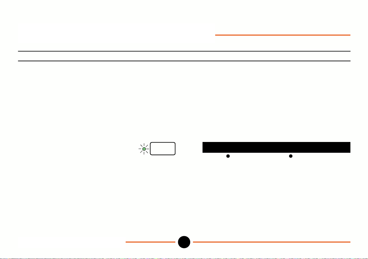
Setup mode: Lock (continued)
Operation Key stroke Display
Toggle to no if you wish
to move between setup
mode and Operation mode
without activating locked keys
and menus (note: locks are
always active after power up).
Press enter.
Select operate to lock or unlock
Operation mode keys; or setup
to lock or unlock setup menus.
Proceed as instructed.
Set up mode: Lock (continued)
DR601
enter
operate setup
44
M-3344 02/99
Page 47
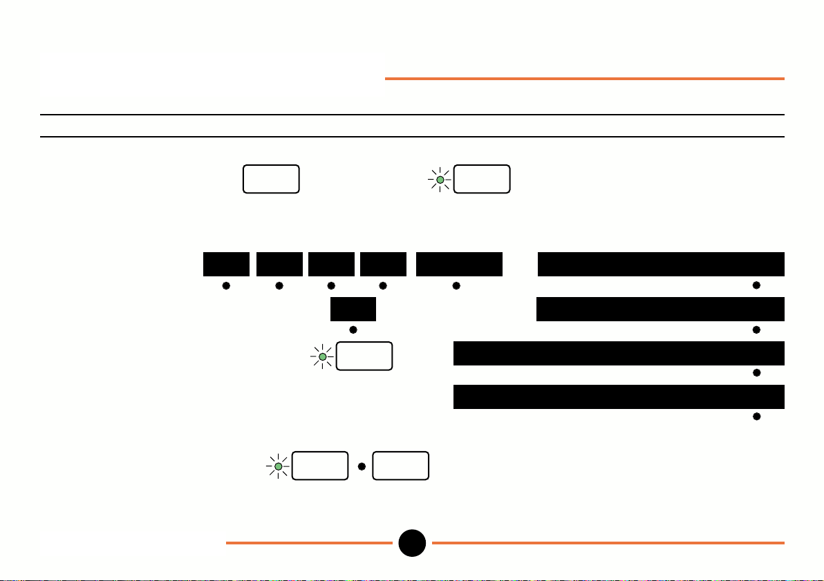
Setup mode: Password
To change the password.
Operation Key stroke Display
To enter existing password use numeric keys
press setup and key in
password (factory default is 0000).
Select password menu
Toggle to yes.
more more more more pass_wd
setup
no
enter
Press enter.
Key in new password use numeric
(e.g. 9999). keys
enter setup
To complete.
Setup mode: Password
DR601
45
enter
change password? no
change password? yes
new password: del
new password:9999 del
M-3344 02/99
Page 48
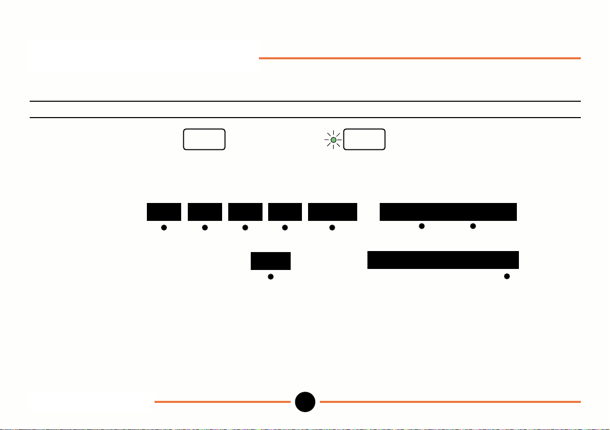
Setup menu: Default
To recall factory defaults.
Operation Key stroke Display
To enter password use numeric keys
press setup and key in
password (factory default is 0000).
To select default.
Select recall.
Proceed as instructed.
Note:
New option above overwrites factory default settings with the current settings. An additional security code is required
to use this option. Consult your Omega dealer for further information.
Set up mode: Default
DR601
setup enter
moremore more more default
recall
46
recall new
clear all settings ? no
M-3344 02/99
Page 49
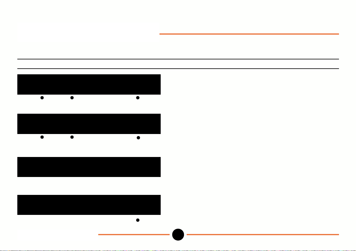
Errors: Error Messages
Display Error Action
- - - - - - - - - -
preset mx/mn mm
- - - - - - - - - -
preset mx/mn mm
eee eee eee
preset mx/mn mm
probe is missing new
Errors: Error messages
DR601
Digital Probe over range. Reposition probe within
measuring range.
Digital Probe under range. Reposition probe within
measuring range.
Displayed number outside Use smaller preset value.
allowable range
(±999.999 99mm or 39.370078 inch).
Probe not connected Switch off unit. Connect probe.
Probe has been changed Select new, then proceed.
as instructed.
47
M-3344 02/99
Page 50
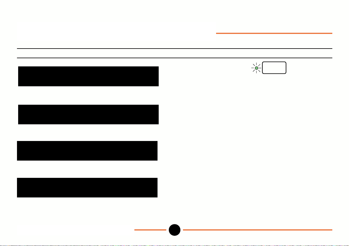
Errors: Error Messages (continued)
Display Error Action
**overspeed error**
Ç alternating with Ê
zz zz zz zz zz zz zz zz zz zz
ID=
**probe fault** code:
zz zz zz zz
Ç alternating with Ê
zz zz zz zz zz zz zz zz zz zz
ID=
Errors: Error messages (continued)
DR601
Overspeed error
(Tip of Linear Encoder Then proceed as instructed .
has been moved too fast).
Probe fault. Record error code.
48
enter
Consult your Omega Dealer.
M-3344 02/99
Page 51
Specification
Numeric Display 9 digit LED display with polarity and decimal point.
Display Length ±999.999 99mm or ±39.370078 inches. Automatic suppression of redundant leading zeros.
Maximum with Linear Encoder 0.05µm or 2 millionths inch
Resolution with Digital Probe: DP1 0.05µm or 2 millionths inch DP5 0.5µm or 20 millionths inch
DP2 0.1µm or 5 millionths inch DP10 0.5µm or 20 millionths inch
Range Lamps Indicate Hi/OK/Lo for limit detection.
Functions commanded through front panel
Zero Single key operation to zero reading on display.
Print Readings sent to printer or PC via the RS232C interface (Baud rate selectable 300 to 57,600)
Motor Drive Control of UP/DOWN for motor driven probes
Program select 10 different programs available. Each program may have its own preset, limits and probes, or pair of probes (A+B or A-B)
Units Choice of mm or inches
Preset 10 memories enable 10 different preset values to be stored.
Soft Keys enable direct toggle between incremental and absolute datum.
Maximum/Minimum Stores and displays maximum, minimum and difference values
Limits/Tolerance High and Lo limit values, indication by range lamps. Outputs from the back panel permit control of relays for sorting components. 10
sets of limits can be stored.
Multiple Probes Up to 10 probes or pairs of probes (A+B or A-B) can be assigned to different programs. Each probe can have its own Preset, Limits,
Resolution and Direction.
Probe Scan Up to 30 probes, sharing the same preset limits etc. can be scanned.
Mathematics Two probes may be used in an A+B or A-B configuration.
Resolution Choice of 0.01µm, 0.1µm, 1µm, 10µm, 100µm or 1, 10, 100, 1000, 10,000 millionths of an inch.
Choice of 1, 2, 5 steps in least significant decade.
Note: Automatic inhibit of excessive resolution for probe in use
Count Direction Increasing count can be assigned to retraction or extension of probe tip.
Reference Mark The reference mark enables a datum to be re-established, e.g. following a power down.
Display Freeze External initiation of measurement and display freeze.
Lock Password protection may be applied to any permutation of keys or features.
Specification
DR601
49
M-3344 02/99
Page 52

WARRANTY/DISCLAIMER
OMEGA ENGINEERING, INC. warrants this unit to be free of defects in materials and
workmanship for a period of 13 months from date of purchase. OMEGA Warranty adds
an additional one (1) month grace period to the normal one (1) year product
warranty to cover handling and shipping time. This ensures that OMEGAs customers
receive maximum coverage on each product.
If the unit malfunctions, it must be returned to the factory for evaluation. OMEGAs
Customer Service Department will issue an Authorized Return (AR) number immediately
upon phone or written request. Upon examination by OMEGA, if the unit is found to be
defective, it will be repaired or replaced at no charge. OMEGAs WARRANTY does not
apply to defects resulting from any action of the purchaser, including but not limited to
mishandling, improper interfacing, operation outside of design limits, improper repair, or
unauthorized modification. This WARRANTY is VOID if the unit shows evidence of having
been tampered with or shows evidence of having been damaged as a result of excessive
corrosion; or current, heat, moisture or vibration; improper specification; misapplication;
misuse or other operating conditions outside of OMEGAs control. Components which
wear are not warranted, including but not limited to contact points, fuses, and triacs.
OMEGA is pleased to offer suggestions on the use of its various products. However,
OMEGA neither assumes responsibility for any omissions or errors nor assumes
liability for any damages that result from the use of its products in accordance with
information provided by OMEGA, either verbal or written. OMEGA warrants only that the
parts manufactured by it will be as specified and free of defects. OMEGA MAKES NO
OTHER WARRANTIES OR REPRESENTATIONS OF ANY KIND WHATSOEVER,
EXPRESS OR IMPLIED, EXCEPT THAT OF TITLE, AND ALL IMPLIED WARRANTIES
INCLUDING ANY WARRANTY OF MERCHANTABILITY AND FITNESS FOR A
PARTICULAR PURPOSE ARE HEREBY DISCLAIMED. LIMITATION OF LIABILITY: The
remedies of purchaser set forth herein are exclusive, and the total liability of OMEGA
with respect to this order, whether based on contract, warranty, negligence,
indemnification, strict liability or otherwise, shall not exceed the purchase price of the
component upon which liability is based. In no event shall OMEGA be liable for
consequential, incidental or special damages.
CONDITIONS: Equipment sold by OMEGA is not intended to be used, nor shall it be
used: (1) as a Basic Component under 10 CFR 21 (NRC), used in or with any nuclear
installation or activity; or (2) in medical applications or used on humans. Should any
Product(s) be used in or with any nuclear installation or activity, medical application,
used on humans, or misused in any way, OMEGA assumes no responsibility as set
forth in our basic WARRANTY/ DISCLAIMER language, and, additionally, purchaser will
indemnify OMEGA and hold OMEGA harmless from any liability or damage whatsoever
arising out of the use of the Product(s) in such a manner.
RETURN REQUESTS / INQUIRIES
Direct all warranty and repair requests/inquiries to the OMEGA Customer Service
Department. BEFORE RETURNING ANY PRODUCT(S) TO OMEGA, PURCHASER
MUST OBTAIN AN AUTHORIZED RETURN (AR) NUMBER FROM OMEGAS
CUSTOMER SERVICE DEPARTMENT (IN ORDER TO AVOID PROCESSING DELAYS).
The assigned AR number should then be marked on the outside of the return package
and on any correspondence.
The purchaser is responsible for shipping charges, freight, insurance and proper
packaging to prevent breakage in transit.
FOR W
ARRANTY RETURNS, please
have the following information available
BEFORE contacting OMEGA:
1. Purchase Order number under
which the product was
PURCHASED,
2. Model and serial number of the
product under warranty, and
3. Repair instructions and/or specific
problems relative to the product.
OMEGAs policy is to make running changes, not model changes, whenever an
improvement is possible. This affords our customers the latest in technology and
engineering.
OMEGA is a registered trademark of OMEGA ENGINEERING, INC.
© Copyright 1998 OMEGA ENGINEERING, INC. All rights reserved. This document
may not be copied, photocopied, reproduced, translated, or reduced to any electronic
medium or machine-readable form, in whole or in part, without the prior written consent
of OMEGA ENGINEERING, INC.
FOR NON-WARRANTY REPAIRS,
consult OMEGA for current repair
charges. Have the following information
available BEFORE contacting OMEGA:
1. Purchase Order number to cover
the
COST of the repair,
2. Model and serial number of the
3. Repair instructions and/or specific
product, and
problems relative to the product.
DR601
M-3344 02/99
Page 53

Where Do I Find Everything I Need for
Process Measurement and Control?
TEMPERATURE
q
Thermocouple, RTD & Thermistor Probes, Connectors,
Panels & Assemblies
q
Wire: Thermocouple, RTD & Thermistor
q
Calibrators & Ice Point References
q
Recorders, Controllers & Process Monitors
q
Infrared Pyrometers
PRESSURE, STRAIN AND FORCE
q
Transducers & Strain Gauges
q
Load Cells & Pressure Gauges
q
Displacement Transducers
q
Instrumentation & Accessories
OMEGAOf Course!
DATA ACQUISITION
q
Data Acquisition & Engineering Software
q
Communications-Based Acquisition Systems
q
Plug-in Cards for Apple, IBM & Compatibles
q
Datalogging Systems
q
Recorders, Printers & Plotters
HEATERS
q
Heating Cable
q
Cartridge & Strip Heaters
q
Immersion & Band Heaters
q
Flexible Heaters
q
Laboratory Heaters
FLOW/LEVEL
q
Rotameters, Gas Mass Flowmeters & Flow Computers
q
Air Velocity Indicators
q
Turbine/Paddlewheel Systems
q
Totalizers & Batch Controllers
pH/CONDUCTIVITY
q
pH Electrodes, Testers & Accessories
q
Benchtop/Laboratory Meters
q
Controllers, Calibrators, Simulators & Pumps
q
Industrial pH & Conductivity Equipment
ENVIRONMENTAL
MONITORING AND CONTROL
q
Metering & Control Instrumentation
q
Refractometers
q
Pumps & Tubing
q
Air, Soil & Water Monitors
q
Industrial Water & Wastewater Treatment
q
pH, Conductivity & Dissolved Oxygen Instruments
M-3344 02/99DR601
 Loading...