

Page 1
TM
User’s Guide
Shop online at
omega.com
e-mail: [email protected]
For latest product manuals:
www.omegamanual.info
DPU91 SERIES
Transmitter
Page 2

TM
omega.com [email protected]
Servicing North America:
U.S.A. Omega Engineering, Inc.
Headquarters: Toll-Free: 1-800-826-6342 (USA & Canada only)
Customer Service: 1-800-622-2378 (USA & Canada only)
Engineering Service: 1-800-872-9436 (USA & Canada only)
Tel: (203) 359-1660 Fax: (203) 359-7700
e-mail: [email protected]
For Other Locations Visit omega.com/worldwide
The information contained in this document is believed to be correct, but OMEGA accepts no liability for any errors it contains, and reserves
the right to alter specifications without notice.
Page 3

1. Quick Start
Your new Omega DPU91 Transmitter needs to be calibrated and the sensor needs to be
initialized prior to use. The following steps outline the recommended procedure to start
up a new system.
1. Module Installation (pg. 7)
2. Installation (pg. 18)
3. Wiring (pg. 20)
4. Sensor Wiring (pg. 23)
5. Power Wiring (pg. 26)
6. Open Collector Wiring (pg. 27)
7. Relay Module Wiring (pg. 28)
8. Relay Functions (pg. 28)
9. Operation (pg. 34)
10. Menu System (pg. 36)
2. Description
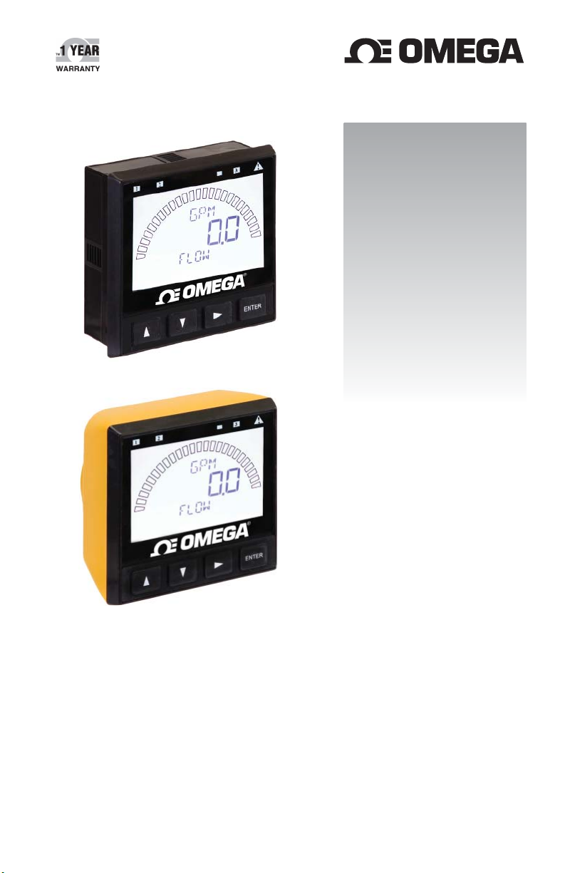
The DPU91 Transmitter, a member of Omega's line of instruments, provides a
single-channel interface for all Flow, pH/ORP, Conductivity/Resistivity, Salinity, and Batch.
The DPU91 is available in either Panel or Field Mount.
Both versions run on 10.8 to 35.2 VDC power (24 VDC nominal),
and can power certain sensors on loop power (see NOTE below).
3. Compatibility
The DPU91 is compatible with all Omega products listed in the column to the right.
pH and ORP electrodes require the Omega PHTX-275 (ISO) or
PHTX-275G (ISO) Sensor Electronics (sold separately).
Conductivity/Resistivity or Salinity measurement requires either the optional
DPU90-C Direct Conductivity/Resistivity Module or the CDTX-285X Series
Conductivity/Resistivity Sensor Electronics (both sold separately).
Flow
FP-5300*, FP-5600*, FP-8500*, FP-5200*, FP-5070, FP-5060, FPB, P-2540*,
FP-3-1500*, FMG-3000, FMG-550
pH/ORP
PHE-2724, PHE-2726 , ORE-2725 with PHTX-275 (ISO) or PHTX-275G (ISO)*
Conductivity/Resistivity, Salinity
CDCE-90 with CDTX-285X or DPU90-C Conductivity/Resistivity Module
CDE-285X with CDTX-285X or DPU90-C Conductivity/Resistivity Module
* Can be run on Loop Power; all other measurement sensors require DC power.
NOTE:
Loop powered systems cannot power both DPU90-COMM and
pH sensors on one system.
If using both DPU90-COMM Module and pH sensors, DC power is required.
3OMEGA DPU91 Transmitter
Page 4
4. Safety Information
Follow instructions carefully to avoid personal injury.
This unit is designed to be connected to equipment which can be hazardous to
persons and property if used incorrectly.
Read and understand all associated equipment manuals and safety warnings before
using with this product.
Remove power to unit before wiring connections.
Wiring connections to this product should only be performed by qualifi ed personnel.
Do not use unit if front panel is cracked or broken.
Warning / Caution / Danger
Indicates a potential hazard. Failure to follow all warnings may lead
to equipment damage, injury, or death.
Electrostatic Discharge (ESD) / Electrocution Danger
Alerts user to risk of potential damage to product by ESD,
and/or risk of potential of injury or death via electrocution.
Personal Protective Equipment (PPE)
Always utilize the most appropriate PPE during installation and
service of Omega products.
NOTE / Technical Notes
Highlights additional information or detailed procedure.
CAUTION
Avoid Electrostatic Discharge (ESD).
Minimize handling of the plug-in modules to reduce the possibility
of damage due to ESD.
Handle modules by the edges.
Never touch any exposed circuitry or contacts.
Wear an anti-static wristband or stand on an anti-static mat, or
keep one hand touching a properly grounded pipe or other piece
of properly grounded metal when handling modules.
OMEGA DPU91 Transmitter4
Page 5

5. Contents
1. Quick Start ............................................................................................. 3
2. Description ............................................................................................. 3
3. Compatibility .......................................................................................... 3
4. Safety Information .................................................................................. 4
5. Contents................................................................................................. 5
6. Dimensions ............................................................................................ 6
7. Module Installation ................................................................................. 7
8. Plug-In Modules ..................................................................................... 7
9. Relay Module ......................................................................................... 8
10. Direct Conductivity/Resistivity Module ................................................... 9
11. Batch Module ....................................................................................... 10
12. DPU90-COMM Module ........................................................................ 10
13. Installation ............................................................................................ 18
14. Wiring ................................................................................................... 20
15. Signal Type: Frequency ....................................................................... 20
16. Signal Type: Digital (S
17. Terminal Identifi cation .......................................................................... 22
18. Sensor Wiring ...................................................................................... 23
19. Sensor Wiring Technical Notes ............................................................ 25
20. Power Wiring........................................................................................ 26
21. Open Collector Wiring .......................................................................... 27
22. Relay Module Wiring ............................................................................ 28
23. Relay Functions ................................................................................... 28
24. Relay and Open Collector Outputs ...................................................... 29
25. Operation ............................................................................................. 34
26. Menu System ....................................................................................... 36
System Setup Menu ..................................................................... 36
VIEW Mode Overview .................................................................. 37
MENU Mode Overview ................................................................. 37
Password Overview ..................................................................... 38
27. Common Menus................................................................................... 39
INPUT Menu ................................................................................. 39
LOOP Menu ................................................................................. 39
RELAY Menu ................................................................................ 40
OPTION Menu ............................................................................. 42
28. Sensor-Specifi c Menus ........................................................................ 43
Flow .............................................................................................. 43
pH ................................................................................................. 45
ORP .............................................................................................. 47
Conductivity/Resistivity ................................................................ 49
Salinity .......................................................................................... 51
29. Troubleshooting ................................................................................... 53
30. Appendix .............................................................................................. 54
31. Averaging ..................................................................................... 54
32. LOG Current Loop Output ............................................................ 55
33. Calibration Procedure: pH ............................................................ 56
34. Calibration Procedure: ORP ......................................................... 58
35. Calibration Procedure: Conductivity/Resistivity ............................ 60
36. Calibration Procedure: Flow ......................................................... 61
37. Calibration Error Messages .......................................................... 62
38. USP Limits .................................................................................... 63
39. Maintenance ........................................................................................ 63
40. Specifi cations ....................................................................................... 64
41. Ordering Information ............................................................................ 70
3
L) ..................................................................... 21
5OMEGA DPU91 Transmitter
Page 6
6. Dimensions
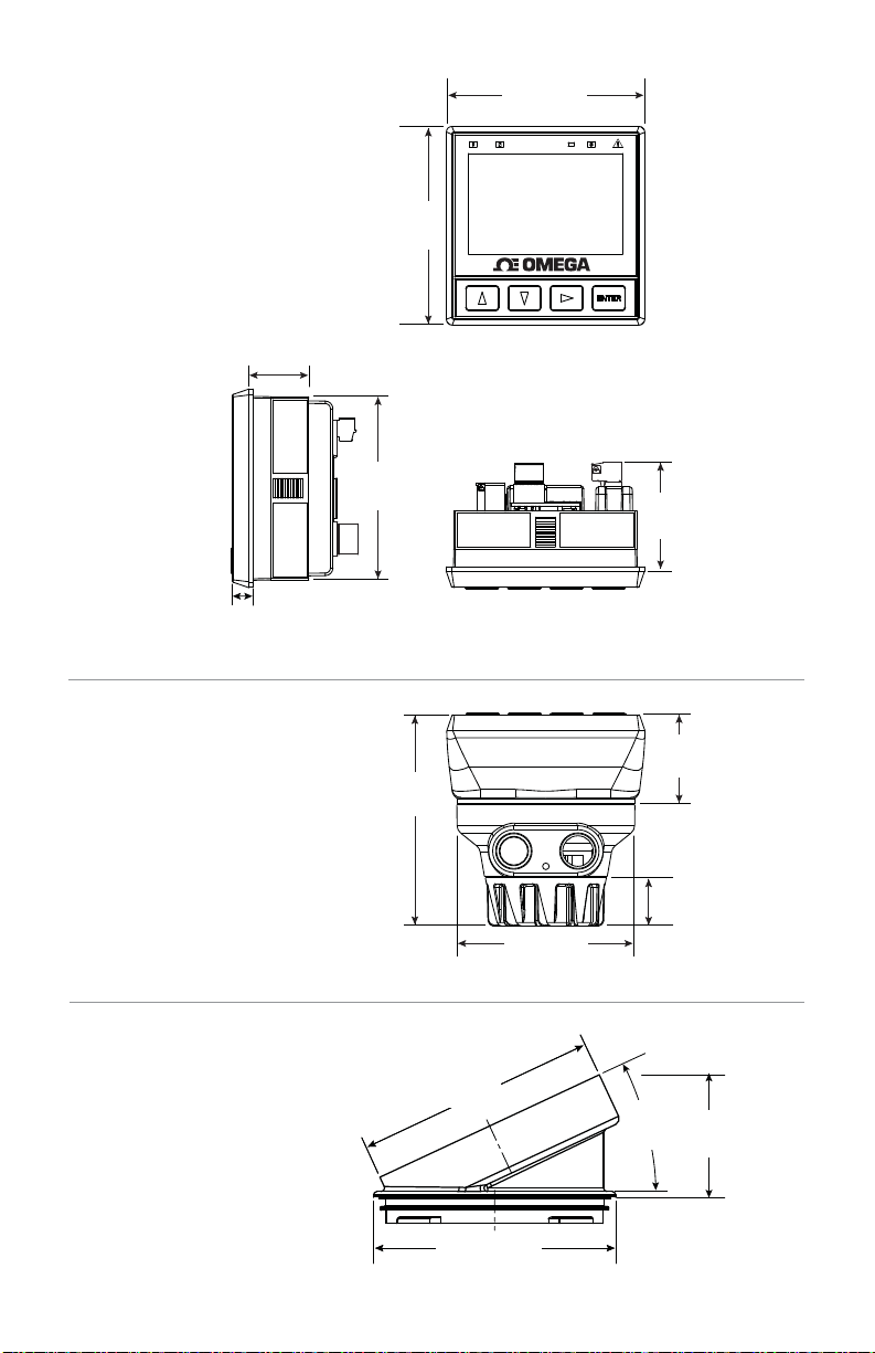
Panel Mount DPU91P
29.97 mm
(1.18 in.)
8.13 mm
(0.32 in.)
99.06 mm
(3.90 in.)
91.44 mm
(3.60 in.)
99.06 mm
(3.90 in.)
Top ViewSide View
®
54.10 mm
(2.13 in.)
Field Mount DPU91
(FP90IM shown)
NOTE: FP90IM
Integral Mounting Kit
sold separately.
DPU90-AK
Angle Adjustment
Adapter Kit
OMEGA DPU91 Transmitter6
107 mm
(4.21 in.)
88.90 mm
(3.50 in.)
88.90 mm
88.90 mm
3.50
(3.50 in.)
(3.50 in.)
44.45 mm
(1.75 in.)
24.13 mm
(0.95 in.)
25°
Ref.
0.68 mm
(0.27 in.)
Page 7
7. Module Installation
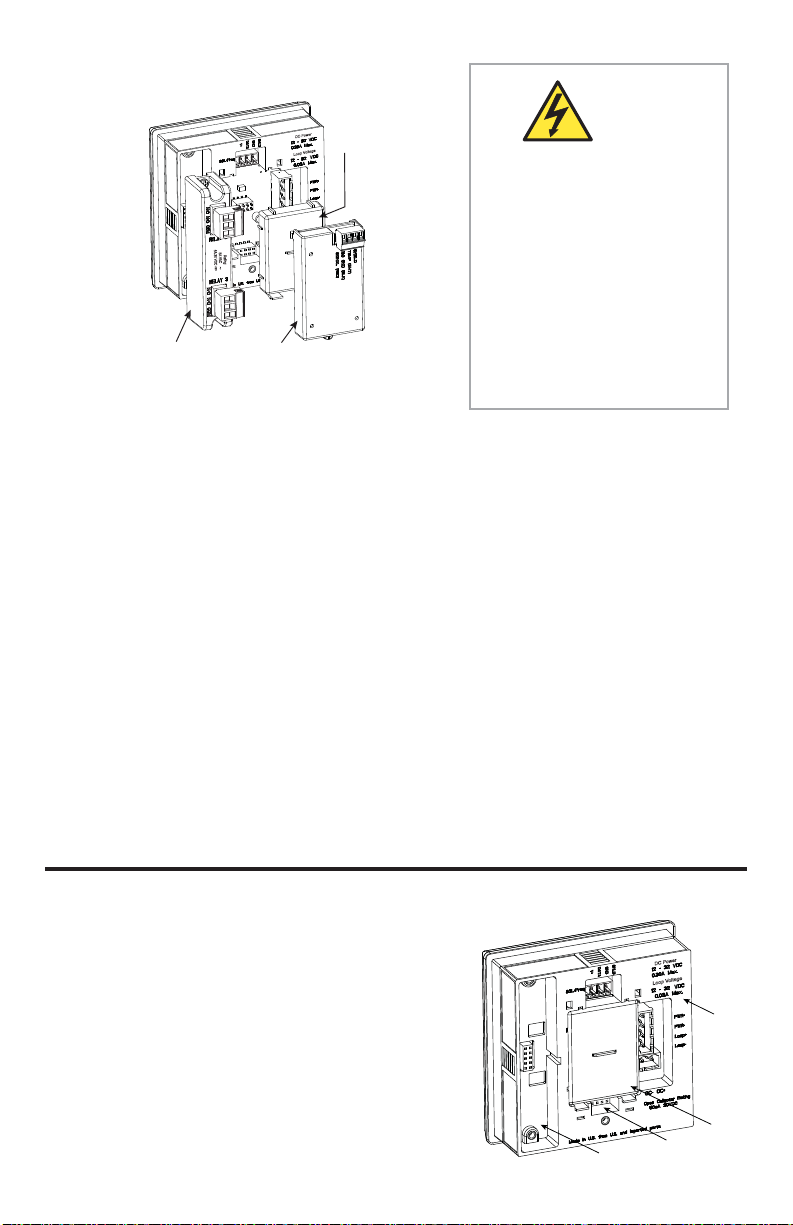
Base Unit
DPU90-COMM
DC Power
Module
Loop Voltage
CAUTION
Exercise care when installing
modules.
Do not bend connecting pins.
5A 30 VDC
5A VAC
Rating:
~
LOOP as well as DC power
MUST be removed BEFORE
installing DPU90-COMM.
Relays may be connected
to external high-voltage
Relay Module
(Panel Mount Only)
Conductivity/Resistivity
Module
power sources or multiple
power sources creating an
electrocution hazard.
If the DPU91 Base Unit will be mounted in a panel, the plug-in modules may be installed
either before or after the base unit is mounted. If the DPU91 Base Unit will be mounted
using the accessory wall mount bracket, install plug-in modules fi rst.
If installing both the Conductivity/Resistivity (Cond/Res) and the DPU90-COMM,
the DPU90-COMM fi rst, then the Cond/Res Module on top of it (see page 9).
install
The Relay, Cond/Res, and Batch Modules attach with screws.
The DPU90-COMM simply plugs in.
To install modules:
Remove power from the DPU91.
Carefully align pins and connectors (do not bend connecting pins) and push module
fi rmly into place, then attach with screw(s) (except DPU90-COMM Module).
To remove modules:
Remove power from the DPU91.
For Relay and Cond/Res Modules, unplug connectors, remove screw(s), and
carefully pull module straight out from the base unit. Do not bend the connecting pins.
For DPU90-COMM, squeeze the tabs on the bottom edge, grasp the module and
pull straight out. Do not bend the connecting pins.
For Batch Module, remove the Relay module. Loosen bottom screw of Batch module.
Carefully grip and squeeze the tabs at the top of the module to release.
Pull module away from the unit. Do not bend the connecting pins
8. Plug-In Modules
Optional modules and accessories are available for the DPU91:
a. Base Unit (required)
b. Slot for optional DPU90-COMM Module
c. Slot for optional Cond/Res Module or
optional Batch Module (DPU91P only)
d. Slot for optional Relay Module
(not available on fi eld mount)
Each item is ordered separately.
Modules are fi eld-replaceable at any time.
See Installation (pg. 18) and
Ordering Information (pg. 70) sections for more details.
DC Power
Loop Voltage
a.
b.
d.
c.
7OMEGA DPU91 Transmitter
Page 8
9. Relay Module
(Panel Mount installations only)
Mfr. Part No. Description
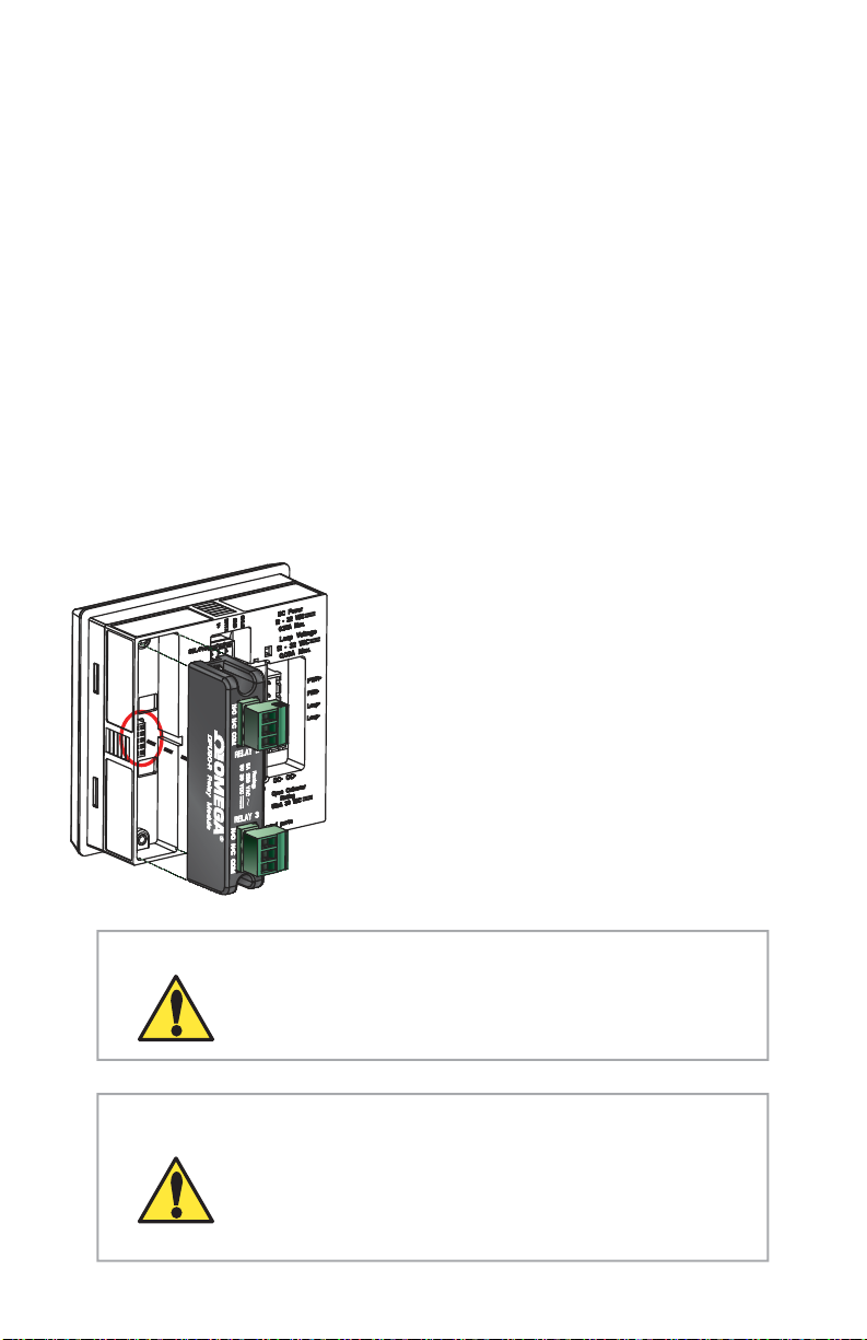
DPU90-R Relay Module - Two dry-contact relays
In addition to the standard programmable Open Collector output in the base unit, the
Panel Mount version of the DPU91 has a slot for an optional Relay Module, which adds
two programmable dry-contact relays. The Open Collector output in the base unit uses the
Relay 1 setting in the menus. If the optional Relay Module is installed, these are assigned
to relays 2 and 3 in the menus.
Dry-contact relays are electromechanical switches with a moving contact armature.
They are suitable for many general-purpose applications, AC or DC, including AC loads up
to 250 V. Install RC Filter Kits, FP90RC, on relays used to switch motor or inductive loads.
Two (2) SPDT dry-contact relay (DCR) inputs
User programmable
250 V, 5 A maximum resistive loading (AC).
Can switch line voltage (typically 120 to 240 VAC)
Can switch DC voltage (< 30 VDC @ 5A)
Larger voltage and current ratings than Open Collector outputs.
For wiring information, refer to the Relay Module Wiring section (page 28).
NOTE:
The Relay Module requires 10.8-35.2 VDC, 300 mA
power connection to DC PWR Terminals.
The Relay Module cannot be used with loop power.
The two red Mechanical Relay Indicator LEDs
on the front panel of the DPU91 show the
status of relays 2 and 3. (Status of all relays
and Open Collector is available at all times
in a single screen in View mode.)
Hysteresis and time delay are adjustable for
each relay.
OMEGA DPU91 Transmitter8
CAUTION
CAUTION
DO NOT bundle Relay Module wiring with other wiring.
Doing so may cause injury and/or damage to
DPU91 Transmitter, Relay Module, and Batch Module.
Switching active loads (usually inductive) can cause
contact arcing suffi cient to damage the relays.
The FP90RC, RC Filter Kit or “snubber” is available as an
accessory to reduce or eliminate these damaging effects.
Recommended for inductive loads greater than 50 VAC
(remote relays, solenoids, pumps, etc.)
Page 9
10. Direct Conductivity/Resistivity Module
Mfr. Part No. Description
DPU90-C Direct Conductivity/Resistivity Module
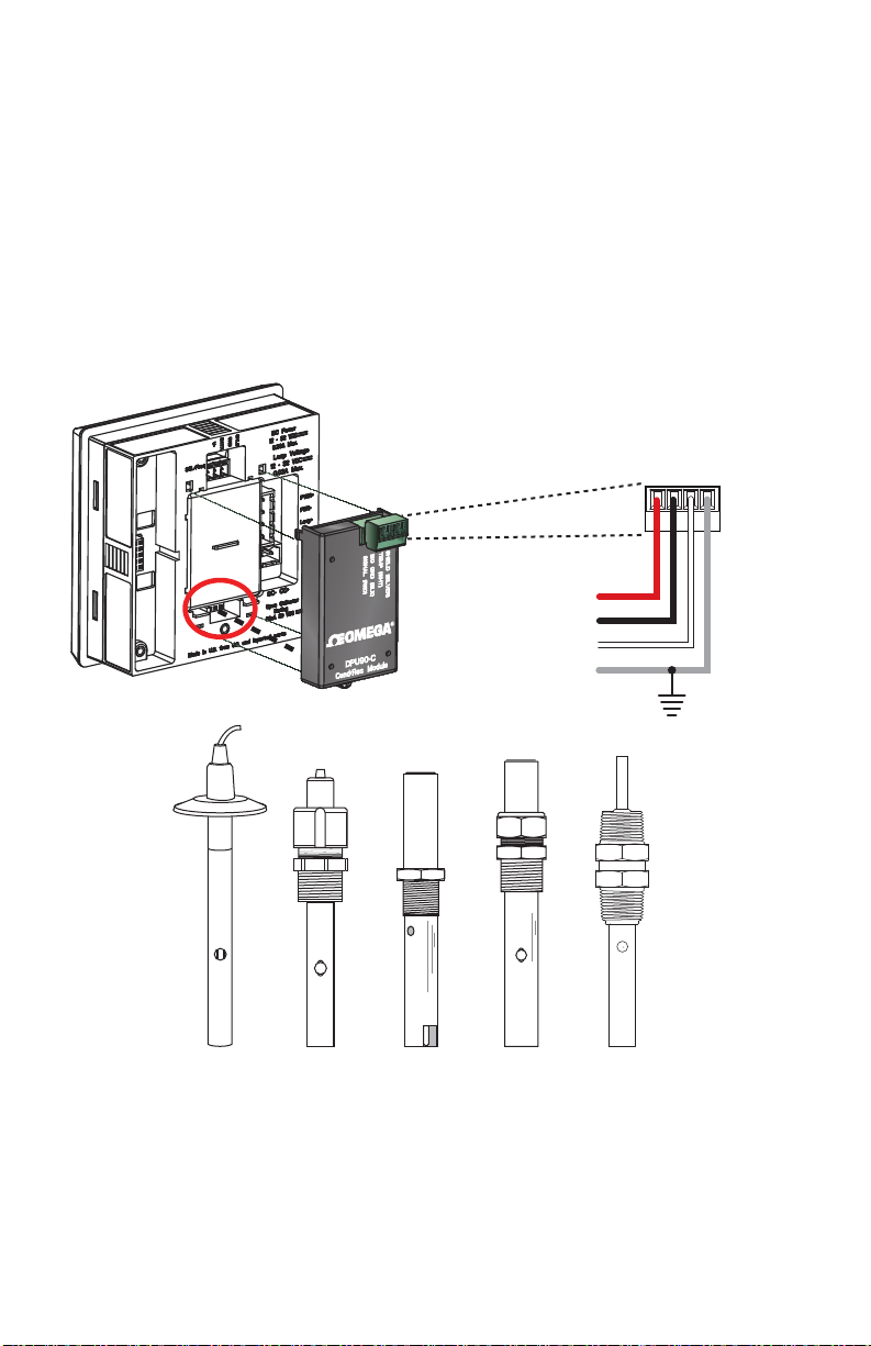
The Direct Conductivity/Resistivity (Cond/Res) Module interfaces Omega CDCE-90 and
CDE-285X Conductivity electrodes directly to the DPU91.
Provides fi ltering and conditioning.
Sensor cable length can be extended to 30 m (100 ft).
CDE-285X sensors come with a cell constant certifi cate to improve the accuracy
of the sensor measurements (see page 50).
Wiring for the CDCE-90 and CDE-285X Conductivity electrodes to the DPU90-C:
SHIELD (SILVER)
ISO GND (BLK)
SIGNAL (RED)
TEMP (WHT)
Red
Black
White
Shield
Sanitary
(S15, S20, T15, T20)
CDCE-90-001/01/1
CDCE-90-10
CDCE-90-20
CDE-285X
9OMEGA DPU91 Transmitter
Page 10
11. Batch Module
Mfr. Part No. Description
DPU90-BCM Batch Module
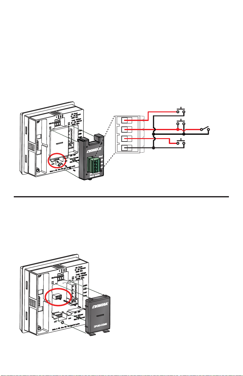
Convert a DPU91P Transmitter (Generation II or later) into a Batch Controller system by
utilizing a Batch Module (DPU90-BCM) and a Relay Module (DPU90-R).
Optional Module Wiring:
• Wire an external button or keypad (customer supplied) to stop, start or resume a
batch remotely.
• Wire an external input that can inhibit a batch from starting.
Full DPU91-BC Batch Controller System manual available at Omega.com
Start
Stop
Inhibit*
Resume
Common
*Wire an external input as override
for preventing batch from starting.
NOTE: The DPU90-BCM is incompatable with the DPU90-C and DPU90-COMM.
12. COMM Module
Mfr. Part No. Description
DPU90-COMM COMM Module
The DPU90-COMM Module enables communication between the DPU91 and a
HART®-enabled device. The HART (Highway Addressable Remote Transducer)
Protocol superimposes digital signals on top of the 4 to 20 mA analog signal.
NOTE:
With DPU90-COMM module installed,
a minimum of 24 V is required for
loop-powered systems.
The black rubber jumper adjacent to the
power terminal should only be removed
when both the DPU90-COMM Module
is utilized and the required sensor cable
length is over 304 m (1000 ft).
HART® is a registered trademark of the HART Communication Foundation, Austin, Texas, USA.
Any use of the term HART hereafter in this document implies the registered trademark.
OMEGA DPU91 Transmitter10
Page 11
How HART® Works
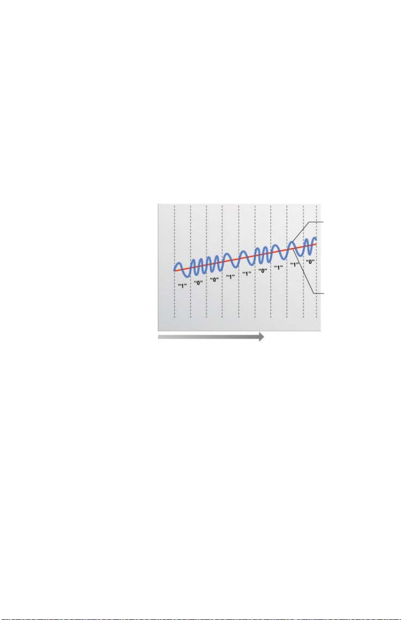
The HART® (Highway Addressable Remote Transducer) Protocol uses Frequency Shift
Keying (FSK) to superimpose digital signals on top of the analog 4 to 20 mA current loop.
This allows two-way digital communication to occur and allows additional information beyond
the normal process data to be communicated to the DPU91.
This digital signal can contain data such as device status, diagnostics, etc.
The HART protocol provides two simultaneous communication channels: a 4 to 20 mA analog
signal and a digital signal. The analog signal communicates the primary measured value using
the 4 to 20 mA current loop. Additional information is communicated using a digital signal
superimposed on the 4 to 20 mA signal.
Communication occurs between two HART-enabled devices, in this application a DPU91 and
a PLC or handheld device, using standard wiring and termination practices.
The HART Protocol communicates at 1200 bits per second without interfering with the
4 to 20 mA signal and allows the PLC or handheld device to communicate two or more
updates per second to and from the DPU91.
Frequency Shift Keying
Digital over Analog
20 mA -
4 mA -
Note: Drawing not to scale
Time
Time
Digital
Signal
Analog
Signal
The HART protocol operates according to the master-slave method. Any communication
activity is initiated by the master, usually a programmable logic controller (PLC) or a data
acquisition system. HART accepts two masters: the primary master - usually the control
system (PLC) - and the secondary master - a PC laptop or handheld terminal used in the fi eld.
HART fi eld devices - the slaves - never send without being requested to do so.
They respond only when they have received a command message from the master.
Once a transaction (i.e., a data exchange between the control station and the fi eld device)
is complete, the master will pause for a fi xed time period before sending another command,
allowing the other master to break in. The two masters observe a fi xed time frame when taking
turns communicating with the slave devices.
As deployed in the DPU91 application, HART allows remote verifying, testing, adjusting and
monitoring of primary and secondary device variables.
Features available in the DPU91 Transmitter with DPU90-COMM Module installed:
• Adjust 4 to 20 mA: Allows fi ne-tuning to compensate for errors in other equipment
connected to the DPU91. Adjust the minimum and maximum current output.
• Supports Multi-Drop Mode: Up to four DPU91 Transmitters can be installed in this mode.
• Supports all Universal HART Protocol Revision 7.2 commands
• Supports many Common Practice Commands
• Makes Primary and Secondary values available at PLC. Secondary values are
sensor-dependent and are available with pH, Conductivity, Resistivity, and Salinity sensors.
11OMEGA DPU91 Transmitter
Page 12
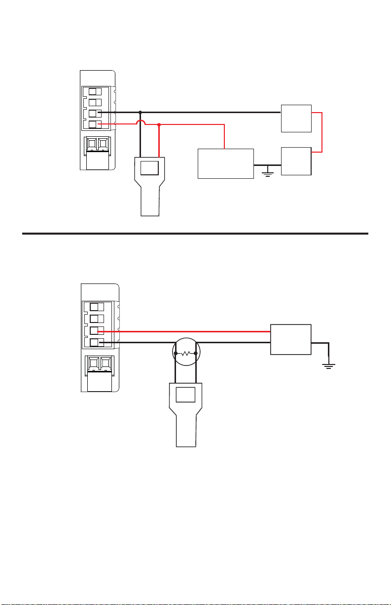
Connecting HART with a Loop-powered sensor
DPU91
Terminal
(Typical installation)
Loop +
Loop –
Black
Red
Optional ammeter
(recommended for
4 to 20 mA trim only)
Hand-held device
(Secondary HART Master)
Connecting HART to a Hand-Held Master Device
DPU91
Terminal
Loop +
Loop –
Red
Black
250
Load Resistor
(Primary HART Master)
–
PLC
Device
+
+
Power
–
Supply
(Typical installation)
+
Power
Supply
–
Hand-held device
(HART Master)
NOTE: From this point forward the term “DPU91 Transmitter” or “Transmitter” will assume
the DPU90-COMM Module is installed unless otherwise noted.
OMEGA DPU91 Transmitter12
Page 13
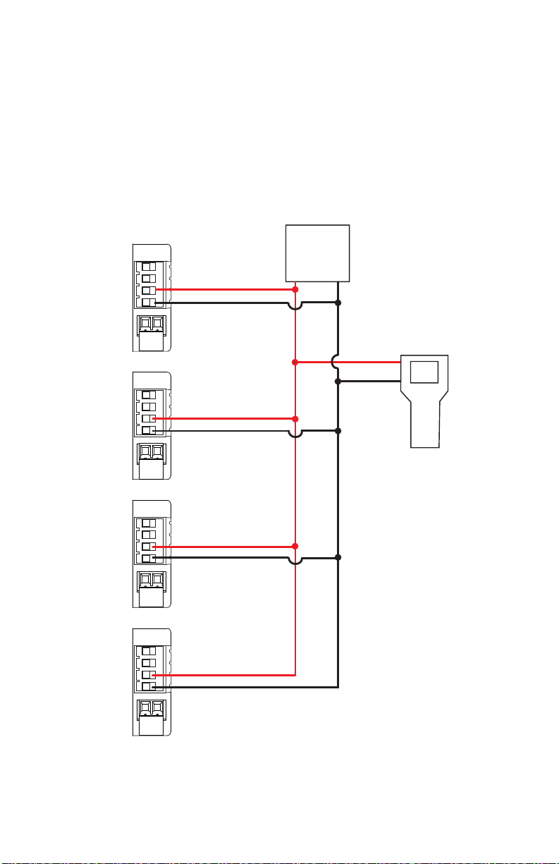
Multi-Drop Mode
Up to four DPU91 Transmitters can be connected in Multi-Drop mode using the
DPU90-COMM Module.
To ensure proper operation in Multi-Drop mode, confi gure each DPU91 Transmitter with
its own poll address using a confi guration tool (laptop or hand-held device).
After confi guring the DPU91 Transmitter for multi-drop function, reset the Transmitter
(remove power for fi ve seconds then apply power) before use.
Connecting HART in Multi-Drop mode
Device 1
Loop +
Loop –
Device 2
Loop +
Loop –
Device 3
Loop +
Loop –
9900
DPU91
Connections
Terminal
Red
Black
Red
Black
Red
Black
(HART Master)
PLC
Device
+
(Typical four-unit installation)
–
Red
Black
Hand-held device
(Secondary HART Master)
Device 4
Loop +
Loop –
Red
Black
13OMEGA DPU91 Transmitter
Page 14

Operation
Loop Powered systems require a minimum of 24 VDC.
If connecting with DC, nominal 12 VDC is acceptable (see Power Wiring page 26).
In pH, Conductivity, Resistivity and Salinity systems the secondary variable represents
temperature.
Loop Current Trim Procedure
The Loop Current HART commands allow a Master HART device to update a loop current
value in the DPU91 and to perform a two-point calibration (zero and span) of the loop current.
1.
Use Command 40 (Enter/Exit Fixed Current Mode) to update the 4.00 mA current.
2.
Using the measured value of your reference instrument (either a digital multimeter or the
HART Master device), set the zero trim using Command 45 (Trim Loop Current Zero).
The transmitter will then trim its calibration and return the loop current value in the
response message. The response value may differ slightly from the value sent by the
Master due to rounding.
Use Command 40 (Enter/Exit Fixed Current Mode) to update the 20.00 mA current.
3.
Using the measured value of your reference instrument (either a digital multimeter or the
4.
HART master device), set the span trim using Command 46 (Trim Loop Current Gain).
The transmitter will then trim its calibration and return the loop current value in the
response message. The response value may differ slightly from the value sent by the
Master due to rounding.
5. Repeat steps 1 through 4 as needed to gain the accuracy desired.
Once the loop current is calibrated to your satisfaction, return the device to normal
operation by issuing Command 40 (Enter/Exit Fixed Current Mode) with a value of 0.0.
This will take the DPU91 out of fi xed current mode.
Note:
The following are not accessible via the DPU91 keypad with the DPU90-COMM installed:
• Trim Loop Current
• Test Loop Current
These functions are only accessible via the HART interface.
Changes to Units of Measure in Transmitter
HART devices can be used to change the units of measure in a DPU91 Transmitter.
After an update, you must cycle power to the DPU91 (remove power for 5 seconds,
then restore power). In a fl ow system, the units update automatically and it is not
necessary to cycle power to the transmitter.
OMEGA DPU91 Transmitter14
Page 15

HART Commands
Universal Commands
All HART Rev. 7.2 Universal Commands are supported:
CMD
ID
0 Read Unique Identifi er 14
1 Read Primary Variable 15 Read Device Information
2 Read Loop Current And Percent Of Range 16 Read Final Assembly Number
3 Read Dynamic Variables And Loop Current 17 Write Message
6 Write Polling Address 18 Write Tag, Descriptor, Date
7 Read Loop Confi guration 19 Write Final Assembly Number
8 Read Dynamic Variable Classifi cation 20 Read Long Tag
9 Read Device Variable With Status 21
11 Read Unique Identifi er Associated With Tag 22 Write Long Tag
12 Read Message 38 Reset Confi guration Changed Flag
13 Read Tag, Descriptor, Date 48 Read Additional Device Status
Function
CMD
ID
Read Primary Variable Transducer
Information
Read Unique Identifi er Associated With
Long Tag
Function
Command 0 – Read Unique Identifi er
Returns device type, device and software revision levels, device status, and codes for
the manufacturer and product information.
Command 1 – Read Primary Variable
Returns the numeric value of the Primary Variable (the 4 to 20 mA current loop) and the
unit code for that value (e.g. ’45.3’ and ‘Degrees Celsius’).
Command 2 – Read Loop Current and Percent of Range
Returns the loop current value of the 4 to 20 mA current loop and the percent of range
(e.g. ’12.0’ and ‘50%’).
Command 3 – Read Dynamic Variables and Loop Current
Returns the loop current value of the 4 to 20 mA current loop, as well as the numeric
value of the Secondary Variable (if present) and the Secondary Value’s unit code.
Command 6 – Write Polling Address
Enables (or disables) Multi-Drop mode. While in Multi-Drop mode, loop current is held at
a fi xed value and is no longer available for signaling. Also sets the polling address of the
device for Multi-Drop mode.
Command 7 – Read Loop Confi guration
Reads the polling address of the device and the loop confi guration (see Command 6).
Command 8 – Read Dynamic Variable Classifi cations
Returns the classifi cation code for the Primary Variable and Secondary Variable
(if present).
Command 9 – Read Device Variable with Status
Returns the value, status, variable code, variable classifi cation and unit code of up to
four device variables.
15OMEGA DPU91 Transmitter
Page 16

Universal Commands - Continued
Command 11 – Read Unique Identifi er Associated with Tag
Returns all identity information associated with the device, i.e., the device type,
device revision level and Device ID. Issued using the ‘tag’.
Command 12 – Read Message
Read back the message stored in the device (see Command 17).
Command 13 – Read Tag, Descriptor, Date
Reads the tag, descriptor and date values contained within the device (see Command 18).
Command 14 – Read Primary Variable Transducer Information
Reads transmitter serial number, unit code, upper and lower limits and minimum span
for primary variable.
Command 15 – Read Device Information
Returns the alarm selection code, transfer function code, upper and lower range values,
write protect code and unit code.
Command 16 – Read Final Assembly Number
Returns the assembly number of the device. This will be defi ned by the customer
(see Command 19).
Command 17 – Write Message
Write a message to be stored in the device (see Command 12).
Command 18 – Write Tag, Descriptor, Date
Writes the tag, descriptor and date values into the device (see Command 13).
Command 19 – Write Final Assembly Number
Writes the fi nal assembly number of the device (see Command 16).
Command 20 – Read Long Tag
Read the 32-byte long tag. The ‘long tag’ is separate from the ‘tag’ that is used in
Commands 13 & 18.
Command 21 – Read Unique Identifi er Associated with Long Tag
Returns all identity information associated with the device - the device type,
device revision level and Device ID. Issued using the long tag.
Command 22 – Write Long Tag
Write the 32-byte long tag (see Command 20).
Command 38 – Reset Confi guration Changed Flag
Resetting the device’s confi guration changes counter back to 0.
Command 48 – Read Additional Device Status
Returns extended device status information.
OMEGA DPU91 Transmitter16
Page 17

Supported HART Common Practice Commands
The following Common Practice Commands are supported.
CMD
ID
40 Enter/Exit Fixed Current Mode
45 Trim Loop Current Zero
46 Trim Loop Current Gain
54 Read Device Variable Information
Function
Command 40 - Enter/Exit Fixed Current Mode
The loop current of the DPU91 is set to the value transmitted in the command
(in milliamperes). Setting a level of ‘0’ exits Fixed Current Mode.
If the device is in Multi-Drop mode, Error Code 11 will be returned.
Command 45 – Trim Loop Current Zero
The DPU91 will trim its offset of the loop current to match the loop current value sent to it.
This is typically performed at 4.00 milliamperes to optimize calibration.
Command 46 – Trim Loop Current Gain
The DPU91 will trim the gain of the loop current to match the loop current value sent to it.
This is typically performed at 20.00 milliamperes to optimize calibration.
Command 54 – Read Device Variable Information
Returns serial number, limits, damping value and minimum span for a selected device
variable.
Unit Codes
HART Commands
The DPU90-COMM module uses standard HART Foundation Protocol 7.2 unit codes.
The unit code allows the HART Master to interpret and display the units of measure
(e.g., GPM, PPB, °F, etc.) with two exceptions.
The following Unit Codes will not be interpreted by the HART Master:
Code Measurement Unit
240 Cubic Centimeters
244 Parts per Thousand
A HART Master will display these unit codes instead
of the units of measure that the code represents.
17OMEGA DPU91 Transmitter
Page 18
13. Installation
System Start-up: Step 1
Prepare the transmitter installation location.
If the back of the transmitter is diffi cult to access when installed,
wire the removable terminal blocks fi rst, then install it completely.
Next step: Wiring (see pg. 20)
For future reference, for each installation, it is recommended to record the
part number and serial number of each of the components listed here:
Facility Tag Number or System ID (user assigned):_____________________
Base unit DPU91 / DPU91P S/N __________________
Relay Module DPU90-R S/N __________________
Cond/Res Module DPU90-C S/N __________________
COMM Module DPU90-COMM S/N __________________
Batch Module DPU90-BCM S/N __________________
Do not mount in direct sunlight.
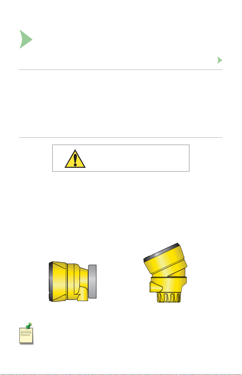
Field Mount Installation
Field mounting requires a separate mounting kit (see Ordering Information, page 70):
• PHTX-27 and FP90UM Universal Mount Kit
• FP90IM or FP90IM34 Integral Mount Kits
• DPU90-AK Angle Adjustment Adapter Kit (accessory for either of the above)
Field installation instructions are included with each of the mounting kits.
For suffi cient wiring clearance, the DPU90-AK (Angle Adjustment Adapter) is required for
Field Mount installations using the DPU90-C (Direct Conductivity/Resistivity Module).
Field Mount with
PHTX-27 and FP90UM
Universal Mount Kit
For Field Mount installations, refer to the wiring diagram inside the Field Mount housing.
OMEGA DPU91 Transmitter18
Field Mount with
FP90IM or FP90IM34
Integral Mount Kit and
Angle Adjustment Adapter
Page 19
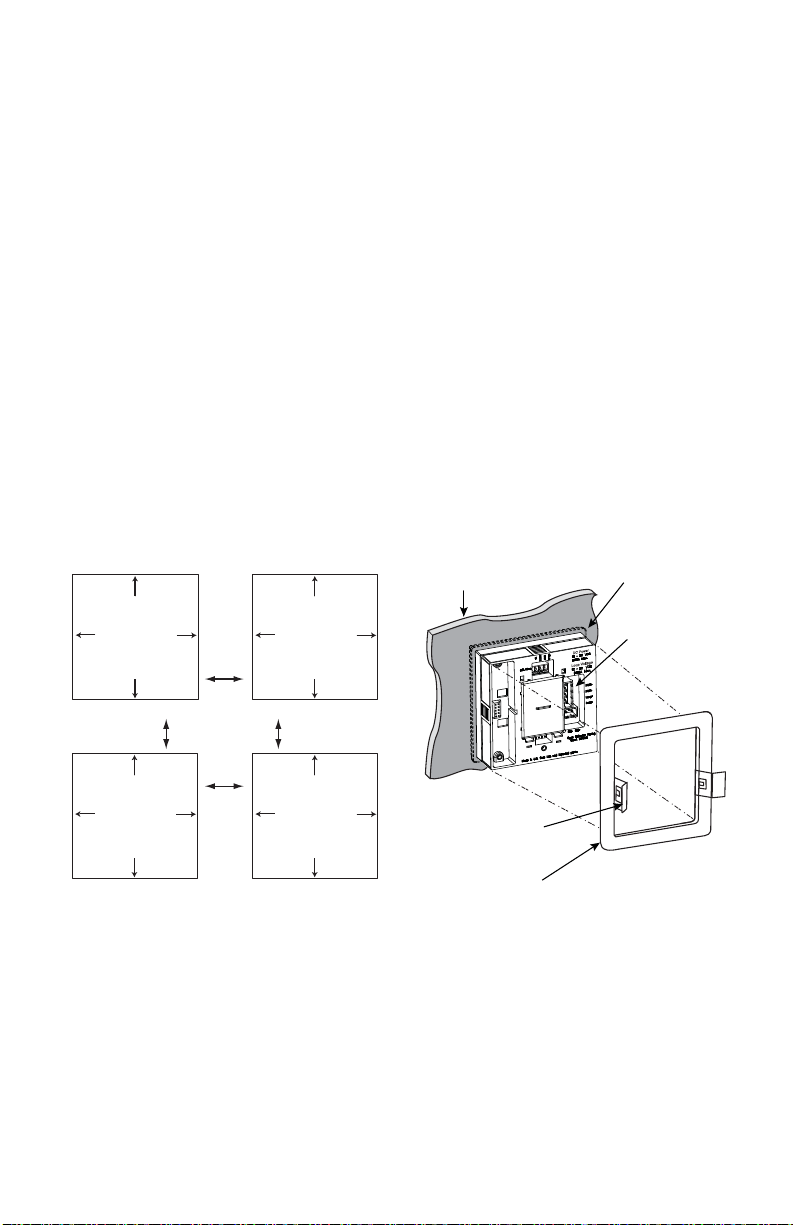
Panel Mount Installation
Tools and Equipment Required
Fine-tooth fi le
¼ DIN punch or jigsaw suitable for cutting panel opening to within 1 mm (0.04 in)
tolerance.
¼ DIN punches are available and recommended for creating clean, precise
openings quickly and easily in most instrument panels.
If a punch is not available, a jigsaw or other cutting tool can be used.
An adhesive template is provided to help guide the cutting process.
De-burr and smooth the opening with a fi le.
1. The panel mount transmitter is designed for installation using a ¼ DIN punch.
Recommended clearance on all sides between instruments is 25 mm (1 in).
2. Place gasket on instrument, and install in panel.
3. Slide mounting bracket over back of instrument until bracket snaps into latches on
sides of instrument.
To remove:
1. Secure instrument temporarily with tape from front or grip from rear of instrument.
DO NOT RELEASE.
2. Press bracket clips outward and remove.
gasket on front
side of panel
terminal
blocks
DC Power
Loop Voltage
Panel Cutout
92 x 92 mm
(+ 0.8, - 0 mm)
3.6 x 3.6 in.
(+0.031, -0 in.)
Panel Cutout
92 x 92 mm
(+ 0.8, - 0 mm)
3.6 x 3.6 in.
(+0.031, -0 in.)
panel
Panel Cutout
92 x 92 mm
(+ 0.8, - 0 mm)
3.6 x 3.6 in.
(+0.031, -0 in.)
minimum
clearance
25 mm
(1 in.)
Panel Cutout
92 x 92 mm
(+ 0.8, - 0 mm)
3.6 x 3.6 in.
(+0.031, -0 in.)
Quick-clip
mounting
bracket
19OMEGA DPU91 Transmitter
Page 20
14. Wiring
System Start-up: Step 2
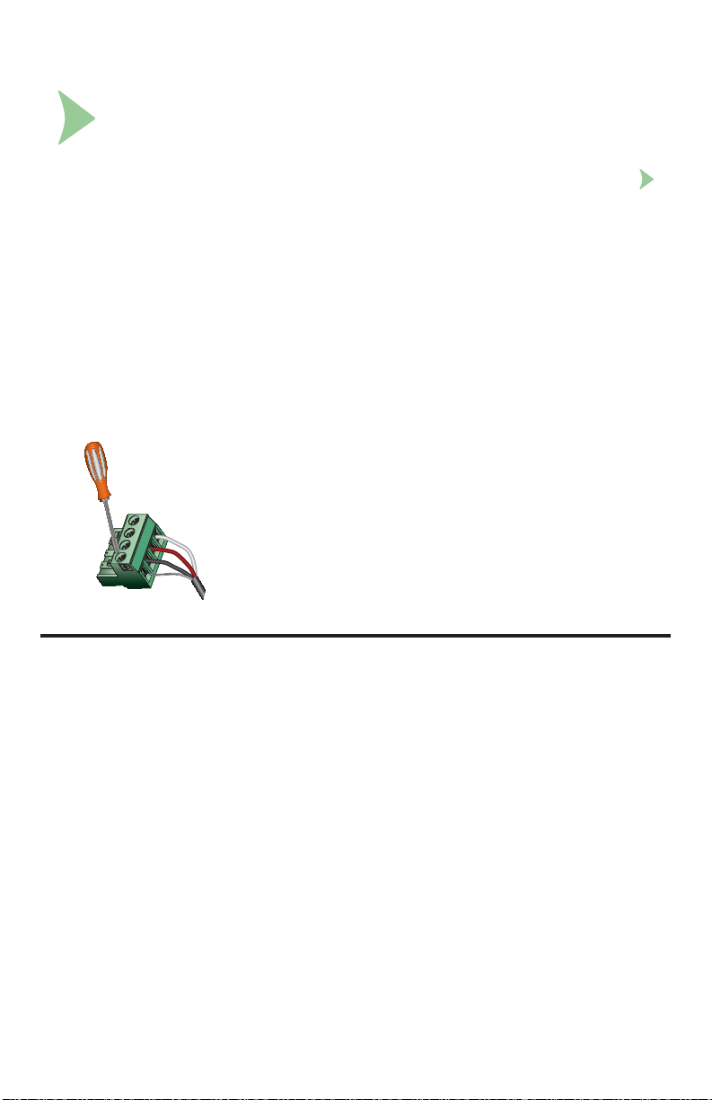
Wire the transmitter for all connections with the power off. Keep any 4 to 20 mA
and relay-actuated output devices that are connected to it offl ine at this time.
Wiring the sensors (pg. 23), power (pg. 26) and relay(s) (pg. 28).
Next step: Relay Functions (see page 28).
Wiring Tips:
Do not route the sensor, DC power, or 4 to 20 mA cables in conduit containing
AC power wiring. Electrical noise may interfere with sensor signal.
Routing the sensor cable in grounded metal conduit can help prevent electrical
noise and mechanical damage.
Seal the cable entry points to prevent moisture damage.
Only one wire should be inserted into a terminal.
Splice double wires outside the terminal or use appropriate wire ferrule,
not to exceed 2 mm (0.08 in) diameter.
All wiring connections to the DPU91 are made via removable terminals.
In general:
The Power, Loop, Relay, and Open Collector plugs
accept 12 to 28 AWG wire.
3
The S
To reduce fraying: strip 7 mm (0.28 in.) of insulation
Insert wire tip or ferrule completely into the terminal and
Do not allow any AC leads that may be connected to the
L/Freq plug and the Cond/Res Module plug
accept 16 to 28 AWG wire.
from wire tips and tin bare ends.
secure with the screw.
internal relays to come in contact with low voltage wiring.
15. Signal Type: Frequency
Omega fl ow sensors FP-5300, FP-8500, FP-5600, FP-5200, FPB, FP-2540, FP-3-1500,
FP-5060, FP-5070 provide a frequency output
Omega fl ow sensors FMG-3000 and FMG-550 can be confi gured with either Digital (S
or Frequency outputs, see pages 20 and 21).
The maximum allowable cable length for sensors with frequency output is dependent
upon the output signal strength of the sensors themselves, and the degree to which the
signals are susceptible to EMI or "noise." This is largely a function of whether the sensors
are self-powered (FP-5300, FP-8500, and FP-5200), or powered by an external source.
The input terminals on the DPU91 carry frequency data signals from the sensor.
Do not route sensor or output cables in conduit containing
AC power wiring.
Electrical noise may interfere with sensor signal.
Routing cable in grounded metal conduit will help prevent electrical noise and
mechanical damage.
Seal cable entry points to prevent moisture damage.
Only one wire should be inserted into a terminal.
Splice double wires outside the terminal.
In case of noise interference, ground the sensor SHIELD wire to a local earth
ground at a point near the sensor
.
Consult the sensor manual for additional wiring information.
OMEGA DPU91 Transmitter20
3
L)
Page 21
16. Signal Type: Digital (S3L)
The input terminals on the DPU91 carry Digital (S3L) serial data from the sensor.
Do not route sensor or output cables in conduit containing AC power wiring.
Electrical noise may interfere with sensor signal.
Routing cable in grounded metal conduit will help prevent electrical noise and
mechanical damage.
Seal cable entry points to prevent moisture damage.
Only one wire should be inserted into a terminal.
Splice double wires outside the terminal.
TOTAL cable length from I/O devices to transmitter must not exceed 305 m (1000 ft).
In case of noise interference, ground the sensor SHIELD wire to a local earth ground
at a point near the sensor.
Consult the sensor manual for additional wiring information.
The maximum cable length of the Digital (S
of sensors connected and the size of the conductors in the cable. For best results,
determine the maximum cable length for the system before routing cables.
There are several methods that can help route the digital cables and remain within
the distance limitations.
Maximum total cable length of the Digital (S
Frequency Output
Flow sensors
FP-5300 / 5800 X
FP-5200 X
FP-5060 / 5070 X
FP-5600 / 5800A X
FP-2540 X
FMG-3000 / 550 X
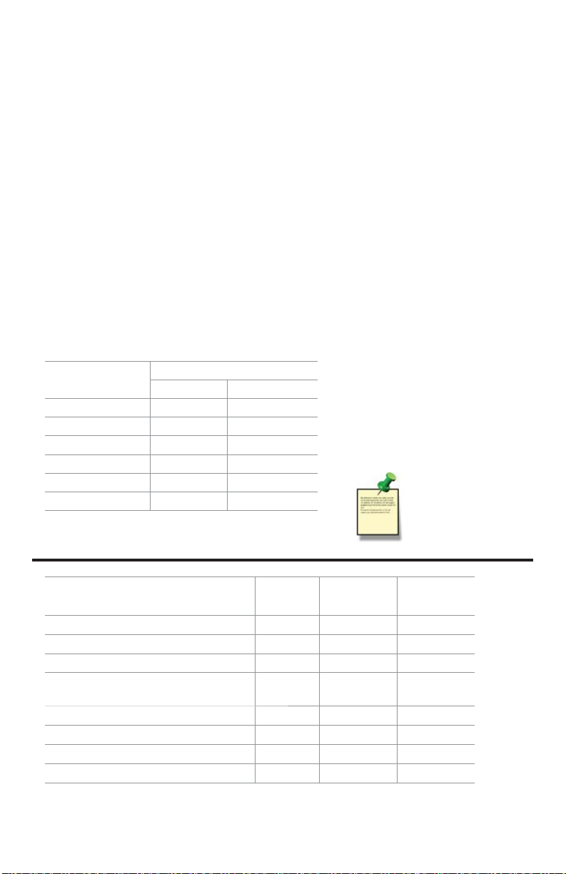
Maximum Cable Length
60 m (200 ft) 305 m (1000 ft)
3
L) bus varies depending on the types
3
L) Bus:
The quality of the cable used in
the bus determines the maximum
length of all branches combined.
The maximum cable length may
not exceed 305 m (1000 ft),
regardless of current requirements.
In case of noise
interference,
connect the
cable shield
to earth ground.
3
L)
Sensor model
Freq
Output
Digital (S
Output
Run on
Loop Power
FP-2540 / 5200 / 5300 / 5600 / 8500 XX
FP-5060 / 5070 X
FMG-3000 / 550 XX
PHE-2724 / 2726
ORE-2725
X
PHEH-275X XX*
CDCE-90-X X
CDE-285X X
CDTX-285X X
*A minimum of 24 VDC Loop Power is required for the PHEH-275X.
21OMEGA DPU91 Transmitter
Page 22
17. Terminal Identifi cation
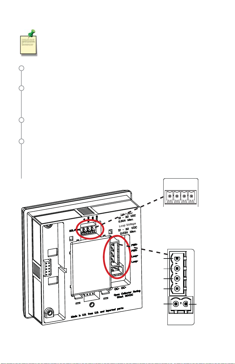
The DPU91 requires regulated 10.8 to 35.2 VDC (24 VDC nominal)
from an external power supply (not supplied).
Maximum current draw is:
200 mA = DPU91 without Relay module
300 mA = DPU91 with Relay module
Terminals 1-2: DC Power
Required by the instrument
10.8 to 35.2 VDC input power to sensors, relays and the LCD backlight
Terminals 3-4: Loop Power (may also be used for system power)
10.8 to 35.2 VDC
NOTE: Backlight, LEDs, and optional Relay Module do not operate on loop
power. Any connected sensors or sensor electronics that cannot operate on
loop power will also be inoperative.
Terminals 5-6: Open Collector
Software selectable for Normally Open or Normally Closed.
May be disabled (Off) if not used.
3
Terminals 7-10: Digital (S
7: V+: +5 VDC out to sensor (black wire)
8: DATA: Input signal from sensor (red wire)
9: GND: Sensor ground (white wire)
10: SHLD: Cable shield
L)/Frequency Input
Digital (S3L)/Freq
V+
DATA
SHLD
GND
DC Power
Loop Voltage
OMEGA DPU91 Transmitter22
Connect sensor wires
here as shown in the
following fi gures.
Power
1
2
3
4
5
PWR+
PWR–
Loop+
Loop–
6
OC- OC+
Connect power and
open collector wires here as
shown on pages 26 and 27.
10978
Page 23
18. Sensor Wiring
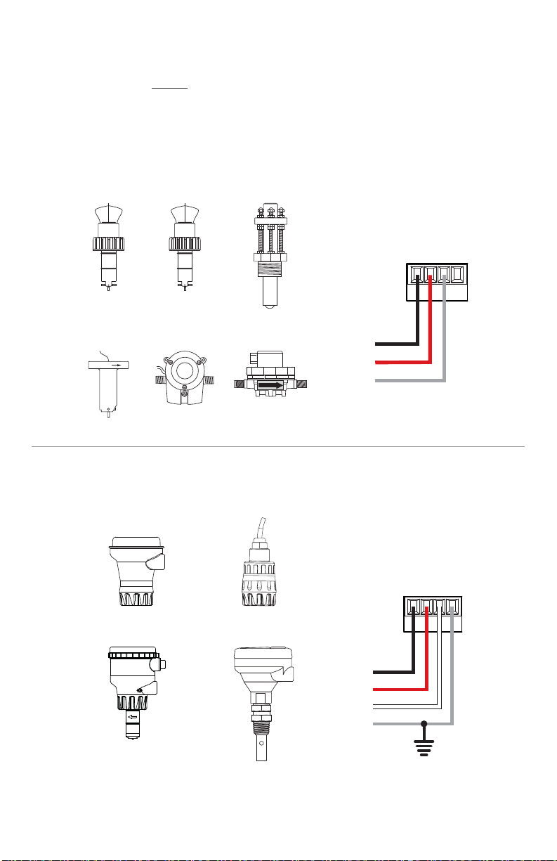
NOTE: Loop Power cannot be used to power Omega models
FP-5060, FP-5070, FMG-3000 or FMG-550 Flow sensors.
Wiring for:
FP-5300
FP-5800
FP-5200
Wiring for:
FP-5600
FP-5800A
FP-2541
FP-3-1500-3B
FP-5060 FP-5070
FLOW
PHEH-275 PHEH-275Y
Frequency
SHLD
DATA
GND
V+
No connection
Black
Red
FLOW
Shield
DPU91 Inputs
SHLD
DATA
GND
V+
FMG-3000-PP-D*
*Display Magmeter
CDTX-2850
Black
Red
White
Shield
NOTE: The CDTX-2850 has no SHIELD wire.
23OMEGA DPU91 Transmitter
Page 24
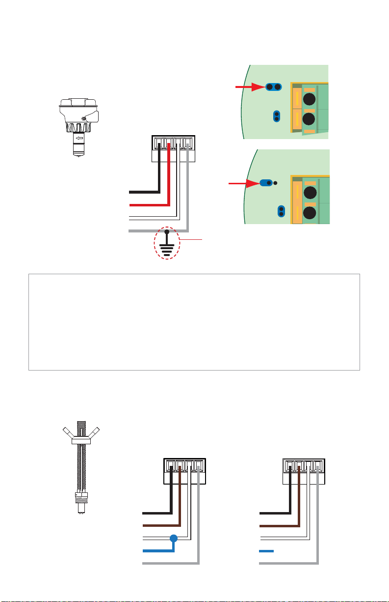
18. Sensor Wiring - continued
Wiring for:
FMG-3000-PP
Blind Magmeter
Frequency
4
SHLD
DATA
GND
Black
Red
White
Shield
V+
3
S L
3
4
3
Only in case of EMI interference
See Frequency Output Technical Notes
(FMG-3000 & FMG-550)
Input Wiring for FMG-3000 and FMG-550 sensors
3
• Either Frequency or Digital (S
• Omega recommends using Digital (S
L) may be used.
3
L) output for increased accuracy and
the ability to display reverse fl ow (negative numbers).
• Input type is selected by choosing between “SENSOR FREQ” and "SENSOR S3L"
in the FLOW sensor type INPUT menu (see page 43).
• Loop Power cannot be used to power these sensors.
Wiring for:
FMG-550
OMEGA DPU91 Transmitter24
Black
Brown
White
Blue
Shield
V+
SHLD
DATA
GND
Black
Brown
White
Blue
Shield
FrequencyDPU91 Inputs
No
X
connection
V+
SHLD
DATA
GND
Page 25

19. Sensor Wiring Technical Notes
Flow Sensors Technical Notes:
• See corresponding product manuals for maximum cable length.
• Maintain cable shield through cable splice.
• Route sensor cable away from AC power lines.
• FP-5200, FP-5300, and FP-5800 installations, connect the silver (shield) wire to earth
ground in case of EMI noise interference.
PHEH-275, FMG-3000-PP-D, CDTX-2850 Technical Notes:
• Use three conductor shielded cable for sensor cable splices up to 305 m (1000 ft) max.
• Maintain cable shield through cable splice.
• Route sensor cable away from AC power lines.
• Connect the silver (shield) wire to earth ground in case of EMI noise interference.
CDTX-2850
Technical Notes:
• The CDTX-2850 has no SHIELD wire.
• To work correctly with the DPU91, the CDTX-2850 must be set for the custom cell
constant or the actual probe cell constant and the DPU91 set for a 1.0 cell constant.
FMG-3000 Technical Notes:
• When the blue jumper illustrated here is placed over both pins, the FMG-3000-PP
(Blind Magmeter) outputs an open collector frequency signal.
• When the jumper is removed (or placed over one pin for storage) the FMG-3000-PP
outputs a digital (S
3
L) signal (recommended).
FMG-3000 and FMG-550 Frequency Output Technical Notes:
• The frequency output will be displayed as positive fl ow regardless of the fl ow direction.
• 5 VDC power required by the FMG sensors is supplied by the DPU91.
No additional power is required.
• Connect the silver wire (shield) to earth ground in case of EMI noise interference.
If EMI noise interference continues,
•
disconnect silver wire (shield) from DPU91.
FMG-550 Technical Notes:
• The FMG-550 open collector frequency signal output can be connected to the DPU91.
25OMEGA DPU91 Transmitter
Page 26
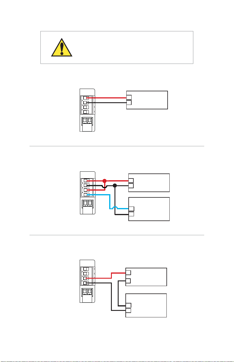
20. Power Wiring
Stand-alone application, no current loop used
CAUTION!
DO NOT connect your DPU91 to AC power.
The DPU91 MUST be powered by
10.8 to 35.2 VDC ONLY.
PWR+
PWR–
Loop+
Loop–
Red
Black
+
Power Supply
–
10.8 to 35.2 VDC
Connection to a PLC/Recorder, separate supply
PWR+
PWR–
Loop+
Loop–
Red
Black
Blue
Power Supply
+
10.8 to 35.2 VDC
–
PLC or Recorder
Loop Input
+
4 to 20 mA
–
Loop Powered
PWR+
PWR–
Loop+
Loop–
Black
Red
+
Power Supply
–
10.8 to 35.2 VDC
PLC or Recorder
–
Loop Input
4 to 20 mA
+
NOTE:
Loop Power cannot be used to
power certain Omega sensors.
See table on page 21.
OMEGA DPU91 Transmitter26
Page 27
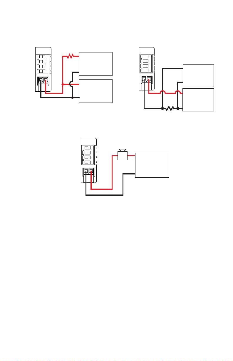
21. Open Collector Wiring
NPN Style Wiring
Pull-Up Resistor
..ȍ:
PWR +
PWR –
Loop +
Loop –
OC –
OC+
9WR9
Power
Supply
Gnd
Input
PLC
Gnd
3:5
3:5±
Loop +
/RRS±
2&±
If PLC needs 0 logic input when relay is not energized,
set NORMAL to CLOSED in the RELAY menu when
using the Open Collector (R1) with NPN style wiring.
PWR +
PWR –
Loop +
Loop –
OC – OC+
Alarm
PNP Style Wiring
OC+
Pull-Down Resistor
..ȍ:
V+
Power
Supply
Gnd
Input
Gnd
9WR9
Power
Supply
Gnd
with NORMAL
set to OPEN.
PLC
• DPU91 Open Collector (R1) output provides high-speed switching capability.
• Signal frequencies can reach 400 pulses per minute.
• DPU91 Open Collector (R1) output connection is dependent upon the type of
circuit being controlled by the output.
• Most indicating instruments or control system inputs require a signal voltage
of 0 to 5 V (TTL or CMOS logic levels) or 0 to 24 V.
• DPU91 Open Collector output circuits must be equipped with a pull-up or
pull-down resistor (not supplied)
• Quality regulated 5 to 24 V (depending on the application) power supply
(not supplied) is recommended to function properly.
27OMEGA DPU91 Transmitter
Page 28
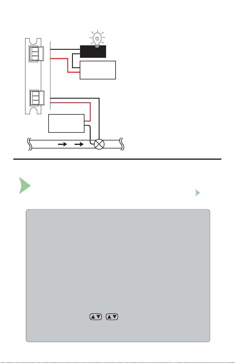
22. Relay Module Wiring
NO = normally open
(closes when energized)
NO
NC
RELAY 2RELAY 3
C
ALARM!
AC or DC
power
NC = normally closed
(opens when energized)
The alarm is OFF during normal
operation, and will go ON when
relay energizes according to
NO
NC
C
AC or DC
power
DPU91 Relay settings.
The valve is ON during normal
operation, and will go OFF when
Valve
Flow
relay energizes according to
DPU91 Relay settings.
23. Relay Functions
System Start-up: Step 3
Set your relay functions to your own application requirements.
Next step: System Setup (see page 36).
Once a setting is saved it becomes immediately active.
1. Go to the Relay Menu (RELAY fl ashing on screen, press ENTER).
2. If prompted, select desired source.
3. Press to relay MODE selection screen.
4. If necessary, press and then or to select R1 MODE LOW.
Press ENTER to confirm.
5. Press to R1 SET LOW. Press to enter GPM value of 5.5.
6. Press ENTER to save.
7. Scroll to the R1 HYSTERESIS menu.
8. Press to edit.
9. Set the hysteresis for this relay. This affects the turn off only: 2.5 gpm.
10. Press ENTER.
11. Scroll down to the R1 ON DELAY menu.
12. Press to edit.
13. Set the turn-on delay in seconds for the relay: 15.0.
14. Press ENTER.
15. Exit to View Mode.
Relay function can be tested in the RELAY menu.
SET LOW + hysteresis = OFF point: 5.5 + 2.5 = 8.0
OMEGA DPU91 Transmitter28
Page 29

24. Relay and Open Collector Outputs
RELAY HIGH and LOW Settings
Depending on the desired function of the circuit attached to the Open Collector (R1) output,
it may be necessary to have the Open Collector turned “on” or “off” when the criteria for the
activation of this output are met.
If the DPU91 is set to operate in RELAY LOW mode, when the user-defi ned condition for the
activation is met (e.g. exceeding an alarm limit) the Open Collector switch is turned “on.” If
wired as standard “NPN-style” output (see previous page) the logic level of the attached control
system or PLC input consequently becomes “low” logic level (when NORMAL is set to OPEN).
If a high input logic level is required for activation, it can be accomplished in one of three ways.
In order of preference,
1. Change the Open Collector (Relay 1) output function to “high” in the instrument's
RELAY menu
2. Wire the Open Collector (R1) output “PNP” style as described on the previous page
3. Set the Open Collector (R1) to NORMAL CLOSED in the RELAY menu.
Fail-Safe Behavior
No matter the setting, the Open Collector output turns off if the DPU91 loses power.
This must be taken into account when evaluating system failure consequences. If the system
layout requires a “closed” or “on” condition for the output in case of power loss, a mechanical
dry-contact relay (NC contacts) must be used instead of the Open Collector (R1) output.
Voltage and Current Limitation
The supply voltage in the Open Collector output circuit MUST be limited to the specifi ed
maximum Open Collector voltage (see operating manual for specifi c instrument).
The use of a quality 5 to 24 V (depending on the application) regulated power supply
(not supplied) is recommended.
The current through the Open Collector switch also must be limited.
Typical Open Collector outputs allow only for 10 to 50 mA switch current.
Exceeding this current limit can burn out the Open Collector output components immediately.
Load and Pull-Up/Down Resistor Considerations
By utilizing basic arithmetic and Ohm’s Law, the safe limits of load resistance can be determined.
When the Open Collector switch is closed, almost the entire supply voltage is applied to the load
(e.g., the pull-up or pull-down resistor, the alarm horn input, a potential power relay coil or
annunciator lamp).
The resulting current through the load and through the Open Collector switch, as well, can be
calculated as:
(Current) = (Supply Voltage) / (Load Resistance)
29OMEGA DPU91 Transmitter
Page 30
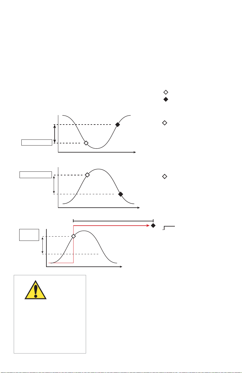
Hysteresis
Time
High Setpoint
Process
Relay energized
Relay de-energized
Hysteresis
Time
Low Setpoint
Process
24. Relay and Open Collector Outputs - continued
The DPU91 open collector and relays are selectable and confi gurable and can be used
as switches that respond when the process value moves above or below a user-defi ned
setpoint or it can be used to generate a pulse at a rate proportional to the process value.
They can be used for Low Alarm, High Alarm or Proportional Pulse triggering related to
the process value. All relay functions are set up in the RELAY menus.
Open Collector Output
Longer life than a mechanical relay
No moving parts
Faster ON/OFF switching than mechanical relays
Can switch DC voltage only (< 30 VDC)
Not recommended for use with inductive loads
Low Setpoint:
Relay is on when the
measured value is
less than the setpoint.
High Setpoint:
Relay is on when the
measured value is
higher than the setpoint.
Process
High
Setpoint
Hysteresis
If power is lost to the DPU91
Transmitter during a cycle,
the Cycle Time will reset.
If the condition still exists
after power is restored,
the relay will be energized
for the complete Cycle Time.
OMEGA DPU91 Transmitter30
CAUTION
Cycle Time
Cycle High/Low:
The relay can stay
energized for a set length
of time after the process
value goes above
(or below) the setpoint.
Time
The relay will stay on for the CYCLE TIME and then turn
off, even if the process value is still above (or below) the
setpoint. The cycle will not repeat until the process value
goes below (or above) the setpoint minus the hysteresis
after the relay times out.
In FLOW, Cycle High activates the relay each time the
volume reaches the SET VOLUME setpoint (see page 40).
NOTE:
To reset the timer (or volume in Flow): in the RELAY menu,
select TEST RELAY function. The timer will reset to 0 if the
condition no longer exists when the TEST is performed.
The timer will restart if the condition still exists.
Page 31
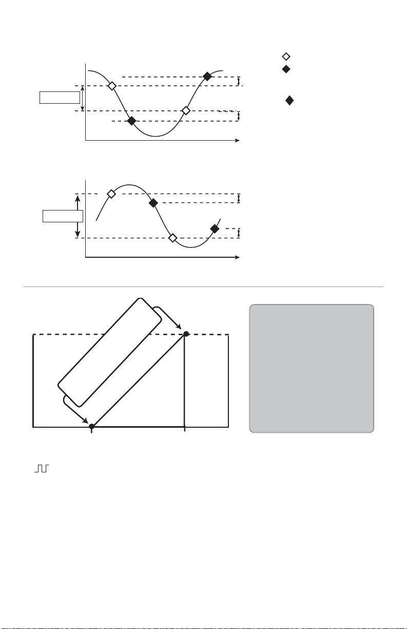
Time
High Limit
Hysteresis
Low Limit
Process
Window
Relay energized
Relay de-energized
Time
High Limit
Hysteresis
Low Limit
Process
Window
Hysteresis
24. Relay and Open Collector Outputs - continued
10
5
Open Collector Output Rate:
0 to 100 Pulses/min.
Pulse rate
0 pulses
100 puls
Window IN example
Window OUT example
Window In/Out:
Relay is on when the value
is higher or lower than the
high or low setpoint.
WINDow IN =
relay on if measurement is
inside the window of two
setpoints. Measurement
inside the two setpoints
is abnormal condition.
WINDow OUT =
relay on if measurement
is outside the window of
two setpoints.
Proportional Pulse Operation:
The transmitter can output a pulse at the rate defi ned by the settings in the CAL menu and
the sensor input. The maximum pulse output from the relays is 300 pulses per minute.
Example usage would be to control solenoid-operated dosing pumps.
For example:
As the process value drops below the setpoint, the output will start pulsing in relation to the
process value, the maximum pulse endpoint and the programmed pulses/minute.
The pulse rate will change as the process value changes and approaches the
programmed endpoint. This functionality can be used to precisely control the process.
The starting point, endpoint, and maximum pulse rate are select able in the RELAY menus.
NOTE: Relay LEDs are not lit in PULSE mode.
100 pulses
Starting point Endpoint
In the example:
• The output will be
0 pulses/min. when
value is less than 5.
• The output will be
50 pulses/min. when
value is 7.5.
• The output will be
100 pulses/min. when
value is greater than 10.
31OMEGA DPU91 Transmitter
Page 32
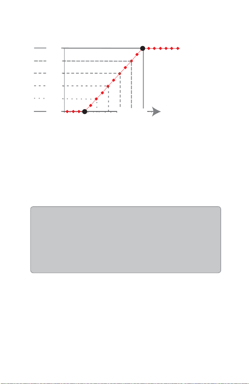
y
24. Relay and Open Collector Outputs - continued
PWM
Maximum
100%
80%
60%
40%
Relay Pulse Width
(as a % of Relay period)
20%
Range
Relay is
always ON
0%
alwa
Relay is
s OFF
PWM
Minimum
Process value
• Pulse Width Modulation
PWM automatically varies the ratio of ON time to OFF time proportional to minimum and
maximum range settings.
The relay period is the sum of the time a relay is ON and the time it is OFF.
Relay pulse width is the time the relay is ON.
The DPU91 must be programmed with the relay period, and with the low and high setpoints.
NOTE: The PWM mode is not used for Pressure applications.
NOTE: Relay LEDs are not lit in PWM mode.
Example:
• The pulse width will be 0% of the relay period (relay always OFF)
when the process value is less than the minimum range.
• The pulse width will be 100% of the relay period (relay always ON)
when the process value is greater than the maximum range.
• The pulse width will be 60% of the relay period when the process value
is at 60% of the span between the minimum and maximum range.
OMEGA DPU91 Transmitter32
Page 33
24. Relay and Open Collector Outputs - continued
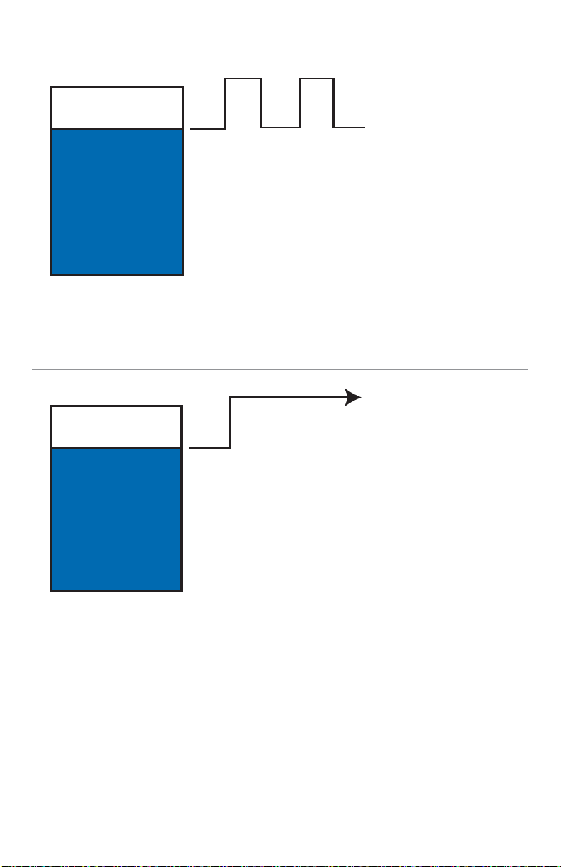
• Volumetric Pulse
A pulse is generated each time a specifi ed volume of fl uid is registered.
For fl ow inputs only.
NOTE: Relay LEDs are not lit in VOLUMETRIC PULSE mode.
• Totalizer Volume
Relay activates and latches when a specifi ed volume of fl uid is registered.
For Flow inputs only.
Total Volume mode counts the TOTALIZER Units until the setpoint volume is reached,
then turns on the relay until the resettable totalizer is reset.
If the Resettable Totalizer reading is greater than the setpoint, the relay will be turned
on immediately. The relay will be off when the totalizer is reset to zero.
This mode is useful to trigger a reminder when a process is due, as for a backwash
cycle or fi lter change.
33OMEGA DPU91 Transmitter
Page 34
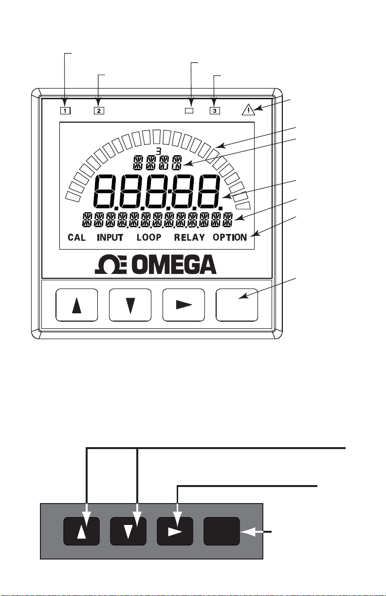
25. Operation
Open Collector (R1)
Indicator LED
Mechanical Relay (R2)
Indicator LED
Backlight Sensor
(do not block)
Mechanical Relay (R3)
Indicator LED
Warning LED
Bar Graph
Units of Measure
(GPM, pH, sec, %, etc.)
Value
Label
Menu Indication
®
Menu
Navigation
Keys
ENTER
All possible segments shown in this illustration.
The instrument's software controls which segments are shown at any particular time.
Only the bar graph and Omega logo are visible when the unit is turned off.
3
Warning LED will be lit when No Sensor or Wrong Sensor is detected in Digital (S
L) mode.
UP, DOWN keys
Scroll through Menu options or adjust values during editing
Press both together to exit a menu or escape without saving
RIGHT key
Select item or character to edit
ENTER key
ENTER
Access menus
Save changes
OMEGA DPU91 Transmitter34
Page 35
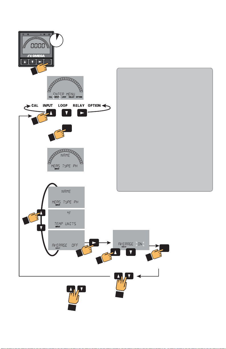
25. Operation - continued
3s
®
ENTER
Keypad Functions
The four buttons of the keypad are used to navigate
display modes according to the descriptions in this table.
Notice that the function of each button may change
depending on the display mode.
Edit
or or
ENTER
(Password may
be required)
Input Edit
Input Edit Choices
System Setup: Menu Navigation
This basic operating procedure repeats
throughout the DPU91 program:
1. Press ENTER for 3 seconds to enter
MENU mode.
2. Press to move to the desired
menu then press ENTER to select it.
(Password may be required.)
3. Press or to select the desired
menu item for editing.
4. Press to edit the value/selection.
5. Press ENTER to store the new value.
6. Press or to select another menu
item. Repeat steps 3-5 as required.
7. Press + to select a different
menu to edit.
Repeat steps 2-5 as required.
8. When fi nished editing, press +
again to return to normal operation.
The menu is constructed in a loop, so you can
move forward and backward to select an item.
After any item is saved (by pressing ENTER),
the display will return to the previous menu.
+
Return to
View Mode
2x
or
ENTER
Saves Changes
+
Or
Select another
Menu Item
35OMEGA DPU91 Transmitter
Page 36
26. Menu System
System Setup Menu
All of the basic system setup functions are automated in the DPU91 for many sensors
and sensor electronics. This includes identifying the sensor connected to the DPU91,
and confi guring the display for the sensor. After installation and wiring is completed,
apply power to the DPU91.
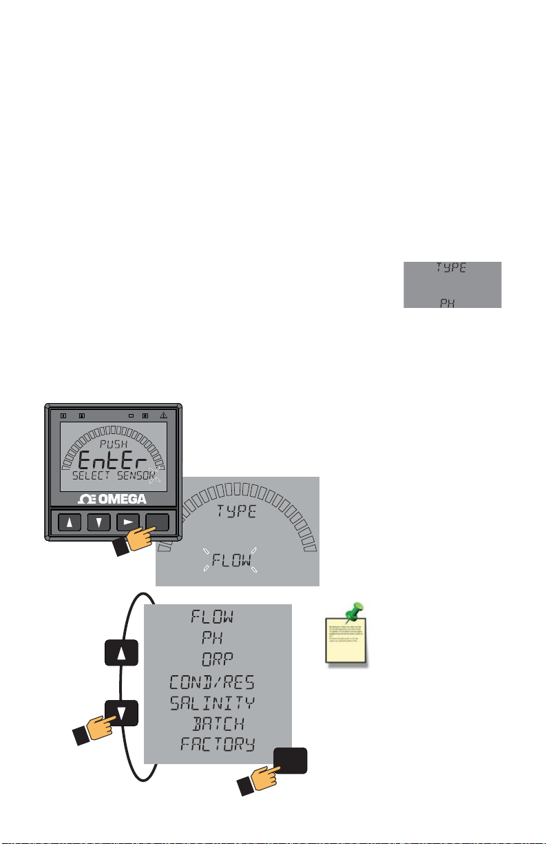
When the DPU91 is fi rst powered on, it will attempt to determine the sensor type
connected when ENTER is pressed (display will display LOOKING FOR).
If no sensor is attached to the DPU91, the words “TYPE” and “FLOW” are displayed.
When a sensor is attached, the DPU91 will attempt to determine the instrument type.
If the DPU91 does not identify your sensor type, use the and keys to scroll through
the available sensor types.
As you scroll through the available sensor types, press to select the desired sensor
and then press ENTER.
You may change sensor type after initial power-on
(if sensor type is changed after your DPU91 is already in service).
Enter the INPUT menu, scroll to TYPE, press , and scroll to select
the desired sensor type (you may be prompted for your password). Press ENTER.
The bottom line will display ALL SETTINGS WILL BE RESET. ARE YOU SURE?
The top line of the display will blink NO (unless switching from Factory mode).
Press or to select YES. Press ENTER again to finalize your selection.
CAUTION:
Omega strongly discourages
changing the sensor type away
from the correct sensor.
®
ENTER
Sensor Choices
NOTE:
The DPU91 displays the
BATCH instrument type ONLY if
the Batch Module is installed.
ENTER
OMEGA DPU91 Transmitter36
Page 37

26. Menu System - continued
VIEW Mode Overview
The top level of menus is referred to as the VIEW Mode.
This view displays measurement values as well as current outputs and relay status.
The radial bar graph represents the measurement value that is also displayed in the
7-segment numeric fi eld below the bar graph. The bar graph is primarily used to display
the full scale range of the sensor, but can be scaled via a menu item.
During normal operation, the DPU91 displays the VIEW mode.
To select a display, press the or arrow keys.
The display selections scroll in a continuous loop.
Changing the display selection does not interrupt system operations.
No password is necessary to change display selection.
Output settings cannot be edited from the View Mode.
The display will return to the VIEW mode if no button is pressed for 10 minutes.
Error Handling
Errors occurring while in the VIEW Mode show a specifi c message (e.g., CHECK SENSOR).
This message is displayed every 10 seconds and stays on for 5 seconds.
Once the error is resolved or cleared, the error message stops.
Scrolling
In some cases, more than one message or measurement may need to be displayed.
This is accomplished by alternating the message portions across the screen.
MENU Mode Overview
The MENU mode enables the user to view and confi gure all menu items.
The fi ve menus available are: CAL, INPUT, LOOP, RELAY, and OPTION.
MENU Mode is entered by pressing and holding ENTER for three seconds.
The button is used to change the position of the blinking cursor.
When the desired menu is blinking, press ENTER.
In the selected menu, use the and keys to navigate through the menu.
Use the , and keys to edit the selected item (see Menu Navigation, page 35).
To save the new selection, press the ENTER key.
A message displaying “Saving…” will be displayed for 3 seconds.
After this message is displayed, the newly selected value will be displayed, if applicable.
37OMEGA DPU91 Transmitter
Page 38
26. Menu System - continued
Password Overview
The password is often required to start editing. Once entered correctly, this password
will not be needed for subsequent edits. However, once the menu system is exited,
the password will again be required when edit mode is re-entered.
Your choice of password (STD or CODE) is selected in the Options Mode.
STD
The standard (STD) password is , pressed in sequence. This password
is designed to protect the DPU91 from unintentional changes. It is best suited for
systems where a group of people need to be able to change settings.
CODE
The CODE default setting is 0000, adjustable to any 4-digit numerical code up to
9999. Using a personal code provides the maximum degree of security.
This code can be modifi ed in the Options mode.
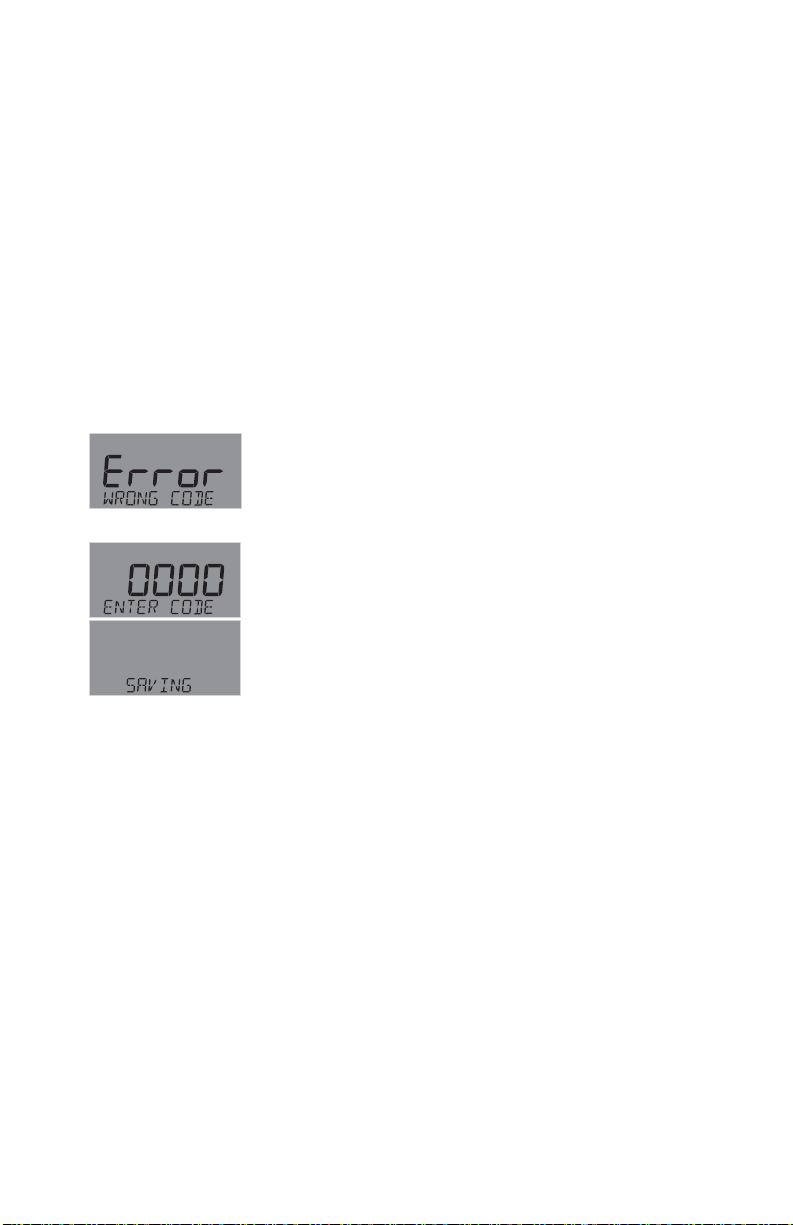
In the MENU mode, if the wrong code or password
is entered, an ERROR message is displayed.
To change your CODE, go to OPTIONS mode,
enter your desired code and press ENTER.
(The STD password cannot be changed.)
OMEGA DPU91 Transmitter38
Page 39
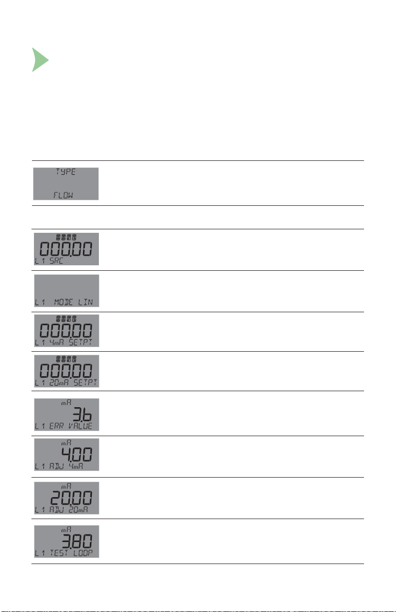
27. Common Menus
System Start-up: Step 4
Customize your DPU91 to your own installed sensors.
Common Menus
The menu system shares certain modes between sensor types.
The following describes the EDIT Mode menus common between most sensor types.
NOTE:
Menu and Mode displays shown are examples only. Your displays may vary.
INPUT Menu
(ALL) Manually select Sensor Type (See page 36 for instruction).
Allows user to reset DPU91 Transmitter to Factory settings.
NOTE: Omega strongly discourages changing the sensor type away
from the correct sensor.
LOOP1 Menu
(pH, COND/RES, SALINITY only) Set LOOP1 output source:
Select either Primary or Secondary measurement of applicable sensor.
Secondary measurements: pH, COND/RES, and SALINITY = TEMP
(COND/RES only) Select LIN/LOG. Default = LIN.
See LOG Current LOOP Output discussion in Appendix.
(ALL) Set value corresponding to desired 4 mA output. 5 digits max.
Default = 0 (ORP = -999).
(ALL) Set value corresponding to desired 20 mA output. 5 digits max.
(Not shown in COND/RES LOG Mode.)
Defaults = 100 (Flow, Cond/Res), 14 (pH), 1000 (ORP), 80 (Sal).
(ALL) Set desired LOOP1 output value when sensor error
(e.g., bad sensor, broken wire) is detected.
Select (3.6 mA, 22 mA). Default = 22.
(ALL) Allows fi ne-tuning to compensate for errors in other equipment
connected to the DPU91. Adjust the maximum current output. The
display value represents the precise current output. Adjustment limits:
from 3.80 mA minimum to 5.00 mA maximum. Default = 4.00 mA.
(ALL) Allows fi ne-tuning to compensate for errors in other equipment
connected to the DPU91. Adjust the maximum current output. The
display value represents the precise current output. Adjustment limits:
from 19.00 mA minimum to 21.00 mA maximum. Default = 20 mA.
(ALL) Press or to manually order any output current value from
3.8 mA to 21.00 mA to test the output of LOOP1.
39OMEGA DPU91 Transmitter
Page 40
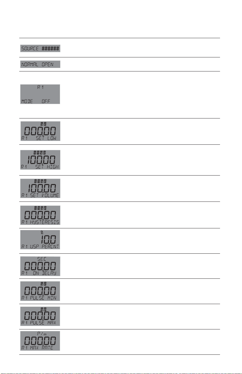
27. Common Menus - continued
RELAY Menu
(pH, COND/RES, SALINITY only)
Select source for each of R1, R2 and R3 outputs.
Choose pH/TEMP, COND/TEMP, SAL/TEMP.
(ALL) Set Open Collector (R1) as Normally Open or Normally Closed.
Default = OPEN.
(ALL) Select the desired mode of operation for the open-collector (R1)
output (OFF, LOW, HIGH, WINDow IN, WINDow OUT, CYC LOW
(except FLOW), CYC HIGH, PROP PuLSe, VOL PuLSe, PWM,
TOTAL, USP, ERROR mode) (See chart on next page). Default = OFF.
Continue stepping through to select R2 and R3 output modes. When
MODE is set to ERROR, delays energizing relay until after ON DELAY
time expires if sensor problem is detected.
See Cycle High/Low discussion on page 30.
(ALL) Relay turns on if process measurement goes lower than this value.
Set desired value (Shown if LOW, WIND IN/OUT or CYC LOW mode).
NOTE: The indicator lights do not light up in PROP PLS and PWM modes.
The LEDs light up only when the Test Relay options are selected.
(ALL) Relay turns on if process measurement goes higher than this value.
Set desired value (Shown if HIGH or WIND IN/OUT mode).
NOTE: The indicator lights do not light up in PROP PLS and PWM modes.
The LEDs light only when the Test Relay options are selected.
(FLOW only)
before a pulse is sent out.
value. Set desired value (Shown if CYC HIGH or VOL PLS mode).
Default = 100.00.
(ALL) Hysteresis prevents the system from chattering around the set
point. Set amount (in units of measure from INPUT Mode) to add to
SET LOW or SET HIGH values.
(Shown if LOW, HIGH, WIND IN/OUT, CYC LOW/HIGH or USP mode)
Amount of accumulated fl ow that must be counted
Defaults = pH, COND, SAL.
Relay turns on if fl ow volume exceeds this
(COND/RES only)
Relay turns on if USP value drifts by this value away from USP limit.
(Shown only in USP mode) See Appendix for USP Limits discussion.
(ALL) Set seconds (up to 9999.9) to wait before activating relay.
(Shown if Low, High, WIND IN/OUT, CYC LOW/HIGH or Error mode.)
(ALL) Set minimum setpoint value for proportional pulsing.
(Shown if PROP PLS mode.)
(ALL) Set maximum setpoint value for proportional pulsing.
(Shown if PROP PLS mode.)
(ALL) Set desired maximum pulse rate (300 max)
(Shown if PROP PLS mode.) NOTE: Pulse width fi xed at 100 ms.
OMEGA DPU91 Transmitter40
Page 41
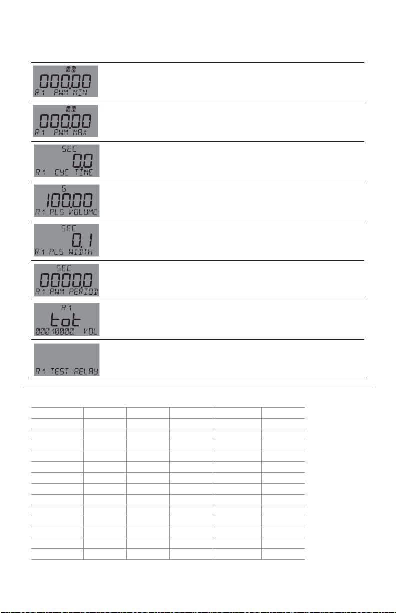
27. Common Menus - continued
RELAY Menu - Cont.
(ALL except FLOW)
Set minimum value for pulse width modulation (Shown if PWM mode).
(ALL except FLOW)
Set maximum value for pulse width modulation (Shown if PWM mode).
(ALL) Set time in seconds (up to 99999) for relay to remain on.
See discussion on page 30. (Shown if CYC LOW/HIGH mode.)
(FLOW only) Amount of accumulated fl ow that must be counted before
a pulse is sent out. Set value. (Shown only if VOL PULS.)
(FLOW only) Set time value for one pulse width.
(Shown only if VOL PULS.)
(ALL except FLOW) Set time value for one complete pulse cycle
(relay ON time + relay OFF time). (Shown if PWM mode)
(FLOW only) Resettable value that, when exceeded, turns relay on.
Must reset Totalizer (in VIEW Mode) to clear relay.
Set maximum value (Shown only if TOTAL.).
(ALL) Press or to turn relay on or off for testing purposes.
Can also be used to reset or latch/unlatch the relay.
Does NOT reset the Totalizer.
Available Relay Modes by Sensor Type
Flow pH ORP Cond/Res Salinity
OffXXXXX
Low X X X X X
High X X X X X
Wind In X X X X X
Wind Out X X X X X
Cyc Low X X X X
Cyc High X X X X X
Prop Pulse X X X X X
Vol Pulse X
PWM X X X X
Total X
USP X*
Error X X X X X
* In USP Relay Mode in Conductivity, Relay Source must be set to COND, TEMP COMP must
be set to NONE and Unit Of Measure must be set to S.
41OMEGA DPU91 Transmitter
Page 42
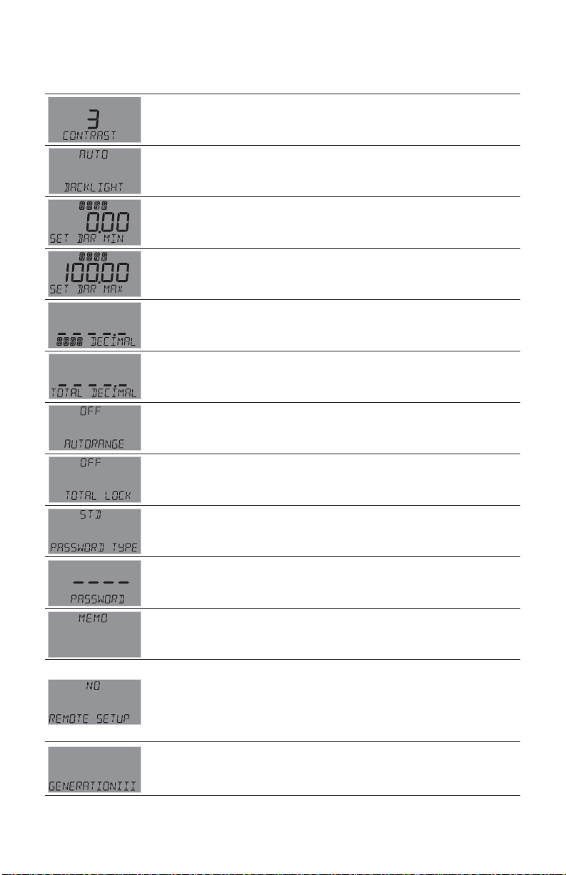
27. Common Menus - continued
OPTION Menu
Adjust the LCD contrast for best viewing for your environment.
A setting of 1 is lowest contrast, 5 is highest. Default = 3.
Select backlight level (OFF, LOW, HIGH, AUTO).
Default = AUTO. NOTE: No backlight when operating on loop power.
Enter 5 digit value to represent bar at minimum.
Default = 0 (ORP = -999).
Enter 5 digit value to represent bar at maximum.
Defaults = 100 (Flow, Cond/Res), 14 (pH), 1000 (ORP), 80 (Sal)
(ALL) Set the decimal to the best resolution for your application.
The display will automatically scale up to this resolution.
Select -----., ----.-, ---.-- or --.---. Default = ----.-.
(FLOW only)
Totalizer display. The display will automatically scale up to this resolution.
Select -----., ----.-, ---.-- or --.---. Default = ----.-.
(COND/RES only)
Displays mS or S as set in COND UNITS in INPUT Mode.
Set ON/OFF.Default = OFF.
(FLOW only)
Locks the TOTALIZER output. Select OFF, ON (Does not affect
Permanent Totalizer). Default = OFF.
(ALL) Select STD, CODE. Default = STD.
(ALL) Enter desired password code.
4-character entry not displayed, ---- displayed instead.
(Shown if type = CODE.)
(ALL) Enter 13-character string, if desired. Default = Blank.
Enables Remote Setup to confi gure the DPU91 via a computer and the
optional PC COMM tool. Press and select YES to enable.
REMOTE SETUP flashes when mode is enabled.
NOTE: Communication with PC COMM tool is automatic when the
DPU91 is in FACTORY state (Enter flashing).
Refer to the DPU90-CT PC COMM Tool manual.
Displays Transmitter Generation Version.
Set the decimal to the best resolution for the Permanent
OMEGA DPU91 Transmitter42
Page 43
28. Sensor-Specifi c Menus
The following pages list the sensor-specifi c settings for each sensor type.
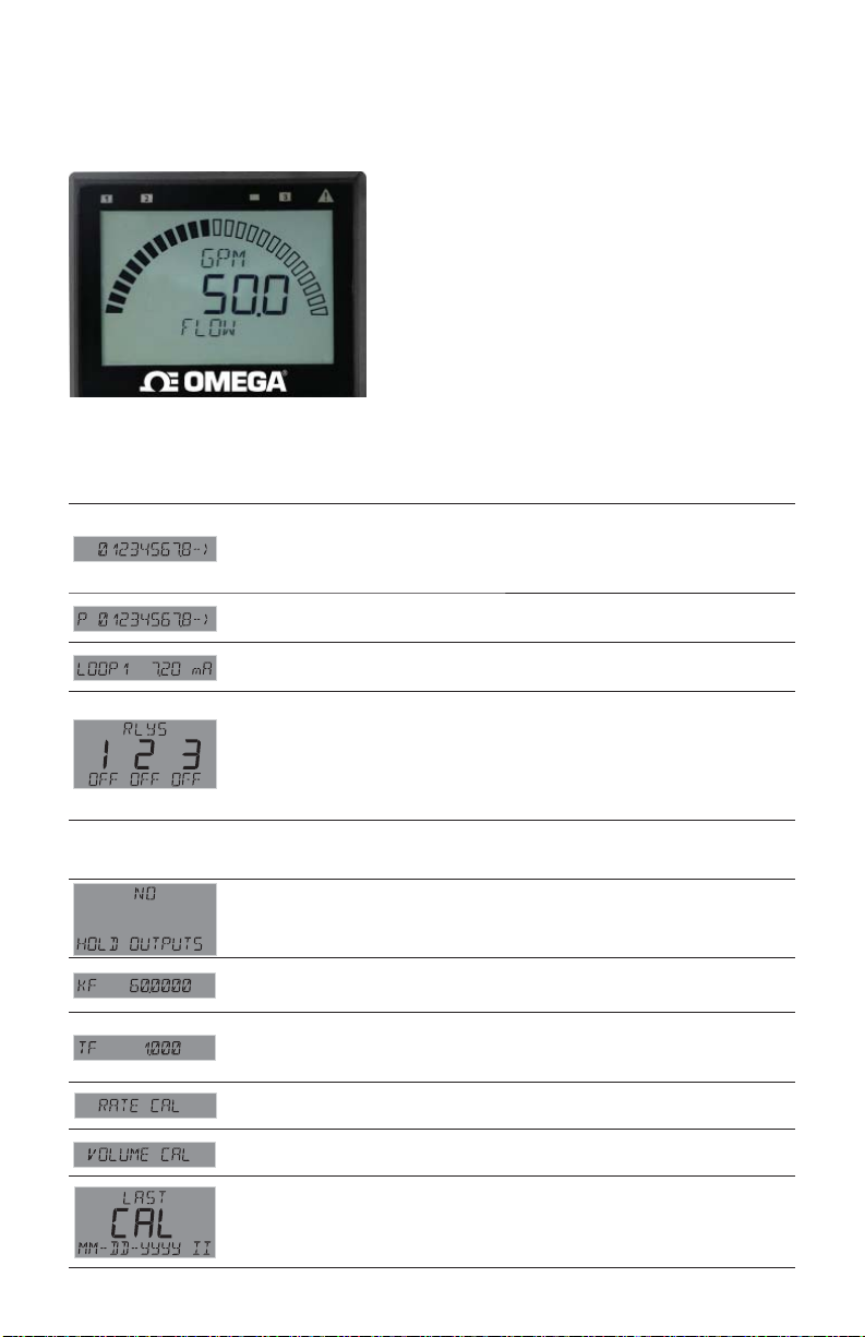
Flow
FLOW Setup Checklist
1. Make sure FLOW sensor type is selected
(see System Setup Menu, page 36).
2. Set the Units of Measurement.
3. Set Sensor Type (Freq or S
4. If LOOP is used, set the minimum and
maximum 4 to 20 mA setpoints.
5. Set K-Factor (pulses per Unit Volume)
from Flow Sensor manual.
6. Set Totalizer factor.
This is the normal display
and does not time out.
7. Set Last Cal Date and initials.
8. If desired, set up relay functions for your
own application.
VIEW Mode Menu
Display the fl ow rate and the resettable totalizer.
Press to reset the totalizer (If Reset is locked, enter the password fi rst).
Lock or Unlock the totalizer in the OPTIONS menu.
This is the resettable totalizer View display.
Display the Permanent Totalizer value (note the "P" indicating Permanent).
Pressing displays units of measure.
Displays the 4 to 20 mA LOOP1 output.
Bottom line shows one of three states (OFF, ON, PLS) for each of the three
relays. Displays remaining time for CYC LOW or CYC HIGH mode.
The relay(s) will remain ON while counting down.
NOTE: To reset the timer: In the RELAY menu, select TEST RELAY function.
The timer will reset to 0 if the condition no longer exists when the TEST is
performed. The timer will restart if the condition still exists.
3
L).
CAL Menu
YES prevents relays from activating while making adjustments, and
relays in PULSE mode will suspend pulsing. Output is held until the
user exits the CAL menu. Select YES/NO. Default = NO.
Set K-Factor (pulses per unit volume) from Flow Sensor manual.
Min: 0.0001, max 999999. Cannot be zero. Default = 60.0000.
Sets the volume of each count of the Totalizer as a multiple of the
volume unit of the K-Factor.
Min: 0.0001, max 999999. Cannot be zero. Default = 1.0000.
Select to calibrate using Rate method (see Appendix).
Select to calibrate using Volume method (see Appendix).
Enter date of calibration (mm-dd-yyyy) and initials of calibrator (ii).
43OMEGA DPU91 Transmitter
Page 44
28. Sensor-Specifi c Menus
Flow - continued
INPUT Menu
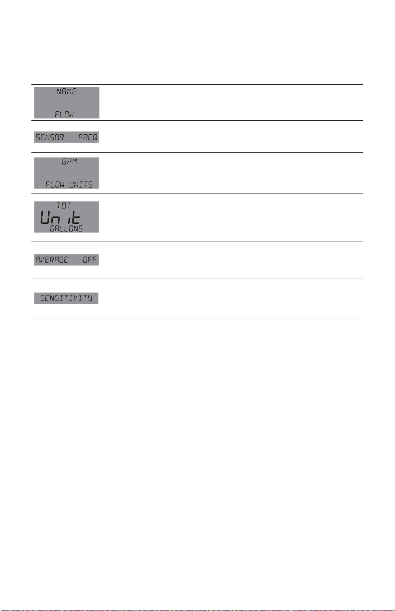
If desired, a custom name can be entered.
Enter 13-character string. Default = FLOW.
If your fl ow sensor is confi gured for frequency output, select FREQ.
If confi gured for Digital (S
Default = FREQ.
Set the units of measure. The last character sets the timebase:
S (seconds) M (minutes) H (hours) D (days). Default = GPM.
Identifi es the Totalizer units. It has no effect on any calculation.
Default = GALLONS.
Dampens display, output and relay response rates.
Select Low, Med, High, OFF (See discussion in Appendix).
Default = OFF.
Acts as a threshold for fl ow measurement response. A lower sensitivity
setting gives a fast measurement response, a higher setting gives a slower
response. Value expressed in units of measurement; response dependent
on units of measurement being exceeded. (See discussion in Appendix.)
3
L) output (recommended), select S3L.
OMEGA DPU91 Transmitter44
Page 45
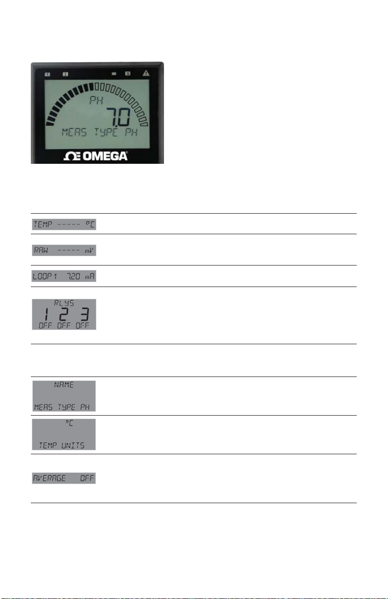
28. Sensor-Specifi c Menus
pH
This is the normal display
and does not time out.
VIEW Mode Menu
Displays temperature at the sensor.
Displays the millivolt input from the electrode. Use this display to
determine the relative condition of your electrode during periodic
calibration. (7 pH buffer = 0 mV, ± 50 mV)
Displays the 4 to 20 mA LOOP1 output.
Bottom line shows one of three states (OFF, ON, PLS) for each of the three
relays. Displays remaining time for CYC LOW or CYC HIGH mode.
The relay(s) will remain ON while counting down.
NOTE: To reset the timer: In the RELAY menu, select TEST RELAY function.
The timer will reset to 0 if the condition no longer exists when the TEST is
performed. The timer will restart if the condition still exists.
pH Setup Checklist
1. Make sure pH sensor type is selected
(see System Setup Menu, page 36).
2. Set the Temperature Units (°C or °F).
3. If LOOP is used, set the minimum and
maximum 4 to 20 mA setpoints.
4. Perform calibration (EasyCal, Standard
or Standard and Slope).
5. Set Last Cal Date and initials.
6. Select source for Open Collector and
Relay output (pH or Temp).
7. If desired, set up relay functions for
your own application.
INPUT Menu
Enter string up to 13 characters (optional).
Default = MEAS TYPE PH.
Select °F or °C.
Default = °C.
Dampens display, output and relay response rates.
Select Low, Med, High, OFF (see discussion in Appendix).
Default = OFF.
NOTE: Omega strongly recommends leaving averaging OFF for pH and
Pressure measurements (see discussion in Appendix).
45OMEGA DPU91 Transmitter
Page 46
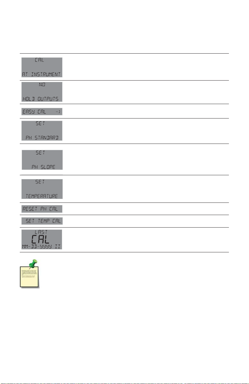
28. Sensor-Specifi c Menus
pH - continued
CAL Menu
Select AT SENSOR to perform calibration using the PHEH-275
sensor electronics. Select AT INSTRUMENT to perform calibration at
the DPU91 via EasyCal or manual calibration. (See pH Calibration
procedures in the Appendix.) Default = AT INSTRUMENT.
YES prevents relays from activating while making adjustments, and
relays in PULSE mode will suspend pulsing. Output is held until the
user exits the CAL menu. Select YES/NO. Default = NO.
Press to start the EasyCal process. You will be prompted to enter
your password. (See pH EasyCal procedure in the Appendix).
Applies a linear offset to the pH measurement. The ideal value is the
average pH of your application. (A sample of your application at process
temperature is recommended.) (See pH Calibration procedures in the
Appendix.) Shows error message if offset too high.
Applies a slope to the pH measurement.
The slope value and the standard value must be at least 2 pH units apart.
The ideal values are the minimum and maximum values of your process.
(See pH Calibration procedures in the Appendix.)
Shows error message if slope is too low or high.
Applies a linear offset to the temperature measurement.
The ideal value is the average temperature of your application.
"SAVING" will appear if offset is acceptable,
"ERR TOO LARGE TO CALIBRATE" if offset is outside of range.
Press to reset pH Calibration to factory default.
Press to reset temperature calibration to factory default.
Enter date of calibration (mm-dd-yyyy) and initials of calibrator (ii).
NOTE: If CAL AT SENSOR is selected, the only screens shown
will be CAL, HOLD OUTPUTS, and LAST CAL DATE.
OMEGA DPU91 Transmitter46
Page 47
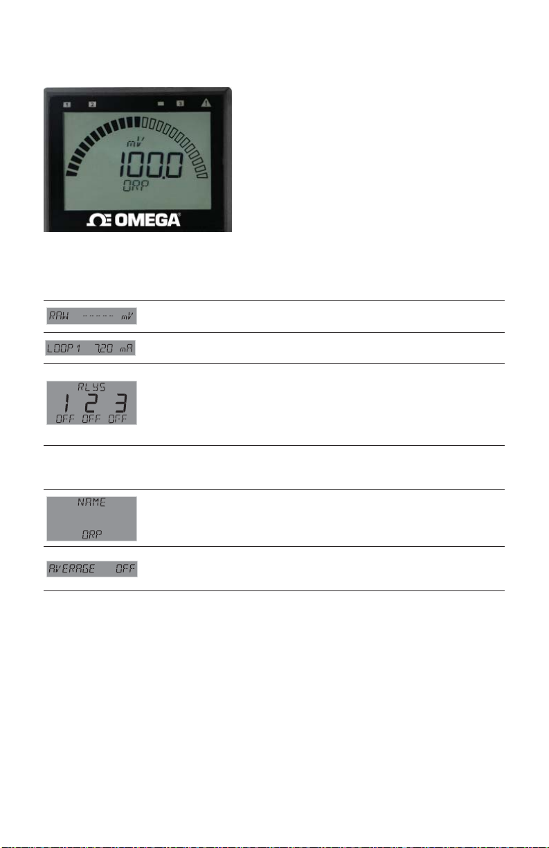
28. Sensor-Specifi c Menus
ORP
This is the normal display
and does not time out.
VIEW Mode Menu
Displays the millivolt input from the electrode. Use this display to determine
the relative condition of your electrode during periodic calibration.
Displays the 4 to 20 mA LOOP1 output
Bottom line shows one of three states (OFF, ON, PLS) for each of the three
relays. Displays remaining time for CYC LOW or CYC HIGH mode.
The relay(s) will remain ON while counting down.
NOTE: To reset the timer: In the RELAY menu, select TEST RELAY function.
The timer will reset to 0 if the condition no longer exists when the TEST is
performed. The timer will restart if the condition still exists.
ORP Setup Checklist
1. Make sure ORP sensor type is selected
(see System Setup Menu, page 36).
2. If LOOP is used, set the minimum and
maximum 4 to 20 mA setpoints.
3. Set Averaging.
4. Perform calibration or set Standard
(and Slope if desired).
5. Set Last Cal Date and initials.
6. If desired, set up relay functions for your
own application.
INPUT Menu
Enter string up to 13 characters (optional). Default = ORP.
Dampens display, output and relay response rates.
Select Low, Med, High, OFF. (See discussion in Appendix.)
Default = OFF.
47OMEGA DPU91 Transmitter
Page 48
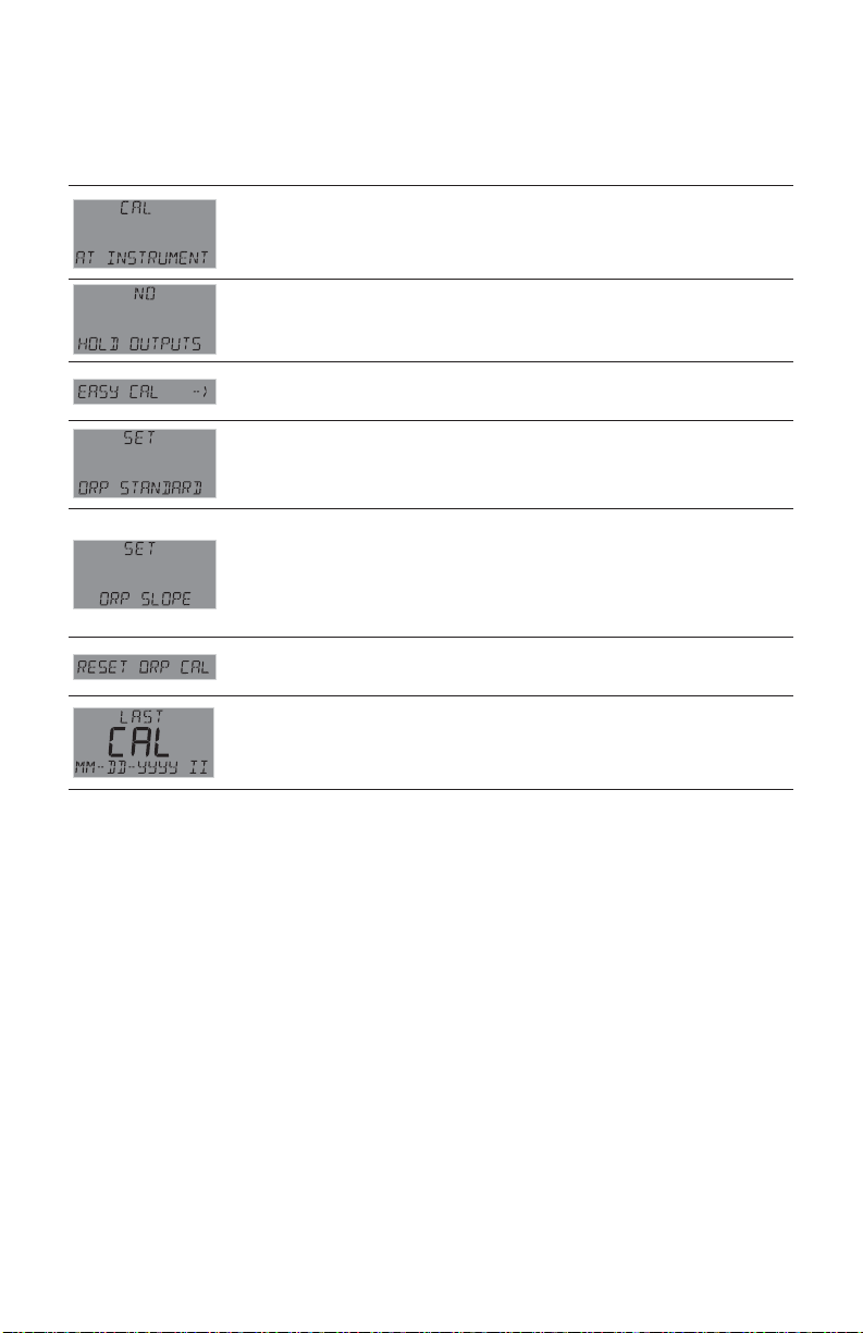
28. Sensor-Specifi c Menus
ORP - continued
CAL Menu
Select AT SENSOR to perform calibration using the PHEH-275
sensor electronics. Select AT INSTRUMENT to perform calibration at
the DPU91 via EasyCal or manual calibration. (See pH Calibration
procedures in the Appendix.) Default = AT INSTRUMENT.
YES prevents relays from activating while making adjustments, and relays
in PULSE mode will suspend pulsing. Output is held until the user exits the
CAL menu. Select YES/NO. Default = NO.
Press to start the EasyCal process. You will be prompted to enter your
password. (See ORP EasyCal procedure in the Appendix).
Applies a linear offset to the ORP measurement. For single point
calibrations, assign the average value of your process to ORP STANDARD.
For two-point calibrations, assign the min or max value of your process to
ORP STANDARD (See ORP Calibration procedures in the Appendix).
Applies a slope to the ORP measurement. The ORP SLOPE is used for
two-point calibration along with the ORP STANDARD. If you applied the
min value of your process to the ORP STANDARD, then apply the max
value to the ORP SLOPE. Else, apply the min value to the ORP SLOPE.
The slope value and the standard value must be at least 30 mV apart. (See
pH Calibration procedures in the Appendix.)
Resets calibration to factory settings. After pressing , select YES/NO.
(Shown if CAL AT INSTR)
Enter date of calibration (mm-dd-yyyy) and initials of calibrator (ii).
OMEGA DPU91 Transmitter48
Page 49
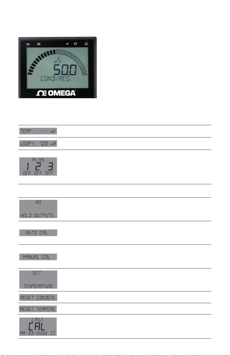
28. Sensor-Specifi c Menus
Conductivity / Resistivity
This is the normal display
and does not time out.
VIEW Mode Menu
Same as above with temperature, does not time out.
Displays the 4 to 20 mA LOOP1 output.
Bottom line shows one of three states (OFF, ON, PLS) for each of the three
relays. Displays remaining time for CYC LOW or CYC HIGH mode.
The relay(s) will remain ON while counting down.
NOTE: To reset the timer: In the RELAY menu, select TEST RELAY function.
The timer will reset to 0 if the condition no longer exists when the TEST is
performed. The timer will restart if the condition still exists.
Cond/Res Setup Checklist
1.
Make sure COND/RES sensor type is selected
(see System Setup Menu, page 36).
2.
Set Cell Constant.
3. Set the Temperature Units (°C or °F).
4.
Set Conductivity units.
5. If LOOP is used, set the minimum and
maximum 4 to 20 mA setpoints.
6. Set Temperature Compensation.
7.
Set Last Cal Date and initials.
8. Select source for Open Collector and Relay
output (COND or TEMP).
9. If desired, setup relay functions for your own
application.
CAL Menu
YES prevents relays from activating while making adjustments, and
relays in PULSE mode will suspend pulsing. Output is held until the
user exits the CAL menu. Select YES/NO. Default = NO.
Shows real-time value and selected standard. “PLACE SENSOR
IN STANDARD”. Unit waits until reading is stable; if bad cal, returns
“ERROR, CANNOT DETERMINE STANDARD”.
Refer to buffer values and AUTO CAL Procedure in the Appendix.
Shows “CONDUCTIVITY” on bottom line; when user presses any button
the live value is frozen and the user edits that value.
If bad cal, returns “ERR TOO LARGE TO CALIBRATE”.
See Manual Cal procedure in Appendix.
Shows “TEMPERATURE” on bottom line; when user presses any button
the live value is frozen and the user edits that value. If bad cal, returns
“ERR TOO LARGE TO CALIBRATE”.
Resets Conductivity calibration. After pressing , select YES/NO.
Resets Temperature calibration. After pressing , select YES/NO.
Enter date of calibration (mm-dd-yyyy) and initials of calibrator (II).
49OMEGA DPU91 Transmitter
Page 50
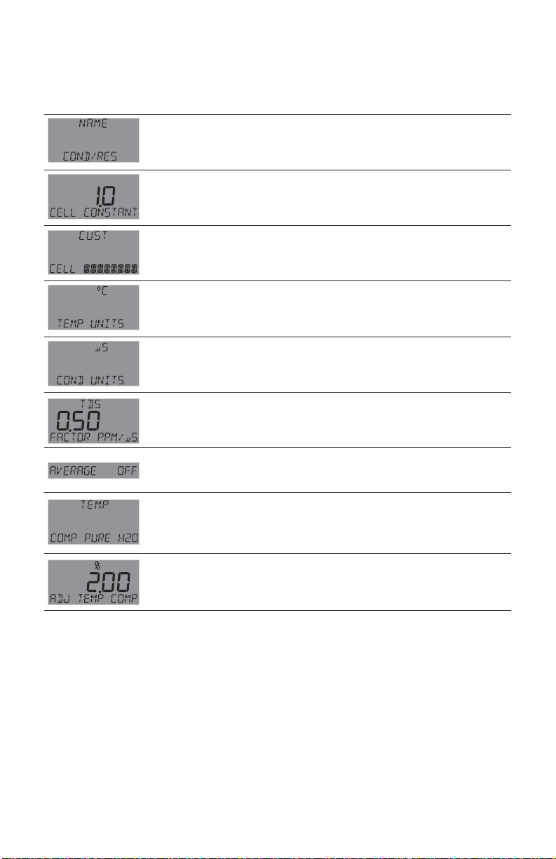
28. Sensor-Specifi c Menus
Conductivity / Resistivity - continued
INPUT Menu
Enter string up to 13 characters (optional).
Default = COND/RES
Enter cell constant of sensor.
Select 20.0, 10.0, 1.0, 0.1, 0.01, or CUSTOM.
Default = 1.0 (See NOTE below)
Enter the precise cell constant from the certifi cate provided with your
sensor, or from the information label on the sensor.
Shown if CELL CONSTANT = CUSTOM. (See NOTE below)
Select °C, °F.
Default = °C
Select S, mS, PPM, PPB, KOhm, or MOhm. Default = S.
NOTE: In USP Relay Mode, TEMP COMP must be set to NONE and
Unit Of Measure must be set to S.
If the COND UNITS selection is PPM or PPB,
set the ratio of Total Dissolved Solids to S. Default = 0.50
Dampens display, output and relay response rates.
Select Low, Med, High, or OFF. (See discussion in Appendix)
Default = OFF
Select temperature compensation (NONE, LINEAR, PURE H2O).
Default = LINEAR. NOTE: In USP Relay Mode in Conductivity, Relay
Source must be set to COND, TEMP COMP must be set to NONE and
Unit Of Measure must be set to S.
For LINEAR or PURE H2O temperature compensation, select a %
per ºC slope. Maximum slope setting is 9.99 % per ºC. Default = 2.0.
(If Temperature Compensation setting is NONE, this item will not be
displayed)
Factory-Set Span:
0.01 cell (CDCE-90-001, CDE-2851) .................... 0 to 100 S
0.10 cell (CDCE-90-01, CDE-2852) ...................... 0 to 1000 S
1.0 cell (CDCE-90-1, CDE-2853) .......................... 0 to 10,000 S
10.0 cell (CDCE-90-10, CDE-2854) ...................... 0 to 200,000 S
20.0 cell (CDCE-90-20B).......................................0 to 400,000 S
NOTE:
If using a CDTX-2850 Conductivity/Resistivity Sensor Electronics in conjunction with
your DPU91, the CDTX-2850 must be set for the custom cell constant or the actual
probe cell constant and the DPU91 set for a 1.0 cell constant.
OMEGA DPU91 Transmitter50
Page 51
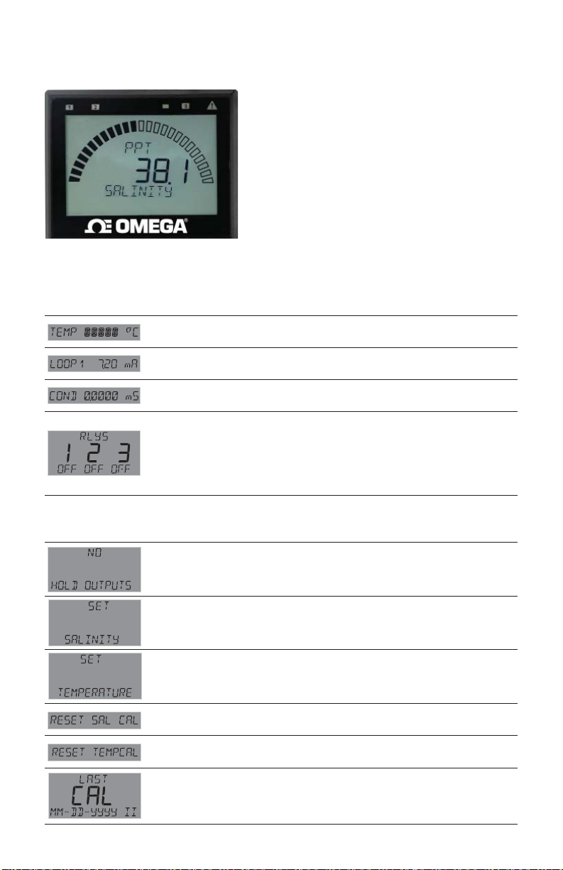
28. Sensor-Specifi c Menus
Salinity
This is the normal display
and does not time out.
VIEW Mode Menu
Displays temperature at the sensor.
Displays the 4 to 20 mA LOOP1 output.
Displays the equivalent conductivity value in milliSiemens.
Bottom line shows one of three states (OFF, ON, PLS) for each of the three
relays. Displays remaining time for CYC LOW or CYC HIGH mode.
The relay(s) will remain ON while counting down.
NOTE: To reset the timer: In the RELAY menu, select TEST RELAY function.
The timer will reset to 0 if the condition no longer exists when the TEST is
performed. The timer will restart if the condition still exists.
SALINITY Setup Checklist
1. Make sure SALINITY sensor type is selected
(see System Setup Menu, page 36).
2. Set Cell Constant.
3. Set the Temperature Units (°C or °F).
4. If LOOP is used, set the minimum and
maximum 4 to 20 mA setpoints.
5. Set Last Cal Date and initials.
6. Select source for Open Collector and Relay
output (SAL or TEMP).
7. If desired, set up relay functions for your
own application.
CAL Menu
YES prevents relays from activating while making adjustments, and
relays in PULSE mode will suspend pulsing. Output is held until the
user exits the CAL menu. Select YES/NO. Default = NO.
Manually set salinity value to match to a known standard
(external reference).
Provides a maximum 20 °C offset to match to a known standard
(external reference).
Resets Salinity calibration to factory settings.
After pressing , select YES/NO.
Resets Temperature calibration to factory settings.
After pressing , select YES/NO.
Enter date of calibration (mm-dd-yyyy) and initials of calibrator (II).
51OMEGA DPU91 Transmitter
Page 52
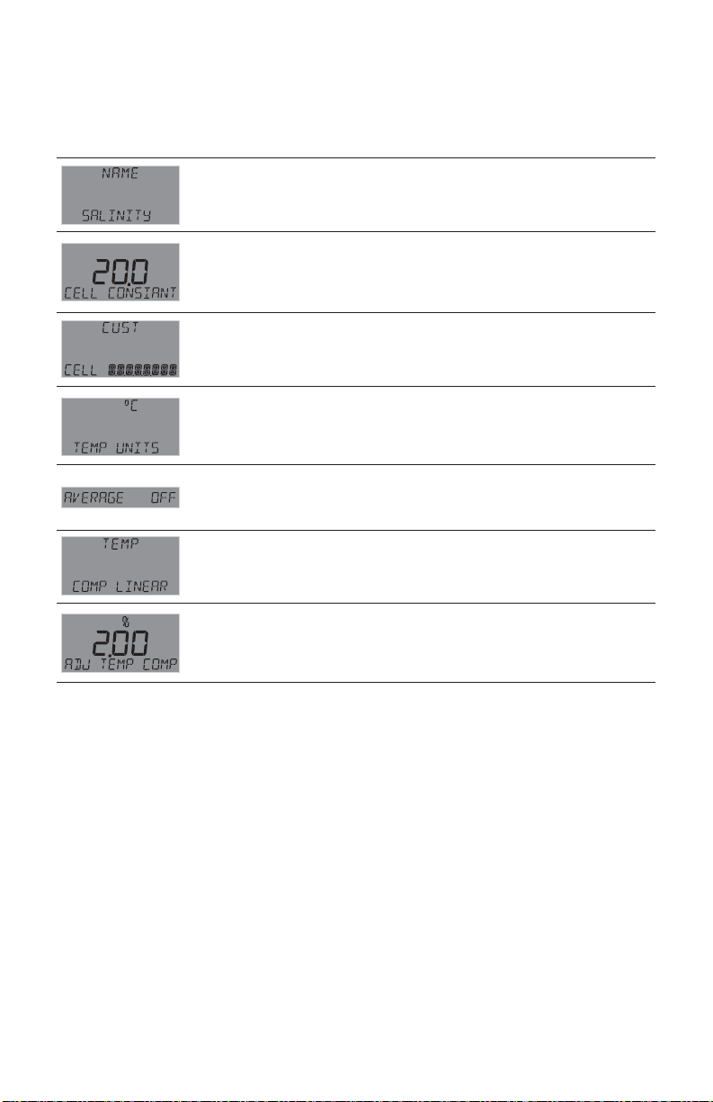
28. Sensor-Specifi c Menus
Conductivity / Resistivity - continued
INPUT Menu
Enter string up to 13 characters (optional). Default = SALINITY.
Enter cell constant of sensor. Select 20.0, 10.0, 1.0 or CUSTOM.
Default = 20.
Enter the precise cell constant from the certifi cate provided with your
sensor, or from the information label on the sensor.
Shown if CELL CONSTANT = CUSTOM.
Select °C or °F.
Default = °C.
Dampens display, output and relay response rates.
Select Low, Med, High, OFF. (See discussion in Appendix.)
Default = OFF.
Select temperature compensation (NONE, LINEAR).
Default = LINEAR.
For LINEAR temperature compensation, select a % per ºC slope.
Maximum slope setting is 9.99 % per ºC. (If Temperature Compensation
setting is NONE, this item will not be displayed.)
OMEGA DPU91 Transmitter52
Page 53

29. Troubleshooting
Condition Possible Causes Suggested Solution
Incorrect sensor installed Connect correct sensor
Wrong Sensor
Wrong Code Wrong password entered
K-Factor Out Of Range K-Factors cannot be set to 0
Backlight inoperative
Relays 2 and 3
inoperative
Relay LEDs inoperative DPU91 operating in Loop Power
Open Collector (R1)
or Relay (R2 or R3)
always on
OVR relay state
(Pulse Overrun)
– – – – –
Check Sensor
Check Preamp DPU91 cannot "talk" to preamp Check wiring or replace preamp
Warning LED lit Look for error message Correct error condition
Sensor Type set incorrectly in
DPU91
DPU91 operating on loop power
Backlight turned OFF
(NOTE: Backlight can turn off
automatically in AUTO mode.)
DPU91 operating on loop power
Relay Module installed
incorrectly
Wrong settings in RELAY menu
Hysteresis value too large Change the hysteresis value
Defective Relay Module Replace Relay Module
Relay pulse rate exceeds
maximum of 300 pulses per
minute
Pulse width set too wide Decrease pulse width
(NOTE: Max pulse rate = 300; max pulse width = 100 mS.
Flow rate exceeds display
capability
DPU91 cannot "talk" to sensor
(pH/ORP, Cond/Res, Sal)
Missing sensor or bad
temperature element
Set correct sensor TYPE in
INPUT menu (see page 36)
Enter correct password
(see page 38)
Enter K-Factor from
0.0001 to 99999
Connect DPU91 to
10.8 to 35.2 VDC power.
Set BACKLIGHT to LOW, HIGH
or AUTO in OPTION menu.
Connect DPU91 to
10.8 to 35.2 VDC power.
Remove and reseat relay
module
Use test relay to verify relay
operation then check relay
settings
Use DC power. Check relay
states in VIEW mode for status.
Increase volume pulse setting
Reduce system fl ow rate
Increase Flow units time base
Change unit of measure
Check wiring
Replace sensor
Install or replace sensor
Missing Cap
Replace Cap
Dissolved Oxygen sensor is
missing the sensor cap
Dissolved Oxygen sensor cap
has expired
Reinstall Dissolved Oxygen
sensor cap
Install new Dissolved Oxygen
sensor cap
53OMEGA DPU91 Transmitter
Page 54
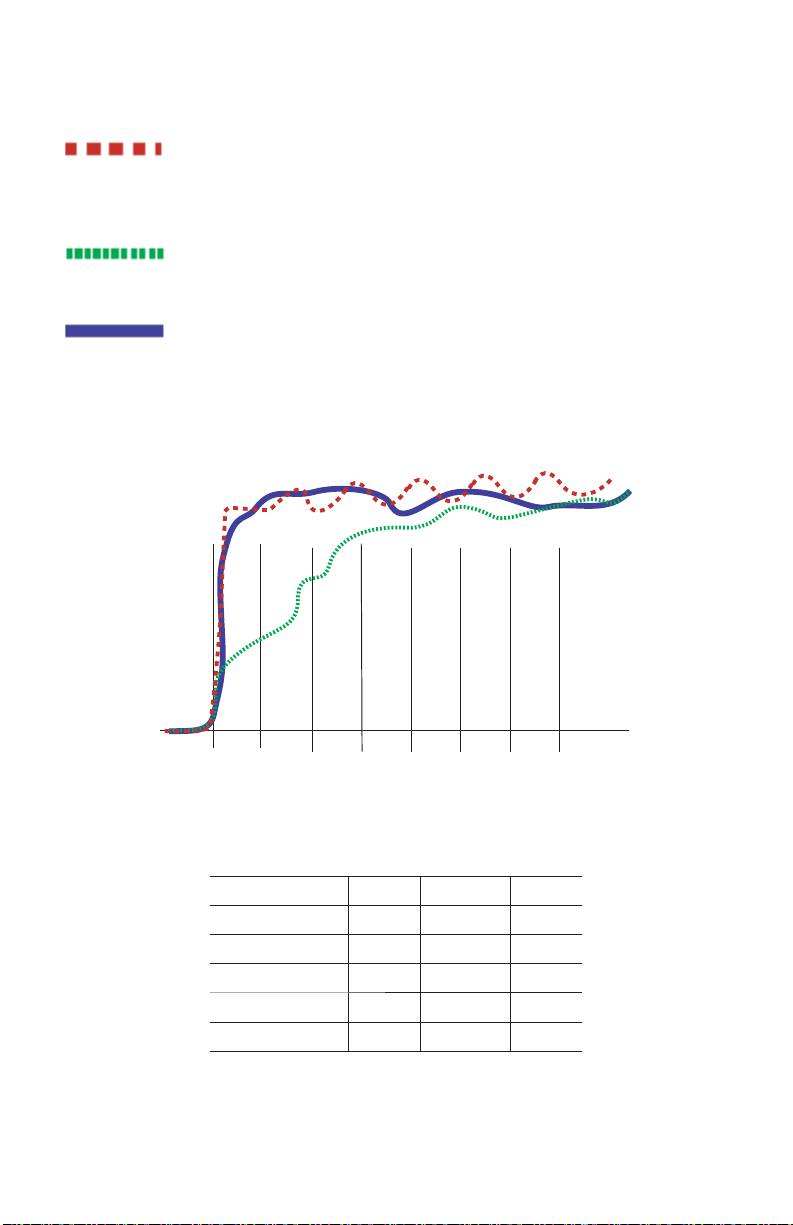
30. Appendix
31. Averaging
NO AVERAGING, NO SENSITIVITY
With SENSITIVITY set to 0 (zero) and AVERAGING set to OFF (0 seconds),
the DPU91 responds immediately to every shift in the process.
The dashed red line represents the actual output of the sensor in varying conditions.
AVERAGING ONLY
With SENSITIVITY still set to zero and AVERAGING set to MED or HIGH the rate is
stabilized, but a sharp change in rate is not represented for 8 to 32 seconds or longer.
AVERAGING AND SENSITIVITY
With SENSITIVITY at 50 and AVERAGING set to MED or HIGH, the rate is
stabilized, while the sudden shift in process is refl ected very quickly.
NOTE: The SENSITIVITY function applies only to FLOW. The SENSITIVITY
function has no effect if the AVERAGING function is set to OFF.
5 s0 s 10 s 15 s 20 s 25 s 30 s 35 s
Averaging is different depending on the measurement type.
Seconds to 99.5% of Final Value for Low, Med, and High are:
Sensor Type Low Medium High
Flow 10 40 120
pH 2 4 12
ORP 2 4 12
Cond/Res 4 6 12
Salinity 4 6 12
OMEGA DPU91 Transmitter54
Page 55

32. LOG Current Loop Output
In Conductivity/Resistivity, the logarithmic (LOG) mode can be used when a very
large measurement range is required, yet high resolution is needed at the low end,
e.g., in a clean-in-place application where a high-resolution conductivity reading
is needed at the low end while a very high conductivity reading is needed when a
cleaning cycle is in progress.
Only two parameters need to be set up, the starting or base conductivity value
(4 mA SETPNT) and the ending or maximum conductivity value (20 mA SETPNT).
The 4 mA setpoint may be larger than the 20 mA point (reverse span).
What equation should be put in the PLC?
Conductivity =
20 mA setpnt
(Log
10
– Log10 4 mA setpnt)
0 × (mA input – 4)
If only fi xed thresholds are of interest, they can be calculated in mA and then the
mA value can be checked directly. Inside the DPU91 the following equation is used:
(Log
mA =
10
– Log
×
Conductivity
4 mA setpnt)
10
16
x
(Log10 20 mA setpnt
+ Log
16
4 mA setpnt
10
+ 4
– Log10 4 mA setpnt)
NOTE :
If ADJUST 4 mA or ADJUST 20 mA is used, the mA value can be affected.
To prevent any problems the adjust function should only be used to get exactly
4.0 and 20.0 at the PLC.
The DPU91 is accurate and the adjust functions are only needed to compensate for
an offset due to noise or a not-so-accurate PLC input card.
The error value of either 3.6 mA or 22 mA should be tested fi rst before applying the
conductivity equation.
55OMEGA DPU91 Transmitter
Page 56
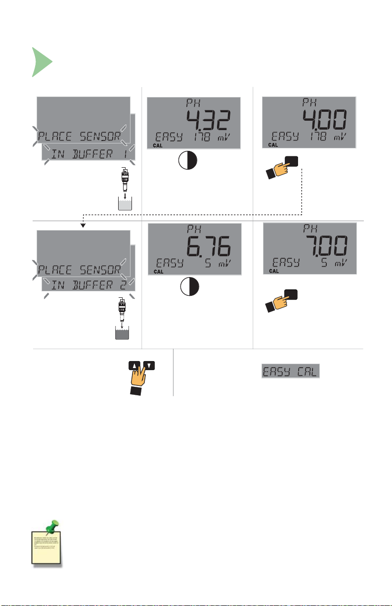
33. Calibration Procedures: pH
EasyCal Procedure - pH
EasyCal is the fastest and simplest periodic calibration method.
Requires prepared 4, 7 or 10 pH buffers (any two).
To Calibrate: Response:
Place electrode tip in
first pH buffer.
pH 4.0 = 177 mV
pH 7.0 = 0 mV
pH 10 = -177 mV
Limit ± 50 mV
Place electrode tip in
second pH buffer.
To exit menus and return to
9,(:SUHVVŸDQGź
buttons at the same time.
1
2
Allow for stabilization
Allow for stabilization
+
30 seconds
30s
30s
30 seconds
Display returns to VIEW
Mode in 10 minutes
To Accept:
ENTER
to accept
to accept second
ENTER
buffer calibration
• This procedure simplifi es pH calibration
using standard 4.0, 7.0, 10.0 pH buffers only.
If these pH buffers are not available,
use MANUAL CAL and calibrate the system
using the STANDARD and SLOPE settings.
• Set sensor temperature in the
CAL Mode before performing
EasyCal for new electrode installations.
NOTE:
The solutions can be used for calibrating more than one sensor;
however, the solution must remain free of debris and must not
be diluted by rinse water from previous calibrations.
OMEGA DPU91 Transmitter56
Theoretical mV values
pH @ 25 °C mV
2 ......................... +296
3 ......................... +237
4 ......................... +177
5 ......................... +118
6 ........................... +59
7 ............................. +0
8 ........................... –59
9 ......................... –118
10 ....................... –177
11 .......................–237
12 ....................... –296
Page 57
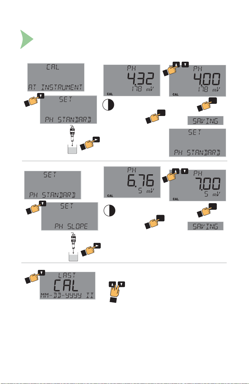
33. Calibration Procedures: pH - continued
Manual Calibration Procedure - pH
Requires prepared buffers. System calibration is possible with two known pH
solutions within 0 to 14 pH (buffers of pH 4.01, 7, or 10 are recommended,
but use a buffer close to your own process value.)
To Calibrate: To Change Reading:
Place electrode tip in
pH buffer.
To Set Slope:
Place electrode tip in
pH buffer two pH units
different than standard.
To Set Calibration Date:
30s
Allow for stabilization
30 seconds to
several minutes
30s
Allow for stabilization
30 seconds to
several minutes
+
Display returns to
VIEW Mode
to accept
to accept
ENTER
To Change Reading:
ENTER
to accept
to accept
ENTER
ENTER
Single-point calibration sets STANDARD only;
Omega recommends a two-point calibration to set SLOPE in addition to STANDARD.
Quick Manual Calibration Procedures:
1-Point Calibration:
1. Set solution standard.
2-Point Calibration (recommended):
1. Set solution standard.
2. Set solution slope.
57OMEGA DPU91 Transmitter
Page 58
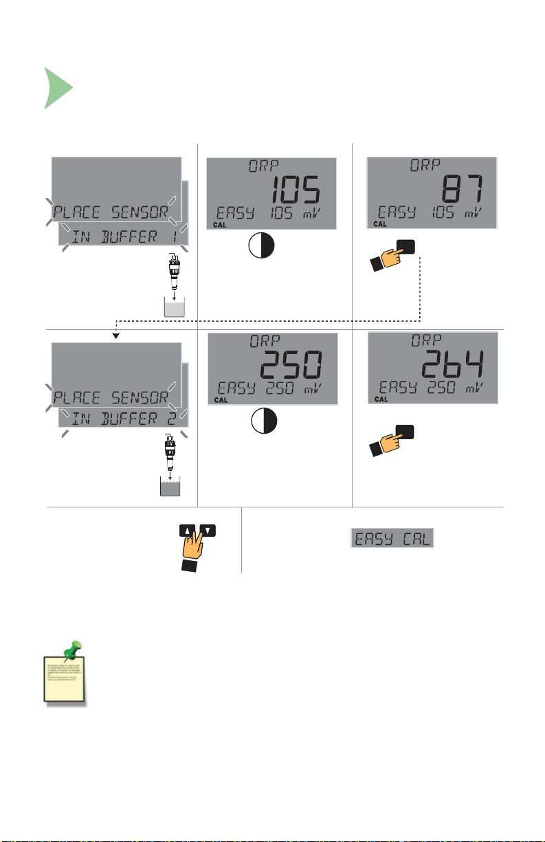
34. Calibration Procedures: ORP
EasyCal Procedure - ORP
EasyCal is the fastest and simplest periodic calibration method.
Requires a prepared quinhydrone solution:
Saturate 50 mL of pH 4 and 7 buffers with 1/8 g quinhydrone.
To Calibrate: To Accept:Response:
Place electrode tip in
saturated pH 7.0 buffer.
pH 7.0 = 87 mV
Allow for stabilization
1
30s
30 seconds
30s
Place electrode tip in
saturated pH 4.0 buffer.
pH 4.0 = 264 mV
Allow for stabilization
30 seconds
ENTER
to accept
to accept second
ENTER
buffer calibration
2
To exit menus and return to
9,(:SUHVVŸDQGź
buttons at the same time.
+
Display returns to VIEW
Mode in 10 minutes
NOTE:
ORP solutions made with quinhydrone are very unstable and may not read
properly once exposed to air for a prolonged time.
These solutions must be disposed of within an hour.
The solution can be used for calibrating more than one sensor.
However, the solution must remain free of debris and must not be diluted by
rinse water from previous calibrations.
Acceptable ranges for the readings are ± 80 mV (i.e., 87 ± 80 mV).
OMEGA DPU91 Transmitter58
Page 59
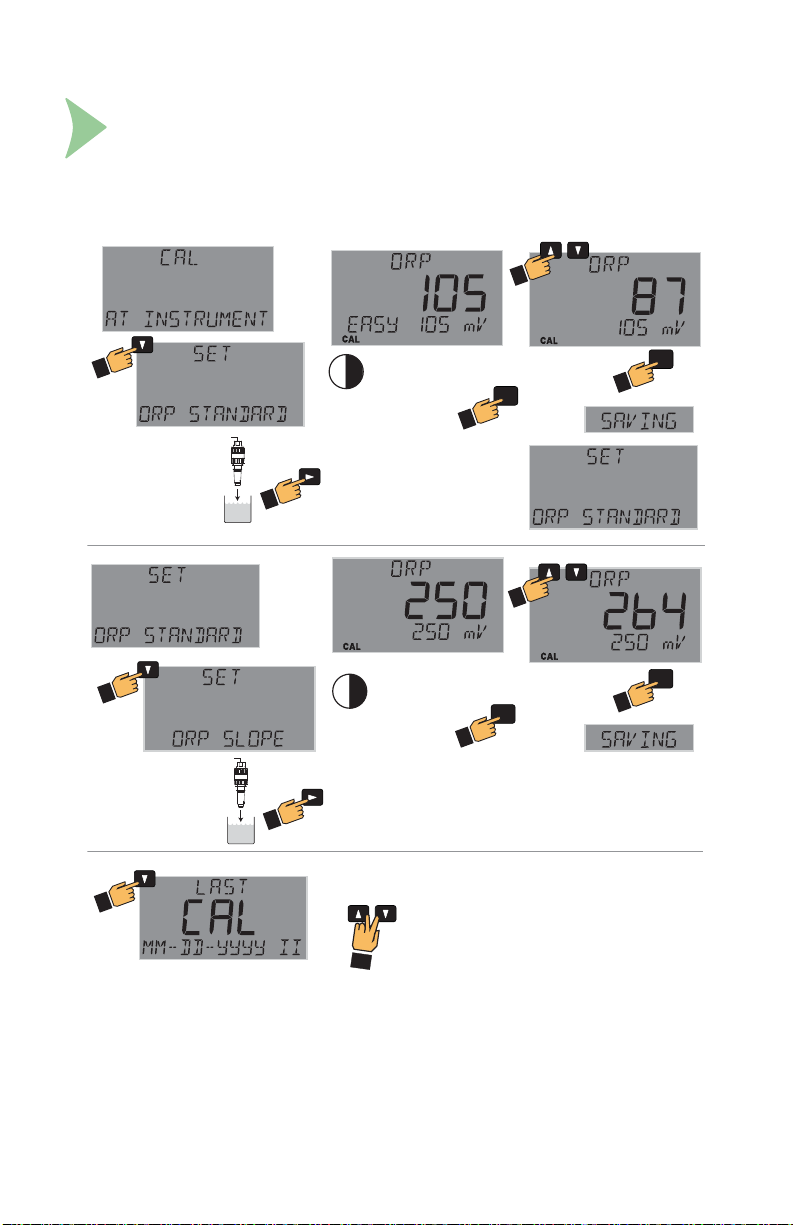
34. Calibration Procedures: ORP - continued
Manual Calibration Procedure - ORP
Requires prepared buffers and a prepared quinhydrone solution:
Saturate 50 mL of pH 4 and 7 buffers with 1/8 g quinhydrone.
(System calibration is possible with two known ORP solutions, but use a
buffer close to your own process value).
To Calibrate: To Change Reading:
Place electrode tip in
saturated pH 7.0 buffer.
pH 7.0 = 87 mV
To Set Slope:
Place electrode tip in
saturated pH buffer two
pH units different than
standard.
pH 4.0 = 264 mV
To Set Calibration Date:
30s
Allow for stabilization
30 seconds to
several minutes
30s
Allow for stabilization
30 seconds to
several minutes
+
Display returns to
VIEW Mode
ENTER
to accept
ENTER
to accept
to accept
To Change Reading:
to accept
ENTER
ENTER
Single-point calibration sets STANDARD only;
Omega recommends a two-point calibration to set SLOPE in addition to STANDARD.
Quick Manual Calibration Procedures:
1-Point Calibration:
1. Set solution standard.
2-Point Calibration (recommended):
1. Set solution standard.
2. Set solution slope.
59OMEGA DPU91 Transmitter
Page 60

35. Calibration Procedures: Conductivity/Resistivity
Calibration Procedure - Conductivity/Resistivity
AutoCal is the fastest and simplest periodic calibration method.
Requires prepared buffer of a value appropriate to your process.
AutoCal Procedure
AutoCal is a single-point calibration system. During this procedure, if the measured
value is within ± 10% of any of the test values listed below, the DPU91 will automatically
recognize the test value and calibrate the output to that value.
NOTE: The fi rst step (Reset) is recommended each time an electrode is replaced, but is
NOT necessary upon initial installation or periodic calibration.
NOTE: Ensure that the buffer solution is within ± 5 °C of 25 °C.
1. Reset the sensor to factory calibration (refer to sensor manual for procedure).
2. On the DPU91, select AUTO CAL from the CAL menu. Press .
3. Place the electrode/sensor assembly into the conductivity test solution appropriate
to your operating range. Shake the electrode to dislodge any air bubbles visible on
the surface of the electrode.
4. Allow at least 2 minutes for the electrode response to stabilize.
5. When the display stabilizes, press ENTER.
6. If calibration is successful, the DPU91 will display "SAVING". If error is too large,
"OUT OF RANGE USE MANUAL CALIBRATION" will display.
Calibration is complete. Return the system to service.
Conductivity units are displayed as selected in the CALIBRATE menu.
Resistivity displayed when K or M ranges are selected.
Manual Cal Procedure
NOTE: The fi rst step (Reset) is recommended each time an electrode is replaced,
but is NOT necessary upon initial installation or periodic calibration.
NOTE: Ensure that the buffer solution is within ± 5 °C of 25 °C.
1. Reset the sensor to factory calibration (refer to sensor manual for procedure).
2. On the DPU91, select MANUAL CAL from the CAL menu. Press .
3. Place the electrode/sensor assembly into the
conductivity test solution appropriate to your
operating range. Shake the electrode to dislodge
any air bubbles visible on the surface of the electrode.
4. Allow at least 2 minutes for the electrode response
to stabilize.
5. When the display stabilizes, enter the value of the
buffer solution using the , and buttons.
6. Press ENTER.
7. DPU91 will display "SAVING". If error is too large,
"ERR TOO LARGE TO CALIBRATE" will display.
Calibration is complete. Return the system to service.
OMEGA DPU91 Transmitter60
Available buffer values:
10
100
146.93
200
500
1000
1408.8
5000
10,000
12856
50,000
100,000
(all values in S)
Page 61
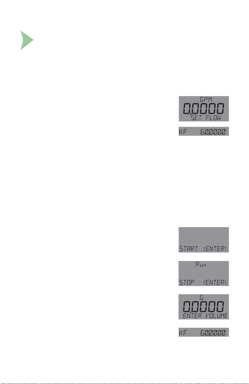
36. Calibration Procedures: Flow
Calibration Procedure - Flow
Select RATE CALIBRATION to match the dynamic fl ow rate to an external
reference. Entering a rate will modify the existing K-Factor.
Select VOLUME CALIBRATION if the fl ow rate can be determined by fi lling
a vessel of known volume. The DPU91 will count the number of pulses
generated as the known volume of fl uid passes through the sensor, and then
use the information to calculate a new K-Factor.
Rate Calibration Procedure
1. Use , and to set the fl ow rate in the fl ashing display to
match the reference meter. Press ENTER when completed.
2. The DPU91 displays the newly calculated K-Factor for
your reference.
If the calculated K-Factor is less than 0.0001 or
greater than 999999 (out of range at either extreme),
the DPU91 displays "ERROR NEW KF OUT OF RANGE"
and returns to RATE CAL.
If fl ow is too low to accurately calibrate, the DPU91 displays
"ERROR FLOW RATE TOO LOW and returns to RATE CAL.
3. Press ENTER to accept the new K-Factor (DPU91 displays
"SAVING") or press + keys simultaneously to escape without
saving and return to Enter Volume.
NOTE:
You may enter your own calculated K-Factor in the INPUT menu.
Volume Calibration Procedure
1. Press ENTER to start the volumetric calibration period.
The DPU91 starts counting pulses from the fl ow sensor.
2. Press ENTER to stop the volumetric calibration period.
The DPU91 stops counting pulses from the fl ow sensor.
3. Enter the volume of fl uid known to have fl owed past the
sensor during the volumetric calibration period.
This will modify the existing Flow K-Factor.
4. The DPU91 displays the newly calculated K-Factor for your
reference.
If the calculated K-Factor is less than 0.0001 or
greater than 999999 (out of range at either extreme),
the DPU91 displays "ERROR VOLUME TOO HIGH"
(or LOW) and returns to VOLUME CAL.
5. Press ENTER to accept the new K-Factor (DPU91 displays
"SAVING") or press + keys simultaneously to escape
without saving and return to Enter Volume.
NOTE:
You may enter your own calculated K-Factor in the INPUT menu.
61OMEGA DPU91 Transmitter
Page 62

37. Calibration Error Messages
Message Cause Solution
(Cond/Res) Error > 10% in AutoCal Use manual calibration method
Out Of Range Use
Manual Calibration
Err Too Large To
Calibrate
Error Volume
Too Low
Error New KF
Out Of Range
Error Flow Rate
Too Low
Cal Error Out
Of Range
Slope Too Close
To Standard
Standard Too
Close To Slope
Level Offset
Too Large
Pressure Too High
Pressure
Too Close To Zero
(pH) Buffer not found;
Error > ±1.5 pH units
(ORP) No quinhydrone in buffer
Error greater than ±80 mV
(Cond/Res) Manual cal when
error > 100%
(pH) Offset > 1.3 pH units;
Slope error > 100%
(Press) Slope must be < ±50%
or offset must be < 2.75 PSI or
equivalent.
(Sal) Slope error > 1000%
User-entered volume too small
to calibrate
The calculated K-Factor
too low or high
(Rate Cal) Flow too low to
accurately calibrate
(4 to 20 mA) Slope error > 1000%
(Temp) Offset must be < ±20 °C or
equivalent.
(4 to 20 mA) Difference in calibration
values must be > 0.1 units
(pH) Difference in calibration values
must be > 2 pH units
(ORP) Difference in calibration
values must be > 30 mV
(4 to 20 mA) Difference in calibration
values must be > 0.1 units
(pH) Difference in calibration values
must be > 2 pH units
(ORP) Difference in calibration
values must be > 30 mV
Offset must be < 1.0 meter
Pressure must be lower than 2.5 PSI
or equivalent to do zero cal.
Pressure must be higher than 3 PSI
or equivalent to do slope calibration.
Use 4, 7, 10 pH buffers (with
quinhydrone for ORP calibration)
Clean sensor and retry EasyCal
Use manual calibration method
Inspect sensor and wiring for
damage
Clean sensor
Check reference
Clean sensor
Replace sensor
Correct volume entry
Use longer calibration period
Verify volume or rate entered
Verify fl ow is present
Increase fl ow
Check input at 4 mA and 20 mA
settings
Check sensor range
Check reference
Replace sensor
Check sensor
Use fresh buffer
Use two different buffer values
Clean sensor
Clean sensor
Use fresh 4, 7, 10 pH buffers
Use two different buffer values
Decrease offset
Replace sensor
Decrease pressure
Increase pressure
Check reference
OMEGA DPU91 Transmitter62
Page 63

38. USP Limits
USP (United States Pharmacopoeia) has defi ned a set of
conductivity values (limits) to be used for pharmaceutical water.
The standard requires that conductivity measurement without
temperature compensation be used for these applications.
The limits vary according to the temperature of the sample.
The DPU91 has the USP limits stored in memory.
It will automatically determine the proper USP limit based
on the measured temperature.
Using the USP function
USP setpoints are defi ned as a percentage below the USP limit,
so a USP alarm is always a HIGH alarm.
The DPU91 can be set to warn you if the conductivity
approaches within a set percentage of the USP limit.
The following settings and conditions are required for a USP
relay function:
1. In the RELAY menu:
• RELAY MODE must be set to USP.
2. In the INPUT menu:
• COND UNITS must be set to μS.
• TEMP COMP must be set to None.
Example:
• The water temperature is 19 ºC, so the USP limit is 1.0 S.
• The USP PERCNT is set to 40%.
• The relay will be activated when the conductivity value
reaches 40% below the 1.0 USP limit, or 0.6 S.
• If the water temperature drifts to more than 20 ºC,
the DPU91 will automatically adjust the USP limit to 1.1.
The relay will now be activated when the conductivity
value reaches 40% below 1.1 S (0.66 S).
Temperature
Range (ºC)
0 to < 5 0.6
5 to < 10 0.8
10 to < 15 0.9
15 to < 20 1.0
20 to < 25 1.1
25 to < 30 1.3
30 to < 35 1.4
35 to < 40 1.5
40 to < 45 1.7
45 to < 50 1.8
50 to < 55 1.9
55 to < 60 2.1
60 to < 65 2.2
65 to < 70 2.4
70 to < 75 2.5
75 to < 80 2.7
80 to < 85 2.7
85 to < 90 2.7
90 to < 95 2.7
95 to < 100 2.9
100 to < 105 3.1
USP limit
(μS)
39. Maintenance
Clean the instrument case and front panel with a soft cotton cloth dampened with a
mild liquid soap solution.
Never wipe the front window with static retentive cloths such as wool or polyester
which may induce a static charge. If a static charge develops on the window,
you may notice temporary blotches form on the screen.
When this occurs, clean the front window with an anti-static cloth, or a soft cotton
cloth and anti-static spray or a mild liquid soap solution to remove the static charge.
63OMEGA DPU91 Transmitter
Page 64

40. Specifi cations
General
Input channels ..............One
Enclosure and Display
Case Material ...............PBT
Window .........................Shatter-resistant glass
Keypad .........................4 buttons, injection-molded silicone rubber seal
Display ..........................Backlit, 7- and 14-segment
Indicators ......................“Dial-type” digital bar graph
Update rate ...................1 s
LCD Contrast ................5 settings
Enclosure
Size .......................¼ DIN
Color .....................Black (Panel Mount),
Mounting
Panel ....................¼ DIN, ribbed on four sides for panel mounting clip inside panel,
Field ......................Mounts to standard Omega fi eld mount junction boxes.
Wall .......................Large enclosure (sold as an accessory) that encases the panel
Terminal Blocks
Pluggable screw type
Torque ratings
Cond/Res, Open Collector,
Power/Loop ...........0.33 Nm (3.0 lb-in.)
Freq/S3L ...............0.24 Nm (2.2 lb-in.)
Relay .....................0.49 Nm (4.4 lb-in.)
Connector wire gauge
Power, Loop ..........12 to 28 AWG
Open Collector ......12 to 28 AWG
Freq/S3L ...............16 to 28 AWG
Module connector wire gauge
Relay .....................12 to 28 AWG
Cond/Res ..............16 to 28 AWG
Batch .....................up to 14 AWG
Environmental Requirements
Ambient operating temperature:
Backlit LCD...................... -10 °C to 70 °C (14 °F to 158 °F)
Storage Temp .................. -15 °C to 70 °C (5 °F to 158 °F)
Relative Humidity ............ 0 to 100% condensing for Field and Panel Mount (front only);
Maximum Altitude ............ 4,000 m (13,123 ft); use only DC power supply to maintain
Enclosure Rating ............. Designed to meet NEMA 4X/IP65 (front face only on panel
Installation Category Cat II
Pollution Degree 2
Yellow and black (Integral Mount)
silicon gasket included
Optional angle adjustment adapter is available
mount transmitter
: use minimum 105 °C rated wire
0 to 95% non-condensing for Panel Mount back side.
UL safety standard up to this altitude
mount; fi eld mount is 100% NEMA 4X/IP65).
OMEGA DPU91 Transmitter64
Page 65

40. Specifi cations - continued
Performance Specifi cations
System Accuracy
Primarily dependent upon the sensor.
System Response
Primarily dependent upon the sensor.
Controller adds a maximum of 150 ms processing delay to the sensor electronics.
Minimum update period is 100 ms
System response is tempered by the display rate,
output averaging and sensitivity feature.
Electrical Requirements
Power to Sensors
Voltage................................. +4.9 to 5.5 VDC @ 25 °C, regulated
Current................................. 1.5 mA max in loop power mode;
20 mA max when using DC power
Short Circuit ......................... Protected
Isolation ...............................
No isolation when using loop power only
Input Power Requirements
DC (preferred) ..................... 24 VDC; input range: 10.8 to 35.2 VDC regulated
DPU91 w/o Relay Module ... 200 mA *
DPU91 w/ Relay Module ..... 300 mA *
*The current draw of the other modules and the sensors are minimal
Loop..................................... 10.8 to 35.2 VDC 4 to 20 mA (30 mA max.)
Overvoltage protection ........ 48 Volt Transient Protection Device (for DC ONLY)
Current limiting for circuit protection
Reverse-Voltage protection
Loop Characteristics
DC Powered System (preferred)
Max. loop impedance:
@ 12 V loop power .................. 250 max.
@ 18 V loop power .................. 500 max.
@ 24 V loop power .................. 750 max.
Loop Powered System
Max. loop impedance:
@ 12 V loop power .................. 50 max.
@ 18 V loop power .................. 325 max.
@ 24 V loop power .................. 600 max.
Low voltage (< 48 V AC/DC) to loop with DC power connected
65OMEGA DPU91 Transmitter
Page 66

40. Specifi cations - continued
Relay Specifi cations
Hysteresis ....................................Adjustable (absolute in Engineering Units)
Latch ............................................Reset in test screen only
On Delay......................................9999.9 seconds (max)
Cycle Delay .................................99999 seconds (max)
Test Mode ....................................Set On or Off
Maximum Pulse Rate ..................300 pulses/minute
Proportional Pulse ....................... 400 pulses/minute
Volumetric Pulse Width................0.1 to 3200 s
PWM period .................................0.1 to 320 s
Open Collector
Type .............................................NPN
Max. Voltage Rating .................... 30 VDC
Max. Current Rating ....................50 mA
Dry-Contact Relays
Type .............................................SPDT
Form ............................................ C
Max. Voltage Rating .................... 30 VDC or 250 VAC
Max. Current Rating ....................5 A resistive
Shipping Weights
Base Unit ................................. 0.63 kg (1.38 lb)
DPU90-COMM Module............ 0.16 kg (0.35 lb)
Conductivity Module ................ 0.16 kg (0.35 lb)
Relay Module........................... 0.19 kg (0.41 lb)
Batch Module........................... 0.16 kg (0.35 lb)
Input Types
Digital (S
Open collector
pH/ORP input via the Digital (S
Raw Conductivity/Resistivity input directly from Omega Conductivity/Resistivity
electrodes via DPU90-C Direct Conductivity/Resistivity Module or via the Digital (S
output from the CDTX-2850 Conductivity/Resistivity Sensor Electronics
Sensor Types:
Flow, pH/ORP, Conductivity/Resistivity, Salinity
Input Specifi cations
Digital (S
Frequency Type Sensors:
Sensitivity......................... (for coil type sensors):
Freq. Range ..................... (for square wave type sensors):
Accuracy .......................... ± 0.5% of reading max error @ 25 °C
Range .............................. 0.5 to 1500 Hz
Resolution ........................ 1 s
Repeatability .................... ± 0.2% of reading
Power Supply
Rejection .......................... No Effect ± 1 A per volt
Short Circuit ..................... Protected
Reverse Polarity .............. Protected (no isolation when using loop power only)
Update Rate (1/frequency) + 150 ms
3
L) or AC frequency
3
L) output from the PHEH pH/ORP Sensor Electronics
3
L) .......................... Serial ASCII, TTL level, 9600 bps
80 mV @ 5 Hz, gradually increasing with frequency to 2.5 V
0.5 Hz to 1500 Hz @ TTL level input or open collector
3
L)
OMEGA DPU91 Transmitter66
Page 67

40. Specifi cations - continued
Display Ranges:
pH: .................................... 0.00 to 15.00 pH
pH Temp.: ......................... -99 °C to 350 °C (-146 °F to 662 °F)
ORP: ................................ -1999 to 1999.9 mV
Flow Rate: ........................ -9999 to 99999 units per second, minute, hour or day
Totalizer: ........................... 0.00 to 99999999 units
Conductivity: ..................... 0.0000 to 99999 S, mS, PPM and PPB (TDS), k, M
Cond. Temp.: .................... -99 °C to 350 °C (-146 °F to 662 °F)
Temperature: .................... -99 °C to 350 °C (-146 °F to 662 °F)
Pressure: .......................... -40 to 1000 psi
Level: ................................ -9999 to 99999 m, cm, ft, in, %
Volume: ............................ 0 to 99999 cm
Salinity .............................. 0 to 100 PPT
Dissolved O
..................... 0 to 20 mg/L, 0 to 200%
2
Output Specifi cations
Current Loop Out ................. ANSI-ISA 50.00.01 Class H
Span .................................... 3.8 to 21 mA
Zero ..................................... 4.0 mA factory set; user programmable from 3.8 to 4.2 mA
Full Scale .............................
20.00 mA factory set; user programmable from 19.0 to 21.0 mA
Accuracy .............................. ± 32 A max. error @ 25 °C @ 24 VDC
Resolution............................ 6 A or better
Temp. Drift ........................... ± 1 A per °C
Pwr Sply Rejection .............. ± 1 A per V
Isolation ............................... Low voltage (< 48 VAC/DC)
Voltage................................. 10.8 to 35.2 VDC
Max. Impedance: ................. 250 @ 12 VDC
500 @ 18 VDC
750 @ 24 VDC
Update Rate ........................ 100 mS nominal
Short circuit and reverse polarity protected
Adjustable span, reversible
Error Condition .................... Selectable error condition 3.6 or 22 mA.
Actual update rate determined by sensor type
Test Mode: ........................... Increment to desired current (range 3.8 to 21.00 mA)
Open Collector Outputs: ...... 1
Analog Outputs: ................... 1 passive
Current Outputs
One 4 to 20 mA output
Linear scaling
Logarithmic scaling for Conductivity
Reverse span
Selectable error mode: 3.6 mA or 22 mA
Test Output mode that allows the user to test the current output
Adjustable 4 to 20 mA end points
HART communication via optional DPU90-COMM Module
3
, m3, in3, ft3, gal, L, lb, kg, %
67OMEGA DPU91 Transmitter
Page 68

OMEGA DPU91 Transmitter68
Page 69

69OMEGA DPU91 Transmitter
Page 70

41. Ordering Information
DPU91 Transmitter Base Unit:
Single Channel, Multi-Parameter, 4 to 20 mA, Open Collector, DC Power
Mfr. Part No Description
DPU91P DPU91 Base Unit, Panel Mount
DPU91 DPU91 Base Unit, Field Mount
DPU91-BC Batch Controller System
Optional Modules
DPU90-R Relay Module - 2 DCR (Dry Contact Relays)
DPU90-C Direct Conductivity/Resistivity Module
DPU90-COMM COMM Module
DPU90-BCM Batch Module
Accessories
DPU90-CT PC COMM Confi guration/Diagnostic tool
FP90UM Universal Mount Kit
FP90RC RC Filter Kit (for relay use), 2 per kit
FP90IM Flow Sensor Integral Mounting Kit, NPT, Valox
FP90IM34 ¾ in. Integral Mount Kit
DPU90-WM Wall Mount Accessory for DPU91
FPM-5000-LTCK Liquid Tight Connector Kit, NPT (1 pc.)
DPU90-AK Angle Adjustment Adapter Kit (for Field Mounting)
OMEGA DPU91 Transmitter70
Page 71

WARRANTY/DISCLAIMER
OMEGA ENGINEERING, INC. warrants this unit to be free of defects in materials and workmanship for a
period of 13 months from date of purchase. OMEGA’s WARRANTY adds an additional one (1) month
grace period to the normal one (1) year product warranty to cover handling and shipping time. This
ensures that OMEGA’s customers receive maximum coverage on each product.
If the unit malfunctions, it must be returned to the factory for evaluation. OMEGA’s Customer Service
Department will issue an Authorized Return (AR) number immediately upon phone or written request.
Upon examination by OMEGA, if the unit is found to be defective, it will be repaired or replaced at no
charge. OMEGA’s WARRANTY does not apply to defects resulting from any action of the purchaser,
including but not limited to mishandling, improper interfacing, operation outside of design limits,
improper repair, or unauthorized modification. This WARRANTY is VOID if the unit shows evidence of
having been tampered with or shows evidence of having been damaged as a result of excessive corrosion;
or current, heat, moisture or vibration; improper specification; misapplication; misuse or other operating
conditions outside of OMEGA’s control. Components in which wear is not warranted, include but are not
limited to contact points, fuses, and triacs.
OMEGA is pleased to offer suggestions on the use of its various products. However,
OMEGA neither assumes responsibility for any omissions or errors nor assumes liability for
any damages that result from the use of its products in accordance with information provided
by OMEGA, either verbal or written. OMEGA warrants only that the parts manufactured by the
company will be as specified and free of defects. OMEGA MAKES NO OTHER WARRANTIES OR
REPRESENTATIONS OF ANY KIND WHATSOEVER, EXPRESSED OR IMPLIED, EXCEPT THAT OF
TITLE, AND ALL IMPLIED WARRANTIES INCLUDING ANY WARRANTY OF MERCHANTABILITY
AND FITNESS FOR A PARTICULAR PURPOSE ARE HEREBY DISCLAIMED. LIMITATION OF
LIABILITY: The remedies of purchaser set forth herein are exclusive, and the total liability of
OMEGA with respect to this order, whether based on contract, warranty, negligence,
indemnification, strict liability or otherwise, shall not exceed the purchase price of the
component upon which liability is based. In no event shall OMEGA be liable for
consequential, incidental or special damages.
CONDITIONS: Equipment sold by OMEGA is not intended to be used, nor shall it be used: (1) as a “Basic
Component” under 10 CFR 21 (NRC), used in or with any nuclear installation or activity; or (2) in medical
applications or used on humans. Should any Product(s) be used in or with any nuclear installation or
activity, medical application, used on humans, or misused in any way, OMEGA assumes no responsibility
as set forth in our basic WARRANTY/ DISCLAIMER language, and, additionally, purchaser will indemnify
OMEGA and hold OMEGA harmless from any liability or damage whatsoever arising out of the use of the
Product(s) in such a manner.
Direct all warranty and repair requests/inquiries to the OMEGA Customer Service Department.
RETURN REQUESTS/INQUIRIES
BEFORE RETURNING ANY PRODUCT(S) TO OMEGA, PURCHASER MUST OBTAIN AN AUTHORIZED
RETURN (AR) NUMBER FROM OMEGA’S CUSTOMER SERVICE DEPARTMENT (IN ORDER TO AVOID
PROCESSING DELAYS). The assigned AR number should then be marked on the outside of the return
package and on any correspondence.
The purchaser is responsible for shipping charges, freight, insurance and proper packaging to prevent
breakage in transit.
FOR WARRANTY RETURNS, please have the
following information available BEFORE contacting
OMEGA:
1. Purchase Order number under which the product
was PURCHASED,
2. Model and serial number of the product under
warranty, and
Repair instructions and/or specific problems
3.
relative to the product.
OMEGA’s policy is to make running changes, not model changes, whenever an improvement is possible. This affords
our customers the latest in technology and engineering.
OMEGA is a trademark of OMEGA ENGINEERING, INC.
© Copyright 2018 OMEGA ENGINEERING, INC. All rights reserved. This document may not be copied,
photocopied, reproduced, translated, or reduced to any electronic medium or machine-readable form, in whole or in
part, without the prior written consent of OMEGA ENGINEERING, INC.
FOR NON-WARRANTY REPAIRS,
OMEGA for current repair charges. Have
the following information available BEFORE
contacting OMEGA:
1. Purchase Order number to cover the COST
of the repair,
2. Model and serial number of the product, and
3. Repair instructions and/or specific problems
relative to the product.
consult
Page 72

Where Do I Find E
verything I Need for
Process Measurement and Control?
OMEGA…Of Course!
Shop online at omega.com
TEMPERATURE
Thermocouple, RTD & Thermistor Probes, Connectors, Panels & Assemblies
Wire: Thermocouple, RTD & Thermistor
Calibrators & Ice Point References
Recorders, Controllers & Process Monitors
Infrared Pyrometers
PRESSURE, STRAIN AND FORCE
Transducers & Strain Gages
Load Cells & Pressure Gages
Displacement Transducers
Instrumentation & Accessories
FLOW/LEVEL
Rotameters, Gas Mass Flowmeters & Flow Computers
Air Velocity Indicators
Turbine/Paddlewheel Systems
Totalizers & Batch Controllers
pH/CONDUCTIVITY
pH Electrodes, Testers & Accessories
Benchtop/Laboratory Meters
Controllers, Calibrators, Simulators & Pumps
Industrial pH & Conductivity Equipment
DATA ACQUISITION
Communications-Based Acquisition Systems
Data Logging Systems
Wireless Sensors, Transmitters, & Receivers
Signal Conditioners
Data Acquisition Software
HEATERS
Heating Cable
Cartridge & Strip Heaters
Immersion & Band Heaters
Flexible Heaters
Laboratory Heaters
ENVIRONMENTAL
MONITORING AND CONTROL
Metering & Control Instrumentation
Refractometers
Pumps & Tubing
Air, Soil & Water Monitors
Industrial Water & Wastewater Treatment
pH, Conductivity & Dissolved Oxygen Instruments
M5323/0518
 Loading...