

Page 1
User’s Guide
Shop online at
omega.com
e-mail: [email protected]
For latest product manuals:
www.omegamanual.info
SM
DPU90-CT
PC COMM / Sensor Confi guration Tool
Page 2

omega.com [email protected]
Servicing North America:
U.S.A. Omega Engineering, Inc.
Headquarters: Toll-Free: 1-800-826-6342 (USA & Canada only)
Customer Service: 1-800-622-2378 (USA & Canada only)
Engineering Service: 1-800-872-9436 (USA & Canada only)
Tel: (203) 359-1660 Fax: (203) 359-7700
e-mail: [email protected]
For Other Locations Visit omega.com/worldwide
The information contained in this document is believed to be correct, but OMEGA accepts no liability for any errors it contains, and reserves
the right to alter specifications without notice.
Page 3
Contents
1. Description ......................................................... 3 10. FMG-550 Magmeter Wiring ...............................6
2. Safety Information ..............................................3 11. DPU91 Wiring ....................................................6
3. Specifi cations ..................................................... 3 12. General Software Operation ..............................7
4. Required Equipment ..........................................4 13. PHTX-275 & PHEH-275 Operation ....................7
5. Application Specifi c Information ......................... 4 14. FMG-3000 & FMG-550 Operation ..................8-9
6. Install Software ..................................................4 15. DPU91 Operation ........................................ 10-11
7. Run Software .....................................................4 16. Datalogger Operation .......................................12
8. PHTX-275 & PHEH-275 Wiring .........................5 17. Notes ................................................................13
9. FMG-3000 Magmeter Wiring .............................5 18. Ordering Information ........................................14
1. Description
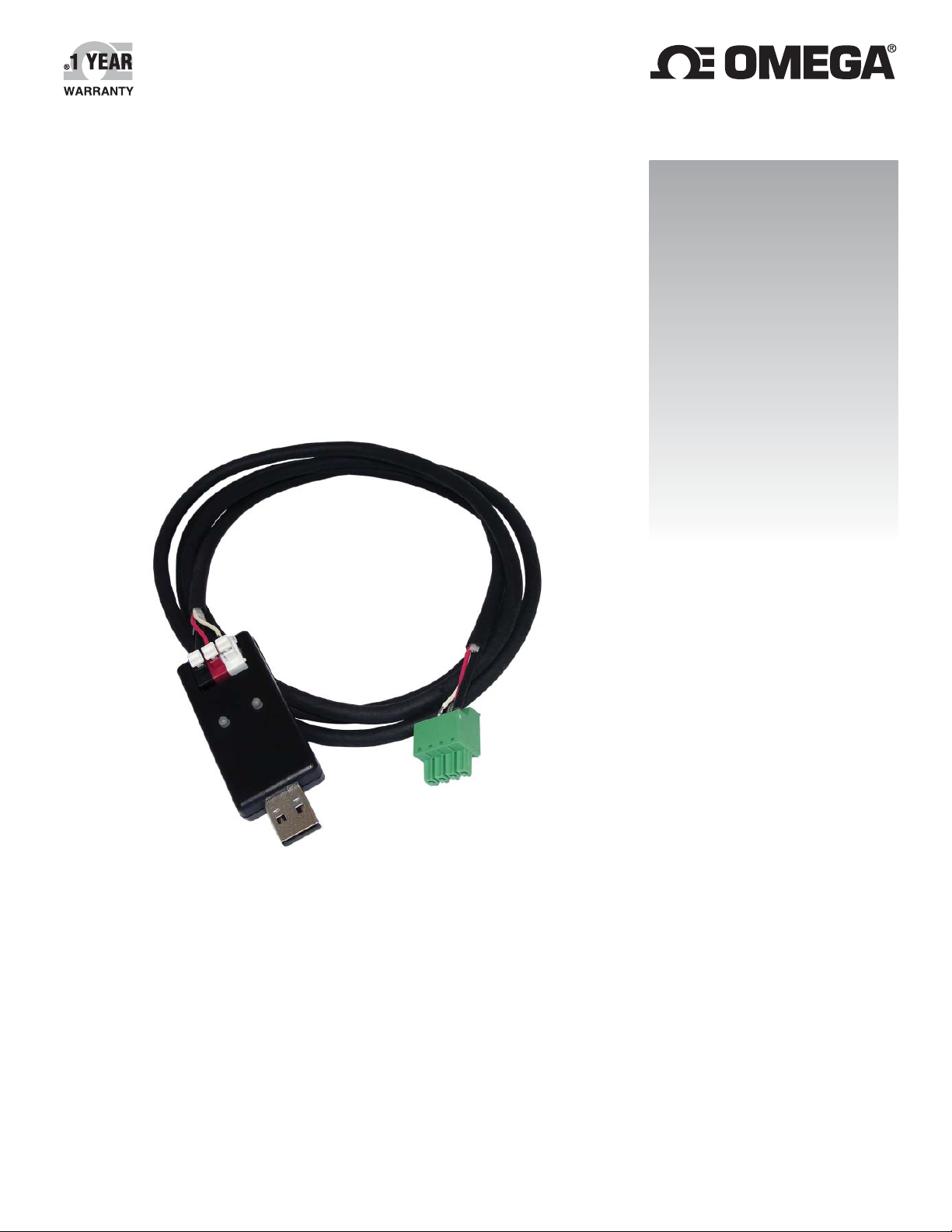
The DPU90-CT PC COMM / Sensor Confi guration Tool is a USB to Digital convertor and Microsoft® Windows®
compatible software program used for interfacing with Omega DPU91 Transmitters and blind sensors via a computer.
The DPU90-CT tool and software allows:
• Set application parameters (Engineering units, 4 to 20 mA span, etc.)
• Save the setting confi guration data to a computer fi le.
• Upload a previously stored confi guration data fi le into the Omega product.
• Monitor the product's data and performance and log the data to a fi le.
• Reset the product settings to factory default condition.
Certain parameters (such as calibration) cannot be changed because access to an external sensor is required.
Microsoft, Windows, and Windows Vista are registered trademarks of Microsoft Corporation in the United States and other countries.
2. Safety Information
Warning / Caution / Danger
Indicates a potential hazard. Failure to follow all warnings may lead to equipment damage, injury, or death.
Electrostatic Discharge (ESD) / Electrocution Danger
Alerts user to risk of potential damage to product by ESD, and/or risk of potential of injury or death via electrocution.
NOTE / Technical Notes
Highlights additional information or detailed procedure.
3. Specifi cations
Compatibility
Omega Products.................. PHTX/PHEH-275,
FMG-3000, FMG-550, and
DPU91 Transmitter
Operating System ................ Windows XP, Windows Vista,
Windows 7 (32 and 64 bit),
Windows 8 and 8.1
General
Enclosure............................. ABS
Red Indicator ....................... POWER ON
Blue Indicator....................... DATA COMMUNICATION
Input connections ................ 3-terminal connectors,
max. 14 AWG
Electrical
Communication rate ............ Maximum 19.2 kbs
Input power .......................... Supplied by USB interface
Output power ....................... 5 VDC ± 5%
Power consumption ............. 5 V @ 15 mA
Maximum current source ..... 50 mA
Maximum cable ................... 300 m (1000 ft)
Environmental
Storage Temperature ........... -20 °C to 100 °C
(-4 °F to 212 °F)
Relative Humidity................. 0 to 90% non-condensing
Operating Temperature ........ -15 °C to 55 °C
(5 °F to 131 °F) (module only)
Shipping Weight ................ 0.220 kg (0.48 lb)
®
OMEGA DPU90-CT PC COMM / Sensor Confi guration Tool
3
Page 4
4. Required Equipment
• Follow instructions carefully to avoid personal injury.
• DPU90-CT Tool: one USB to Digital converter
• 1 m DPU91 programming cable with terminal plug
• USB to USB extention cable
• Software installation CD
• PC / laptop with free USB port
• 24 VDC Isolated power source (Required to program 4 to 20 mA sensors, FMG-3000 and FMG-550 only)
5. Application Specifi c Information
PHTX/PHEH-275:
• Engineering Units, 4 to 20 mA span
FMG-3000 & FMG-550:
• Engineering Units, K-Factor, Pipe ID, Timebase, Averaging, Sensitivity, Noise Rejection, Low Flow Cut-Off, 4 to 20 mA span
DPU91:
• Instrument Type: (Flow, pH, ORP, Cond/Resist, Salinity, Batch)
• Sensor type specifi c settings
6. Install Software
Caution
Managed systems and network systems may
have security measures enabled that block the
installation of this program.
See the network administrator or IT (Information
Technology) staff if the software cannot be installed.
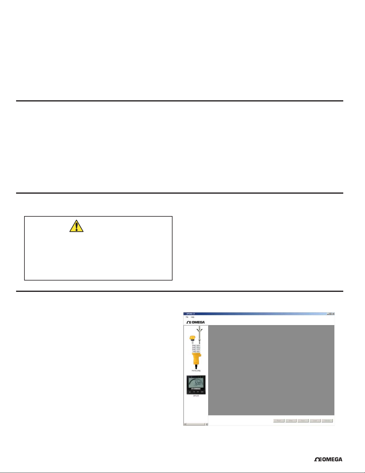
7. Run Software
1. On the PC, click Start and select Program Files.
2. Click on the Omega folder.
3. Click on the DPU90-CT folder.
4. Click on the DPU90-CT Tool icon.
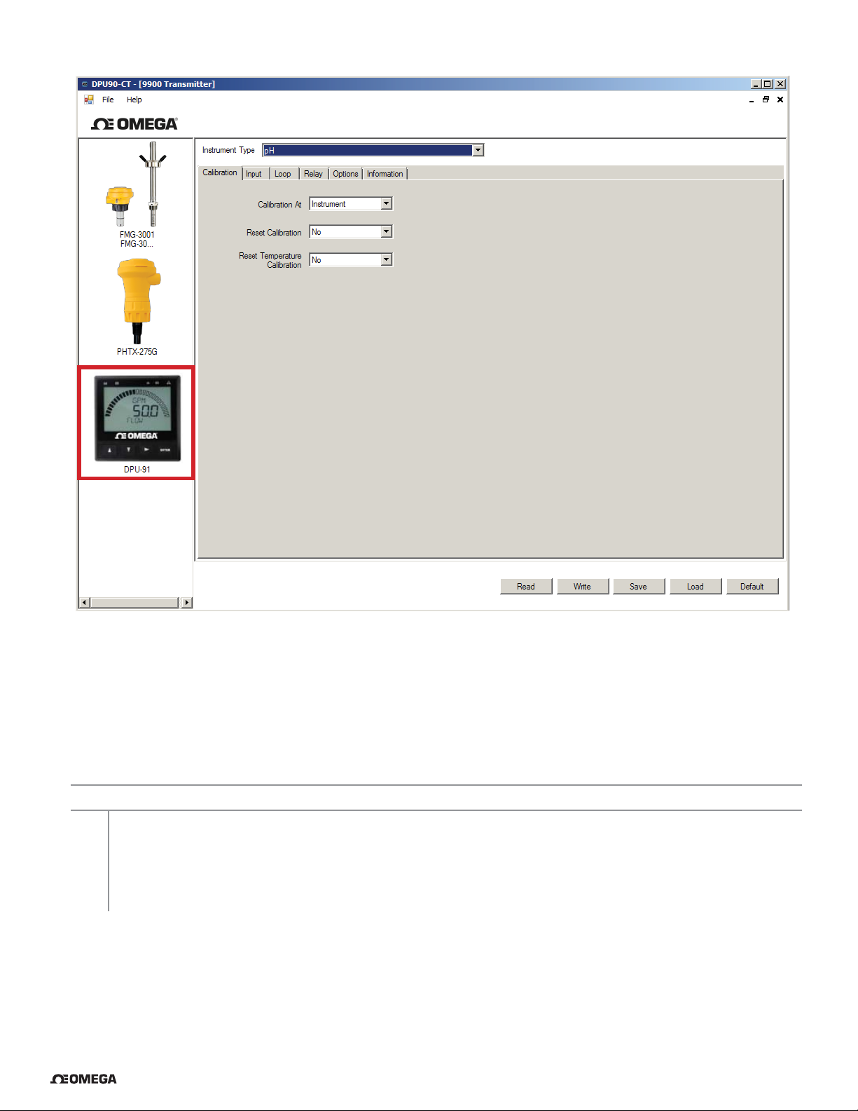
5. The DPU90-CT software screen shown here
should be on the computer display.
NOTE: Each time the DPU90-CT software is launched,
it automatically checks for and applies updates.
Software version is displayed by clicking on the Help
menu, then clicking on About.
1. Insert the CD ROM into the computer's CD/DVD drive.
• If Autorun is enabled on the computer, the
installation wizard will start.
• If Autorun is disabled on the computer, use Windows
Explorer to browse the contents of the CD and
double-click on the setup.exe fi le.
2. Follow the prompts in the installation wizard to
complete installing the software.
4 OMEGA DPU90-CT PC COMM / Sensor Confi guration Tool
®
Page 5
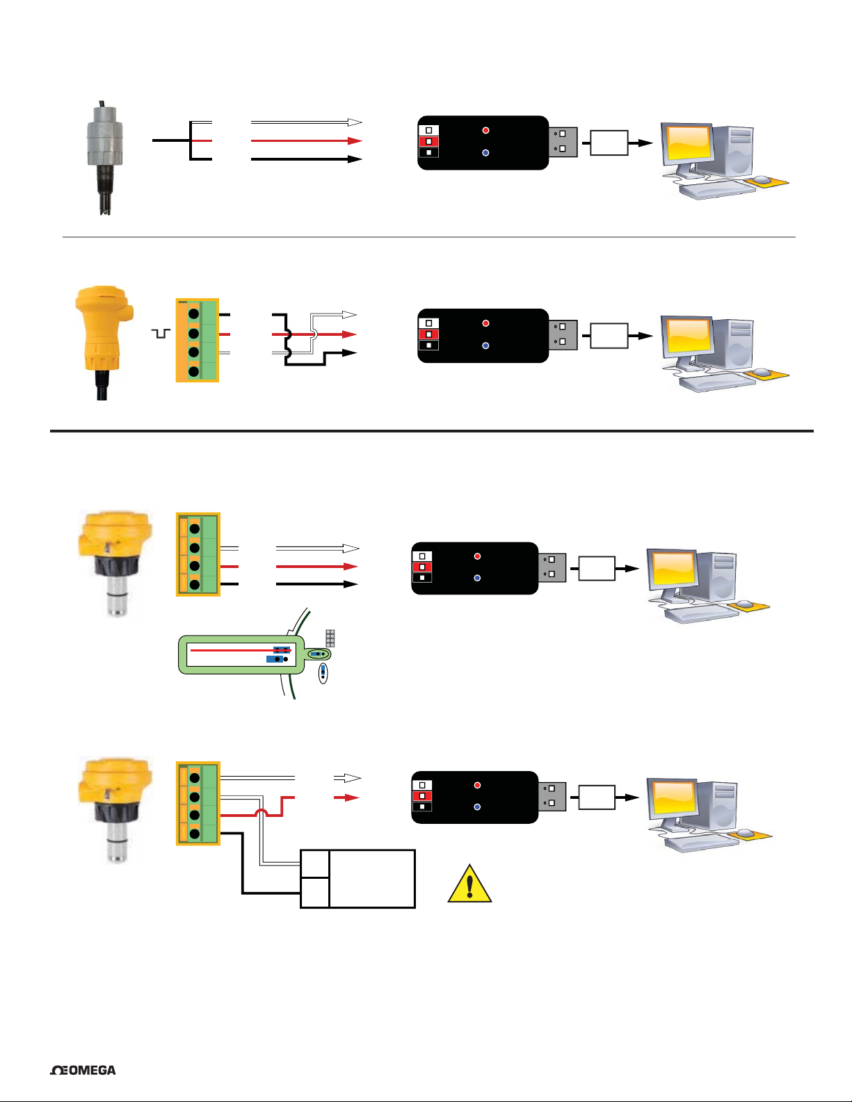
8. PHTX-275 & PHEH-275 Wiring
Omega PHTX/PHEH-275 Submersible pH Sensor
White
Red
Black
GND
Data
+5V out
Omega PHTX/PHEH-275 In-Line pH/ORP Sensor
+
-
S
4
Black
3
Red
2
White
1
GND
Data
+5V out
9. FMG-3000 Magmeter Wiring
Frequency or Digital Output
4
3
White
2
Red
1
Black
GND
Data
+5V out
USB
Windows PC
USB
Windows PC
USB
4 to 20 mA Output
FREQUENCY OUT
DIGITAL OUT
4
3
2
1
White
Red
-
+
JP2
Frequency / Digital jumper
must be in Digital Out position
GND
Data
+5V out
Isolated
24 VDC
Windows PC
USB
Windows PC
CAUTION!
Do not connect power directly to this device.
Turn 24 VDC Power OFF when wiring the magmeter.
®
OMEGA DPU90-CT PC COMM / Sensor Confi guration Tool
5
Page 6
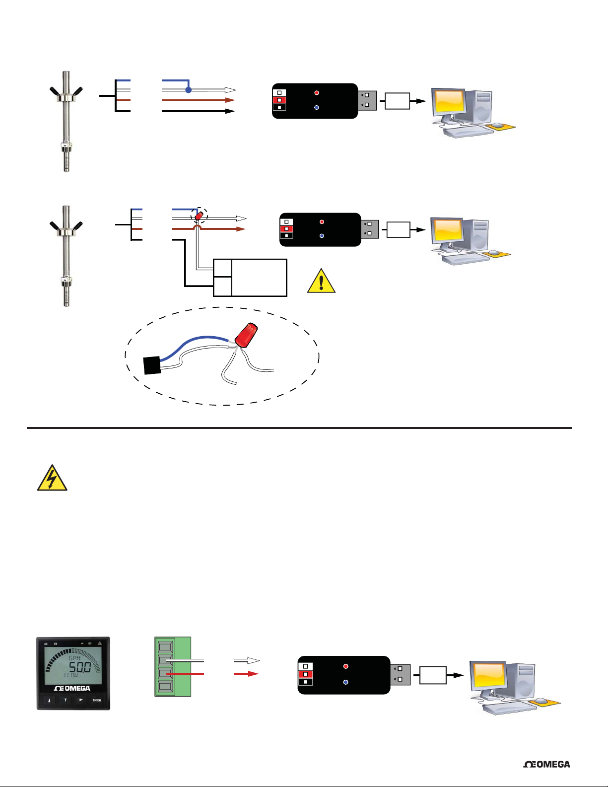
10. FMG-550 Magmeter Wiring
Frequency or Digital Output
4 to 20 mA Output
Blue
White
Brown
Black
White
Brown
Black
Blue
*Wire 1
Blue
White
*Wire 3
*Wire 2
*Wire 2
-
+
GND
Data
+5V out
GND
Data
+5V out
Isolated
24 VDC
*Wire 3
To -VDC
Wire Nut
To GND
USB
Windows PC
USB
CAUTION!
Do not connect power directly to this device.
Turn 24 VDC Power OFF when wiring the magmeter.
*Additional wire required
Windows PC
11. DPU91 W iring
Disconnect power on the DPU91 prior to proceeding.
If the DPU91 is using the DPU90-C Direct Conductivity/Resistivity Module, the module must be removed from the DPU91.
Refer to the DPU91 Optional Modules Instruction Sheet for instructions.
IMPORTANT:
The DPU90-CT does not supply power to the DPU91. An external DC power source is required (12 to 24 VDC Regulated)
1. Disconnect power on the DPU91.
2. Unplug the sensor connector from the Digital/Frequency input jack on the DPU91 and connect the DPU90-CT
Tool in its place.
3. Reconnect power to the DPU91.
SHLD
GND
DATA
V+
White
Red
GND
Data
+5V out
USB
Windows PC
6 OMEGA DPU90-CT PC COMM / Sensor Confi guration Tool
®
Page 7
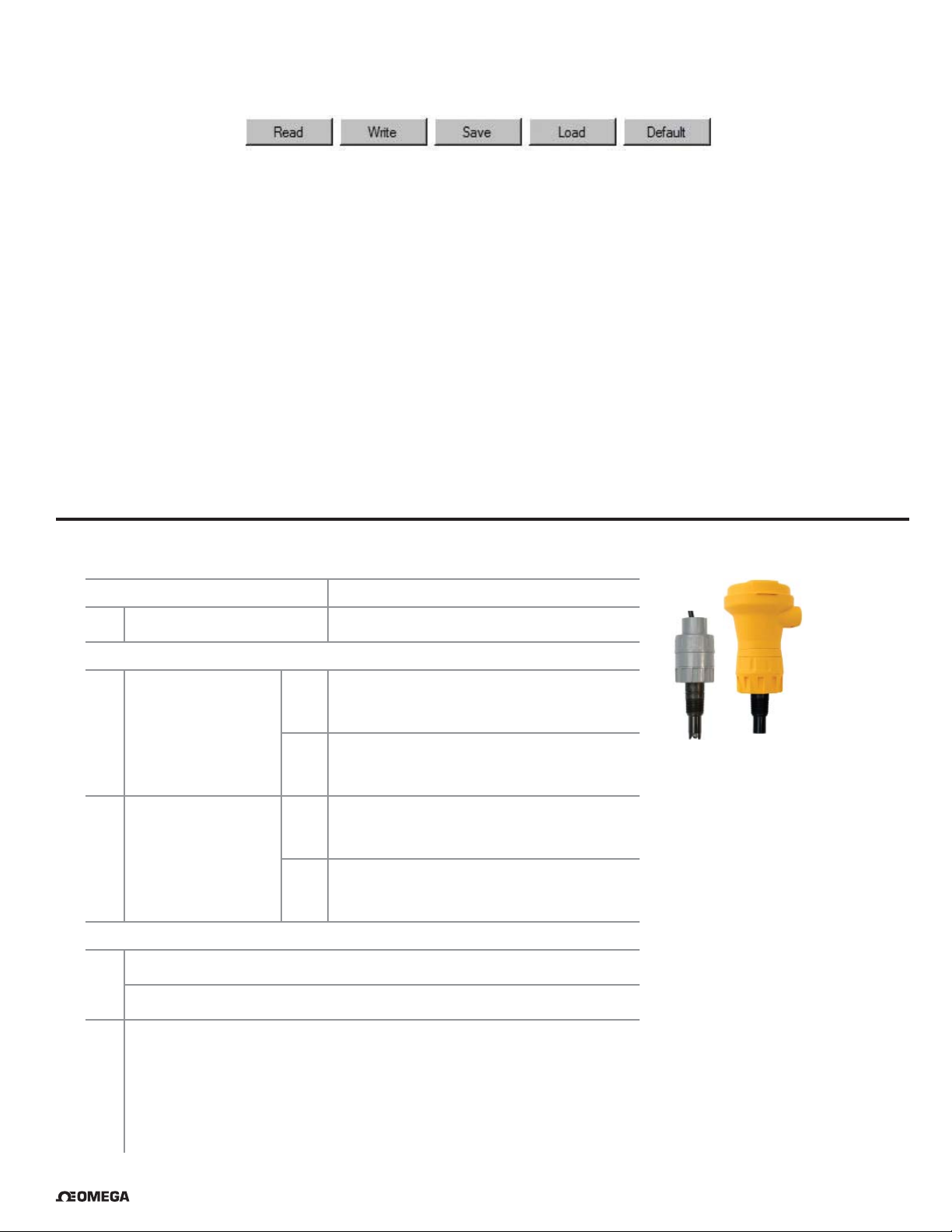
12. General Software Operation
On all screens Read, Write, Save, Load, and Default buttons can be found in the lower right corner.
Read Loads the data from the connected device (sensor or transmitter) and updates the software’s display.
NOTE: This will overwrite any changes made in the DPU90-CT software since the last Write.
Write Applies the data entered in the DPU90-CT software to the connected device. Once you have entered
the desired setting changes in the software screens, press Write to load your new settings onto the
connected device.
Save Stores the entire DPU90-CT settings confi guration, as currently displayed in the application, to a specifi ed
location on your computer. (You will be asked to select a fi le location and provide a fi le name)
Load Opens a previously saved settings confi guration fi le. See Save function above.
NOTE: The fi le must be a DPU90-CT settings confi guration fi le. The software will verify whether the
user-selected fi le is the correct type.
Default Resets all data on all application screens to a factory default condition. A confi rmation dialog box will be
presented with a warning explaining all un-saved confi guration information will be erased. After resetting the
software to a factory default condition, click Write to reset the connected device to a factory default condition.
NOTE: Default will not change the input or instrument type.
13. PHTX-275 & PHEH-275 Operation
Application settings:
1 Engineering units pH or ORP
Loop Output settings:
Min
0 pH (-1000 mV)
2 4 mA Set Point
Max
14 pH (2000 mV)
Min
0 pH (-1000 mV)
3 20 mA Set Point
Max
14 pH (2000 mV)
Write or Save settings:
4a
Click “Write” to copy these settings to the product.
or
Click “Save” to save these settings to a local computer fi le for later use.
4b
PHTX/PHEH-275
5 To use a saved fi le (from 4b):
1. Click “Load”
2. Navigate to the saved fi le
3. Select “Open”
4. Click “Write”
5. Click “Read” to confi rm
®
OMEGA DPU90-CT PC COMM / Sensor Confi guration Tool
7
Page 8
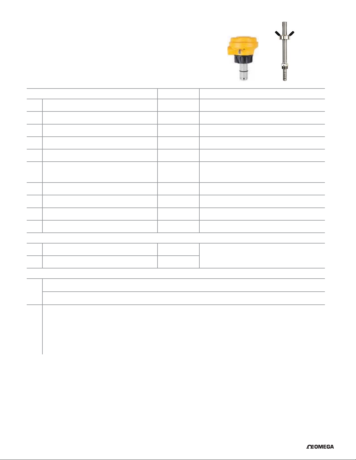
14. FMG-3000 & FMG-550 Operation
Application settings:
Factory
1 Flow Units m m, ft, m
FMG-3000 & FMG-550
3
, L, ft3, US Gal, Imp. Gal, Acre in.
2 Time Base sec Sec, Min, Hour, Day
3 Pipe ID (Inside Diameter) 44.0 0 - 5000
4 Pipe ID Units mm mm, in.
5 K-Factor Units Pulses / Liter Pulses / Liter, Pulses / Gallon
6 K-Factor 65.76670
7 Averaging (in seconds) 14
See Magmeter manuals for appropriate value.
1
/
0.000100 - 999999.1
, ¼, ½, 1, 1½, 3, 7, 14, 25, 50, 100
10
8 Sensitivity (%) 25 100, 50, 30, 25, 20, 15, 10, 8, 5, 2
9 Noise Rejection (Hz) 60 50 or 60
10 Low Flow Cut Off (% of full scale) 0 0 to 20% Full Scale
Loop Output settings:
11 4 mA Set Point (Flow Units / Time Base) 0.00000
0.00000 - 999999.00000
12 20 mA Set Point (Flow Units / Time Base) 5.00000
Write or Save settings:
13a
Click “Write” to copy these settings to the product.
or
13b
Click “Save” to save these settings to a local computer fi le for later use.
14
To use a saved fi le (from 13b):
1. Click “Load”
2. Navigate to the saved fi le
3. Select “Open”
4. Click “Write”
5. Click “Read” to confi rm
8 OMEGA DPU90-CT PC COMM / Sensor Confi guration Tool
®
Page 9
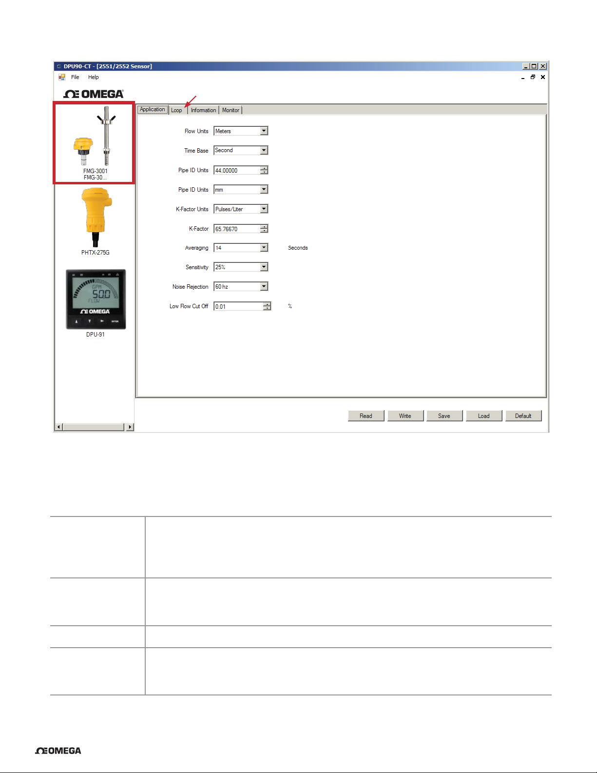
14. FMG-3000 & FMG-550 Operation
11 & 12
1
2
3
4
5
6
7
8
9
10
13a 13b
Notes:
Set the time the Magmeter will use as the averaging period.
Averaging
Sensitivity
Noise Rejection Select 50 Hz or 60 Hz according to local AC power specifi cations.
Low Flow Cut Off
Example: With averaging at 14 seconds, each display is an average of the previous 14
seconds input. Use higher averaging times to smooth the display and current output where
the fl ow in the pipe is erratic.
Set the percentage of change in the fl ow rate required to allow the Magmeter to override
AVERAGING and jump to a new fl ow rate immediately (FMG-3000 max. range is 10 m/s).
See Magmeter manuals for an explanation of Averaging and Sensitivity.
Set the fl ow rate where all Magmeter outputs will be forced to zero.
When the fl ow rate drops below this value, the frequency output will be 0 Hz and the
current output will be 4 mA.
®
OMEGA DPU90-CT PC COMM / Sensor Confi guration Tool
9
Page 10

15. DPU91 Operation
Initiating Communication with the DPU91:
1a Factory Confi gured DPU91 (new or reset):
1. If the display reads "PUSH Enter SELECT SENSOR" the DPU91 is ready for communication.
2. Proceed to step 2 below.
Previously confi gured DPU91:
1b
1. Press and hold ENTER for 3 seconds. The display will change to the MENU mode.
2. Press ▲ once. The OPTION menu will flash. Press ENTER
3. The CONTRAST setting will be displayed.
Press ▲ twice (Gen II, III, IV) or press ▲ once (Gen I) to display REMOTE SETUP.
4. Press ► to edit REMOTE SETUP. If required, enter the security code.
5. Press ▲ to change the fl ashing NO to YES. Press ENTER to confi rm change.
6. REMOTE SETUP should be fl ashing, indicating the DPU91 is ready for communication with the DPU90-CT Tool.
Set Instrument Type:
Select sensor type to be wired to the DPU91 from the
2
drop-down menu at the top of the screen.
Flow, pH, ORP, Conductivity, Salinity, Batch
Application settings:
3 Select the Input, Calibration, Loop, Relay, Options, or Info tabs to choose the desired menu for the selected sensor.
4 Refer to the DPU91 manual for details pertaining to specifi c settings for each sensor type and menu item.
Write or Save settings:
5a
Click “Write” to copy these settings to the product.
or
Click “Save” to save these settings to a local computer fi le for later use.
5b
6 To use a saved fi le (from 5b):
1. Click “Load”
2. Navigate to the saved fi le
3. Select “Open”
4. Click “Write”
5. Click “Read” to confi rm
When confi guration is complete:
7 Disconnect power from the DPU91.
8 Disconnect the DPU90-CT Tool from the DPU91.
9 Reconnect the sensor or reinstall the Direct Conductivity/Resistivity Module.
10 Reconnect Power to the DPU91.
10 OMEGA DPU90-CT PC COMM / Sensor Confi guration Tool
®
Page 11
15. DPU91 Operation
2
3
To confi gure an additional DPU91 Transmitter with the same settings:
11 Click "Save" to save these settings to a local computer fi le.
12 Wire another DPU91 as shown on page 6.
13 Initiate communication with the DPU91 via step 1a or 1b above.
14 Load the saved settings via step 6 at left.
5a 5b
(General Software Operation, page 7)
®
OMEGA DPU90-CT PC COMM / Sensor Confi guration Tool
11
Page 12
16. Datalogger Operation
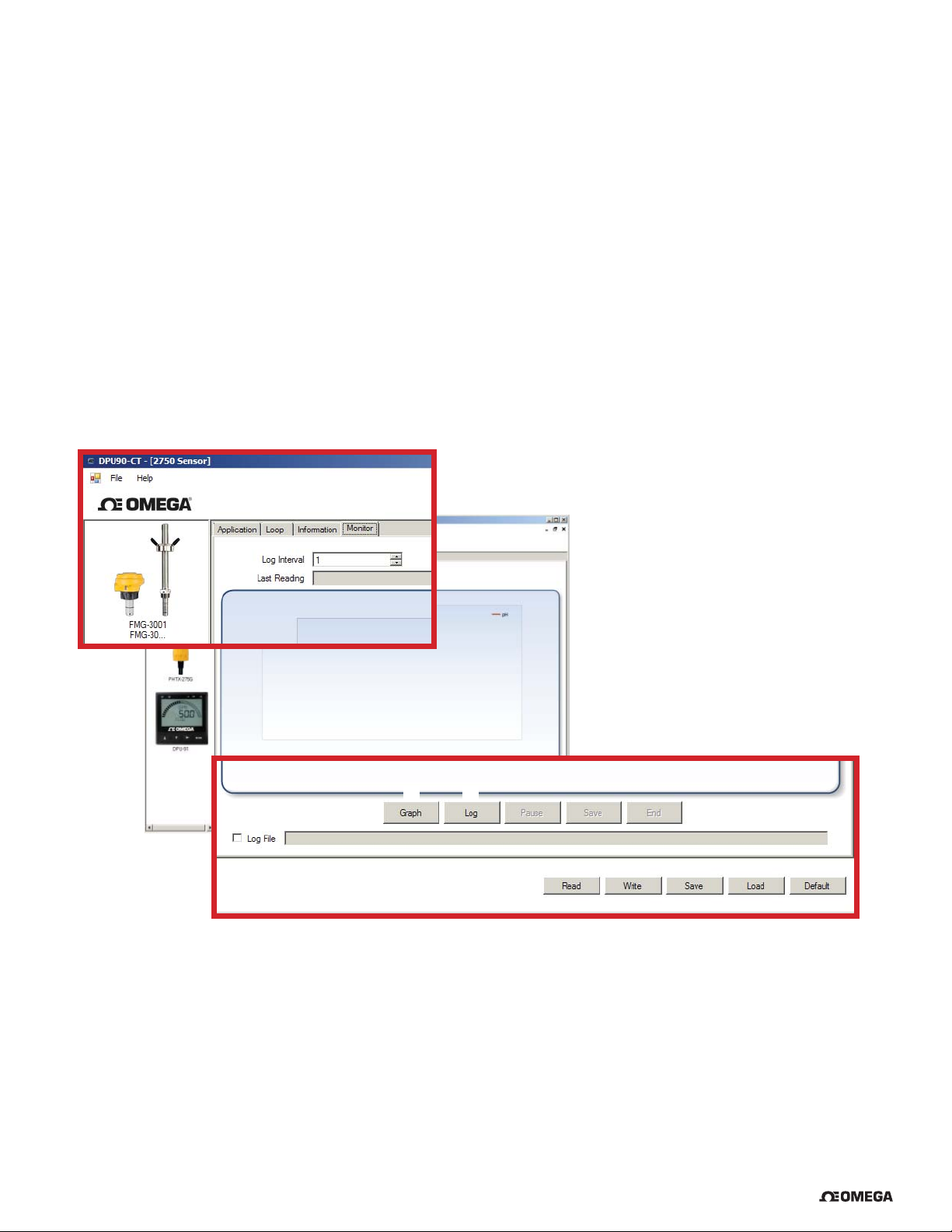
The DPU90-CT can serve as a fi eld data logger to download sensor data directly into a *.csv (Comma Separated Value) fi le.
NOTE: The DPU90-CT does NOT have internal memory to store data. It must be connected to a computer to use the
datalogger function.
IMPORTANT: The DPU-91 Transmitter does not support the datalogger feature.
1. Select the sensor type and click on Read.
2. Click the Monitor tab to open the datalog setup window.
3. Enter the Logging Interval. This value represents the time between log records.
The minimum interval is 1 second, and the maximum interval is 86400 seconds (24 hours).
Example: If the Log Interval is set to 60 seconds, the DPU90-CT will record the sensor data once every minute.
4. The DPU90-CT saves data fi les in *.csv format. The maximum number of records allowed for this type of fi le is
65535 records. If the logging interval is 60 seconds = 1092 hours of continuous recorded data.
5. Click Log and enter the fi le name for the DPU90-CT to store the recorded data and click Save.
6. Click Log File check box to enable logging. If you do not wish to save the data, skip to step 7.
7. Click Graph to start monitoring the sensor.
2
3
57
6
1
12 OMEGA DPU90-CT PC COMM / Sensor Confi guration Tool
®
Page 13

17. Notes
®
OMEGA DPU90-CT PC COMM / Sensor Confi guration Tool
13
Page 14

18. Ordering Information
Mfr. Part No. Description
DPU90-CT PC COMM / Sensor Confi guration Tool
14 OMEGA DPU90-CT PC COMM / Sensor Confi guration Tool
®
Page 15

WARRANTY/DISCLAIMER
OMEGA ENGINEERING, INC. warrants this unit to be free of defects in materials and workmanship for a
period of 13 months from date of purchase. OMEGA’s WARRANTY adds an additional one (1) month
grace period to the normal one (1) year product warranty to cover handling and shipping time. This
ensures that OMEGA’s customers receive maximum coverage on each product.
If the unit malfunctions, it must be returned to the factory for evaluation. OMEGA’s Customer Service
Department will issue an Authorized Return (AR) number immediately upon phone or written request.
Upon examination by OMEGA, if the unit is found to be defective, it will be repaired or replaced at no
charge. OMEGA’s WARRANTY does not apply to defects resulting from any action of the purchaser,
including but not limited to mishandling, improper interfacing, operation outside of design limits,
improper repair, or unauthorized modification. This WARRANTY is VOID if the unit shows evidence of
having been tampered with or shows evidence of having been damaged as a result of excessive corrosion;
or current, heat, moisture or vibration; improper specification; misapplication; misuse or other operating
conditions outside of OMEGA’s control. Components in which wear is not warranted, include but are not
limited to contact points, fuses, and triacs.
OMEGA is pleased to offer suggestions on the use of its various products. However,
OMEGA neither assumes responsibility for any omissions or errors nor assumes liability for
any damages that result from the use of its products in accordance with information provided
by OMEGA, either verbal or written. OMEGA warrants only that the parts manufactured by the
company will be as specified and free of defects. OMEGA MAKES NO OTHER WARRANTIES OR
REPRESENTATIONS OF ANY KIND WHATSOEVER, EXPRESSED OR IMPLIED, EXCEPT THAT OF
TITLE, AND ALL IMPLIED WARRANTIES INCLUDING ANY WARRANTY OF MERCHANTABILITY
AND FITNESS FOR A PARTICULAR PURPOSE ARE HEREBY DISCLAIMED. LIMITATION OF
LIABILITY: The remedies of purchaser set forth herein are exclusive, and the total liability of
OMEGA with respect to this order, whether based on contract, warranty, negligence,
indemnification, strict liability or otherwise, shall not exceed the purchase price of the
component upon which liability is based. In no event shall OMEGA be liable for
consequential, incidental or special damages.
CONDITIONS: Equipment sold by OMEGA is not intended to be used, nor shall it be used: (1) as a “Basic
Component” under 10 CFR 21 (NRC), used in or with any nuclear installation or activity; or (2) in medical
applications or used on humans. Should any Product(s) be used in or with any nuclear installation or
activity, medical application, used on humans, or misused in any way, OMEGA assumes no responsibility
as set forth in our basic WARRANTY/DISCLAIMER language, and, additionally, purchaser will indemnify
OMEGA and hold OMEGA harmless from any liability or damage whatsoever arising out of the use of the
Product(s) in such a manner.
RETURN REQUESTS/INQUIRIES
Direct all warranty and repair requests/inquiries to the OMEGA Customer Service Department.
BEFORE RETURNING ANY PRODUCT(S) TO OMEGA, PURCHASER MUST OBTAIN AN AUTHORIZED
RETURN (AR) NUMBER FROM OMEGA’S CUSTOMER SERVICE DEPARTMENT (IN ORDER TO AVOID
PROCESSING DELAYS). The assigned AR number should then be marked on the outside of the return
package and on any correspondence.
The purchaser is responsible for shipping charges, freight, insurance and proper packaging to prevent
breakage in transit.
FOR WARRANTY RETURNS, please have the
following information available BEFORE contacting
OMEGA:
1. Purchase Order number under which the product
was PURCHASED,
2. Model and serial number of the product under
warranty, and
3. Repair instructions and/or specific problems
relative to the product.
OMEGA’s policy is to make running changes, not model changes, whenever an improvement is possible. This affords
our customers the latest in technology and engineering.
OMEGA is a registered trademark of OMEGA ENGINEERING, INC.
© Copyright 2016 OMEGA ENGINEERING, INC. All rights reserved. This document may not be copied, photocopied,
reproduced, translated, or reduced to any electronic medium or machine-readable form, in whole or in part, without the
prior written consent of OMEGA ENGINEERING, INC.
FOR NON-WARRANTY REPAIRS,
OMEGA for current repair charges. Have
the following information available BEFORE
contacting OMEGA:
1. Purchase Order number to cover the COST
of the repair,
2. Model and serial number of the product, and
3. Repair instructions and/or specific problems
relative to the product.
consult
Page 16

Where Do I Find Everything I Need for
Process Measurement and Control?
OMEGA…Of Course!
Shop online at omega.com
TEMPERATURE
Thermocouple, RTD & Thermistor Probes, Connectors, Panels & Assemblies
Wire: Thermocouple, RTD & Thermistor
Calibrators & Ice Point References
Recorders, Controllers & Process Monitors
Infrared Pyrometers
PRESSURE, STRAIN AND FORCE
Transducers & Strain Gages
Load Cells & Pressure Gages
Displacement Transducers
Instrumentation & Accessories
FLOW/LEVEL
Rotameters, Gas Mass Flowmeters & Flow Computers
Air Velocity Indicators
Turbine/Paddlewheel Systems
Totalizers & Batch Controllers
SM
pH/CONDUCTIVITY
pH Electrodes, Testers & Accessories
Benchtop/Laboratory Meters
Controllers, Calibrators, Simulators & Pumps
Industrial pH & Conductivity Equipment
DATA ACQUISITION
Communications-Based Acquisition Systems
Data Logging Systems
Wireless Sensors, Transmitters, & Receivers
Signal Conditioners
Data Acquisition Software
HEATERS
Heating Cable
Cartridge & Strip Heaters
Immersion & Band Heaters
Flexible Heaters
Laboratory Heaters
ENVIRONMENTAL
MONITORING AND CONTROL
Metering & Control Instrumentation
Refractometers
Pumps & Tubing
Air, Soil & Water Monitors
Industrial Water & Wastewater Treatment
pH, Conductivity & Dissolved Oxygen Instruments
M-5327/0816
 Loading...