

Page 1
http://www.omega.com
e-mail: info@omega.com
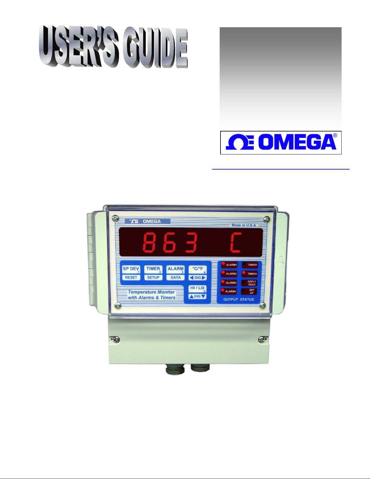
DPS3301
Series
Wall-Mount Programmable
Temperature Monitor
Page 2

SPECIFICATIONS.......................................................................................................................................................... 4
DESCRIPTION................................................................................................................................................................ 5
THERMOCOUPLE OR RTD SELECTION................................................................................................................. 5
HOW TO RESET AND PROGRAM THERMOCOUPLE TYPE (OR RTD).................................................................................. 6
FIGURE 1. THERMOCOUPLE/RTD SELECTION KEYS ..................................................................................................... 6
DISPLAY MODES........................................................................................................................................................... 6
RETAINING USER SETTINGS ON POWER DOWN................................................................................................ 7
DISPLAY UNITS C/F:.................................................................................................................................................... 7
SETPOINT DEVIATION: .............................................................................................................................................. 7
DISPLAY HOLD FEATURE: ........................................................................................................................................ 7
FLOW CHART ................................................................................................................................................................ 8
SETUP MODE................................................................................................................................................................. 9
ENTERING AND EXITING SETUP MODE:.......................................................................................................................... 9
HOW TO INCREASE/DECREASE PROGRAMMABLE VALUES IN SETUP .............................................................................. 9
PASSCODE ENTRY:..........................................................................................................................................................9
'PROGRAM CONTROLLER' MODE........................................................................................................................ 10
DISPLAY TIME............................................................................................................................................................... 10
DISPLAY OPTION:.......................................................................................................................................................... 10
RATE TIME-BASE:......................................................................................................................................................... 10
COLD JUNCTION ADJUSTMENT: ..................................................................................................................................... 11
THERMOCOUPLE CALIBRATION:.................................................................................................................................... 11
THERMOCOUPLE TYPE SELECTION: ............................................................................................................................... 12
‘PROGRAM LIMITS’ MODE:.................................................................................................................................... 12
PROCESS LIMITS (1 THRU 4):......................................................................................................................................... 12
SELECTION OF LIMIT 3 AS PROCESS OR RATE LIMIT:..................................................................................................... 12
PROGRAMMING LIMIT 3: ............................................................................................................................................... 13
As Process Limit:...................................................................................................................................................... 13
As Rate Limit:........................................................................................................................................................... 13
SELECTION OF LIMIT 4 AS PROCESS OR DEVIATION LIMIT: ........................................................................................... 13
PROGRAMMING LIMIT 4: ............................................................................................................................................... 13
As Process Limit:...................................................................................................................................................... 13
As Deviation Limit:................................................................................................................................................... 13
CONFIGURE TIMING MODE............................................................................................................................................ 13
TIMERS 1 AND 2: ........................................................................................................................................................... 14
RELAY DEADBAND: ...................................................................................................................................................... 14
CONFIGURING LIMITS NORMALLY OPEN/NORMALLY CLOSED:.................................................................................... 14
RELAY LATCHING/NON LATCHING:............................................................................................................................... 14
AUDIO ALARM ON/OFF:................................................................................................................................................ 15
RATE............................................................................................................................................................................... 15
RATE ALARM:............................................................................................................................................................... 15
RESETTING RATE ALARM: ............................................................................................................................................ 15
SETPOINT DEVIATION ALARM: ............................................................................................................................ 15
DEVIATION ALARM:...................................................................................................................................................... 16
RESETTING DEVIATION ALARM:...................................................................................................................................16
PROCESS ALARMS.....................................................................................................................................................16
DISPLAYING:................................................................................................................................................................. 16
2
Page
Page 3

RESETTING:................................................................................................................................................................... 16
ELECTRO-MECHANICAL RELAY OPTION ....................................................................................................................... 16
Figure 2. Electro-mechanical Relays Hookup Example........................................................................................... 17
OPEN COLLECTOR OPTION............................................................................................................................................ 17
Figure 3. Open Collector Hookup Example............................................................................................................ 17
TIMERS.......................................................................................................................................................................... 17
RESETTING TIMERS:...................................................................................................................................................... 18
TIMER MODES............................................................................................................................................................. 18
TIMER MODE #0............................................................................................................................................................ 18
TIMER MODE #1............................................................................................................................................................ 18
TIMER MODE #2............................................................................................................................................................ 18
ELAPSED TIME........................................................................................................................................................... 18
HOW TO RESET ELAPSED TIME...................................................................................................................................... 18
HIGH AND LOW PEAKS ............................................................................................................................................ 19
HOW TO RESET HIGH & LOW PEAK READINGS.............................................................................................................. 19
OUTPUT STATUS:........................................................................................................................................................ 19
POWER........................................................................................................................................................................... 19
SIGNAL CONNECTION.............................................................................................................................................. 19
OUTPUT CONNECTOR PIN ASSIGNMENT.......................................................................................................... 20
TABLE 1. OUTPUT CONNECTOR PIN ASSIGNMENT...................................................................................................... 20 T
FIG 4. DPS3301 SERIES TERMINAL COMPARTM E NT...................................................................................... 21
DIRECT INTERFACE TO UNIVERSAL RELAY MODULE................................................................................. 21
DIRECT INTERFACE TO UNIVERSAL RELAY MODULE................................................................................. 22
MOUNTING................................................................................................................................................................... 23
3
Page
Page 4

SPECIFICATIONS
Typical @ 25 C and rated supply voltage unless otherwise specified.
INPUTS:
• Input types: J,K,T,E,R,S,B t/c, RTD, Voltage, Millivolt, Current & thermistor
• Cold junction compensation error: +/- 0.5C max (10C to 40C)
• Open thermocouple indication: ‘OPEN TC’ displayed
OPTIONS:
• 240Vac @ 50 Hz Power Supply
• 15Vdc @ 1000ma. Power Supply
• Open Collector output: 6 open collector transistors @ 50ma. sink each
• Relay output: 6 SPST 1 Amp. @ 28Vdc, 0.5 Amp. @ 120Vac (resistive load)
(for 220 Vac units only 0.25Amp.@ 240Vac (resistive load))
ACCURACY:
• Temperature resolution: 1 C/1 F, 0.1C for Thermistor
• 0.1% of Full Scale (Base metal T/C), 0.5% others
ANALOG TO DIGITAL CONVERSION:
• 4 1/2 Digit (20000 count) A/D conversion.
• Dual slope integrating converter.
• Conversion Rate: 7 /sec. typical
POWER REQUIREMENTS:
• 120Vac, 0.2 Amp. @ 60 Hz
DIMENSIONS:
• Case: 7.55"W x 6.29"H x 4.05"D
•
IP65 rated plastic enclosure
• Weight: 2.63 lb. (1.19kg.)
• Enclosure: All Plastic enclosure—IP65 Ingress Protection
DISPLAY:
• Red 7-segment LED display, 0.39 inch (10mm) digit height
• Negative polarity indication
• Out of range indication: HELP
• Display Test: Briefly displays 8.8.8.8.8.8.8. on power up
RELIABILITY:
• Calibration: NIST traceable
• Recalibration: Recommended at 12 months interval
4
Page
Page 5

DESCRIPTION
Housed in a wall-mount, water-tight plastic enclosure, the DPS3301 Series is a powerful temperature
monitor/indicator. It accepts a single Thermocouple, RTD or Thermistor sensor input and then displays the
temperature in either degrees C or F. In addition, it also monitors a number of useful functions such as high
and low process readings, process run time, rate of process change etc.
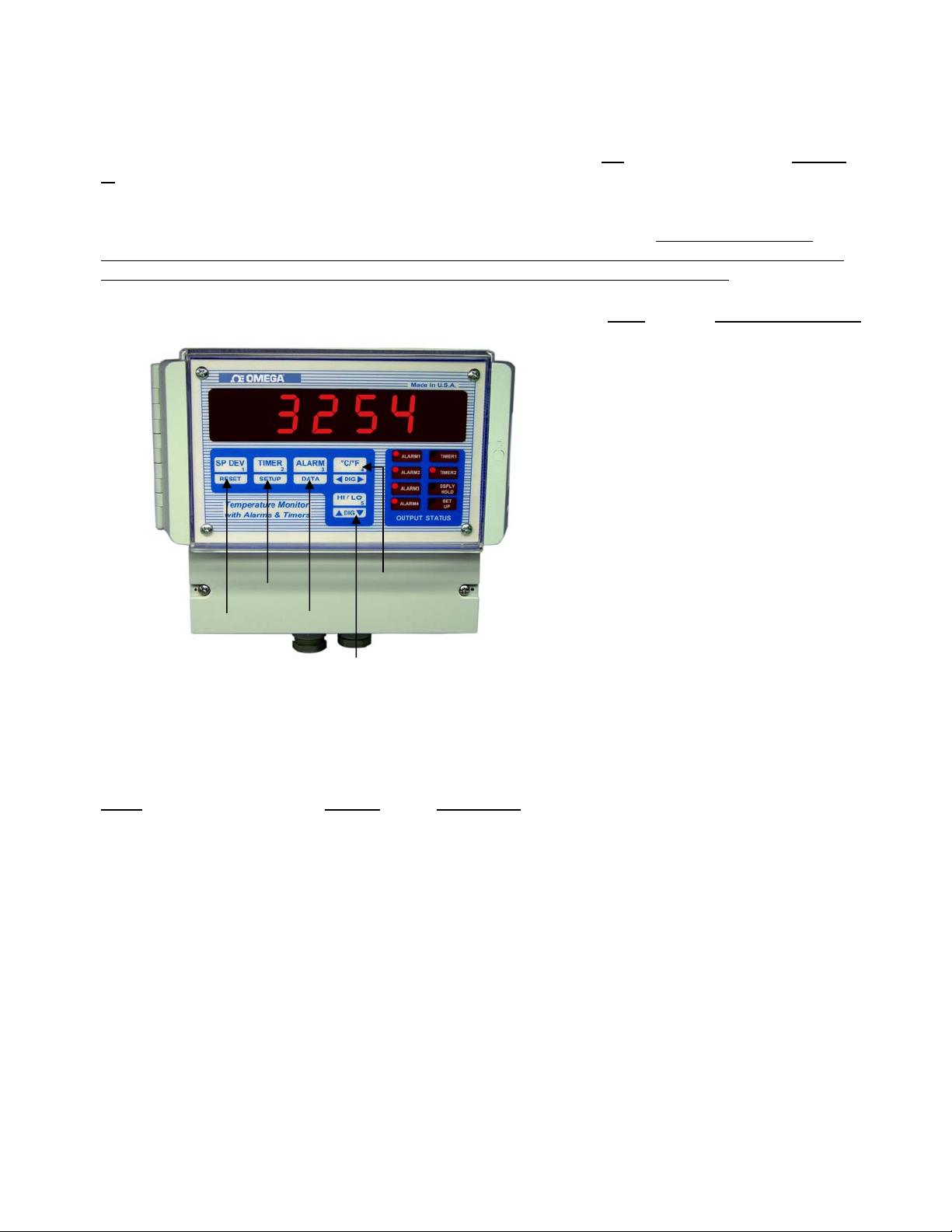
Keys are appropriately labeled, so that the user would not have to memorize their functionality. A passcode
requirement keeps unauthorised personel from changing critical parameters such as limits, timers etc.
The DPS3301 also functions as a rate monitor, indicating instantaneous as well as average rate of
temperature change. Programmable time base allows the rate to be displayed in per second, minute, hour or
any other interval. Also, the unit can be programmed for a rate alarm. This allows control of a process if a
predetermined rate is exceeded or not achieved. The time function keeps track of process run time.
Maximum and minimum temperature readings are constantly tracked and can be helpful in quality control or
monitoring unattended processes (e.g. overnight).
Various process parameters monitored by the system may be displayed by pushing the appropriate keys on
the front panel, e.g. (Rate, Peak etc.). The respective parameter will be displayed as long as the key is kept
pressed. Alternately, if the key is pressed and then released, the unit will display a particular parameter
briefly and then go back to temperature display mode.
Four process alarms (optional) are also featured, which are programmable over the entire range of selected
input type. Also provided are two timers (optional) that work independently or in conjunction with process
limits e.g. turning on a fan ten minutes after limit 1 temperature is reached.
Process limit relays may be operated in two different modes:
1. Non-latching mode, in which the relays reset automatically as soon as the temperature
falls below the limit (minus the relay dead-band).
2. Latching mode, in which the relays stay energized even after the temperature falls below
the programmed limit. In this mode the relays will stay on until manually reset.
THERMOCOUPLE OR RTD SELECTION
DPS3301 instruments ordered for Thermocouples or RTD’s can be programmed through the front panel keys
to work with one of these specific inputs (Input type or options depend on Model number ordered).
When DPS3301 is first turned on, a ‘display segment test’ is done by briefly displaying 8.8.8.8.8.8.8.,
followed by the software revision number (rEn X.XX) and input signal type.
J (R,S,B, rtd 385, Thermistor, J tC (r, S, B, rtd 385, tHrStor,
Millivolt, Voltage, Current) Lo VoLt, HI VoLt, CurrEnt)
K (rtd 392) Cr.AL tC (rtd 392)
T t tC
E E tC
Factory default thermocouple/RTD selection can be obtained as explained below:
Input type Display shows:
5
Page
Page 6
r
How to Reset and Program Thermocouple Type (or RTD) How to Reset and Program Thermocouple Type (or RTD)
A DPS3301-TC that is calibrated for a J, K, T, or E type thermocouple or an RTD model may be
A DPS3301-TC that is calibrated for a J, K, T, or E type thermocouple or an RTD model may be
programmed for a specific thermocouple, or RTD (385/392) type, by going into SETUP mode (Look under
programmed for a specific thermocouple, or RTD (385/392) type, by going into SETUP mode (Look under
‘SETUP’). Alternately, a thermocouple/RTD may be selected by turning
‘SETUP’). Alternately, a thermocouple/RTD may be selected by turning
in the appropriate key (see Figure 1). This procedure also clears the memory and programs factory defalult
values for limits, rate timebase etc. Therefore, after performing Power-up reset, various parameters such as
limits, rate time base etc., must be re-programmed to a desired value. However, if done in SETUP mode, no
programmed parameters such as limits, Timers etc. are erased from the memory.
thermocouple (RTD) selection be done in SETUP. Power-up reset should be performed if it is suspected that
program memory may have been corrupted due to power surge, noise on electrical lines etc.
FIGURE 1. Thermocouple/RTD Selection Keys
Memory Clear only T t/c
E t/c
K t/c, RTD392,
Thermisto
J (R, S or B) t/c,
RTD385
On
On power to the unit while holding
It is recommended that
KEY Input Type Selected
HI/LO J (R, S or B , RTD 385)
Thermistor
C/F K (RTD 392)
ALARM T
TIMER E
RESET Memory cleared – no
factory default values
. programmed.
NOTE: All keys, except RESET, clear
memory and program necessary factory
default values. RESET key clears memory
only and programs no default values.
However, previous thermocouple type is
retained.
DISPLAY MODES
The DPS3301 can be programmed to display in any one of the following modes:
Mode Display Description
PROCESS PrOCESS
SETPOINT DEVIATION SP. DEVN
INSTANTANEOUS RATE In. rAtE
PROCESS HIGH Pr. HIGH Displays process’ highest reading
PROCESS LOW Pr. LO Displays process’ lowest reading
ELAPSED TIME ELPSd. T Displays elapsed time.
TIMER 1 COUNT DOWN tr1. Cnt Display Timer 1 count down value
TIMER 2 COUNT DOWN tr1. Cnt Display Timer 2 count down value
SCAN SCAn Scans through all the above parameters
Displays Instantaneous rate value.
Displays process value.
Displays setpoint deviaition.
6
Page
Page 7
SEE SETUP ON HOW TO SELECT ONE OF THE DISPLAY MODES.
RETAINING USER SETTINGS ON POWER DOWN
DPS3301 saves all the programmed parameters in an EEPROM (electrically erasable programmable read
only memory). An EEPROM stores the programmed parameters even when the power is removed from the
unit. However, it is important to note that if the parameters are being changed during setup, they must be
saved in the EEPROM by
under SETUP. If parameters are
values will be lost ( the unit will, however, maintain the old values).
pressing and holding the ‘RESET’ key (till SAVING is displayed) as described
NOT saved and the power is removed from the unit, any newly changed
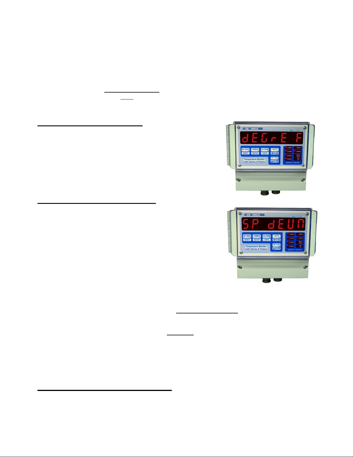
DISPLAY UNITS C/F:
DPS3301 units can display temperature in either degrees
Centigrade of Fahrenheit. To switch the display from Fahrenheit
to Centigrade or vice versa, simply push the C/F key once. The
display will read ‘dEGrE F’ if the unit enters degrees Fahrenheit
mode. It will display ‘dEGrE C’ if Centigrade mode is enabled.
Following the message, the unit will start displaying temperature
in selected engineering units.
SETPOINT DEVIATION:
A useful feature of DPS3301 units is tracking of a setpoint
relative to process value at any given point in time. To display
deviation, push the key labeled ‘SP DEV’ once. The display will
read ‘SP DEVN’ following which the deviation reading will be
shown. A second push on the same key while it is displaying
deviation will indicate the current setpoint value.
Setpoint value that needs to be tracked can be entered in two
different ways. One is during setup mode and the other is using
the front key labled ‘SP DEV’. SETUP mode entry is used when
a particular value needs to be programmed e.g. 500, 850 and so
on. To enter Setpoint in this mode, look under ‘SETUP’.
If it is desired to start tracking setpoint deviation from
used. Assume that current reading on the display is 476 F. To enter this temperature as your setpoint, first
push ‘SP DEV’ key twice (first push displays deviation from current setpoint, and the second push displays
current SETPT value). After the second push keep
display will flash the message ‘SETPT’ three times. Following the third flash, the unit will take the current
process reading and save it as the new SETPOINT. If the process reading is 500, then taking our above
example, pushing ‘SP DEVN’ key will display 24 as your deviation value. Note that if ‘SP DEVN’ key is
released before three flashes of ‘SETPT’ message, the unit will not enter a new setpoint. However, old
setpoint value will be retained in the memory.
current process reading then front key entry mode is
holding in the ‘SP DEV’ key. After a brief delay the
DISPLAY HOLD FEATURE:
DPS3301 offers a display hold feature. When ever pins 13 and 14 are shorted together (e.g. through a remote
switch), the reading taken at the time of shorting is frozen on the display. The unit will continue displaying
this value until the short is removed. This is indicated by the display periodically flashing the message ‘Pr
HoLD’. Internally the unit keeps monitoring the actual process and limits and timers will be activated if
process exceeds their programmed values. However, the display will indicate the hold temperature.
7
Page
Page 8
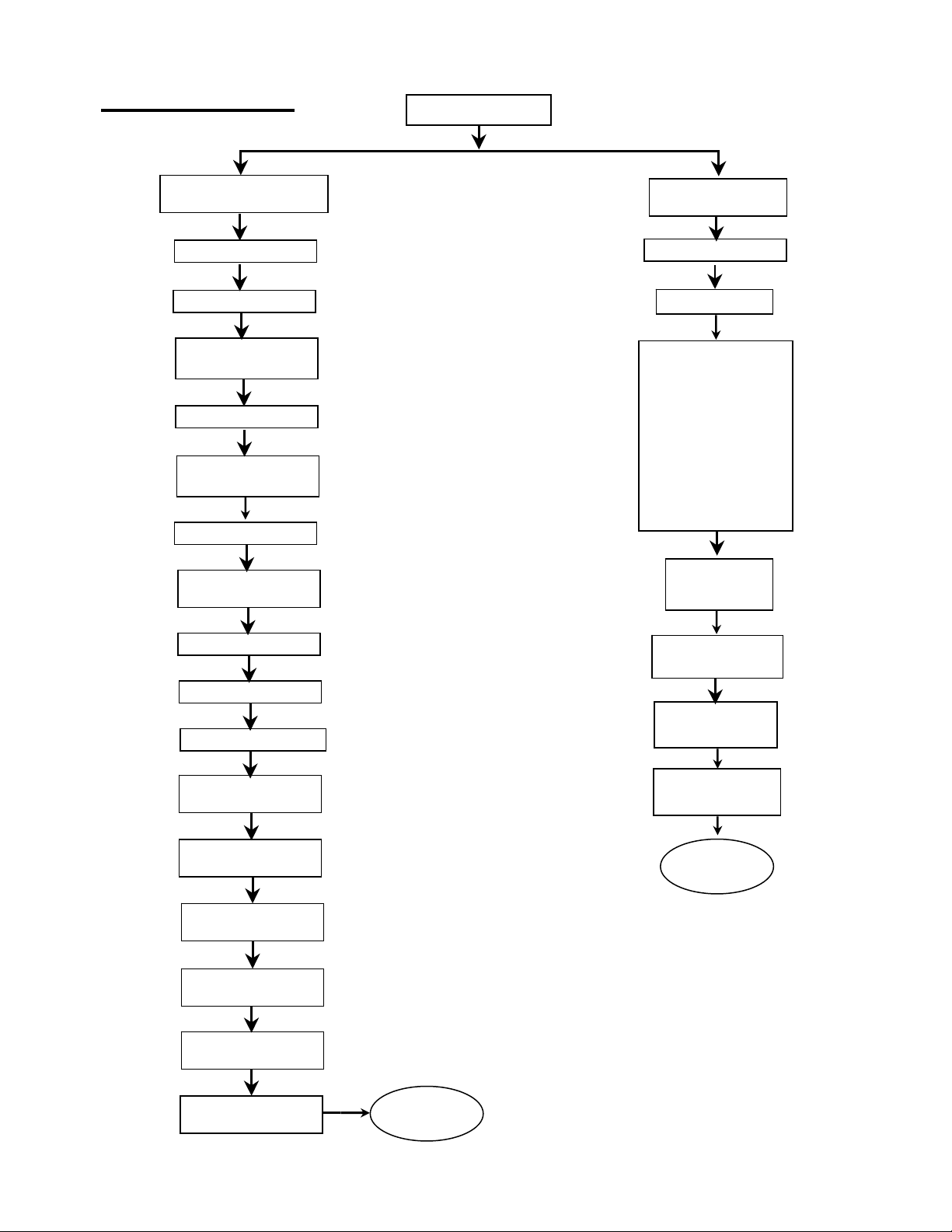
FLOW CHART
PROGRAM LIMITS
PROGRAM LIMIT1
PROGRAM LIMIT2
Configure Limit3 as
Process or Rate
PROGRAM LIMIT3
Configure Limit4 as
Process or Deviation
PROGRAM LIMIT4
SETUP
PROGRAM
CONTROLLER
SETPT
DISPLAY TIME
DISPLAY OPTION
a. Process
b. Setpt Devn.
c. In. Rate
d. Process High
e. Process Low
f. Elapsed Time
g. Timer 1 Count
h. Timer 2 Count
i. Scan all
Select Timer Modes
0,1 or 2
PROGRAM TIMER1
PROGRAM TIMER2
RELAY DEADBAND
Limit1 Normally open
or closed
Limit2 Normally open
or closed
Limit3 Normally open
or closed
Limit4 Normally open
or closed
RATE
TIMEBASE
COLD JUNCTION
CALIBRATION
INPUT
CALIBRATION
INPUT
SIGNAL TYPE
Back to
SETUP
Limits Latching or
Non-Latching
Audio Alarm ON or
OFF
Back to
SETUP
Page
8
Page 9

SETUP MODE
Setup is used for configuring various parameters of DPS3301 unit.
These parameters include entering limits, timers, dead-bands etc.
Entering and Exiting Setup Mode:
To get into setup mode, press and hold SETUP key. The display will
show ELPSd t and then the value of elapsed time. Keep holding-in
‘SETUP’ key till the display shows ‘SETUP’ and starts scrolling the
message 'EntEr PASSCOdE'.
To return from SETUP to normal display/run mode, simply push and
hold down the ‘RESET’ key. On exiting, the display will briefly show
'SAVING' to indicate that the new data is being saved in nonvolatile
memory (key should be held in until the word ‘SAVING’ shows up on
the display). Setup mode is also exited automatically if no key action is
detected for about 5 minutes. On automatic exit, all the changes made
up to that point are saved in the permanent memory.
How To Increase/Decrease Programmable Values in
Setup
Once a parameter is displayed (e.g. 01234), the ‘^DIG v’ key can then be used for increasing or decreasing
the value of the flashing digit. For incrementing, push and
‘^DIG v’ key and immediately push it (and
to the next digit, push ‘<DIG>’ key till the desired digit starts flashing.
Again, use ‘^DIG v’ key to change its value.
hold in) again. To move on
Passcode Entry:
Passcode entry is a four digit number which keeps unauthorized
personnel from changing the unit’s parameters. Front panel keys are
each marked with a small digit in the lower right corner. For the five
keys there are five digits --- 1,2,3,4,5. Pass-code is a combination of
these digits and for DPS3301 units the pass-code to program
parameters is 3254. Three attempts at entering the correct pass-code are
allowed. Anytime a wrong digit is entered, the display will read HELP.
If correct pass-code is not entered within three attempts, the system will
exit SETUP and return to normal display mode. To make another attempt,
you have to get into setup again by holding in ‘SETUP’ key.
As soon as correct four digit pass-code is entered, the unit is ready for
setup. At this point the unit will display ‘PrG Ctr’ (for 'Program
Controller'). Available options at this point are:
1. PrG Ctr (for 'Program Controller’) 2. PrOG Lt (for 'Program
Limits')
The unit starts with 'Program Controller’ as the active mode (displaying
PrG Ctr). To select alternate mode, push ‘^DIG v’ key. Once the
desired mode is displayed, push ‘SETUP’ key to select it.
Page
hold in ‘^DIG v’ key. To decrement, release
new
‘PROGRAM CONTROLLER’ MODE
9
Page 10

'PROGRAM CONTROLLER' MODE
Display Time
On entering Program Controller mode, the very first step lets you
program is the display time. This determines the length of time (in
seconds) that any
‘PROCESS’ is flashed.
The unit will first show 'dSPLy t' (for Display Time), and then the
current setting in seconds. Use ‘^DIGv’ and ‘<DIG>’ key to set the
desired display time. Push ‘SETUP’ key following the selection.
Display Option:
This is indicated by the display briefly reading 'dSP OP
display option) and then the currently selected Option. Use ‘^DIGv’
key to step thru various options. Once the desired option has been
selected, push ‘SETUP’ key to enter it and go on to set Display Time.
Display Mode Display shows Description
PROCESS PrOCESS
SETPOINT DEVIATION SP. DEVN
INSTANTANEOUS RATE In. rAtE
PROCESS HIGH Pr. HIGH Displays process’ highest reading
PROCESS LOW Pr. LO Displays process’ lowest reading
ELAPSED TIME ELPSd. T Displays elapsed time.
TIMER 1 COUNT DOWN tr1. Cnt Display Timer 1 count down value
TIMER 2 COUNT DOWN tr1. Cnt Display Timer 2 count down value
SCAN SCAn Scans through all the above parameters
Rate Time-Base:
This step is for programming time-base for calculation of Rate. Units
of time-base are seconds. Again, the active digit will be flashing.
Message displayed before the value is “rATE tb:. To change the
value, push ^v key. To activate another digit for change, use <DIG>
key. On finishing, push SETUP key.
VALUE is displayed before message, such as
t' (for
Displays process value.
Displays setpoint deviaition.
Displays Instantaneous rate value.
10
Page
Page 11

Cold Junction adjustment:
After setting Heat/Cool mode, the next parameter is the cold
junction reference temperature adjustment. The display will first
show 'COLd JN' , and then the cold junction temperature will be
indicated. Use ‘^DIGv’ key to adjust until the display reads the
proper temperature. Once the correct temperature is displayed, push
‘SETUP’ key to enter that setting and go to temperature Calibration
mode.
NOTE 1: The unit comes pre-calibrated from the factory.
However, the above procedure can be used if any adjustment is
required to the Cold-junction reading.
NOTE 2: Cold-junction temperture is the temperature of the connector that connects the thermocouple to
the unit. This temperature is usually higher than ambient temperature, particularly after the unit has been
powered for some time. This is due to the heat generated by internal electronics of the unit. For precise
calibration, measure the temperature at thermocouple connector and then adjust Cold-junction reading.
NOTE 3: No cold-junction calibration is required for RTD or thermistor units. Therefore, this step is
omitted in RTD or Thermistor units.
Thermocouple Calibration:
For base-metal thermocouples (type J, K, T and E), calibrating one
type of thermocouple calibrates all. While calibration can also be
performed outside of setup procedure (in main Process display mode),
doing this in ‘SETUP’ eliminates flashing ‘PROCESS’ message from
interupting the procedure. Also, raw A/D input can be viewed in this
mode by pushing ‘SETPT’ key. This allows for adjusting any offset
errors and thus allows for more precise calibration.
Thermocouple Calibration Procedure
Note: Make sure the unit is reading correct cold-junction temperature before calibrating.
If incorrect, adjust as described in the " Cold Junction adjustment" section.
For thermocouple calibration (type J T/C), following steps should be performed. Note that only one
type of thermocouple need to be calibrated (i.e. J,K,T or E). For example, if the calibration is done for a type
K thermocouple, types J, T, and E are automatically calibrated.
1.
Connect a thermocouple calibration source to the signal input connector.
2.
Dial in 725 degrees centigrade (Note: unit must be programmed for displaying in
centigrade).
3.
Adjust gain pot on the back of the instrument (ref. Fig. 7, Pg. 21) until the display reads
'725'.
4.
Short the input connector with a wire or shorting bar (make sure the source is removed so
as not to damage it --- shorting the input connector will short the output of the source).
5.
Push ‘SETPT’ key. The display will read 'U 00002' --- or some other value.
6.
Adjust offset pot on back of instrument (ref. Fig. 7, Pg. 21) until the display reads '0000'.
7.
Push SETUP key once -- the display should read close to Cold Junction temperature.
8.
Remove the shorting bar from the input and connect the thermocouple calibrator again.
9.
Repeat steps 2 through 7 till the unit reads proper temperature.
11
Page
Page 12

NOTE 1: The unit must be powered up for at least ten minutes before any adjustments are made.
NOTE 2: For calibrating units with RTD or Thermistor inputs, connect the source to input connector, dial in
a temperature near high end of the scale and adjust gain potentiometer on the back of the unit (See figure 7
for reference).
Thermocouple type Selection:
Next function is the last one in system setup. Here you select the type of thermocouple for which the unit has
been calibrated. First the display shows the message ‘IP tYPE’ (for ‘Input Type’) followed by current
thermocouple selection. For various thermocouples the unit reads:
Thermocouple type Display shows
J T/C J tC
K T/C Cr.AL tC
T T/C t tC
E T/C E tC
For units with RTD input, the selection is between RTD 392 or RTD 385. Thermistor units display
‘tHrStOR’ (for ‘Thermistor’) and units with R, S and B type thermocouples display ‘r tC’, ‘S tC’ and
‘b tC’ respectively with no selection option (since these units offer only one type of input)
To make an alternate selection, push ‘^DIGv’ key. After making the selection, push ‘SETUP’ key. This
last push will take you to the very beginning of setup mode with the display reading 'PrG Ctr’. At this
point either push RESET key to get out of setup or select any other option as described before.
‘PROGRAM LIMITS’ MODE:
Process Limits (1 thru 4):
If selection made from programming group is for ‘PROG LT’
then the very first parameter programmed is process limit 1.
This is indicated by the message ‘PrG. LT1’ followed by preprogrammed value of the limit. Again, use ‘<DIG>’ key to
move flashing to the next digit and ‘^DIGv’ key to
increment/decrement value of the flashing digit.
The procedure for programming limits 2,3 and 4 are very
similar to limit 1 (
limits). However, limits 3 and 4 can be configured to work as
rate and deviation limits. If such is the case, then, after
programming limit 2, the next step takes us into selection of
limit 3 as rate or process limit.
Selection of Limit 3 as Process or Rate Limit:
This step comes after programming Limit 2 and is indicated by
the message ‘LT3 RTE’ (if Limit 3 is setup as Rate limit) or
‘LT3 Pr’ (if Limit 3 is setup as Process limit). Alternate
selection can be made by pushing ‘^DIGv’ key. Push ‘SETUP’
key after making the selection.
provided Limits 3 and 4 are setup as process
12
Page
Page 13

Programming Limit 3:
As Process Limit:
If Limit 3, in the above step, was configured as a Process limit, then the message displayed on entering this
mode will be ‘PrG Lt3’. This will be followed by displaying the current value of Limit 3 . Use ‘<DIG>’
key to move flashing to the next digit and ‘^DIGv’ key to
increment/decrement the value of flashing digit.
As Rate Limit:
If Limit 3, in the above step, was configured as a Rate limit, then
the message displayed on entering this mode will be ‘RATE Lt’.
This will be followed by displaying the current value of Limit 3 .
Use ‘<DIG>’ key to move flashing to the next digit and ‘^DIGv’
key to increment/decrement the value of the flashing digit.
Selection of Limit 4 as Process or Deviation
Limit:
This step comes after programming Limit 3 and is indicated by the message ‘LT4 Pr’ (if Limit 4 is setup as
Process limit) or ‘LT4 dEN’ (if Limit 4 is setup as deviation limit). Alternate selection can be made by
pushing ‘^DIGv’ key. Push SETUP key after making the selection.
Programming Limit 4:
As Process Limit:
If Limit 4, in the above step, was configured as a Process limit,
then the message displayed on entering this mode will be ‘PrG
Lt4’. This will be followed by displaying the current value of Limit
4 . Use ‘<DIG>’ key to move flashing to the next digit and
‘^DIGv’ key to increment/decrement the value of the flashing
digit.
As Deviation Limit:
If Limit 4, in the above step, was configured as a Deviation limit, then the message displayed on entering this
mode will be ‘dEVN Lt’. This will be followed by displaying the Limit 4 value . Use ‘<DIG>’ key to
move flashing to the next digit and ‘^DIGv’ key to increment/decrement the flashing digit.
Configure Timing Mode
DPS3301 is equipped with 2 versatile timers that may be
programmed to operate in 3 different modes, referred to as Timer
Mode 0, 1, or 2.
Mode 0 is an elapsed time mode in which the timer starts running
as soon as the instrument is turned on or the timer is reset. After
the programmed amount of time has elapsed, the timer output is
13
Page
Page 14

energized.
In Mode 1 the timer is ON for a programmed amount of time after a temperature limit is reached (limit1
for Timer 1 and Limit 2 for Timer 2). When programmed amount of time has elapsed, the timer is deenergized.
Mode 2 is used to produce a programmable time delay after the temperature limit is reached. After the
delay, the timer output comes ON and stays ON until reset by the operator. For more details, refer to the
TIMER MODES section.
This mode is indicated by tr 0, tr 1 or tr 2 for timer mode 0, 1, or 2.
Use DIG key to select desired timer mode.
Timers 1 and 2:
This mode lets you enter values for timer 1 and 2. The display will
read ‘TR1 LT’ (for timer 1 limit) and ‘TR2 LT’ (for timer 2 limit)
followed by current programmed value of each of the timers. To
change the value use ‘<DIG>’ key in conjunction with the ‘^DIGv’
key. Once done, push ‘SETUP’ key to go to the following parameter.
Relay Deadband:
The parameter programmed after timers is limit deadband. The display
will first read "DEAD BD" and then show the value of previously
programmed dead-band. To change the value of flashing digit, press ^v
key. To move flashing digit, push <DIG> key. After programming the
desired value of "dead-band" push ‘SETUP’ key to get to the next
function.
Configuring Limits Normally Open/Normally Closed:
Following relay deadband, the alarm outputs are configured as normally closed or normally open. This will
be indicated as ‘LT1 N.O.’ ( if limit 1 is programmed as normally open) or ‘LT1 N.C.’ (if limit 1 is
programmed as normally closed). To make an alternate selection, push the ‘^DIGv’ key. After selecting or
to retain current setting, push ‘SETUP’ key. The following three steps are similar to the last step and in it
limits 2,3 and 4 are setup as normally open or normally closed.
Relay Latching/non Latching:
The next function is configuration of relays as latching or nonlatching. In non-latching mode, the relays will reset automatically
when the process variable drops below the programmed limit. In the
latching mode once the relays are energized they have to be reset
manually even though the process variable might have fallen below
the limit ( latching/non-latching mode is only for process, rate and
deviation limits). If the system is in latching mode the display will
read ‘LATCH’. Alternately, the display will read ‘NON LCH’ (for
"non latching"). To get the alternate mode push ‘^DIGv’ key. To
retain present mode push ‘SETUP’ key.
14
Page
Page 15

Audio Alarm On/Off:
This unit supports an audio alarm option which comes on when ever
a limit value is exceeded. This alarm can be turned On or Off, as
desired. The selection is made by pushing ‘^DIGv’ key. If the alarm
is ON, the display will read ‘ALR ON’ (Alarm On). Alternately, it
will display ‘ALR OFF’ (for ‘Alarm Off’). Push ‘SETUP’ key after
desired setting is displayed. This last push on SETUP key will also
take you back to the very beginning of setup mode.
To get out of SETUP mode at this point (or at any time during setup),
simply push and hold RESET key. The display will read ‘SAVInG’
and then exit setup.
RATE
DPS3301 monitors rate of change of temperature per programmed time base and can be displayed by
pushing the ‘DATA’ key (time base is programmed during SETUP procedure). The unit is capable of
displaying instantaneous (calculated over the last time base period) as well as average rate of temperature
change. Push DATA key sequentially till the display reads ‘In rAtE’. On releasing the DATA key at this
point will display instantaneous rate. One more push on DATA key will bring up the unit in Average rate
display mode. The unit will display Average rate value preceeded by the message ‘AG RATE’. Averaging
of the rate can be reset by resetting ‘Elapsed Time’ (push ‘TIME’ and ‘RESET’ keys simultaneously to
reset TIME).
Rate Alarm:
Limit 3 has the capability to work either as process alarm or as rate alarm. This configuration is done during
setup (look under SETUP). Also entered during setup is the alarm value. Programmed rate alarm value is
absolute and it works on negative as well as positive rates e.g. if rate alarm value is 10, then alarm output
will get activated if rate exceeds –10 or +10. It should be noted that rate alarm is based on
rate calculated over last time period (look under SETUP to program time period).
Resetting Rate Alarm:
Once energized, rate alarm can be reset in two different ways --- automatically or manually (non latching or
latching). In non latching mode the alarm output will de-energize automatically when rate drops below rate
limit value. In latching mode, the output has to be reset manually. For manual reset, first make the display
indicate ‘rAtE Lt’ (for ‘Rate Limit’) by pushing the ‘DATA’ key successively (also look under ‘Process
Alarms’). Next,
de-energize and the display will indicate so by displaying RLY RST. Selection of latching or non-latching
mode for outputs is done during setup.
while keeping the ‘DATA’ key pushed, go on to push the ‘RESET’ key. Rate alarm will
instantaneous
SETPOINT DEVIATION ALARM:
Setpoint deviation is the differential between actual process reading
and current setpoint. This feature is useful for monitoring how well
the process is keeping up with the ramping setpoint. To display
deviation, push ‘SP DEV’ key once. The display will read ‘SP
DEVN’ following which the current deviation of process from the
15
Page
Page 16

setpoing will be indicated.
Deviation Alarm:
Limit 4 has the capability to work either as process or as deviation alarm. This configuration is done during
setup (look under SETUP). Also entered during setup is the alarm value. Programmed value is absolute and it
works on negative as well as positive deviation e.g. if deviation alarm is set to 10, then output will get
activated if process deviates –10 or +10 from the Setpoint.
Resetting Deviation Alarm:
Deviation alarm can be programmed to reset automatically or
manually (non latching or latching). In non latching mode the
alarm output will de-energize automatically when deviation drops
below deviation limit value. In latching mode, the output has to be
reset manually. For manual reset, first make the display indicate
‘dEVn Lt’ (for ‘Deviation Limit’) by pushing ‘DATA’ key
successively (also look under ‘Process Alarms’). Next,
keeping the ‘DATA’ key pushed, go on to push the ‘RESET’
key. Deviation alarm will de-energize and the display will indicate
so by displaying RLY RST. Selection of latching or non-latching
mode for outputs is done during setup.
while
PROCESS ALARMS
Displaying:
The DATA key is used for displaying Process Variable limits.
Pushing the ‘DATA’ key sequentially brings up the display of limit
1 through limit 4 value. Display format is ‘PR LT1’ followed by
the value of limit 1. Each consecutive push there after will display
‘PR LT2’ and programmed limit 2 value, ‘PR LT3’ and its value,
‘PR LT4’ and its value. If limits 3 and 4 are configured as rate and
deviation limits respectively, then the third push will display
‘rATE Lt’ followed by rate value and the fourth push will display
‘dEVn Lt’ followed by deviation limit value. The programming of process limits is done during setup
procedure (look under SETUP).
Resetting:
Once energized, alarms can be reset in two different ways --- automatically or manually (non latching or
latching). In non latching mode the alarm outputs will de-energize on their own when the process variable
drops below the limit value. In the latching mode they stay energized even if the process variable drops
below the limit. To reset the energized outputs in latching mode, first make the display indicate the limit that
needs to be reset e.g. ‘PR LT2’, by pushing the ‘DATA’ key (as described above under ‘Displaying’). Next,
while keeping the ‘DATA’ key pushed, go on to push the ‘RESET’ key. The respective alarm output will
de-energize and the system will indicate so by displaying RLY RST. Selection of latching or non-latching
mode for outputs is done during setup.
Electro-Mechanical Relay Option
DPS3301 units can be ordered with either open collector outputs or electro-mechanical relays for process
16
Page
Page 17

limit alarms. (Check model number printed on the unit for option). If ordered with relays, then these relays
are programmed during Setup to operate as Normally Open (NO) or Normally Closed (NC). The default
setting is Normally Open. Each of these limit relays provides a switched output whenever a limit is reached.
The maximum rating for a 120Vac unit is 120Vac @ 0.5 amp or 28 Vdc @ 1.0 amp.
Figure 2. Electro-mechanical Relays Hookup Example
Instrument
Limit # 4
Limit #
Limit # 3
Limit #
Limit # 2
Limit #
Limit # 1
Limit #
8
7
6
5
4
3
2
1
PLUG-IN CONNE CTOR
SWITCHED OUTPUT
Switched
120 VAC @ 0.5 AMPS
120 VAC @ 0.5 AMPS
120 VAC @ 0.5 AMPS
120 VAC @ 0.5 AMPS
Open Collector Option
Whenever a limit is reached (on units with open collector output option) an open collector output provides a
return for 5 Vdc signal at 50ma on the output connector, e.g. Limit 1 provides its 5 volt output signal
between pins 1 and 2. A solid state control relay with a 5Vdc coil that draws 50 ma. or less is recommended
for use as shown in figure 4 below. The monitor supplies +5Vdc on pin #2 and the open collector switch to
ground on pin #1. The control relay should be driven by controller’s internal power supply off of pin #2 to
avoid introducing ground loops or electrical noise into the unit.
Figure 3. Open Collector Hookup Example
2
1
+OUTPUT
-OUTPUT
LOAD
Solid State Relay,
LED, Buzzer etc.
Instrument
TIMERS
The system features two timers that can be programmed from 1 99999 seconds. These timers come in handy when some timebased functions have to be performed. For example, it is possible
to start a vacuum pump after a certain amount of preprogrammed
time or to shut down a process a certain amount of time after
reaching a preprogrammed temperature ,etc. Timers can be
programmed to operate in one of three possible modes (see below).
17
Page
Page 18

To display Timer #1 value, push the TIME key
push will first display 'tr1 Cnt' (for Timer1 Count) and then Timer 1 value.
To display Timer #2 value, push TIMER key
value respectively, while the third push brings up timer 2 value on the display. This is , however, preceded by
the message 'tr2 Cnt' (for Timer 2 Count).
twice. The first push shows elapsed time, while the second
three times. First two pushes display elapsed time and timer 1
Resetting Timers:
The two Timers can be reset any time and their timing cycle started all over again. To reset Timer 1, push
‘TIMER’ key twice and hold it in. This will bring time left on Timer 1 on the display. While this is being
displayed, simultaneously push the ‘RESET’ key. Timer 1 will reset and its timing cycle will start again
(depending on Timer Mode and Process reading i.e. if it is above Limit 1or below).
Similarly, to reset Timer 2, push ‘TIMER’ key three times and hold it in. This will display remaining time
onTimer2. While this is being displayed, simultaneously push the ‘RESET’ key. Timer 2 will reset and its
timing cycle will start again (depending on Timer Mode and Process reading i.e. if it is above Limit 2 or
below).
TIMER MODES
Timer Mode #0
The timer starts timing from the moment the system is either turned on or the timer is reset. After the
programmed amount of time has elapsed, the respective timer outputs will energize.
Timer Mode #1
When temperature Limit #1 or Limit #2 has been reached, the corresponding timer output (Timer #1 output
for temperature Limit #1 and Timer #2 for temperature Limit #2) will energize and will stay energized for
programmed length of time. After this time has elapsed, the output will de-energize.
Timer Mode #2
The timing for respective timers starts after the temperature Limit #1 or Limit #2 has been reached. For
example, if temperature Limit #1 and Limit #2 are 500 and 1000 degrees respectively and Timer 1 and Timer
2 are programmed for 30 minutes each, then Timer 1 output will come on 30 minutes after the system reads
500 degrees temperature. Similarly Timer 2 output will come on 30 minutes after 1000 degrees temperature
has been reached.
ELAPSED TIME
The system keeps track of process run time since the unit is turned on or the time is last reset. To display
elapsed time, press the ‘TIME’ key. The display will briefly read 'ELPSd t' (for elapsed time), and then
indicate process run time. Display format is HH.MM.SS (HH=hours, MM = minutes, SS = Seconds).
Maximum time that can be displayed is 999 hours 59 minutes and 59seconds.
How to reset Elapsed Time
To reset elapsed time and start timing again, press ‘TIMER’ key once and while
‘RESET’ key. The display will show current elapsed time very briefly, and then reset to 0.
18
Page
keeping it pressed, push
Page 19

HIGH AND LOW PEAKS
A useful feature provided by the DPS3301 system is its ability
to track high and low temperature peaks. This function is
useful if a process must be left unattended for a long period of
time, and it is necessary to find temperature extremes during
the unattended period.
High and low process peaks are displayed by pushing
‘HI/LO’ key. Pushing this key once will display the message
'HIGH Pt' (for High Point) and then the value of the highest
temperature monitored by the unit. Similarly, to display the
lowest reading monitored, press ‘HI/LO’ key a second time.
The display will read 'LO Pt' (for ‘LOW POINT’) followed
by the value of the lowest monitored reading.
How to Reset High & Low Peak readings
To reset high peak to current temperature, display the value of high peak as described above. While keeping
the ‘HI/LO’ key pushed (as the high peak value is displayed), simultaneously push the RESET key. On
resetting, the display will indicate the new high peak value.
To reset low peak to current temperature, push ‘HI/LO’ key twice (first push displays high peak value).
While low peak value is being displayed, simultaneously push the RESET key. On resetting, the display will
indicate the new low peak value.
OUTPUT STATUS:
The system has optional process and timer alarm outputs that are activated when the limit is achieved.
Alarms can be programmed as normally open or normally closed (see SETUP). The status of these is
indicated by LEDs on the front panel. When ever an alarm is activated the respective LED is turned on.
POWER
Power connection should be made to the 3 terminal Connector as shown in figure 7. It should be noted that it
is very important that while making the connection, the power LINE inputs and the power GROUND are not
switched. Doing so will permanently damage the instrument. Refer to Figure 7 for proper connections. For
convenience, the printed circuit board is labeled L1 L2 GND on the solder as well as component side of
the board.
On DC units, L1 = DC Ground and L2 = + DC Supply.
NOTE: Do not switch power LINE and power GROUND while making connection to the
AC power terminal. This will result in permanent damage to the instrument.
DOUBLE CHECK THE CONNECTIONS BEFORE APPLYING POWER!!
SIGNAL CONNECTION
Thermocouple (RTD, Thermistor) connection should be made to the 2 input terminal connectors labeled
19
Page
Page 20

‘SIGNAL CONNECTOR’ in figure 4. Also indicated are the input signal’s positive and negative polarities
for thermocouple connection. These markings are also on the printed circuit board in front of the connector.
Care should be taken to connect the positive and negative legs of the signal source to the proper terminals on
the connector. A wrong connection will result in incorrect process readings. (No polarity is necessary for
RTD or thermistor).
OUTPUT CONNECTOR PIN ASSIGNMENT
Table 1 shows the output connector pin numbers and signal description. For convenience, the printed circuit
board is labeled R1 through R7. Additionally, positive and negative outputs for open collector outputs are
also indicated.
TABLE 1. Output Connector Pin Assignment
SCREW TERM INAL OUTPUT CONNECTOR
4 3 2 1
PIN NO DESCRIPTION
1
2
3
4
5
6
7
8
9
10
11
12
13
14
LIMIT 1 COMMO N/OPEN COLLECTOR POSITIVE
LIMIT 1 NORMALLY OPEN/OPEN COLLECTOR NEGATIVE
LIMIT 2 COMMO N/OPEN COLLECTOR POSITIVE
LIMIT 2 NORMALLY OPEN/OPEN COLLECTOR NEGATIVE
LIMIT 3 COMMO N/OPEN COLLECTOR POSITIVE
LIMIT 3 NORMALLY OPEN/OPEN COLLECTOR NEGATIVE
LIMIT 4 COMMO N/OPEN COLLECTOR POSITIVE
LIMIT 4 NORMALLY OPEN/OPEN COLLECTOR NEGATIVE
TIMER 1 COM M ON/OPEN COLLECTOR POSITIVE
TIMER 1 NORMALLY OPEN/OPEN COLLECTOR NEGATIVE
TIMER 2 COM M ON/OPEN COLLECTOR POSITIVE
TIMER 2 NORMALLY OPEN/OPEN COLLECTOR POSITIVE
DISPLAY HOLD SWITCH CONNECITON
DISPLAY HOLD SWITCH CONNECTION
5
7 6
8
9
10
11
12
13
14
NOTE: Pins on the connector other than those designated in table 1 must NEVER be connected to any
other signal under any circumstances. Also, proper connection and correct orientation of the connector are
necessary to avoid malfunction or permanent damage to the instrument.
20
Page
Page 21

FIG 4. DPS3301 Series TERMINAL COMPARTMENT
NEGATIVE
SIGNAL
GAIN ADJUST
SIGNAL
CONNECTOR
+
-
POSITIVE
SIGNAL
OFFSET ADJUST
(For Millivolt, T/C input)
OUTPUT CONNECTOR
1 2 3 4 5 6 7 8 9 10 11 12 13 14
L2=
POSITIVE
SUPPLY
(FOR DC POWER SUPPLY OPTION)
PWR
GND L2 L1
L1=
NEGATIVE
21
Page
Page 22

DIRECT INTERFACE TO UNIVERSAL RELAY MODULE
For high amperage loads, DPS3300 series units can be used in conjunction with Universal Relay Module
(Model RELAY-URM400/800) which provide up to eight 15 ampere relays. Both open collector and relay
models can be interfaced directly to RELAY-URM400/800 units.
RELAY-URM400/800 series relay module is a very versatile instrument that is used for switching up to eight
15 ampere loads. In addition to the DPS3300 direct interface, RELAY-URM400/800 series relay module
accepts low level input signals from PLCs, process controllers, indicators, motor starters, etc. Selectable input
allows activation of output relays on direct acting or reverse acting signal. In addition to working with
control/logic level signals, another very useful feature of RELAY-URM400/800 is activation of output relays
on contact closure. The use of the RELAY-URM400/800 allows heavy loads requiring up to 15 amps to be
controlled by the DPS3300 with minimal equipment & wiring.
Input and output connections for the RELAY-URM400/800 are made through euro style pluggable connectors
which are conveniently located on the top and bottom of the unit. Screw in terminals allow for quick
connect/disconnect of wires. The unit is housed in a versatile enclosure that can be configured for mounting on
a DIN rail or on a wall. If desired, the same enclosure can be panel mounted with relay, AC and DC supply
status visible on the front. LEDs on the front panel turn on when a relay is energized. Two different versions are
offered in this series. First one is RELAY-URM400 that has four relay outputs. The second one is RELAYURM800 that has eight relay outputs. (Future versions will also include 4-15A solid state relays). Both units
come with a built-in universal power supply. It operates from 100vac to 240vac. This power supply provides
power not only to the internal electronics and relays but has up to 20watts (5vdc) available for external
applications by the user.
Direct Interface to
Relay-URM 400/800
DPS3301 TERMINAL COMPARTMENT
Page
22
Page 23

MOUNTING
PICTURE HANGING-TYPE
FIXTURE FOR MOUNTING SCREW
120mm
4.72”
MOUNTING SCREW SLOTS
(Mount Screws from front—see
picture below )
151mm
5.94”
SLOTS IN TERMINAL COMPARTMENT
FOR MOUNTING SCREWS
23
Page
Page 24

24
Page 24
Page
Page 25

25
Page 25
Page
Page 26

M4300/0907
26
Page
 Loading...