

Page 1
Page 2
OMEGAnet®On-Line Service Internet e-mail
http://www.omega.com [email protected]
Servicing North America:
USA: One Omega Drive, Box 4047
ISO 9001 Certified
Stamford, CT 06907-0047
Tel: (203) 359-1660 FAX: (203) 359-7700
e-mail: [email protected]
Canada: 976 Bergar
Laval (Quebec) H7L 5A1
Tel: (514) 856-6928 FAX: (514) 856-6886
e-mail: [email protected]
For immediate technical or application assistance:
USA and Canada: Sales Service: 1-800-826-6342 / 1-800-TC-OMEGA
Customer Service: 1-800-622-2378 / 1-800-622-BEST
Engineering Service: 1-800-872-9436 / 1-800-USA-
SM
WHEN
TELEX: 996404 EASYLINK: 62968934 CABLE: OMEGA
SM
SM
Benelux: Postbus 8034, 1180 LA Amstelveen, The Netherlands
Czech Republic: ul. Rude armady 1868, 733 01 Karvina-Hranice
France: 9, rue Denis Papin, 78190 Trappes
Germany/Austria: Daimlerstrasse 26, D-75392 Deckenpfronn, Germany
Mexico and
Latin America: Tel: (95) 800-826-6342 FAX: (95) 203-359-7807
En Espan˜ ol: (95) 203-359-7803
e-mail: [email protected]
It is the policy of OMEGA to comply with all worldwide safety and EMC/EMI regulations that apply. OMEGA is constantly pursuing certification of its products to the European
New Approach Directives. OMEGA will add the CE mark to every appropriate device upon certification.
The information contained in this document is believed to be correct, but OMEGA Engineering, Inc. accepts
no liability for any errors it contains, and reserves the right to alter specifications without notice.
WARNING: These products are not designed for use in, and should not be used for, patient-connected applications.
United Kingdom: One Omega Drive, River Bend Technology Centre
ISO 9002 Certified Northbank, Irlam, Manchester
DPL53
Servicing Europe:
Tel: (31) 20 6418405 FAX: (31) 20 6434643
Toll Free in Benelux: 0800 0993344
e-mail: [email protected]
Tel: 420 (69) 6311899 FAX: 420 (69) 6311114
Toll Free: 0800-1-66342
e-mail: [email protected]
Tel: (33) 130-621-400 FAX: (33) 130-699-120
Toll Free in France: 0800-4-06342
e-mail: [email protected]
Tel: 49 (07056) 3017 FAX: 49 (07056) 8540
Toll Free in Germany: 0130 11 21 66
e-mail: [email protected]
M44 5EX, England
Tel: 44 (161) 777-6611 FAX: 44 (161) 777-6622
Toll Free in the United Kingdom: 0800-488-488
e-mail: [email protected]
M-3334 09/05
Page 3

1.0: Index
Section Title Page
1.0 Index . . . . . . . . . . . . . . . . . . . . . . . . . . . . . . . .1
2.0 Safety Summary . . . . . . . . . . . . . . . . . . . . . . .2
3.0 Handling and Maintenance . . . . . . . . . . . . . .3
4.0 Installation into a panel . . . . . . . . . . . . . . . . .4
4.1 Installation Instructions . . . . . . . . . . . . . . . . . .4
4.2 Installation Dimensions . . . . . . . . . . . . . . . . .5
5.0 Using the Button Controls . . . . . . . . . . . . . . .6
6.0 Setup Options . . . . . . . . . . . . . . . . . . . . . . . .7
6.1 Transducer Connection to DPL53 . . . . . . . . .7
6.2 LDVT Sensitivity, Stroke Length, Excitation
Voltage and Frequency . . . . . . . . . . . . . . . . .8
6.3 Calibration . . . . . . . . . . . . . . . . . . . . . . . . . . .13
6.4 Scaling . . . . . . . . . . . . . . . . . . . . . . . . . . . . . .17
7.0 Description of the DPL53 Functions . . . . . . .19
7.1 Configuring the Display . . . . . . . . . . . . . . . . .19
7.2 LVDT Configuration . . . . . . . . . . . . . . . . . . . .21
7.3 Null Position . . . . . . . . . . . . . . . . . . . . . . . . . .23
Section Title Page
7.4 Calibration . . . . . . . . . . . . . . . . . . . . . . . . . . .23
7.5 Scaling option . . . . . . . . . . . . . . . . . . . . . . . .24
7.6 Configuring Alarms . . . . . . . . . . . . . . . . . . . .24
7.7 Analogue Output . . . . . . . . . . . . . . . . . . . . . .27
7.8 Configuring Serial Communications . . . . . . .29
7.9 Status Logic Inputs . . . . . . . . . . . . . . . . . . . .30
7.10 Configuring Function Keys . . . . . . . . . . . . . .33
7.11 System Options . . . . . . . . . . . . . . . . . . . . . .34
8.0 RS232 Communications with DPL53 . . . . . .37
9.0 DPL53 Messages . . . . . . . . . . . . . . . . . . . . .46
9.1 Error Messages . . . . . . . . . . . . . . . . . . . . . . .46
9.2 Alarm Messages . . . . . . . . . . . . . . . . . . . . . .47
Appendix A Control Panel Connections . . . . . . . . . .48
Appendix B DPL53 Menu Options . . . . . . . . . . . . . .49
Appendix C Product Specification . . . . . . . . . . . . . .51
Appendix D Memory Locations . . . . . . . . . . . . . . . . .52
1.0 Index
1
M-3334 09/05DPL53
Page 4
2.0: Safety Summary
Terms in this Handbook
WARNING statements identify conditions or
practices that could result in personal injury or loss
of life.
CAUTION statements identify conditions or practices
that could result in damage to the equipment or
other property.
Symbols in this manual
This symbol identifies where cautionary or other
safety related information is to be found.
WARNINGS:
Do not operate in an explosive atmosphere
To avoid explosion, do not operate this equipment in
an explosive atmosphere.
Installation and Removal
The DPL53 is designed for installation in an
enclosure which provides adequate precaution
against electric shock. Access to power terminals
should be restricted to authorised skilled personnel
only.
Application of supply voltages higher than those for
which the instrument is intended may compromise
safety and cause permanent damage.
NOTES:
This equipment contains no user serviceable parts
This equipment must be returned to your Omega
dealer for all servicing and repair.
2.0: Safety Summary
2
M-3334 09/05DPL53
Page 5

3.0: Handling and Maintenance
The DPL53 is a precision instrument and should be
handled with care.
The DPL53 is designed to be maintenance free.
Contacts with solvents should be avoided. Any attempt
to dismantle the DPL53 or the LVDT transducer will
invalidate the warranty.
There are no user accessible points.
3.0: Handling & Maintenance
3
M-3334 09/05DPL53
Page 6
4.0: Installation into a Panel
4.1 Installation Instructions
Warnings
1. On installing or removing the DPL53 you must
be aware of any hazardous equipments or
materials in the vicinity. Make sure that any
equipment into which the DPL53 system is to
be installed is switched off and made safe.
2. All connections to the terminal should be made
using ferrules to give reliability and prevent
short circuits between adjacent terminals.
Cautions
1. Avoid installing the DPL53 close to switch gear,
contactors or motor starters.
2. Do not place signal and power supply wiring in
the same loom as the DPL53 wiring.
3. Use screened cables for all leads, with the
screen earthed at one end only.
Panel Mounting
• Ensure that there is sufficient space behind the
relevant instrument panel for the DPL53 and its
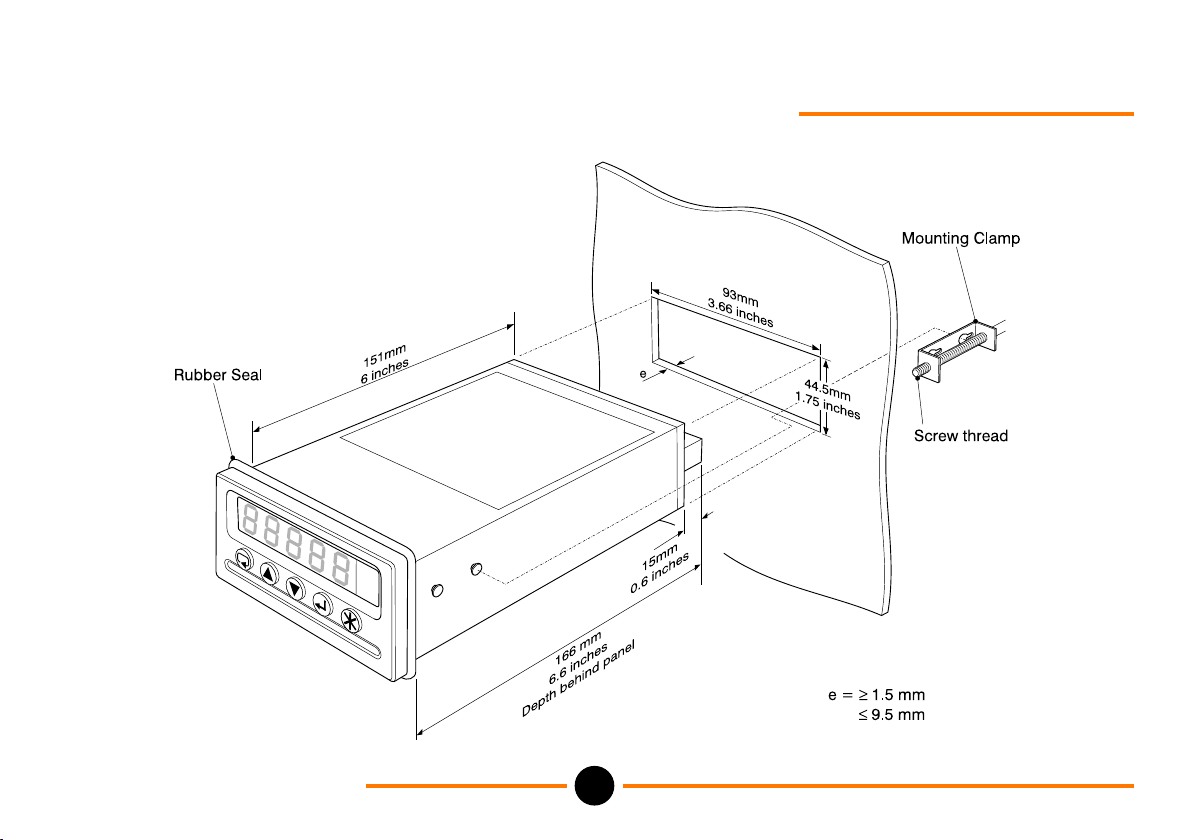
cabling (see section 4.2 for dimensions).
• Cut out the panel aperture to the dimensions shown.
• Slide the rubber seal over the unit, and push it
forward until it sits behind the front lip of the unit.
• Working from behind the panel, with the box fully
located, fit the side brackets to the studs and slide
them forward toward the panel until they lock into
place.
• Screw the brackets to the panel.
Caution
Do not overtighten the screws as this may
damage the case of the instrument.
4.0: Installation into a Panel
DPL53
4
M-3334 09/05
Page 7
4.0: Installation into a Panel (Continued)
4.2 Installation Dimensions
4.0: Installation into a Panel
DPL53
5
M-3334 09/05
Page 8
5.0: Using the Button Controls
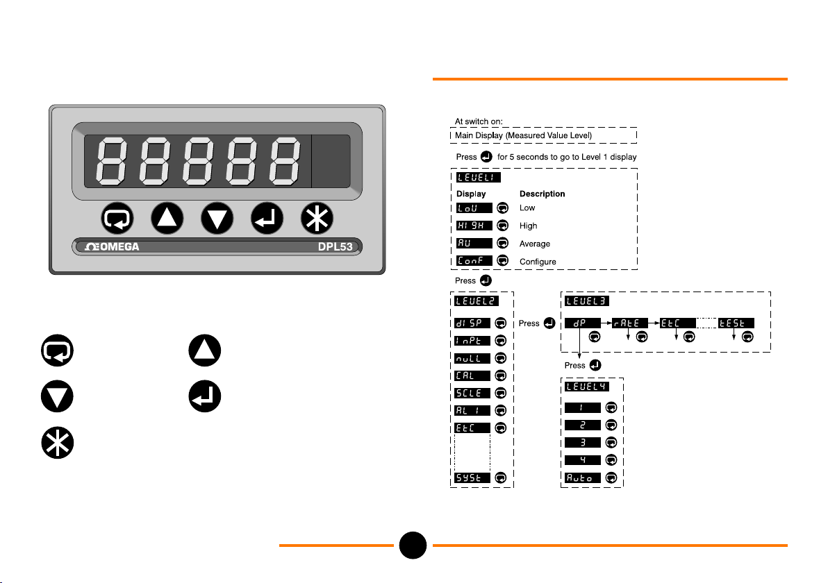
KEY TO BUTTONS:-
There are FOUR levels of button control
NEXT
DOWN
RESET
UP
ENTER
5.0: Using the Button Controls
DPL53
The complete chart showing all button indications is
shown in Appendix A.
6
M-3334 09/05
Page 9
6.0: Setup Options
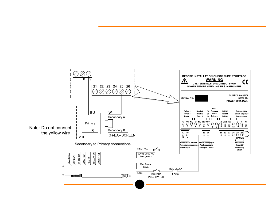
6.1 Transducer Connection to DPL53
The DPL53 works with the range LVDT transducers from
Omega. Below are the details on how to connect the
transducer to the DPL53
6.0: Setup Options
DPL53
7
M-3334 09/05
Page 10
6.0: Setup Options
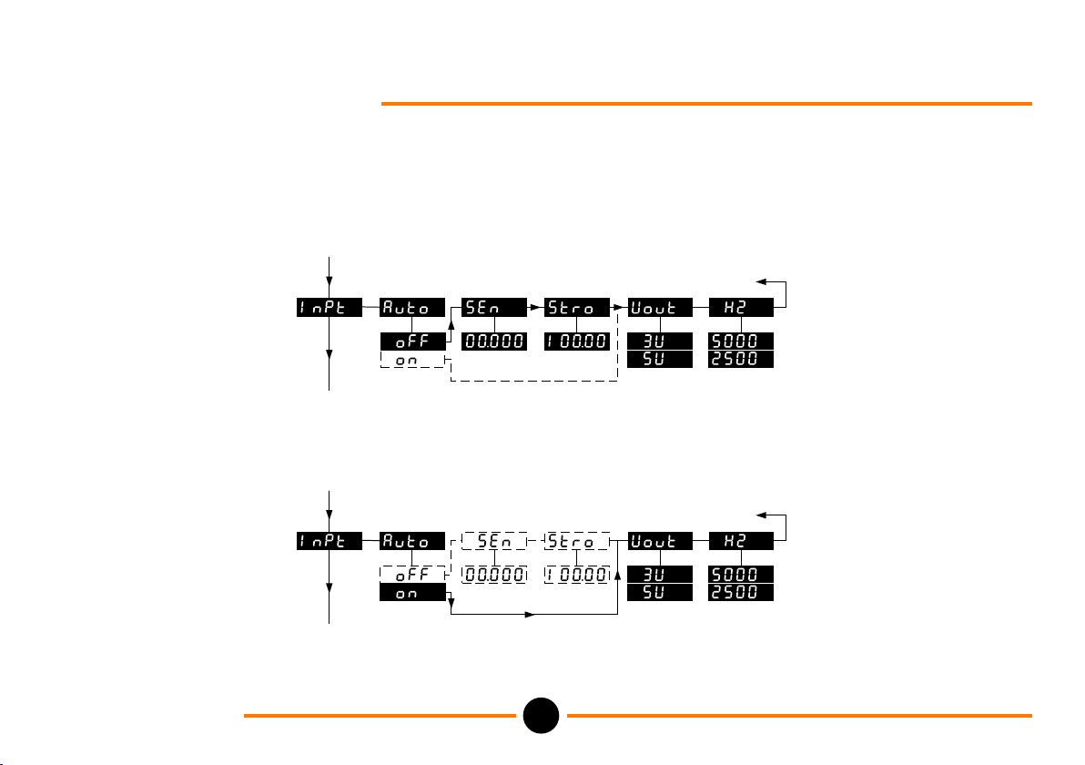
6.2 LVDT Sensitivity, Stroke Length, Excitation Voltage and Frequency
The process for LVDT sensitivity and stroke length depends on the availability of data.
A. If the sensitivity and stroke length are known (for example, supplied with the system on data sheets)
then the data is entered as shown in sub-menu A.
Sub-Menu A - If sensitivity and stroke length are known.
B. If the sensitivity and stroke length are unknown then the Auto-on option is selected as shown in sub-menu B.
6.0: Setup Options
DPL53
Sub-Menu B - If sensitivity and stroke length are unknown.
8
M-3334 09/05
Page 11
6.0: Setup Options
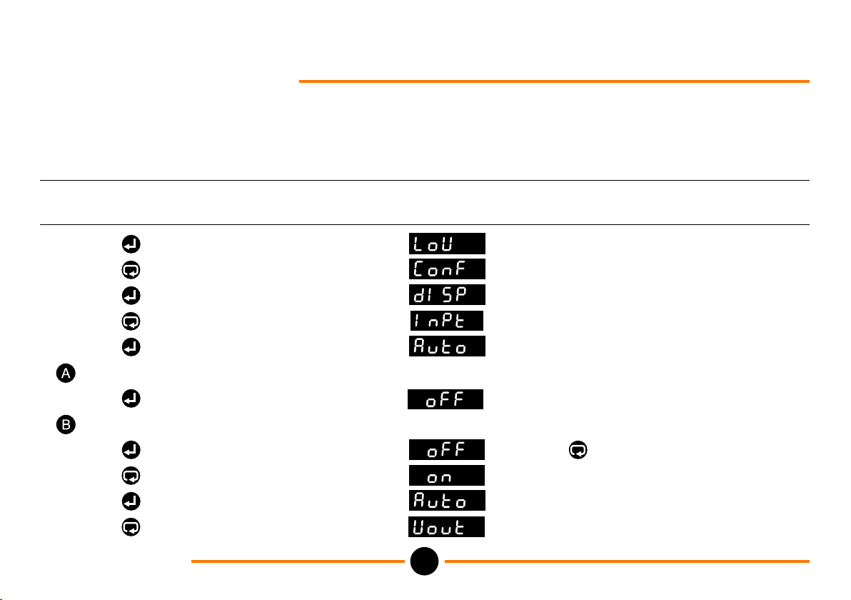
6.2 Setting the LVDT Sensitivity, Stroke Length, Excitation Voltage and Frequency
With reference to “Using the Button Controls” (section 5) and to the full menu in Appendix B, proceed to set the
sensitivity, stroke length, excitation voltage and frequency as follows:-
Action Button Action Display Additional Display
Number Information
1. Press and hold for 5 seconds
2. Press three times
3. Press and release
4. Press and release
5. Press and release
If the sensitivity and stroke length are known.
Press and release : Go to action number 6
If the sensitivity and stroke length are unknown
Press and release Note: Toggles
Press and release between On and OFF setting
6.0: Setup Options
Press and release
Press and release : Go to action number 18
9
M-3334 09/05DPL53
Page 12
6.0: Setup Options
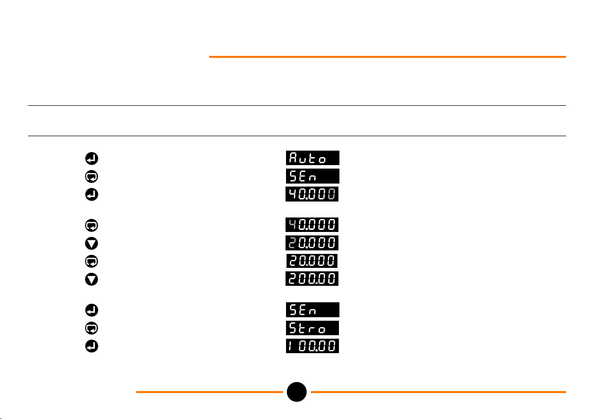
6.2 Setting the LVDT Sensitivity, Stroke Length, Excitation Voltage and Frequency cont’d
To change the setting to a different Sensitivity, (for example, a transducer, at 200 mV/V/mm).
Action Button Action Display Additional Display
Number Information
6. Press and release
7. Press and release
8. Press and release Example figure only
(with right hand figure flashing
9. Press and release four times moves flashing figure to the left
10. Press and release two times reduces flashing number from 4 to 2
11. Press and release once decimal point flashes
12. Press and release once moves the decimal point one place to the
right
13. Press and release once
14. Press and release
15. Press and release default stroke setting
16. Repeat actions 11 to 14 to input the transducer stroke length setting.
6.0: Setup Options
10
M-3334 09/05DPL53
Page 13
6.0: Setup Options
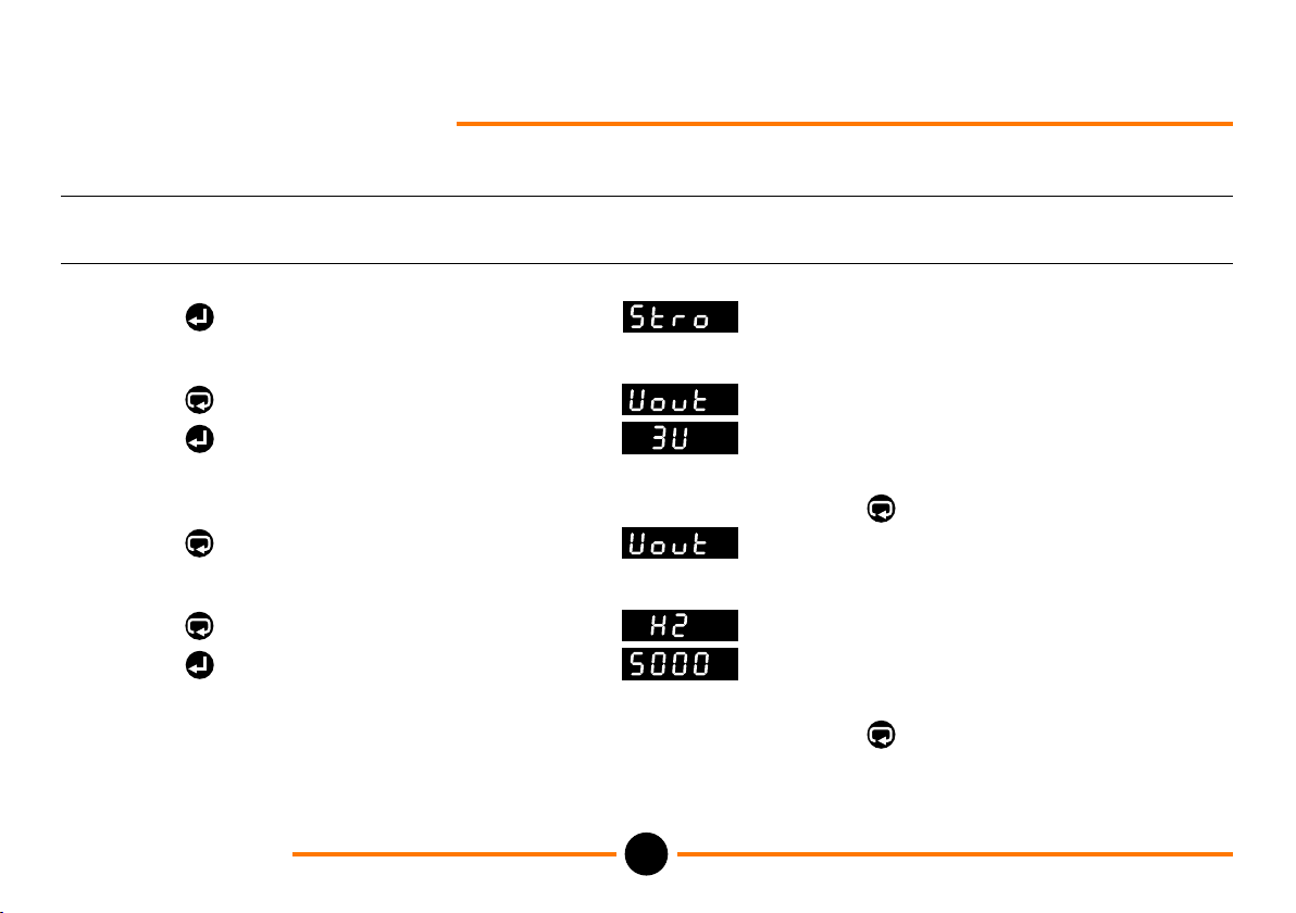
6.2 Setting the LVDT Sensitivity, Stroke Length, Excitation Voltage and Frequency cont’d
Action Button Action Display Additional Display
Number Information
17. Press and release
Excitation Voltage
18. Press and release
19. Press and release The two options are 3V AC and 5V AC
The default is 3V. To obtain 5V
press
20. Press and release
Excitation Frequency
21. Press and release
22. Press and release The two options are 2.5KHz and 5KHz
The default is 2.5KHz. To obtain 5KHz
press
6.0: Setup Options
11
M-3334 09/05DPL53
Page 14
6.0: Setup Options
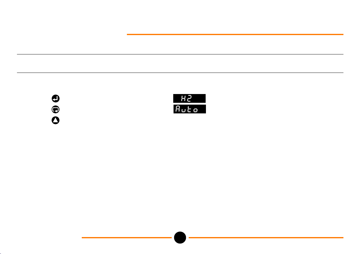
6.2 Setting the LVDT Sensitivity, Stroke Length, Excitation Voltage and Frequency cont’d
Action Button Action Display Additional Display
Number Information
Return to Level 1
23. Press and release
24. Press and release
25. Press and release three times Returns to main display
6.0: Setup Options
12
M-3334 09/05DPL53
Page 15
6.0: Setup Options
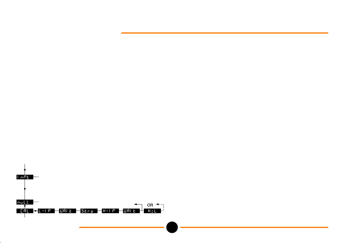
6.3 Calibration
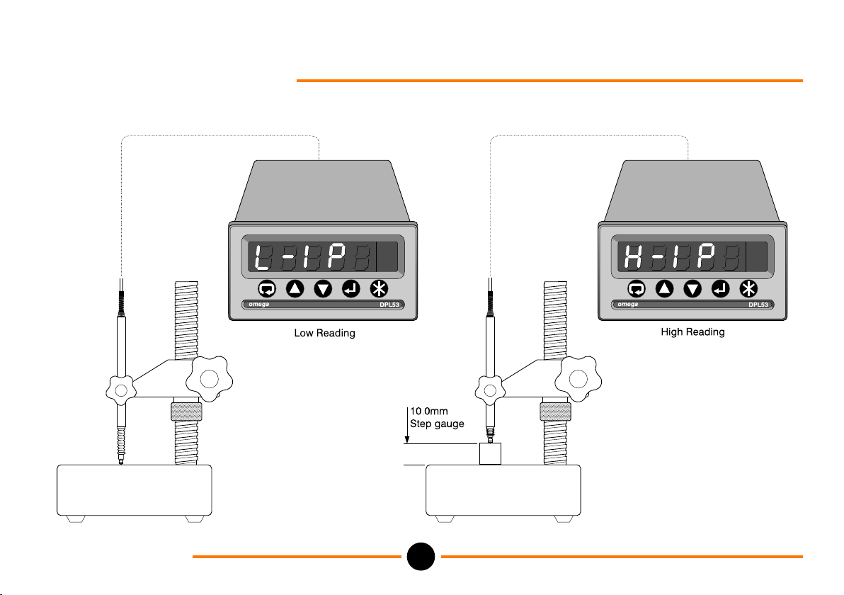
Calibration is the registering of the LVDT transducer
minimum and maximum displacement position into the
DPL53 display unit.
Before proceeding with the calibration, leave the power
on for 30 minutes.
The procedure given is for an example of a step gauge,
with low and high settings of 0.00 mm and 10.0 mm
respectively.
With reference to the Indicator Chart in Section 5 and
Appendix B, calibrate the LVDT transducer as in the
following table.
6.0: Setup Options
13
M-3334 09/05DPL53
Page 16
6.0: Setup Options
6.3 Calibration cont’d
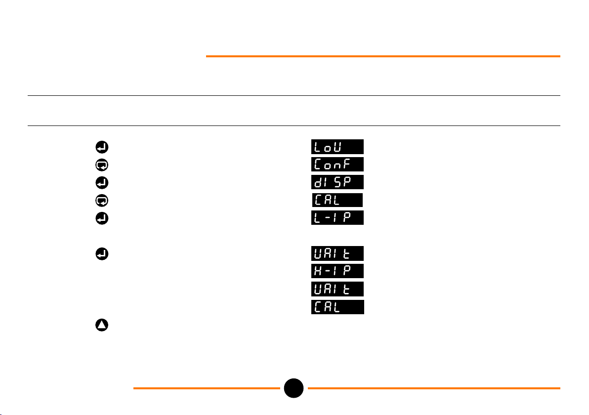
Action Button/ Action Display Additional Display
Number Step gauge Information
1. Press and hold for 5 seconds
2. Press three times
3. Press and release
4. Press and release 3 times
5. Press and release
6 Step gauge Set to zero (page 15)
7 Press and release for three seconds then
8 Step gauge Set to high point (eg; 10 mm) for three seconds then
(page 15)
9 Press and release twice returns to main display
6.0: Setup Options
DPL53
14
M-3334 09/05
Page 17
6.0: Setup Options
6.3 Calibration cont’d
6.0: Setup Options
DPL53
15
M-3334 09/05
Page 18
6.0: Setup Options
6.3 Calibration cont’d
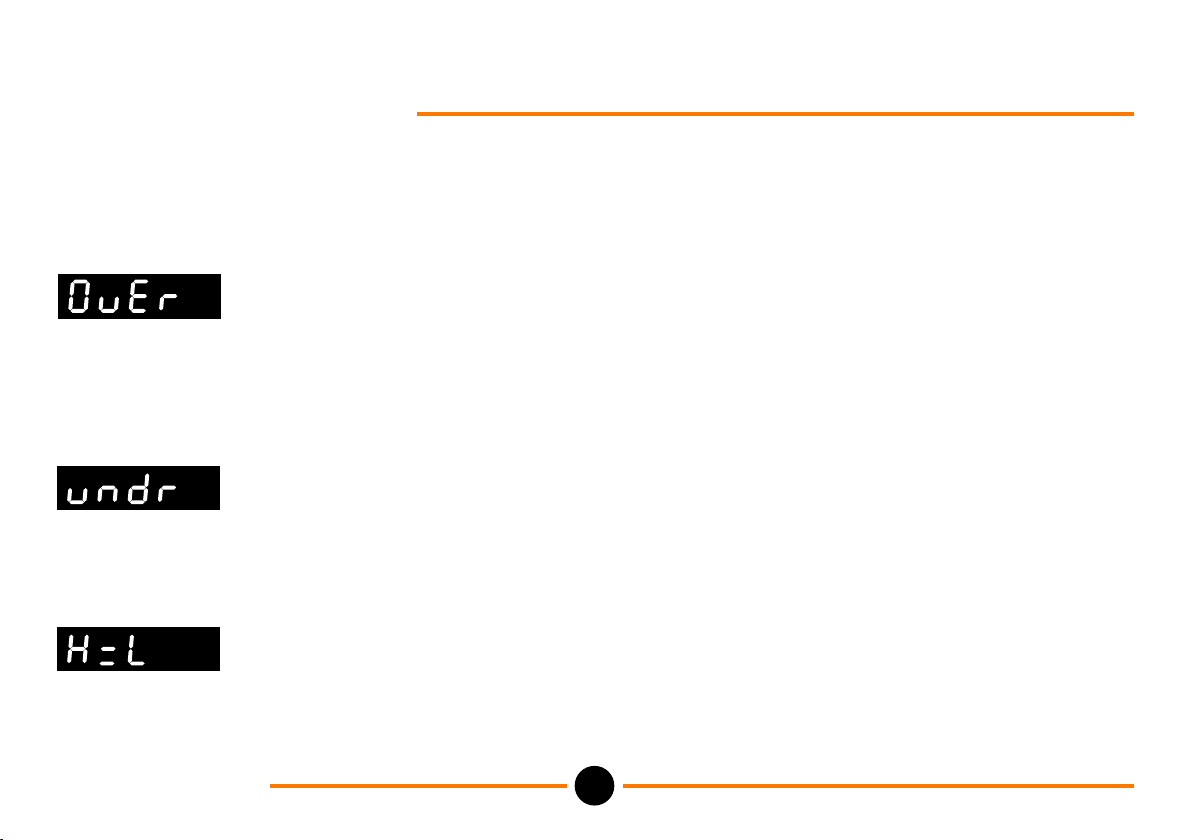
Calibration Error Codes
The instrument has detected an error
during calibration caused by the
output of the LVDT being greater than the maximum
positive input level of the instrument at the specified
sensitivity.
The instrument has detected an error
during calibration caused by the
output of the LVDT being lower than the specified
sensitivity.
The instrument measured the same
output from the LVDT at both
calibration points. (High = Low).
6.0: Setup Options
16
M-3334 09/05DPL53
Page 19
6.0: Setup Options
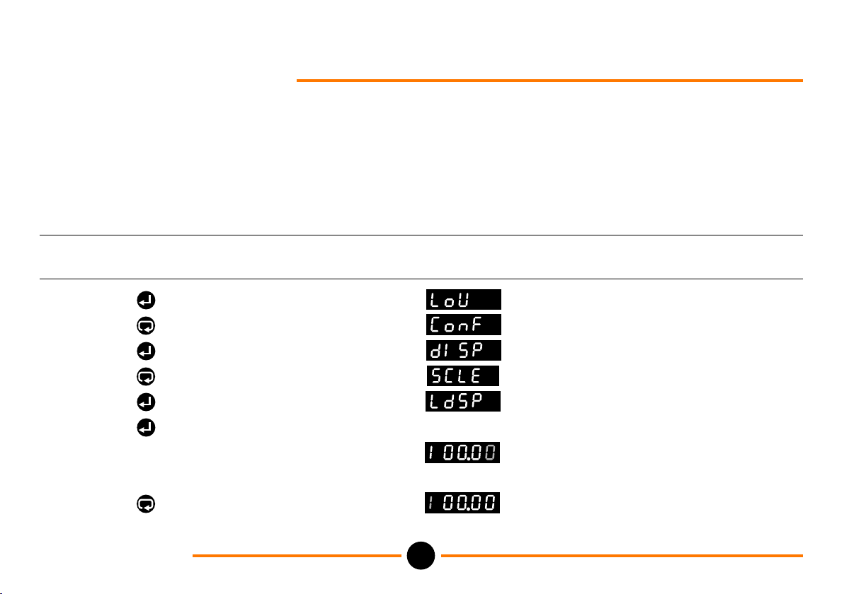
6.4 Scaling
Scaling is to set the display to show the correct
displacement for your LVDT, the LOW and HIGH display
values need to be defined. The procedure given is for
an example of scaling of between a minimum of 95 mm
and a maximum of 105 mm.
Action Button/ Action Display Additional Display
Number Micrometer Information
1 Press and hold for 5 seconds
2 Press three times
3 Press and release once
4 Press and release four times
5 Press and release once
6 Press and release once
assumed example with right hand number flashing
To set the lower figure (for example 95)
With reference to the Indicator Chart shown in Section 5
(Using Button Controls) and Appendix B, scale the
LVDT transducer as in the example table below:-
7 Press and release four times moves flashing number to the left
6.0: Setup Options
17
M-3334 09/05DPL53
Page 20
6.0: Setup Options
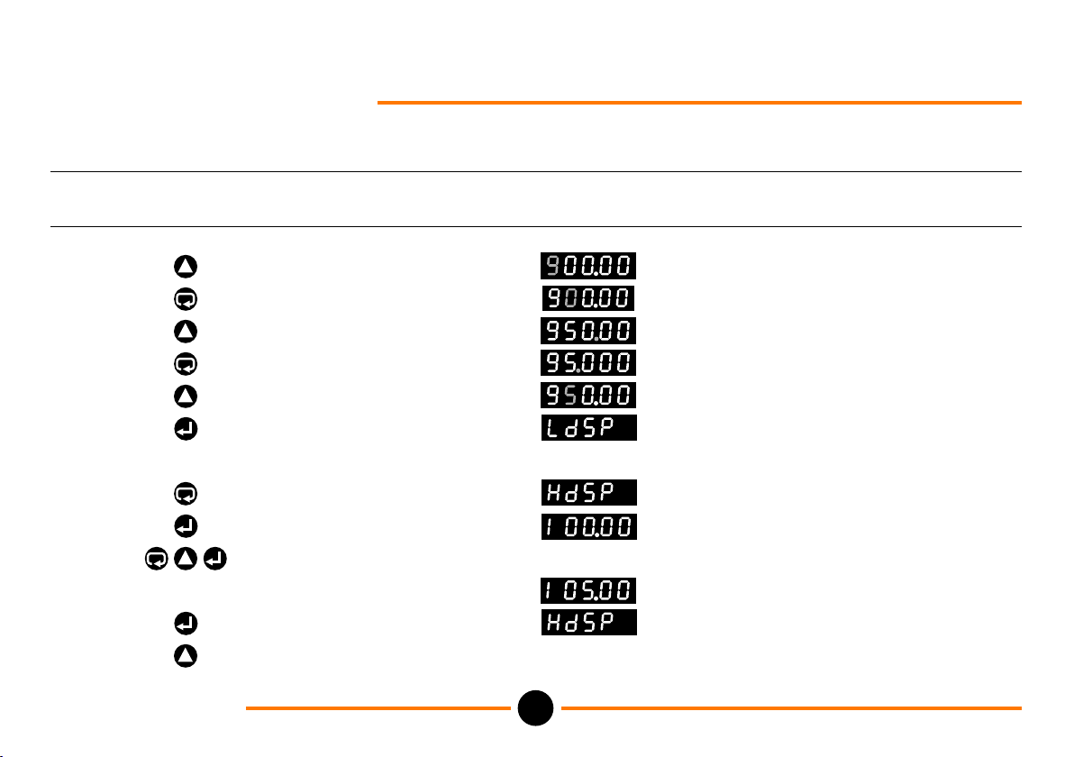
6.4 Scaling cont’d
Action Button/ Action Display Additional Display
Number Micrometer Information
8 Press and release eight times increases the flashing number from 1 to 9
9 Press and release four times moves flashing number to second left
10 Press and release five times increases flashing number from 0 to 5
11 Press and release ‘n’ times until decimal point flashes
12 Press and release once moves decimal point one place to the right
13 Press and release once
To set the upper figure (for example 105)
14 Press and release once
15 Press and release once
16 Press the buttons in a similar
manner to actions 7 to 13 to obtain
17 Press and release once
18 Press and release 3 times returns to main display
6.0: Setup Options
18
M-3334 09/05DPL53
Page 21
7.0: Description of the DPL53 Functions
This chapter describes the functions which the DPL53 can carry out. Each section is headed with Level 2 menu option
(Refer to 5.0 Using the Button Controls).
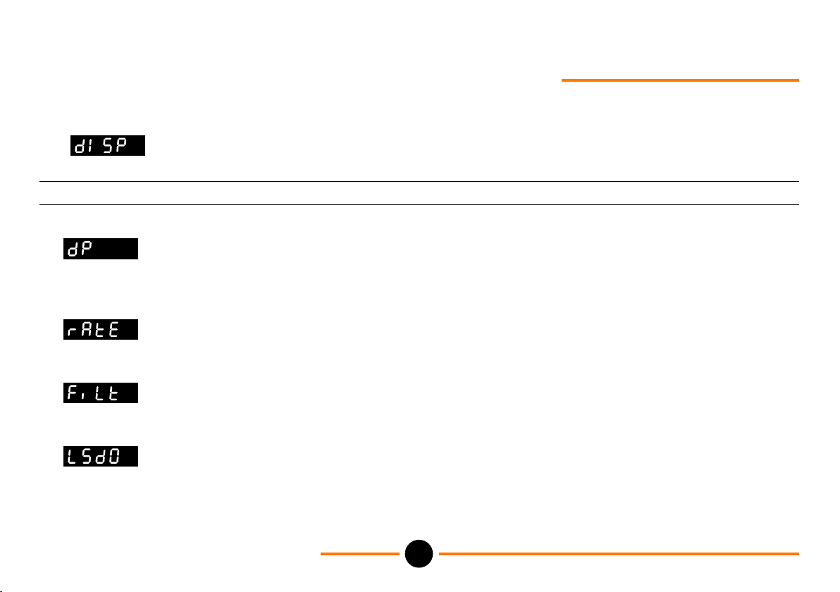
7.1 Configuring the Display
Display Function
Decimal Point Position
Display Update Rate
Display Filtering
Least Significant Digit Zero
7.0 Description of DPL53 Functions
DPL53
Description
Allows the position of the decimal point to be fixed or
auto ranging. The decimal point may be fixed to give 0,
1, 2, 3 or 4 digits after the decimal point. The default is
1 decimal point.
Allows the update rate of the display to be set from
every 0.1 seconds to 0.5 seconds. The options are 2, 4
or 10Hz, the default setting is 2Hz.
Used to set up filtering of displayed values. The time
constant of the filter entered in seconds. The default
value is zero (no display filtering).
When set to ON the right hand digit only displays zero
during normal running. The default is OFF.
19
M-3334 09/05
Page 22
7.0: Description of the DPL53 Functions
7.1 Configuring the Display. cont’d
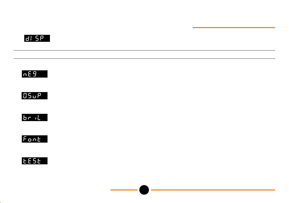
Display Function
Display Negative Numbers
Leading Zero Suppression
Brilliance
Font
Test
7.0 Description of DPL53 Functions
DPL53
Description
Allows the display of negative numbers to be enabled
(ON) or disabled (OFF). The default setting is negative
numbers ON.
Allows leading zeros to be displayed. When ON the
leading zeros are not displayed. The default is ON.
Allows the brightness of the display to be adjusted in
the range 1 to 4. The default setting is 4 (highest
intensity setting).
One of two fonts for the display of numerals may be
selected to allow compatibility with some older
instruments. The default font is 1.
Performs a display test which illuminates all display
digits and segments (8.8.8.8.8.) when the enter button
is pressed.
20
M-3334 09/05
Page 23
7.0: Description of the DPL53 Functions
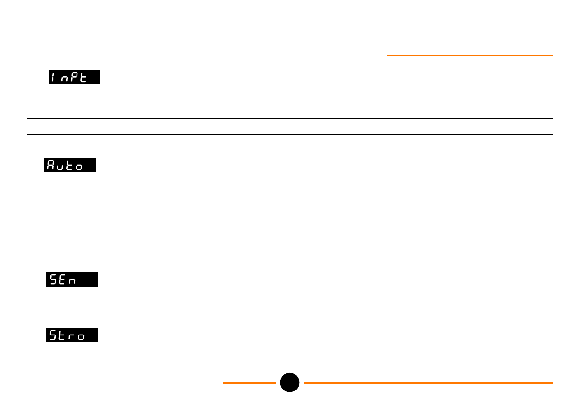
7.2 LVDT Configuration
Before any calibration or scaling operations are performed some operating parameters related to the use of the
particular LVDT need to be set. These parameters are all set up from the input menu
Display Function
Automatic Gain Selection
Sensitivity
Stroke
7.0 Description of DPL53 Functions
Description
Allows the instrument to set its gain automatically by
determining the sensitivity of the attached LVDT during
Calibration. The options are Automatic Gain Selection
Enabled (ON) or disabled (OFF), this is the default
state.
Note: When the AUTO option is set to ON. The sesitivity
and stroke options will not be accessible.
Value is entered to allow the gain of the measurement
input of the instrument to be determined from the
specified sensitivity of the LVDT. Details of the
sensitivity of your LVDT should be in the documentation
supplied.
Allows the stroke of the LVDT to be entered as a value
directly in mm. In order to determine the appropriate
gain setting. The default stroke setting is 100.0mm.
21
M-3334 09/05DPL53
Page 24
7.0: Description of the DPL53 Functions
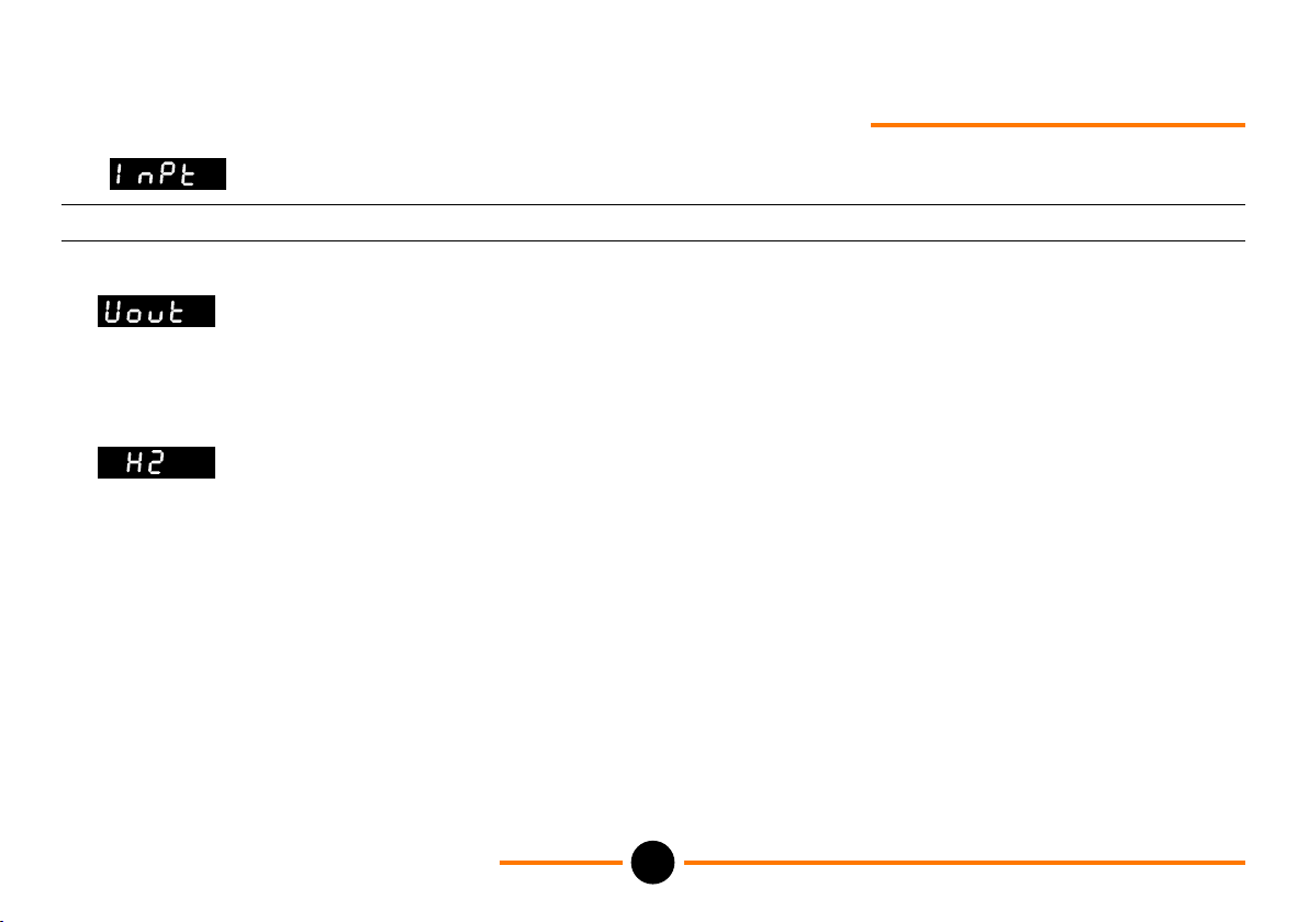
7.2 LVDT Configuration cont’d
Display Function
Excitation Voltage
Excitation Frequency
Description
Selects the correct output voltage for excitation for the
LVDT. The appropriate voltage to use will be specified
in the LVDT documentation. There are two options 3V
AC and 5V AC (rms.), the default setting is 3V.
Sets the correct excitation frequency as specified in the
LVDT documentation. The options are 2.5KHz or 5KHz.
The default is 2.5KHz.
7.0 Description of DPL53 Functions
22
M-3334 09/05DPL53
Page 25
7.0: Description of the DPL53 Functions
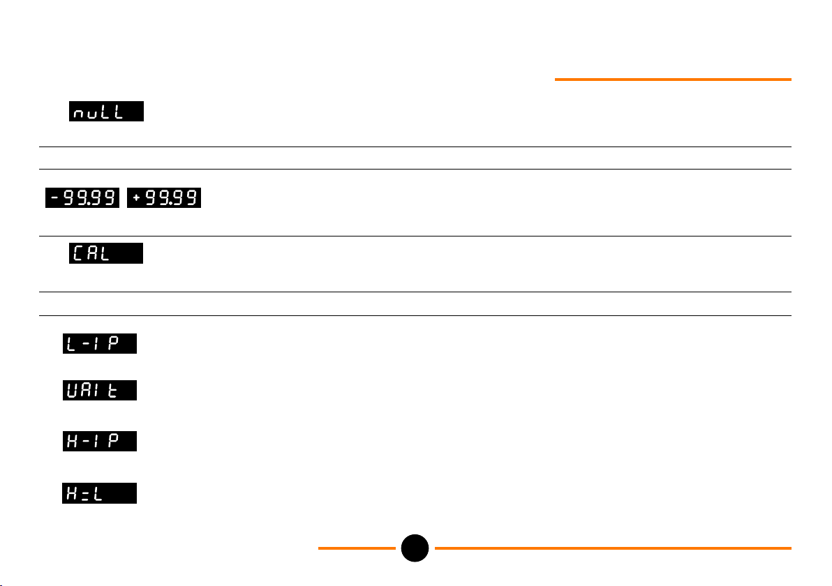
7.3 Null Position
This function allows the user to locate the midpoint of the LVDT’s measurement range (Null Point).
Display Function
Null Position
7.4 Calibration
This menu option is described in more detail in Section 6.3 Calibration.
Display Function
Low Input
Wait
High Input
High=Low
7.0 Description of DPL53 Functions
Description
The value will be displayed ‘FLASHING’. The closer the
value to zero, the nearer the LVDT is to its ‘NULL
POSITION’.
Description
Allows unit to calibrate to the minimum displacement
position of the LVDT.
While the low and high input positions are being
calibrated, ‘wait’ is displayed.
When wait elapses ‘high input’ is displayed and the
LVDT is set to its maximum displacement position.
The instrument measured the same output from the
LVDT at both calibration points.
23
M-3334 09/05DPL53
Page 26
7.0: Description of the DPL53 Functions
7.5 Scaling Option
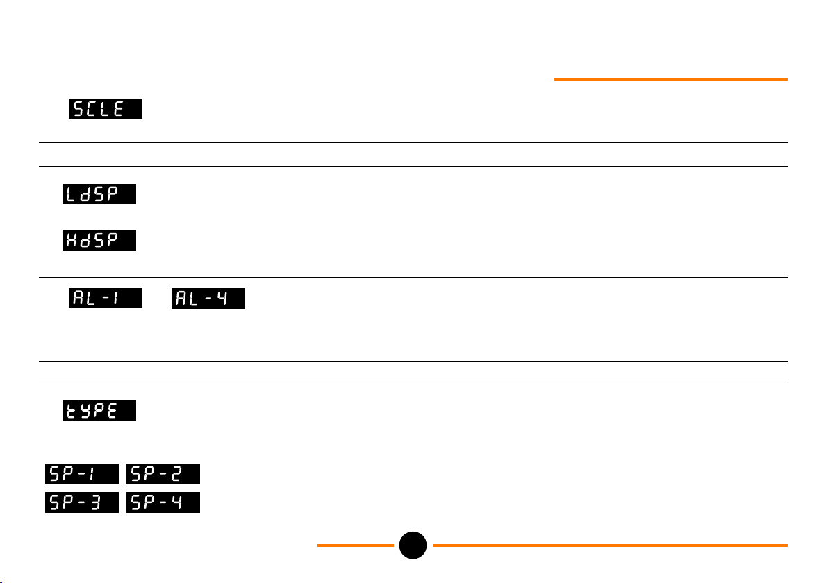
This menu option is described in more detail in Section 6.4 Scaling.
Display Function
Description
Low (Zero) Display
High Scale Display
7.6 to Configuring Alarms
There are four Alarms; each can be configured separately. All Alarms default to OFF. Note 1: Only relay outputs can be
activated by the Alarms. Note 2: The alarms are not affected by the analogue output.
Display Function
Alarm Type
Setpoint
7.0 Description of DPL53 Functions
DPL53
The minimum displacement display which corresponds
to the Low calibration point ( L - i P). Default is zero.
The maximum displacement display which corresponds
to the High calibration point ( H - i P ). Default is 100.0.
Description
Options are none (OFF), high, low and deviation. Alarm
1 and 3 default to high and Alarm 2 and 4 default to low.
There are four setpoints, one for each of the four
alarms. Each set point may be set to any value within
the display range of the instrument i.e. -19999 to 99999.
The default setpoints are 99999 for Alarm 1 and Alarm 3
and -19999 for Alarm 2 and Alarm 4.
24
M-3334 09/05
Page 27
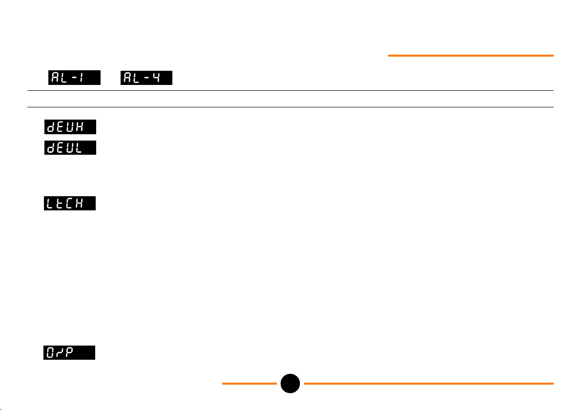
7.0: Description of the DPL53 Functions
7.6 to cont’d
Display Function
Deviation Setpoints
Latching
Output
7.0 Description of DPL53 Functions
DPL53
Description
This allows the difference between the alarm setpoint
and the high and low deviation levels to be defined. The
default setting for both is zero. These menu options are
only displayed (and valid) when the alarm type is set to
deviation.
All alarms may be set to latched (ON) or non-latched
(OFF). When alarms are set to latched then the alarm
indication and any associated output will remain in the
active state even when the alarm condition has cleared.
Latched alarms must be acknowledged to clear
indications and outputs to their inactive (non-alarms)
states. To acknowledge an alarm; either press the UP
and DOWN arrow keys together or configure one of the
two status inputs as an alarm acknowledge (ACK). The
default setting is OFF (non-latching). The alarm
condition must be cleared before the alarm can be
acknowledged.
Allows you to specify which output is activated when the
alarm condition is valid. The dual relay options are OP1 (Relay 1) or OP-2 (Relay 2).
25
M-3334 09/05
Page 28
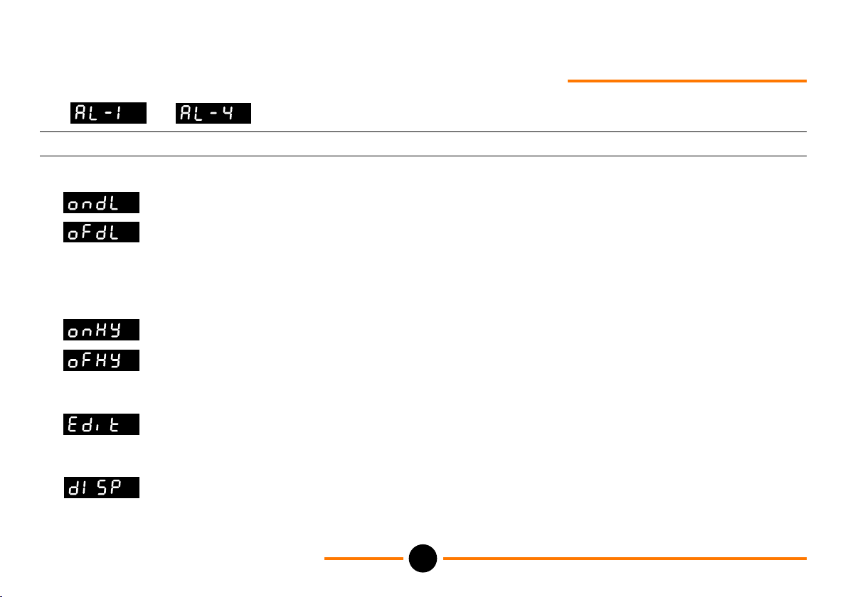
7.0: Description of the DPL53 Functions
7.6 to cont’d
Display Function
Delay
Hysteresis
Front Panel Edit
Message Display
7.0 Description of DPL53 Functions
DPL53
Description
Allow the on and off delay times for each of the alarms
to be defined. The on delay defines the time that the
alarm condition must be present before the alarm is
activated. The off delay defines the time, that the alarm
condition is cleared before the alarm is deactivated.
The default setting for both the on and off delay is zero.
Define the difference between the set point and the
point at which the alarm is activated or deactivated.
The on and off Hysteresis may be specified separately
above and below the setpoint.
When this facility is ON the operator may access the
alarm setpoints from the front panel by pressing the
DOWN arrow key and without having to enter the
configuration menus. The default is ON.
This parameter allows you to define whether alarm
messages are displayed (ON) or not (OFF). The default
setting is ON.
26
M-3334 09/05
Page 29
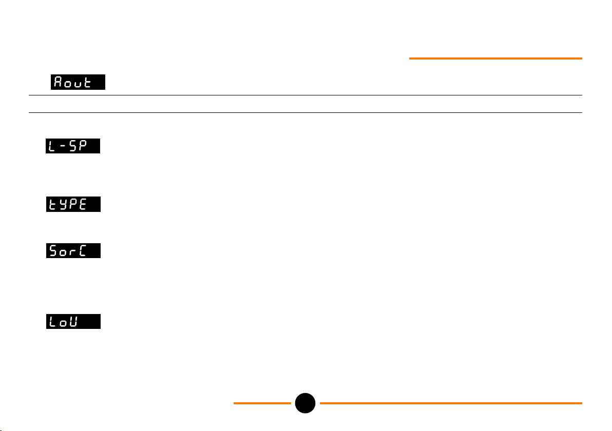
7.0: Description of the DPL53 Functions
7.7 Analogue Output
Display Function
Linked Setpoints
(Alarm menu 3 and 4 only)
Output Type
Signal Source
Low Scaling Point
7.0 Description of DPL53 Functions
DPL53
Description
This allows you to link setpoint 3 to setpoint 1, and
setpoint 4 to setpoint 2. When setpoints are linked,
setpoint 1 will automatically change to setpoint 3 values.
Changing setpoint 2 will change setpoint 4. The default
is OFF (No setpoint linking).
Allows the output to be set to 0-10V, 0-20mA or 4-20mA.
The default setting is 4-20mA.
Defines the source of the values to be output. The
source can be selected from the display value (inPt),
maximum or peak value (High), minimum value (LOU),
average value (Av) or a value received from the
communications interface (Conn). The default is inPt.
Defines the display value at which the output will reach
its minimum level ie: 4mA (4-20mA), 0mA (0-20mA) or
0V (0-10V) dependent on analogue output type selected
above. The default value is 0%.
27
M-3334 09/05
Page 30
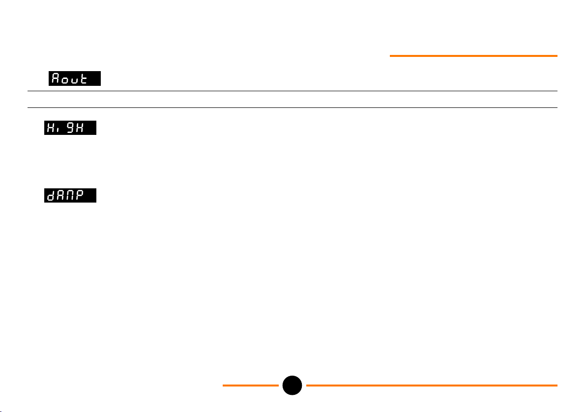
7.0: Description of the DPL53 Functions
7.7 Analogue Output cont’d
Display Function
High Scaling Point
Damping
7.0 Description of DPL53 Functions
DPL53
Description
Defines the display value at which the output will reach
its maximum level ie: 20mA (0 or 4-20mA) or 10V (010V) dependent on analogue output type selected
above. The default value is 100%.
Output damping defines the time constant in seconds
for damping the output. This parameter is used to limit
the rate of change of the output and may be adjusted in
the range 0 to 999 seconds. The default is 0.
28
M-3334 09/05
Page 31
7.0: Description of the DPL53 Functions
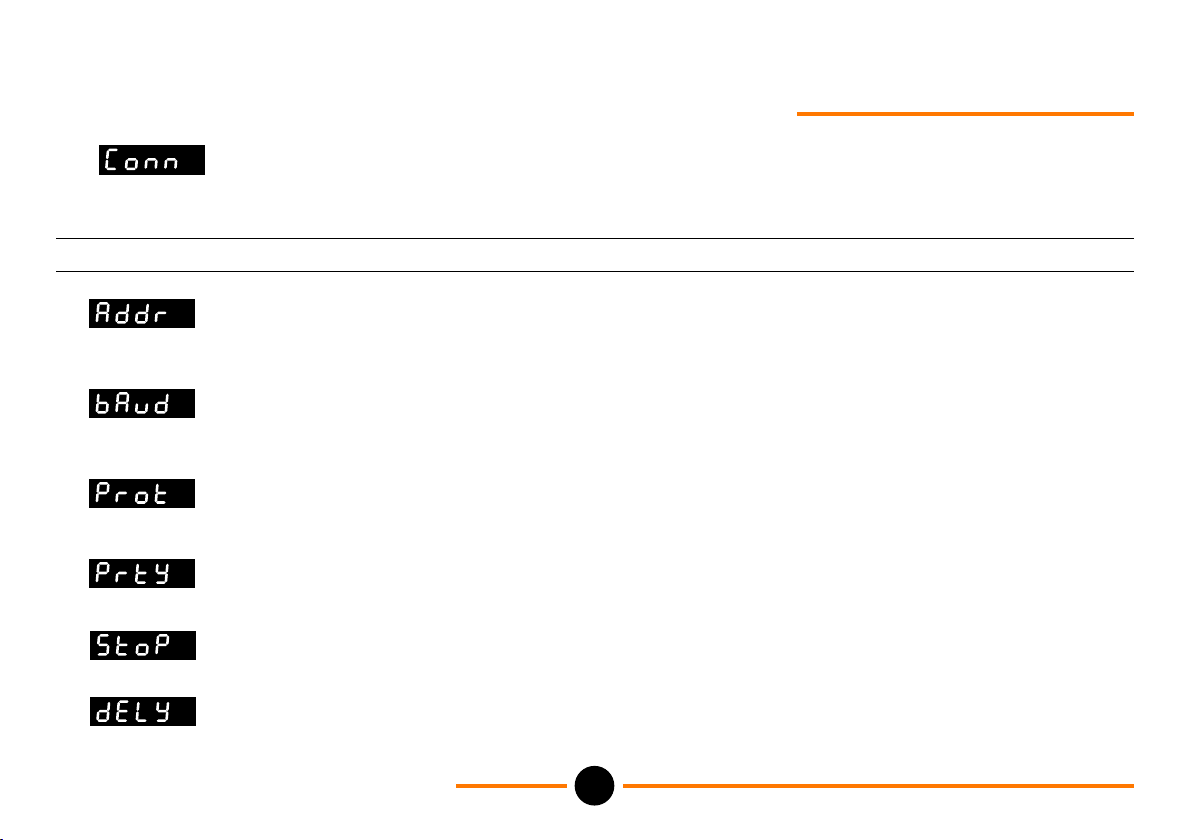
7.8 Configuring Serial Communications
The DPL53 can communicate with a master device via an RS232 interface. For more detailed information refer to 8.0
RS 232 Communication.
Display Function
Instrument Address
Baud Rate
Protection
Parity
Stop Bits
Transmit Delay
7.0 Description of DPL53 Functions
DPL53
Description
Defines the instrument address when using the
instrument in a multidrop system. The range of valid
addresses is 1 - 247. The default is 1.
Allows the baud rate to be selected. The options are
1200, 2400, 4800 and 9600. The default is 9600.
Allows the instrument parameter settings to be
protected against change from the serial interface (write
protection ON). The default is OFF.
Defines parity for all communications. The options are
even, odd or no parity. The default is Even.
Defines the number of stop bits, 1 or 2.
The default is 1.
Add a delay, in milliseconds, before the DPL53
responds to any received commands.
29
M-3334 09/05
Page 32
7.0: Description of the DPL53 Functions
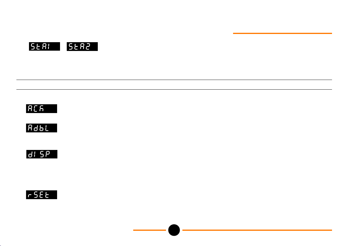
7.9 Status Logic Inputs
The DPL53 provides two status (logic) inputs which can be assigned to perform one or more functions when activated.
All functions are started when there is a low on the status input i.e. placing a short across the input (from a switch or
relay). The calibration function is started when there is a transition from in-active to active state on the input.
Display Function
Alarm Acknowledge
Alarm Disable
Displays
Reset
7.0 Description of DPL53 Functions
DPL53
Description
Clears all latched alarms which are no longer in an
alarm condition. The default is OFF.
Disables all alarms when the status inputs is active.
The default is OFF.
Allows any one of the following to be displayed whilst
the status input is active: Lamp test, the average, low
or high values, or display hold. When the status input is
inactive the normal measured value is displayed. The
default for this is NONE.
This resets the High (peak), Low (minimum) and
Average values to the current measured value. The
default for this option is OFF.
30
M-3334 09/05
Page 33
7.0: Description of the DPL53 Functions
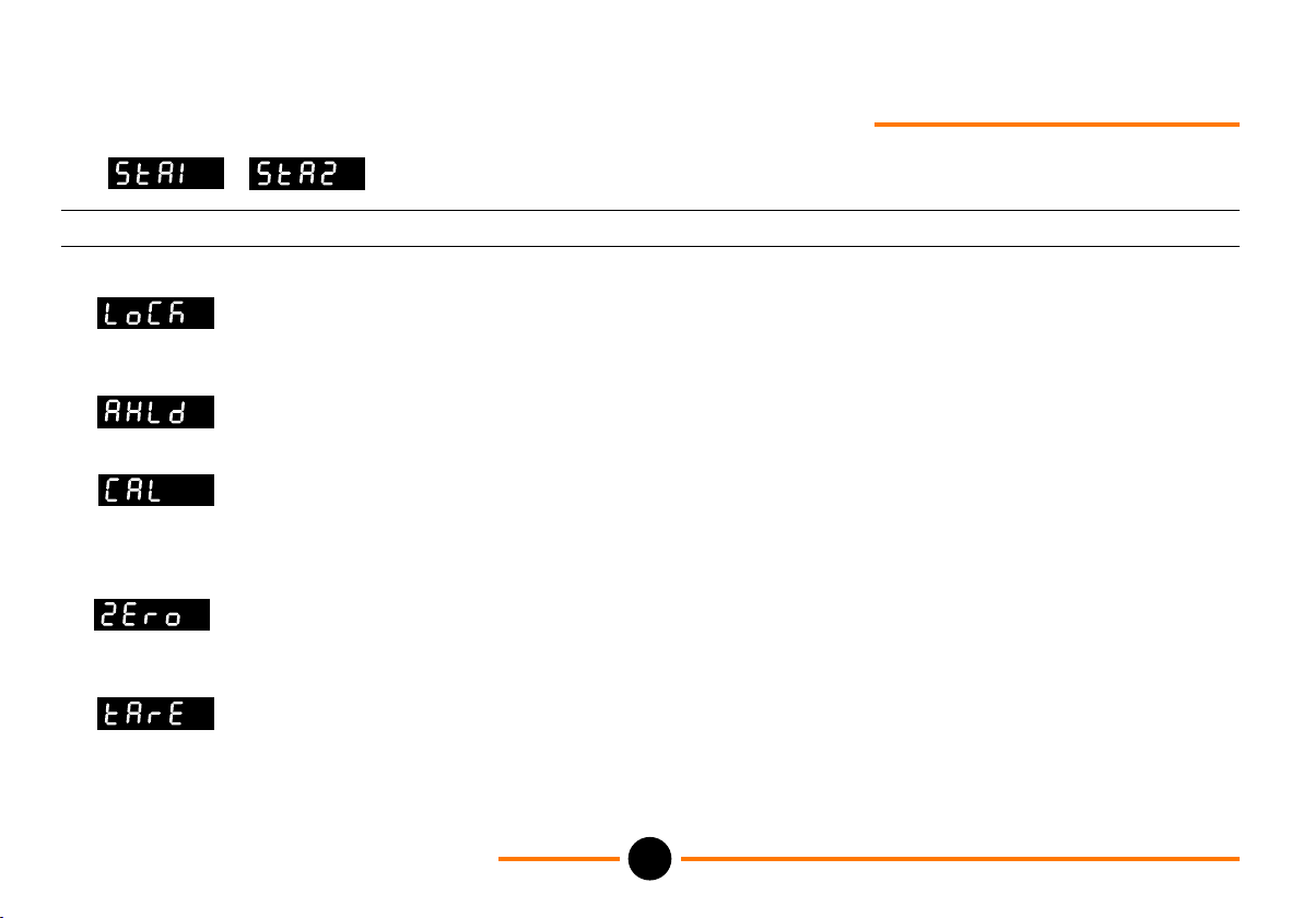
7.9 Status Logic Inputs cont’d
Display Function
Front Panel Keypad Disable
Analogue Output Hold
Auto Fast Calibration
Zeroing
Tare
7.0 Description of DPL53 Functions
DPL53
Description
Disables the front panel keys, the default state is OFF.
This allows the analogue output to be held at a (Frozen)
level. The default state is OFF.
This is used to initiate the automatic calibration process.
The process is started when the status input is
activated. The default for this option is OFF.
This sets the measured and displayed values to Zero
(0.000) permanently (or until the instrument is
defaulted), removing any offset errors from the system.
This tares the measured value subtracting a fixed
amount from all subsequent measurements. The
default is ON.
31
M-3334 09/05
Page 34
7.0: Description of the DPL53 Functions
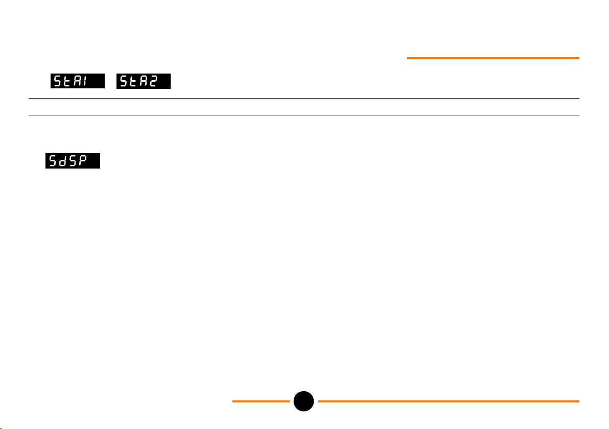
7.9 Status Logic Inputs cont’d
Display Function
Status Message Display
7.0 Description of DPL53 Functions
DPL53
Description
This enables or disables the display of messages
related to the status input function. When ON
messages are displayed alternately with value being
displayed ie: if the unit is displaying the high value, then
the high value is displayed flashing with the message
‘HiGH’. This indicates to the user that the current input
value was not being displayed. The default is ON.
32
M-3334 09/05
Page 35
7.0: Description of the DPL53 Functions
7.10 Configuring Function Keys
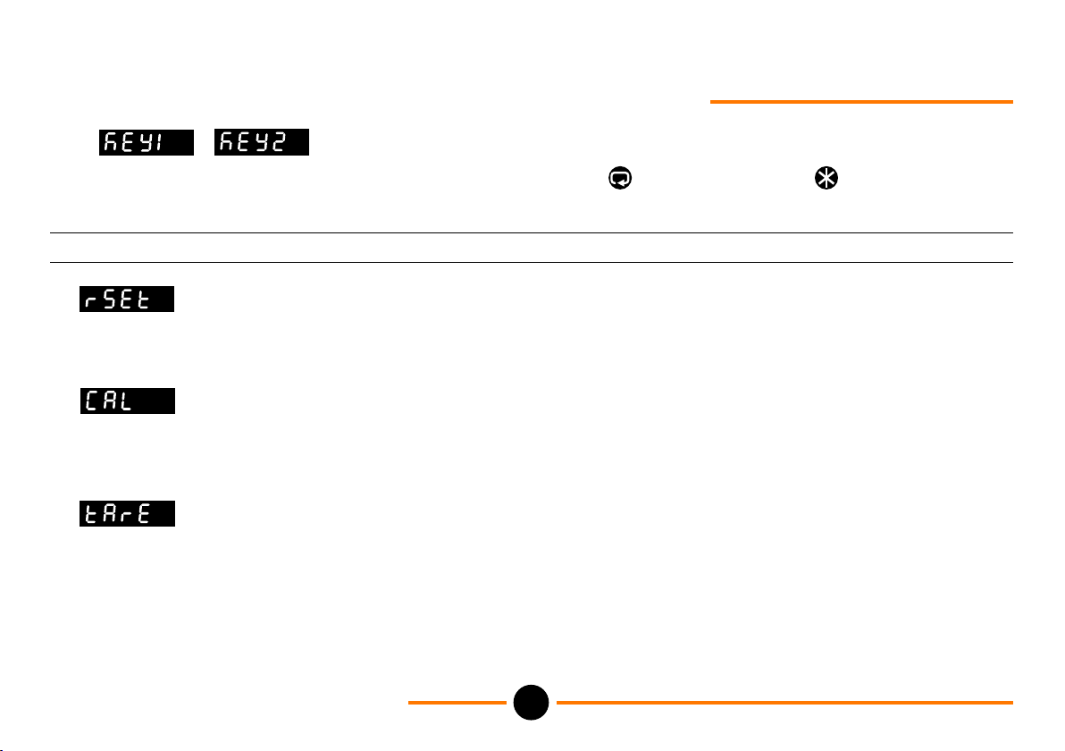
There are 2 function keys which can be configured. Function Key 1 and Function Key 2 . The following
functions may be assigned to either or both keys unless stated.
Display Function
Reset
Auto Fast Calibration
Tare
7.0 Description of DPL53 Functions
DPL53
Description
If ON, the function button will reset the High (Maximum),
Low (minimum) and Average values to the current
measured value. The default is OFF.
When ON then the function key 1 or 2 will initiate the
automatic calibration process. When pressed the
display will flash the message ‘CAL’. The key must be
pressed again whilst the display is flashing to perform
the function. The default state is OFF.
Tares the measured value, subtracting a fixed amount
from all subsequent measurements. The value
subtracted is the current value when the key is pressed.
When the function is assigned to a function key,
pressing the key once will activate the tare (relative
displacement) measurement. Pressing the key again
while tare is active will deactivate the function. Default
is ON.
33
M-3334 09/05
Page 36
7.0: Description of the DPL53 Functions
7.10 Configuring Function Keys cont’d
Display Function
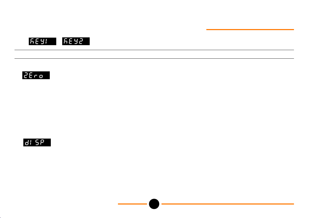
Zeroing
Displays
7.0 Description of DPL53 Functions
DPL53
Description
This sets the measured and displayed values to Zero
(0.000) permanently (or until the instrument is defaulted
or calibrated), removing any offset errors from the
system. When assigned to a function key pressing the
key once will cause the DPL53 to display ‘ZEro’
flashing. To perform the ‘Zero’ the function key must
be pressed again, to confirm the operation, (the display
will flash for approximately 5 seconds). Once
confirmed, the ‘Zero’ will be performed immediately.
The default is OFF.
Allows any one of the following to be displayed whilst
the Function key is pressed: Lamp test, the average,
low or high values, or display hold. When the key is
released normal display is returned. The default is
NONE (no display function).
34
M-3334 09/05
Page 37
7.0: Description of the DPL53 Functions
7.11 System Options
Display Function
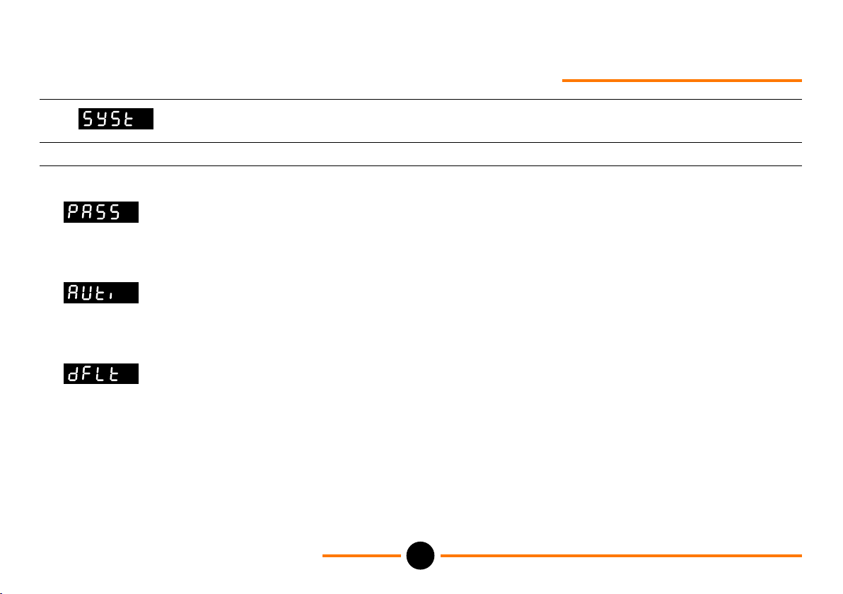
Password
Averaging Time
Default
7.0 Description of DPL53 Functions
DPL53
Description
Enter any value between 1 and 99999. When enabled
the configuration menu cannot be accessed without first
entering the password number. The default value is 0.
(No Password).
This average value is not a true arithmetic average. The
default is 1 (second).
Allows the unit to reset back to its factory default
settings. Select ON to default the instrument. It will
automatically revert to OFF when the instrument is
defaulted.
35
M-3334 09/05
Page 38
7.0: Description of the DPL53 Functions
7.11 System Options cont’d
Display Function
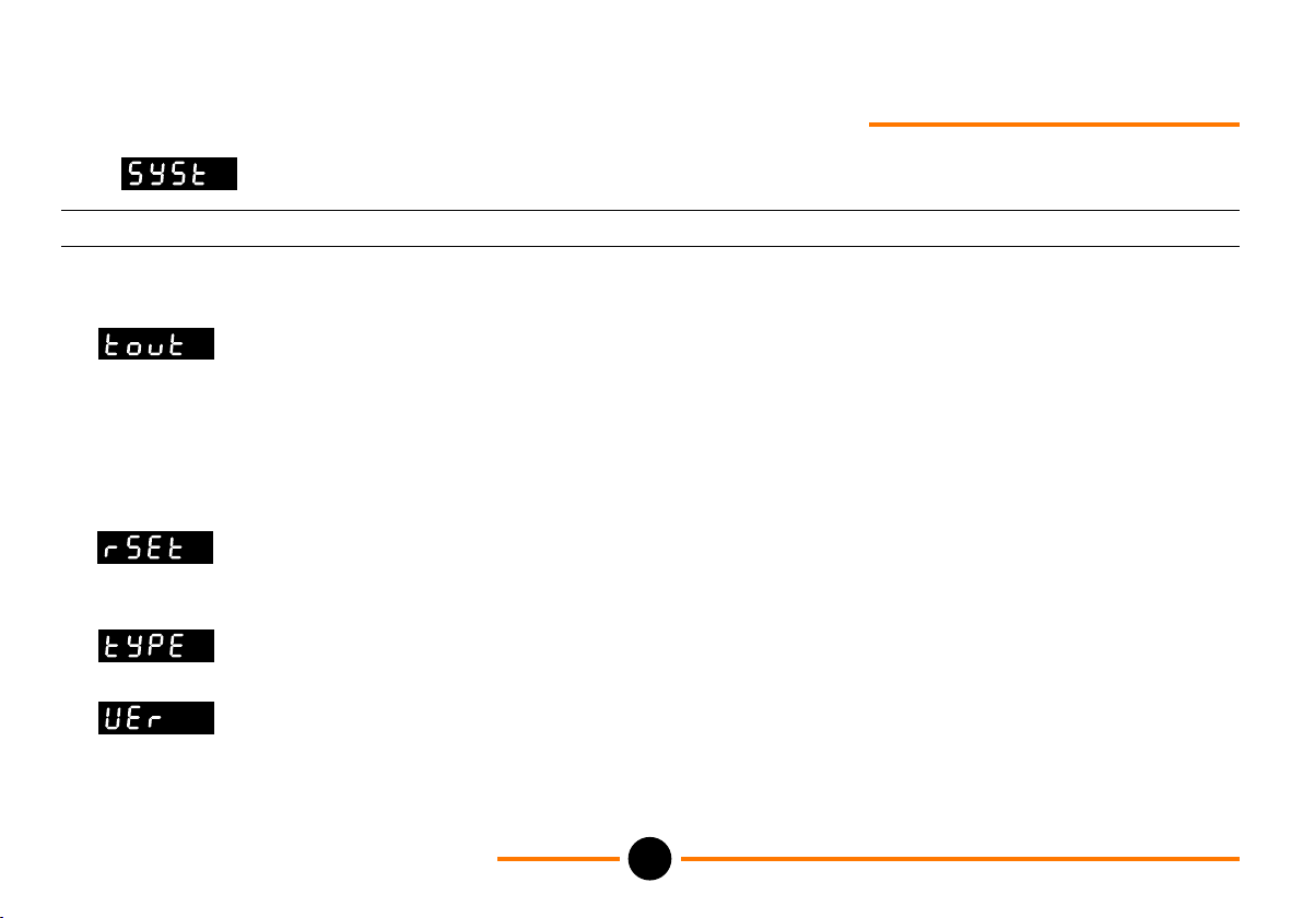
Time-out
Reset
Type
Version
7.0 Description of DPL53 Functions
DPL53
Description
This defines the time that the unit will remain in
configuration mode when there is no key activity. If
there are no key presses within the specified time
period the unit will return to normal operation. the
default time-out is 60 seconds and is adjustable
between 30 to 300 seconds. This is disabled during the
Calibration sequence.
Allows the unit to be reset. The reset process, when
activated, will display Wait and start the sequence. The
unit will reset back to its factory default settings, and go
through the power-up sequence.
Shows the type of readout ie: DPL53.
Shows the version of the DPL53.
36
M-3334 09/05
Page 39
8.0: RS232 Communications with DPL53
8.1 Overview
This language has been developed for communication
between the DPL53 and the master device via an RS232
communications interface. The master device could be
a computer, which would be able to read from and write
to, memory locations within the DPL53.
There are two types of memory locations, analogue and
logic. Analogue memory locations can be set to any
value within a specified range. Logic locations can be
set to either ON or OFF. A full list of the memory
location within the DPL53 are listed in Appendix D.
Memory Locations.
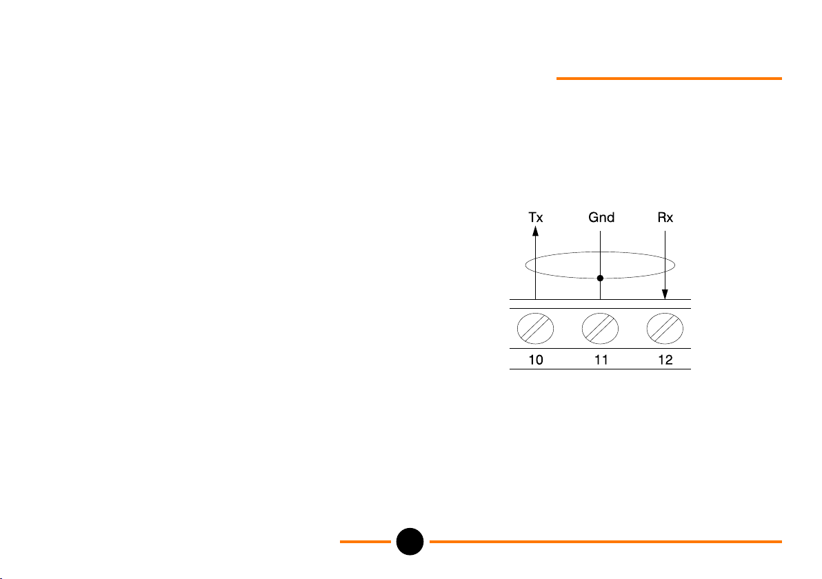
8.2 DPL53 Connections to RS232 communication
The connections required to interface the DPL53 to a
RS232 interface are shown below.
RS232 connection to a Master device (Computer).
8.0: R232 Communications with DPL53
37
M-3334 09/05DPL53
Page 40

8.0: RS232 Communications with DPL53
A screened twisted pair cable should be used for all
applications requiring cable lengths greater than 3m.
The screen of the cable should be connected to the
Frame Ground or Ground connection of the Master
device.
Several DPL53's can be connected to a computer, each
DPL53 with its own identification number.
8.3 DPL53 Settings for RS232 communication
The default setting for the DPL53 are as follows:
Parameter Default Settings
Communications Address 1
Baud Rate 9600
Write Protect Off
Parity Even
Stop Bits 1 Bit
Note: The data length for the RS232 is set to 7 bits and
can not be changed.
The parameters Communications address, Baud rate,
Write Protect, Parity and Stop Bits can be changed.
Refer to section 7.8 Configuring Serial Communications.
8.0: R232 Communications with DPL53
38
M-3334 09/05DPL53
Page 41
8.0: RS232 Communications with DPL53
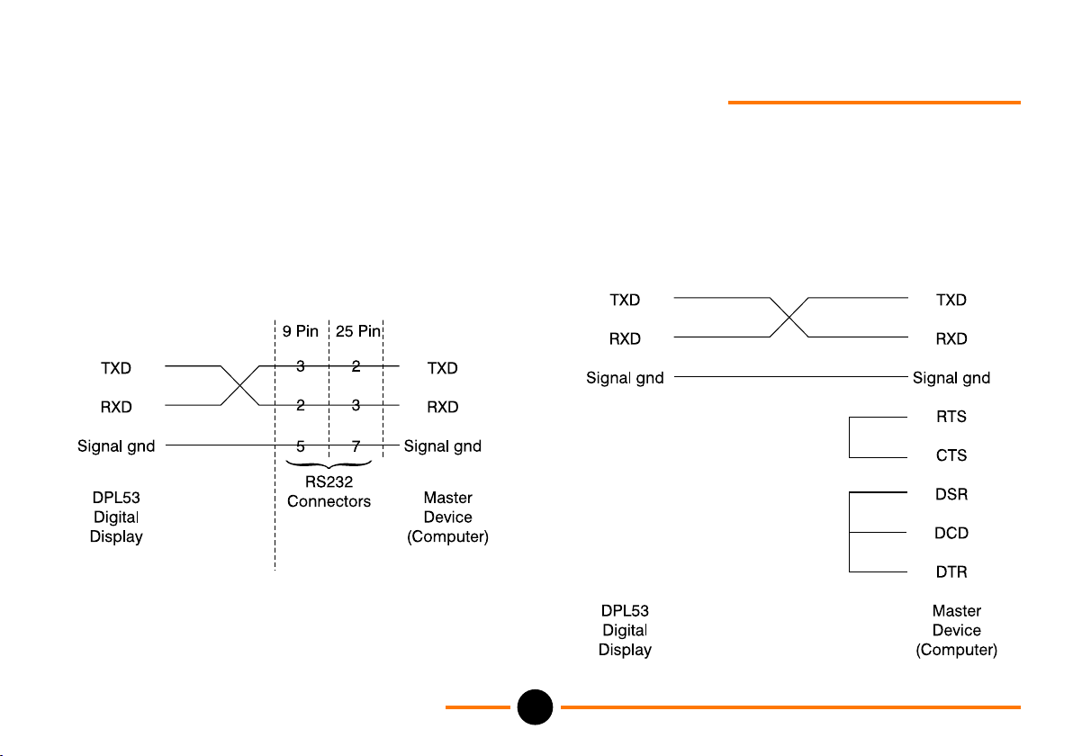
APPLICATION NOTE:
Simple connection between DPL53 Digital Display and
Master device. (Computer).
Connection between DPL53 Digital Display and Master
device. (Computer).
(Using NO flow control between Master device (i.e.
PC)).
8.0: R232 Communications with DPL53
(Setting Master device which has flow control signals).
39
M-3334 09/05DPL53
Page 42

8.0: RS232 Communications with DPL53
8.4 General format of commands
[address] is the communications address of the
All commands sent to the DPL53 must be written in
upper case.
[command] is a DPL53 command.
The syntax for a command to the DPL53 is as follows:
[location] is the DPL53 internal analogue or logic
;E_[address]_[command]_[location]_[data]<CR><LF>
DPL53, in the range 1 to 247.
location.
where:
; must start every command. If there is a ";" in the
middle of a command, the DPL53 will ignore
everything before the ";". You can abandon a
command by typing ";" at the end of it.
E is optional. This will cause the DPL53 to echo the
command before responding.
_ indicates a SPACE.
8.0: R232 Communications with DPL53
[data] for read commands (RA and RL) this
parameter specifies how many analogue or
logic locations are to be read. For write
commands (SA and SL), defines how many
to be written to the specified analogue or
logic location.
<CR> is a carriage return.
<LR> is a line feed.
40
M-3334 09/05DPL53
Page 43

8.0: RS232 Communications with DPL53
8.5 Commands
8.5.1 RA command
Description.
Read an analogue location within the DPL53.
Example Command. ;E_001_RA_2_1<CR><LF>
Part Description
;E starts the message and requests the
DPL53 to echo the command before
replying.
001 is the communications address of the
DPL53.
RA_2_1 is the command to read the value from
1 analogue location 2.
<CR><LF> marks the end of the command.
Reply.
;E_001_RA_2_1_+123.45<CR><LF>
Part Description
;E_001_RA_2_1 is the echo of the original command.
+123.45 is the value from location 2.
8.0: R232 Communications with DPL53
41
M-3334 09/05DPL53
Page 44

8.0: RS232 Communications with DPL53
8.5.2 SA Command
Description.
Set an analogue location within the DPL53.
Example Command. ;001_SA_63_100<CR><LF>
Part Description
;001 is the communications address of the
DPL53.
SA_63_100 is the command to set the value of
analogue location 63 to 100.
<CR><LF> marks the end of the command.
Reply. OK<CR><LF>
Part Description
; due to there being no ;E, the echo of
the original command.
OK message reply from DPL53, saying
message was received and understood.
8.0: R232 Communications with DPL53
42
M-3334 09/05DPL53
Page 45

8.0: RS232 Communications with DPL53
8.5.3 RL Command
Description.
Read the state of a logic location within the DPL53.
Example Command. ;E_001_RL_48_1<CR><LF>
Part Description
;E starts the message and requests the
DPL53 to echo the command before
replying.
001 is the communications address of the
DPL53.
RL_48_1 is the command to read the values from
location 48.
<CR><LF> marks the end of the command.
Reply. ;E_001_RL_48_1_ON<CR><LF>
Part Description
;E_001_RL_48_1 is the echo of the original command.
ON is the value from location 48.
8.0: R232 Communications with DPL53
43
M-3334 09/05DPL53
Page 46

8.0: RS232 Communications with DPL53
8.5.4 SL Command
Description.
Sets the state of a logic location within the DPL53.
Example Command. ;001_SL_140_ON<CR><LF>
Part Description
;001 is the communications address of the
DPL53.
SL_140_ON is the command to set the logic
locations state to ON at location 140.
<CR><LF> marks the end of the command.
Reply. OK<CR><LF>
Part Description
; due to there being no ;E, the echo of
the original command.
OK message reply from DPL53, saying
message was received and understood.
8.0: R232 Communications with DPL53
44
M-3334 09/05DPL53
Page 47
8.0: RS232 Communications with DPL53
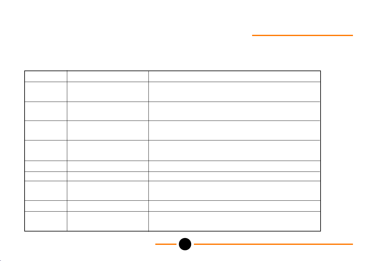
8.6 Error Messages
If the command is incorrect, the DPL53 returns a # followed by an error code. The error codes are as follows.
Error Code Meaning Example/Explanation
1 Invalid message ;E_001_RS_31_3<CR><LF>
"RS" is not a valid command.
2 Invalid/Read only location ;E_001_SL_33ON<CR><LF>
Logic location 33 is read only location.
3 Non existent location ;E_001_RA_310_1<CR><LF>
Analogue location 310 does not exist.
4 Invalid value ;E_001_RA_21_ON<CR><LF>
ON is not a valid value for analogue location 21.
5 Unaccepted value The DPL53 is inside a Configuration Menu.
6 Instrument error The DPL53 is not operating correctly.
7 Reserved location ;E_001_SA_91_100<CR><LF>
Analogue location 92 is a reserved location.
8 Too many data requests The DPL53 is still busy dealing with previous commands.
9 Too many arguments ;E_001_RA_SA_31_3<CR><LF>
There are two commands present, "RA" and "SA".
8.0: R232 Communications with DPL53
45
M-3334 09/05DPL53
Page 48
9.0: DPL53 Messages
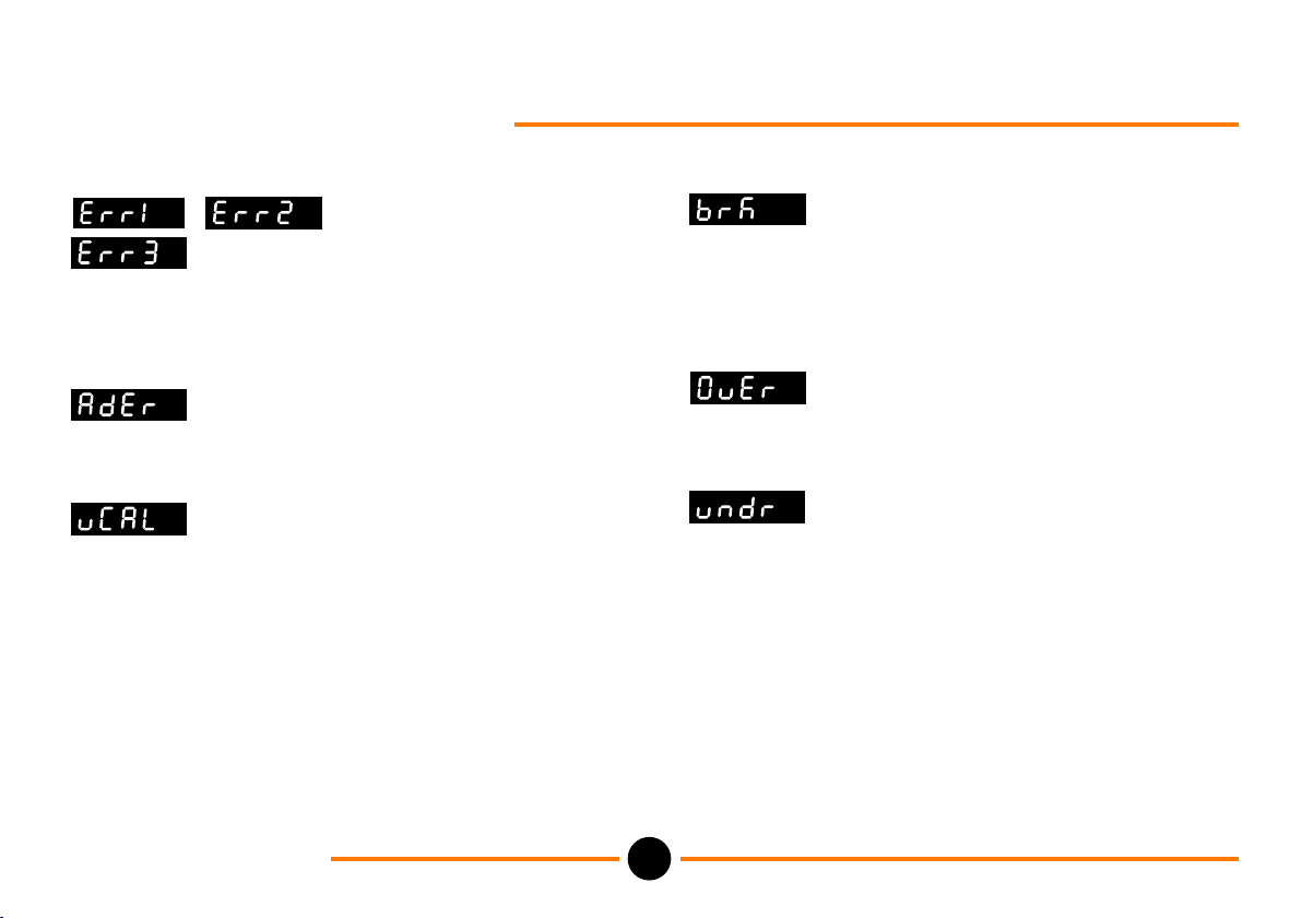
9.1 Error Messages
These messages indicate that an error has
been detected in one of the instruments internal
memory areas as part of power up self test sequence.
The instrument has detected a problem
with the sensor resulting in an open circuit input, this
may be caused by a break in one of the leads from the
transducer or a fault in one of the transducer elements.
This indicates that the instrument has
detected a fault in its measurement circuitry.
The instrument has detected a problem or
error in its non volatile memory resulting in a loss of
calibration data.
Note: For any of the above error messages return the
instrument to the supplier.
9.0: DPL53 Messages
DPL53
The measured value is too large positively
to be displayed, or is above the specified input range.
The measured value is too low negatively
to be displayed, or is below the specified minimum
input for the selected range.
Note: For any of the above messages check instrument
settings.
46
M-3334 09/05
Page 49
9.0: DPL53 Messages
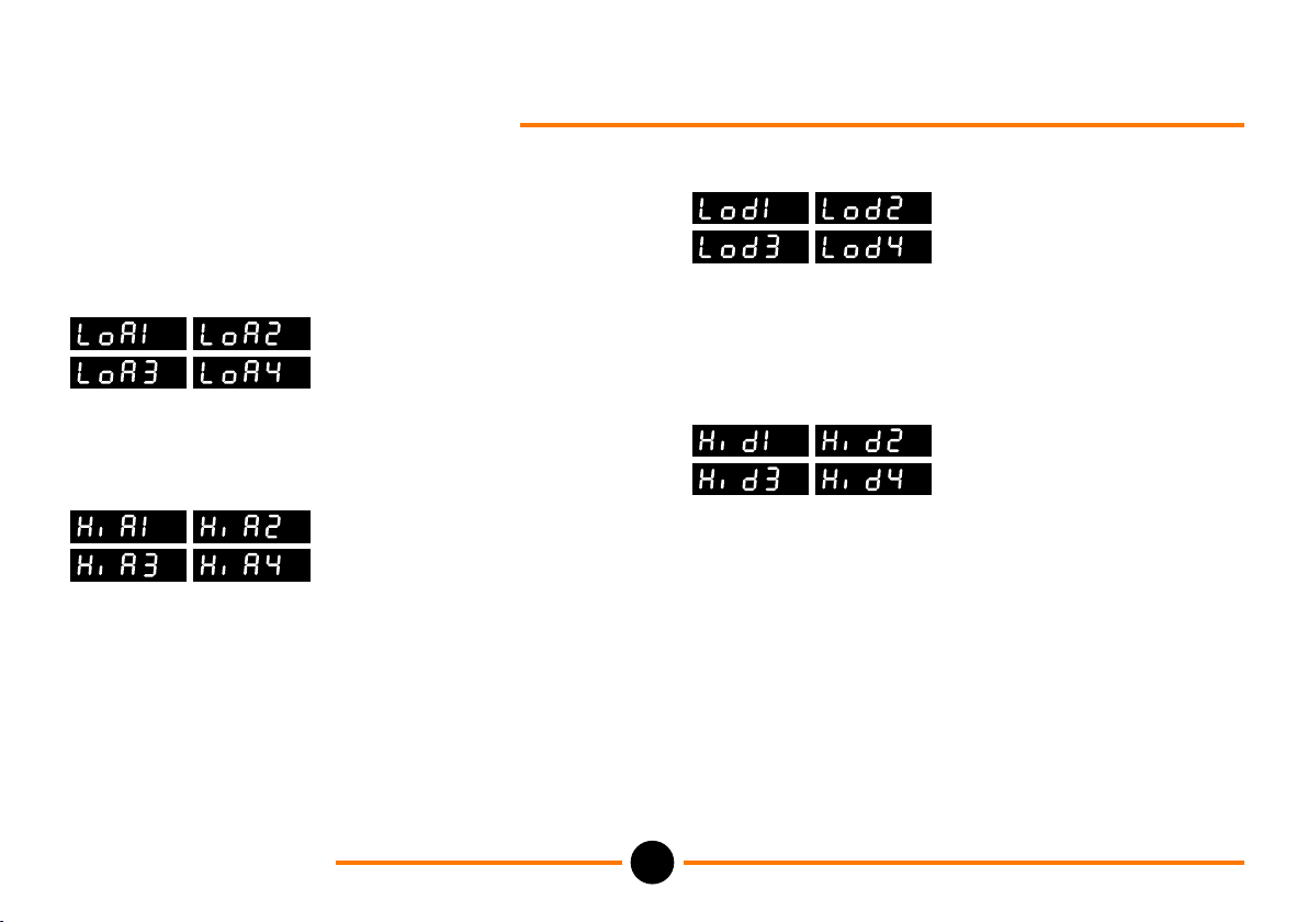
9.2 Alarm Messages
Alarm messages will be displayed alternately with the
normal display only one alarm message will be
displayed at any time.
Low alarm has been triggered on the indicated alarm.
eg: LoA3 = Low Alarm, Alarm 3.
High alarm has been triggered on the indicated alarm.
Deviation type alarm has been triggered on the
indicated alarm at the low deviation setpoint.
eg: Lod4 = Low Deviation Alarm, Alarm 4.
Deviation type alarm has been triggered on the
indicated alarm at the high deviation setpoint.
9.0: DPL53 Messages
DPL53
47
M-3334 09/05
Page 50
Appendix A: Control Panel Connections
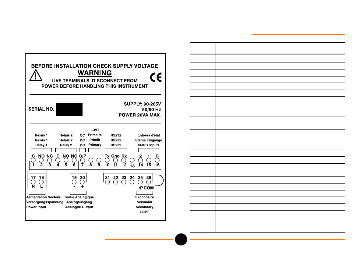
Terminal No alarm
1 Relay 1 - Common
2 Relay 1 - Normally Open
3 Relay 1 - Normally Closed
4 Relay 2 - Common
5 Relay 2 - Normally Open
6 Relay 2 - Normally Closed
7 O/P DC
8 LVDT Primary
9 LVDT Primary
10 RS232 Tx
11 RS232 Gnd
12 RS232 Rx
13 N/C
14 Status (Logic) Input 2
15 Status (Logic) Input 1
16 Status Input Common (GND)
17 Power Input Neutral (-)
18 Power Input Live (+)
19 High Speed Analogue Output 20 High Speed Analogue Output +
21 N/C
22 N/C
23 N/C
24 N/C
25 LVDT Secondary
26 LVDT Secondary
Appendix A: Connections
48
M-3334 09/05DPL53
Page 51
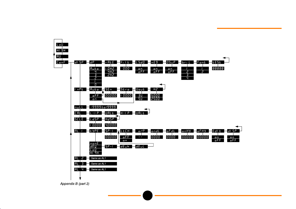
Appendix B: DPL53 Menu Options (Part 1)
Appendix B:DPL53 Menu Options
DPL53
49
M-3334 09/05
Page 52
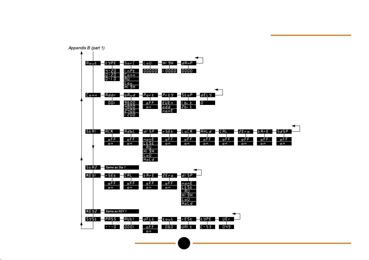
Appendix B: DPL53 Menu Options (Part 2)
Appendix B:DPL53 Menu Options
50
M-3334 09/05DPL53
Page 53

Appendix C: Specification for DPL53
Excitation
Voltage 3V AC rms. or 5V AC rms.
selectable
Frequency 2.5kHz or 5kHz selectable
Temperature drill (amplitude) <100ppm/°C
(frequency) <100ppm/°C
High Speed Analogue O/P
Output ±10V maximum
Response Output filter -3dB @ 125Hz
Analogue Output
Ranges 0-10V, 0-20mA or 4-20mA
selectable
Accuracy 0.2% of span
Temperature drift <100ppm/°C
Response 100% within 400mS
Resolution 0.05% (5mV or 0.01mA)
Supply 90 - 265V AC
50 - 60Hz
20VA max.
Operating Conditions
Ambient Temperature Storage -10°C to 70°C
(14° to 158°F)
Operating 10°C to 50°C
(50° to 122°F)
Humidity 10% to 95% Non-condensing
Input
ADC High precision Sigma Delta
Input range 0.05V rms. - 5V rms.
Resolution 18bit
Non Linearity <0.02%
Temperature drift <50PPM 1°C
(<50PPM 33.8°F)
Stability <0.01% FSO after 15 minutes
Input Impedance 100kW
Common mode rejection >150dB
Series mode rejection >70dB @ 50/60Hz
Appendix B:Specification for DPL53
51
M-3334 09/05DPL53
Page 54
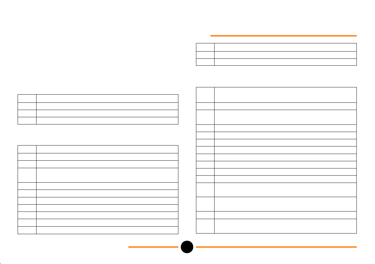
Appendix D: Memory locations
A.1 Analogue Memory Locations.
(RW) = Read / Write (RO) = Read Only
(WO) = Write Only
Easy Recall
0 (RO) Instrument Type e.g. DPL53
1 (RO) Measured Value, Unfiltered
2 (RO) Display Value, Filtered
3 (WO) Comms Display Value
Factory info
4 (RO) Factory Options
5 (RO) Number of Relays o/p fitted
6 Reserved
7 (RO) First Four digits of Serial
(datecode)e.g.0398
8 (RO) Last Four digits of Serial code
9 (RO) Firmware version (Format 99.99 or 9.99)
10 (RO) Firmware creation date (Year)
11 (RO) Firmware creation date (Month)
12 (RO) Firmware creation date (Day)
13 (RO) Firmware creation date (Hour)
14 (RO) Firmware creation date (Minute)
15 (RO) Firmware creation date (Second)
16 (WO) Comms display value
17 (RO) Stack Percentage used
Factory Test
18 (RO) reason for reset: 0=power 1=cop2=com
3-13=error 14=syst/com
19 (RO) memory Leak record: 255=no error
20 (RO) MCU portA - analog o/p v/I selection, load
cell gain applied
21 (RO) MCU portD
22 (RO) MCU portE - keys and status inputs
23 (RO) MCU portG - relay/ttl outputs
24 (RO) raw load cell input mV/V
25 Reserved
26 Reserved
27 (RO) channel A as a 0..1 ratio of span
28 (RO) channel B as a 0..1 ratio of span
29 (RO) zero offset applied when activated by Zero
function key/autozero
30 (RO) tare offset applied when activated by Tare
function key
31 (RO) null value: %FSD distance from null point
32 (RO) timer. Incremented every 20mS. Rolls over
at 32767 to 0
Appendix D: Memory locations
52
M-3334 09/05DPL53
Page 55
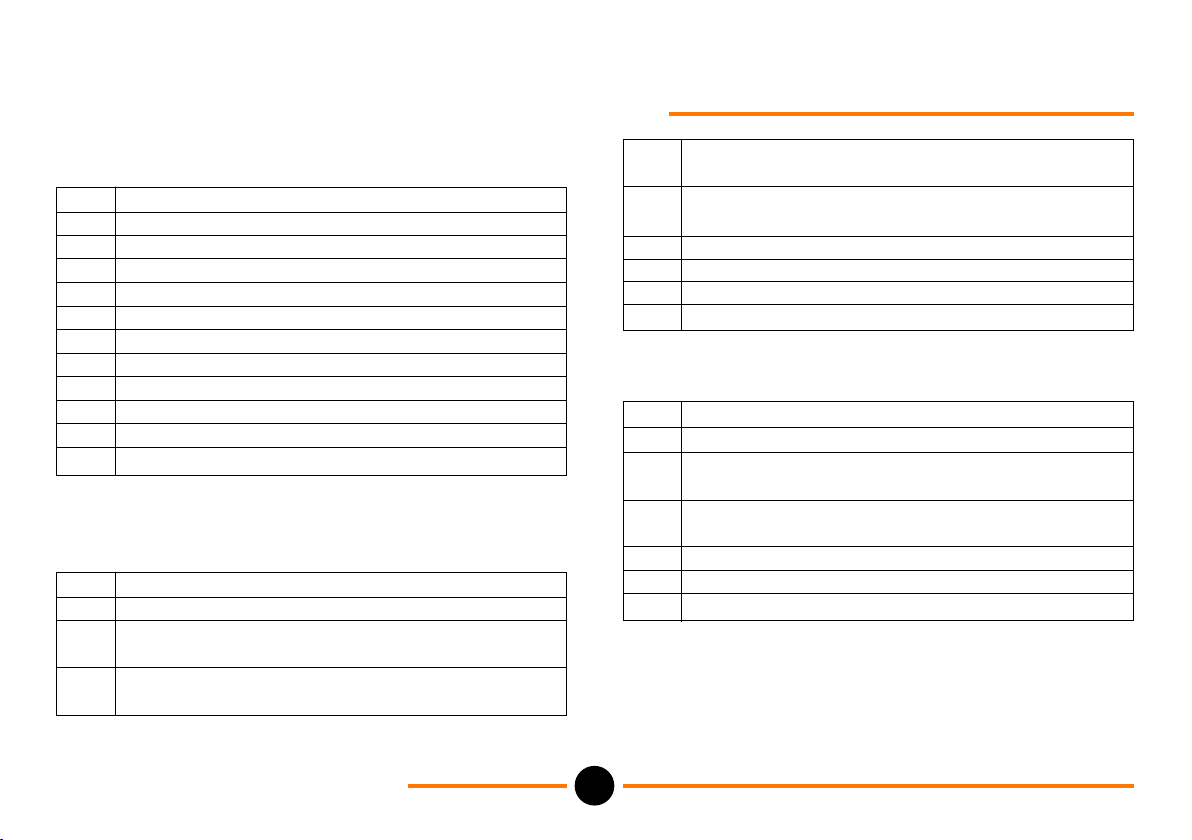
Appendix D: Memory locations
Realtime
33 (RO) analogue level on status1 (default 0 to
5000mV)
34 (RO) analogue level on status2 (default 0 to
5000mV)
35 (RO) Low Value
36 (RO) High Value
37 (RO) Average Value
38 (RO) unfiltered measured value
39 (RO) filtered displayed value
40 Reserved
ê
50 Reserved
Display setup
51 Reserved
52 Reserved
53 (RW) sorc:display source:
0=inpt,1=high,2=low,3=av,4=comm
54 (RW) dp: digits to right of decimal point; 0 to 4
or 5=auto
55 (RW) rate: display update
rate;0=2Hz,1=4Hz,2=10Hz
56 (RW) filt: display filter time; 0 to 999 sec (will be
0.0 to 99.9s)
57 (RW) bril: display Brilliance; 0 to 3, 3=brightest
58 Reserved
ê
61 Reserved
Input Setup
62 Reserved
63 (RW) sen: sensitivity mV/V/length_of_unit
64 (RW) stroke: in the same units of length used in
sensitivity
65 (RO) gain: load cell i/p GAIN;
0=x,1=x5,2=x10,3=x100
66 Reserved
ê
71 Reserved
Appendix D: Memory locations
53
M-3334 09/05DPL53
Page 56
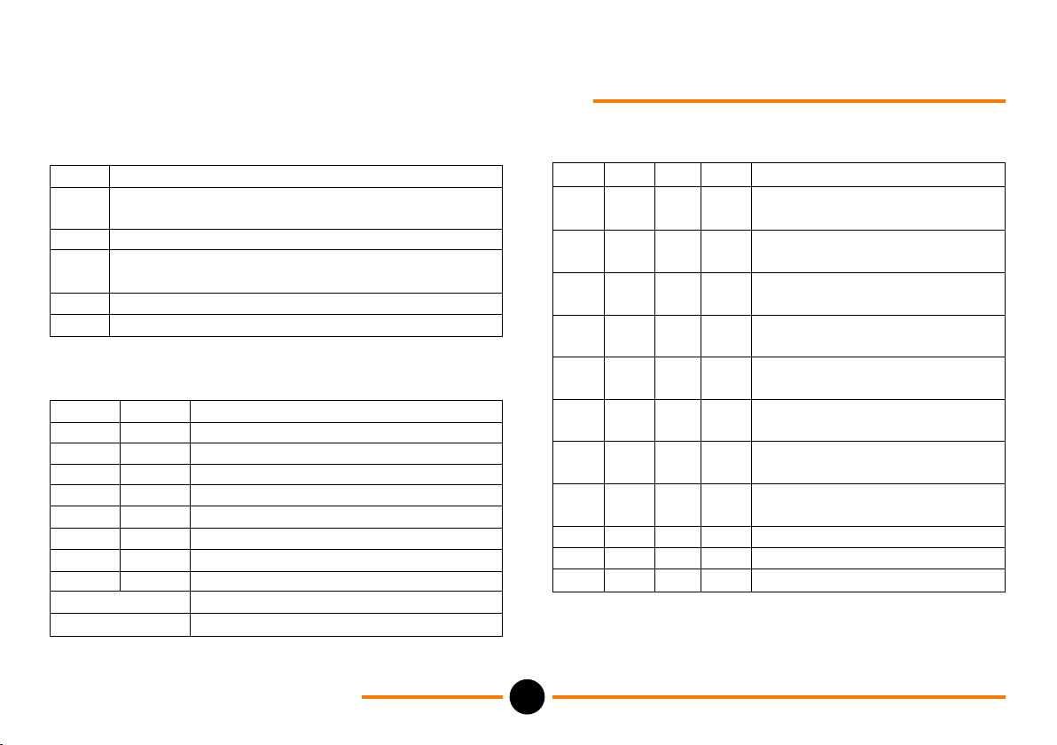
Appendix D: Memory locations
Scaling - for load cell input
72 Reserved (for user linearisation points)
73 (RW) Ldsp: Low Cal point display value (in units
of weight)
74 (RW) L-iP: Low Cal Point input value in mV/V
75 (RW) Hdsp: High Cal point display value (in
units of weight)
76 (RW) H-iP: High Cal point input value in mV/V
77 - 99 Reserved ( for User linearisation Cal. Points)
Analog Scaling setup
Sta1 Sta2
100 101 (RW) high cal point scaled level
(0_5000) default=5000 (for mV)
102 103 (RW) low cal point scaled level
(0_5000) default=0 (for mV)
104 105 (RW) high cal point input level (0 to
255) default=255 (255=5V)
106 107 Low cal point input level (0 to 255)
0=default (0=0V)
108 Reserved
109 Reserved
Alarm Number
1 2 3 4
110 125 140 155 (RW) type: 0=high 1-=low
2=dev 3=none
111 126 141 156 (RW) sp: septpoint -19999 to
99999
112 127 142 157 (RW) devh: deviation above
sp -19999 to 99999
113 128 143 158 (RW) devL: deviation below
sp -19999 to 99999
114 129 144 159 (RW) ondL: on delay 0 to
9999 s
115 130 145 160 (RW) ofdL: off delay 0 to
9999 s
116 131 146 161 (RW) onhy: on hysteresis -
19999 to 99999
117 132 147 162 (RW) ofhy: off hysteresis -
19999 to 99999
118 133 148 163 Reserved
ê ê ê ê
124 139 154 169 Reserved
Appendix D: Memory locations
54
M-3334 09/05DPL53
Page 57
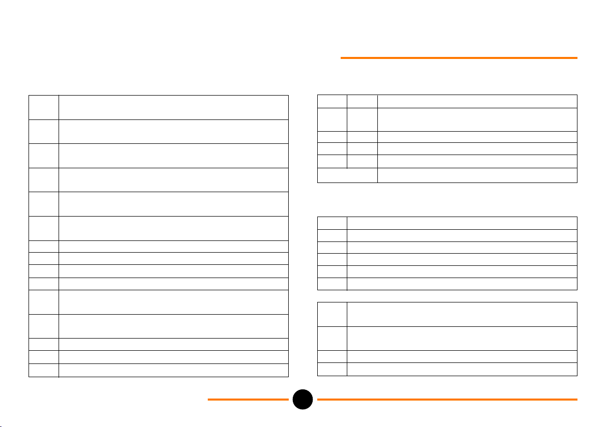
Appendix D: Memory locations
Analog Output setup
170 (RW) type: 0=0_10V 1=0_20mA (Low_high cal
point)default=2
171 (RW) sorc: 0=inpt 1=high 2=low 3=av
4=comm(a175) default=0
172 (RW) low: display value corresp.to low aout cal
point. Default=0
173 (RW) high: display value corresp.to high aout
cal point. Default=100
174 (RW) Damp: damping filter 0_999 s (to be: 0.0 to
99.9) default=0
175 (RW) REALTIME source of analog o/p when
type=4(=comm(a175))
176 Reserved
ê
181 Reserved
182 (RO) addr: instrument address 1_247 default=1
183 (RO) baud: baud rate 0=1200 1=2400 2=4800
3=9600 default=3
184 (RO) prty: Parity 0=odd 1=even 2=none default
= 1
185 Reserved
ê
196 Reserved
Status Input Number
1 2
197 201 (RW) disp: 0=none 1=hold 2=low
3=high 4=av 6=Ltst default=0
198 202 Reserved
ê ê
200 204 Reserved
205 Reserved
Function Key Action setup
1 2
206 210 (RW) disp: 0=none 1=hold 2=low
3=high 4=av 5=Ltst
207 211 Reserved
ê ê
209 213 Reserved
214 (RW) Avti: Period in seconds over which
average is taken default=1
215 (RW) tout: keypad inactivity timeout to Conf
mode exit default=60
216 Reserved
ê
Appendix D: Memory locations
55
M-3334 09/05DPL53
Page 58
Appendix D: Memory locations
218 Reserved
Relay/TTL O/p - setup
219 221 223 225 (RW) puls:dely 0.1 to 4.9
secs default=0.5s
220 222 224 226 Reserved
D.2. Logic Memory Locations.
(RW) = Read / Write (RO) = Read Only
(WO) = Write Only
Factory Info
0 (RO) Config. Status: ON=in Config. Mode
1 (RO) Calibration Mode: ON=in Calibration Mode
2 (RO) Calibrated: ON=Calibration done or
defaulted
3 Reserved
ê
5 Reserved
Realtime Info
6 (RO) function key1 (leftmost) state:
ON=Pressed
7 (RO) funtion key2 (rightmost) state:
ON=Pressed
8 (RO) status input1 state: ON=connected
9 (RO) status input2 state: ON=connected
10 (RO) alarm1 state: ON=activated
11 (RO) alarm2 state: ON=activated
12 (RO) alarm3 state: ON=activated
13 (RO) alarm4 state: ON=activated
14 (RO) output1 relay state: ON=closed/activated
15 (RO) output2 relay state: ON=closed/activated
16 (RO) output3 relay state: ON=closed/activated
17 (RO) output4 relay state: ON=closed/activated
18 Reserved
ê
23 Reserved
24 (RO) calibration in progress: ON=busy
Appendix D: Memory locations
56
M-3334 09/05DPL53
Page 59
Appendix D: Memory locations
Runtime Control
25 (RW) ON=Do FastCal. Repeat when clear while
L24 ON.
26 (RW) ON=Alarm Acknowledge
27 (RW) ON=Reset high, Low,av,control SP's, Pick
SP's
28 (RW) ON=Reset High display value only
29 (RW) ON=Reset Low display value only
30 (RW) ON=Reset Average display value only
31 (RW) ON=Perform Zero
32 (RW) ON=Undo Zero
33 (RW) ON=Perform Tare
34 (RW) ON=Un-Tare
35 Reserved
ê
41 Reserved
Scaling Control
42 (RW) ON=read L-iP (reads OFF when done -see
also L44)
43 (RW) ON=read H-iP (reads OFF when done -
see also L44)
44 (RW) ON=re-scale. Do when L-iP, H-iP,Hdsp and
Ldsp are ALL as required
45 Reserved (for User linearisation)
46 Reserved
Display setup
47 (RW) font:ON=Display font2, OFF=Display font1
default=OFF
48 (RW) 0sup: ON=Leading zeros blank
OFF=Leading zeros on default=ON
49 (RW) Lsd0: ON=Least signif. digit 0
OFF=normal default=OFF
50 (RW) neg: ON=neg display enable OFF=neg
values show 0 default=ON
51 Reserved
ê
54 Reserved
Input Setup
55 (RW) Hz: excitation frequency OFF=2.5kHz,
On=10kHz default=OFF
56 (RW) rms: excitation voltage OFF=1V, ON=3V
default=OFF
Appendix D: Memory locations
57
M-3334 09/05DPL53
Page 60
Appendix D: Memory locations
57 (RW) Auto: ON=autogain on OFF=autogain off
default=OFF
58 (RW) ON=calculate new gain now based on
new L-iP &/or H-iP
59 Reserved
60 Reserved
Alarm setup
Al-1 Al-2 Al-3 Al-4 Function
61 71 81 91 (RW) O/P:1---: ON=relay O/p1
set by alarm Default=OFF
62 72 82 92 (RW) O/P:-2--: ON=relay O/p1
set by alarm Default=OFF
63 73 83 93 Reserved
64 74 84 94 Reserved
65 75 85 95 (RW) LtcH: ON=Latching
Default=OFF
66 76 86 96 (RW) Edit: ON=Panel Key edit
enabled Default=OFF
67 77 87 97 (RW) disp: ON=Warning
Message Default=ON
68 78 Reserved
88 98 (RW) L-SP: ON=Linked to
Alarm minus 2 default=OFF
69 79 89 99 Reserved
70 80 90 100 Reserved
Comms setup
101 (RW) ON=7 digits values from instrument
OFF=5 digits Default=OFF
102 (RW) Prot: ON=all analog/logic locations write
protected Default=OFF
103 (RO) StoP: ON=2 stop bits OFF=1 stop bit
104 Reserved
ê
111 Reserved
Status Input setup
112 125 (RW) tAre: ON=tare display
Default=OFF
113 126 (RW) Ack: ON=acknowledge all latched
alarms Default=OFF
114 127 (RW) Adbl: ON=disable alarms
115 128 (RW) rSEt: ON=reset
high/low/av/Control SP's Default=OFF
Appendix D: Memory locations
58
M-3334 09/05DPL53
Page 61
Appendix D: Memory locations
116 129 (RW) Lock: ON=disable front panel keys
Default=OFF
117 130 (RW) hOLd: ON=hold the analogue
output value Default=OFF
118 131 (RW) ZerO: ON=zero display
Default=OFF
119 132 (RW) disP: ON=show STA? Display
Default=OFF
120 133 (RW) CAL: ON=begin fast cal (need>1
Activation Default=OFF
121 134 Reserved
ê ê
124 137 Reserved
Function Key Setup
1 (?) 2 (*) Function
138 146 (RW) rSEt: ON=reset
high/low/av/Control SP's default=OFF
139 147 (RW) tARe: ON=tare display
140 148 (RW) ZerO: ON=zero display
141 149 (RW) CAL: ON=do fastcal (need more
than 1 activation) default=OFF
142 150 Reserved
ê ê
145 153 Reserved
System setup
154 (RW) dFLt: ON=default instrument setup
155 (RW) rSEt: ON=Reset instrument (as on power
up)
156 Reserved
ê
159 Reserved
Relay Output Setup
160 165 170 175 (RW) tYPE: ON=true
OFF=false(inverted)
Default=ON
161 166 171 176 (RW) PulS.EnAb: ON=pulsed
OFF=normal Default=OFF
162 167 172 177 Reserved
163 168 173 178 Reserved
164 169 174 179 Reserved
Appendix D: Memory locations
59
M-3334 09/05DPL53
Page 62

WARRANTY/DISCLAIMER
OMEGA ENGINEERING, INC. warrants this unit to be free of defects in materials and
workmanship for a period of 13 months from date of purchase. OMEGA Warranty adds
an additional one (1) month grace period to the normal one (1) year product
warranty to cover handling and shipping time. This ensures that OMEGA’s customers
receive maximum coverage on each product.
If the unit malfunctions, it must be returned to the factory for evaluation. OMEGA’s
Customer Service Department will issue an Authorized Return (AR) number immediately
upon phone or written request. Upon examination by OMEGA, if the unit is found to be
defective, it will be repaired or replaced at no charge. OMEGA’s WARRANTY does not
apply to defects resulting from any action of the purchaser, including but not limited to
mishandling, improper interfacing, operation outside of design limits, improper repair, or
unauthorized modification. This WARRANTY is VOID if the unit shows evidence of having
been tampered with or shows evidence of having been damaged as a result of excessive
corrosion; or current, heat, moisture or vibration; improper specification; misapplication;
misuse or other operating conditions outside of OMEGA’s control. Components which
wear are not warranted, including but not limited to contact points, fuses, and triacs.
OMEGA is pleased to offer suggestions on the use of its various products. However,
OMEGA neither assumes responsibility for any omissions or errors nor assumes
liability for any damages that result from the use of its products in accordance with
information provided by OMEGA, either verbal or written. OMEGA warrants only that the
parts manufactured by it will be as specified and free of defects. OMEGA MAKES NO
OTHER WARRANTIES OR REPRESENTATIONS OF ANY KIND WHATSOEVER,
EXPRESS OR IMPLIED, EXCEPT THAT OF TITLE, AND ALL IMPLIED WARRANTIES
INCLUDING ANY WARRANTY OF MERCHANTABILITY AND FITNESS FOR A
PARTICULAR PURPOSE ARE HEREBY DISCLAIMED. LIMITATION OF LIABILITY: The
remedies of purchaser set forth herein are exclusive, and the total liability of OMEGA
with respect to this order, whether based on contract, warranty, negligence,
indemnification, strict liability or otherwise, shall not exceed the purchase price of the
component upon which liability is based. In no event shall OMEGA be liable for
consequential, incidental or special damages.
CONDITIONS: Equipment sold by OMEGA is not intended to be used, nor shall it be
used: (1) as a “Basic Component” under 10 CFR 21 (NRC), used in or with any nuclear
installation or activity; or (2) in medical applications or used on humans. Should any
Product(s) be used in or with any nuclear installation or activity, medical application,
used on humans, or misused in any way, OMEGA assumes no responsibility as set
forth in our basic WARRANTY/ DISCLAIMER language, and, additionally, purchaser will
indemnify OMEGA and hold OMEGA harmless from any liability or damage whatsoever
arising out of the use of the Product(s) in such a manner.
RETURN REQUESTS / INQUIRIES
Direct all warranty and repair requests/inquiries to the OMEGA Customer Service
Department. BEFORE RETURNING ANY PRODUCT(S) TO OMEGA, PURCHASER
MUST OBTAIN AN AUTHORIZED RETURN (AR) NUMBER FROM OMEGA’S
CUSTOMER SERVICE DEPARTMENT (IN ORDER TO AVOID PROCESSING DELAYS).
The assigned AR number should then be marked on the outside of the return package
and on any correspondence.
The purchaser is responsible for shipping charges, freight, insurance and proper
packaging to prevent breakage in transit.
FOR W
ARRANTY RETURNS, please
have the following information available
BEFORE contacting OMEGA:
1. Purchase Order number under
which the product was
PURCHASED,
2. Model and serial number of the
product under warranty, and
3. Repair instructions and/or specific
problems relative to the product.
OMEGA’s policy is to make running changes, not model changes, whenever an
improvement is possible. This affords our customers the latest in technology and
engineering.
OMEGA is a registered trademark of OMEGA ENGINEERING, INC.
© Copyright 1998 OMEGA ENGINEERING, INC. All rights reserved. This document
may not be copied, photocopied, reproduced, translated, or reduced to any electronic
medium or machine-readable form, in whole or in part, without the prior written consent
of OMEGA ENGINEERING, INC.
FOR NON-WARRANTY REPAIRS,
consult OMEGA for current repair
charges. Have the following information
available BEFORE contacting OMEGA:
1. Purchase Order number to cover
the
COST of the repair,
2. Model and serial number of the
product, and
3. Repair instructions and/or specific
problems relative to the product.
DPL53
M-3334 09/05
Page 63

Where Do I Find Everything I Need for
Process Measurement and Control?
TEMPERATURE
q
Thermocouple, RTD & Thermistor Probes, Connectors,
Panels & Assemblies
q
Wire: Thermocouple, RTD & Thermistor
q
Calibrators & Ice Point References
q
Recorders, Controllers & Process Monitors
q
Infrared Pyrometers
PRESSURE, STRAIN AND FORCE
q
Transducers & Strain Gauges
q
Load Cells & Pressure Gauges
q
Displacement Transducers
q
Instrumentation & Accessories
OMEGA…Of Course!
DATA ACQUISITION
q
Data Acquisition & Engineering Software
q
Communications-Based Acquisition Systems
q
Plug-in Cards for Apple, IBM & Compatibles
q
Datalogging Systems
q
Recorders, Printers & Plotters
HEATERS
q
Heating Cable
q
Cartridge & Strip Heaters
q
Immersion & Band Heaters
q
Flexible Heaters
q
Laboratory Heaters
FLOW/LEVEL
q
Rotameters, Gas Mass Flowmeters & Flow Computers
q
Air Velocity Indicators
q
Turbine/Paddlewheel Systems
q
Totalizers & Batch Controllers
pH/CONDUCTIVITY
q
pH Electrodes, Testers & Accessories
q
Benchtop/Laboratory Meters
q
Controllers, Calibrators, Simulators & Pumps
q
Industrial pH & Conductivity Equipment
DPL53
ENVIRONMENTAL
MONITORING AND CONTROL
q
Metering & Control Instrumentation
q
Refractometers
q
Pumps & Tubing
q
Air, Soil & Water Monitors
q
Industrial Water & Wastewater Treatment
q
pH, Conductivity & Dissolved Oxygen Instruments
M-3334 09/05
 Loading...