

Page 1

Temperature & Process
Controller/Monitor
CNi8C-EN/DPi8C-EN
Page 2

Page 3

TABLE OF CONTENTS
Part 1: Introduction .....................................................................................1
1.1 Description ...................................................................................1
1.2 Safety Considerations ....................................................................2
1.3 Before You Begin ...........................................................................3
Part 2: Setup ................................................................................................4
2.1 Front Panel ...................................................................................4
2.2 Disassembly ...................................................................................5
2.3 Electrical Installation ......................................................................6
2.3.1 Power Connections ............................................................6
2.3.2 Rear Panel Connections ....................................................8
2.3.3 Thermocouple - Input Connection ....................................10
2.3.4 Two / Three / Four Wire RTD-Hookups ...........................11
2.3.5 Process Current - Wiring Hookup ....................................12
2.3.6 Process Voltage - Wiring Hookup ....................................12
2.3.7 Wiring Outputs - Wiring Hookup .......................................13
Part 3: Operation: Configuration Mode ...................................................16
3.1 Introduction .................................................................................16
Turning your device On for the First Time ........................16
Buttons Functions in Configuration Mode ........................17
i
Page 4

LIST OF FIGURES:
Figure 2.1 Front Panel Display ........................................................................4
Figure 2.2 Disassembly ...................................................................................5
Figure 2.3 Main Power Connections ...............................................................6
Figure 2.4 Rear View - For Models with Outputs: 22, 23, 33 ..........................7
Figure 2.5 Rear View - For Models with Outputs: 52, 53 ................................7
Figure 2.6 Rear View - For Models with Outputs: 00 ......................................8
Figure 2.7 Rear Panel Power and Output Connector Labels ..........................8
Figure 2.8 Rear Panel Input Connector Labels ...............................................9
Figure 2.9 Thermocouple Wiring Hookup .....................................................10
Figure 2.10 Two/Three/Four-wire RTD
a) RTD-1000 ohm and 500 ohm Wiring Hookup ..............................11
b) RTD-100 ohm Wiring Hookup ......................................................11
Figure 2.11 Process Current Wiring Hookup
(Internal and External Excitation) .................................................12
Figure 2.12 Process Voltage Wiring Hookup
a) Without Sensor Excitation ............................................................12
b) With Sensor Excitation .................................................................12
Figure 2.13 Output Connections:
a) Mechanical Relay and SSR Outputs – Wiring Hook up ...............13
b) Pulse and Analog Outputs – Wiring Hook up ...............................13
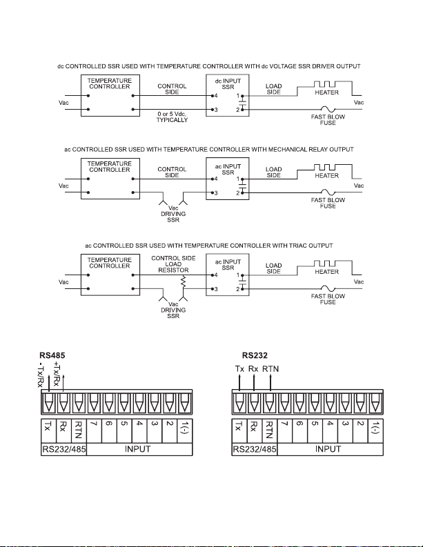
Figure 2.14 Typical Application .......................................................................14
Figure 2.15 Communication Output:
a) RS-232 Output – Wiring Hook up ................................................14
b) RS-485 Output – Wiring Hook up ................................................14
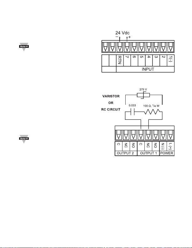
Figure 2.16 Excitation Output ..........................................................................15
Figure 2.17 Snubber Circuits Wiring Hookup ..................................................15
Figure A-1 Plug-Kit ........................................................................................18
LIST OF TABLES:
Table 2.1 Front Panel Annunciators ..............................................................4
Table 2.2 Fuse Requirement .........................................................................6
Table 2.3 Rear Panel Connector ...................................................................9
Table 2.4 TC Wire Color Chart ....................................................................10
Table 3.1 Button Function in Configuration Mode ........................................17
ii
Page 5
NOTES, WARNINGS and CAUTIONS
Information that is especially important to note is identied by the following labels:
• NOTE
• WARNING or CAUTION
• IMPORTANT
• TIP
NOTE: Provide you with information that is important to successfully
setup and use the Programmable Digital System.
CAUTION or WARNING: Tells you about the risk of
electrical shock.
CAUTION, WARNING or IMPORTANT: Tells you of circumstances or
practices that can affect the instrument’s functionality and must refer to
accompanying documents.
TIP: Provides you helpful hints.
PART 1
INTRODUCTION
1.1 Description
This device is a compact, wall-mountable controller/monitor that can be used for
applications that need a xed location, when a control panel is not required.
The controller/monitor supports a variety of temperature and process inputs. The
ip-top enclosure makes programming and wire access easy to use.
For complete specications or setup and programming of the
controller/monitor refer to the main operator manual.
1
Page 6
1.2 Safety Considerations
This device is marked with the international caution symbol. It is
important to read this manual before installing or commissioning this
device as it contains important information relating to Safety and
EMC (Electromagnetic Compatibility).
This device is a panel mount device protected in accordance with
EN 61010-1:2001, electrical safety requirements for electrical
equipment for measurement, control and laboratory. Installation of this
device should be done by qualied personnel. In order to ensure safe
operation, the following instructions should be followed.
This device has no power-on switch. An external switch or circuitbreaker shall be included in the building installation as a disconnecting
device. It shall be marked to indicate this function, and it shall be in
close proximity to the equipment within easy reach of the operator.
The switch or circuit-breaker shall meet the relevant requirements of
IEC 947–1 and IEC 947-3 (International Electrotechnical Commission).
The switch shall not be incorporated in the main supply cord.
Furthermore, to provide protection against excessive energy being
drawn from the main supply in case of a fault in the equipment, an
overcurrent protection device shall be installed.
• Do not exceed voltage rating on the label located on the top of
the device housing.
• Always disconnect power before changing signal and power
connections.
• Do not use this device on a work bench without its case for
safety reasons.
• Do not operate this device in ammable or explosive atmospheres.
• Unit mounting should allow for adequate ventilation to ensure
device does not exceed operating temperature rating.
• Use electrical wires with adequate size to handle mechanical
strain and power requirements. Install without exposing bare wire
outside the connector to minimize electrical shock hazards.
EMC Considerations
• Whenever EMC is an issue, always use shielded cables.
• Never run signal and power wires in the same conduit.
• Use signal wire connections with twisted-pair cables.
• Install Ferrite Bead(s) on signal wires close to the device if
EMC problems persist.
Failure to follow all instructions and warnings may result in injury!
2
Page 7

1.3 Before you Begin
Inspecting Your Shipment:
Remove the packing slip and verify that you have received everything
listed. Inspect the container and equipment for signs of damage as
soon as you receive the shipment. Note any evidence of rough handling
in transit. Immediately report any damage to the shipping agent. The
carrier will not honor damage claims unless all shipping material is
saved for inspection. After examining and removing the contents, save
the packing material and carton in the event reshipment is necessary.
Customer Service:
If you need assistance, please call the nearest Customer Service
Department, listed in this manual.
Manuals, Software:
The latest Operation and Communication Manual as well as free
configuration software are available from the website listed in this
manual.
If you have the Serial Communications you can easily configure the
device on your computer or on-line.
To Disable Outputs:
To ensure that menu changes are properly stored, Standby Mode should
be used during setup of the device. During Standby Mode, the device
remains in a ready condition, but all outputs are disabled. Standby Mode
is useful when maintenance of the system is necessary.
When the device is in “RUN” Mode, push d twice to disable all outputs
and alarms. It is now in “STANDBY” Mode. Push d once more to
resume “RUN” Mode.
PUSH d TWICE to disable the system during an EMERGENCY.
To Reset the Meter:
When the device is in the “MENU” Mode, push c once to direct device
one step backward of the top menu item.
Push c twice to reset device, prior to resuming “Run” Mode except
after “Alarms”, that will go to the “Run” Mode without resetting the
device.
3
Page 8
PART 2
MINIMUM 75 C WIRE SIZE REQUIREMENT
SETUP
2.1 Front Panel
NOTE: 1/2” or 16 METRIC DESIGNATOR
CONDUIT FITTINGS
(NOT INCLUDED WITH UNIT)
o
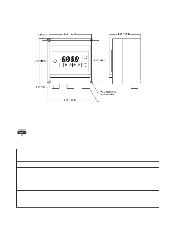
Figure 2.1 Front Panel Display
To maintain the NEMA 4X rating on the enclosure mounting: use the Wall
Mounting Hole Pattern as dimensioned.
This is the same hole pattern for the 4 screws that are used for the
disassembly of the enclosure.
Table 2.1 Front Annunciators
1 Output 1/Setpoint 1/ Alarm 1 indicator
2 Output 2/Setpoint 2/ Alarm 2 indicator
ºC °C unit indicator
ºF °F unit indicator
Changes display to Conguration Mode
a
and advances through menu items*
Used in Program Mode and Peak Recall*
b
Used in Program Mode and Valley Recall*
c
Accesses submenus in Conguration Mode
d
* See Part 3 Operation: Conguration Mode
and stores selected values*
4
Page 9
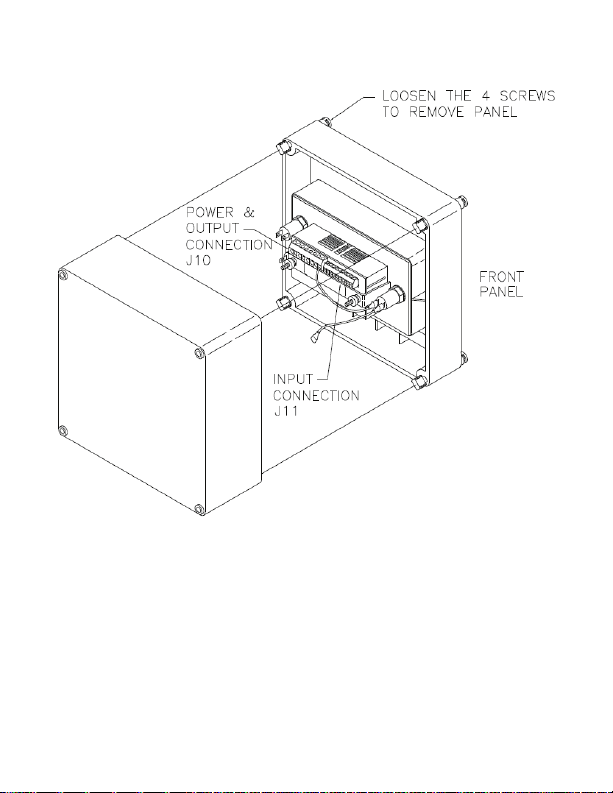
2.2 Disassembly
Figure 2.2 Disassembly
5
Page 10
2.3 Electrical Installation
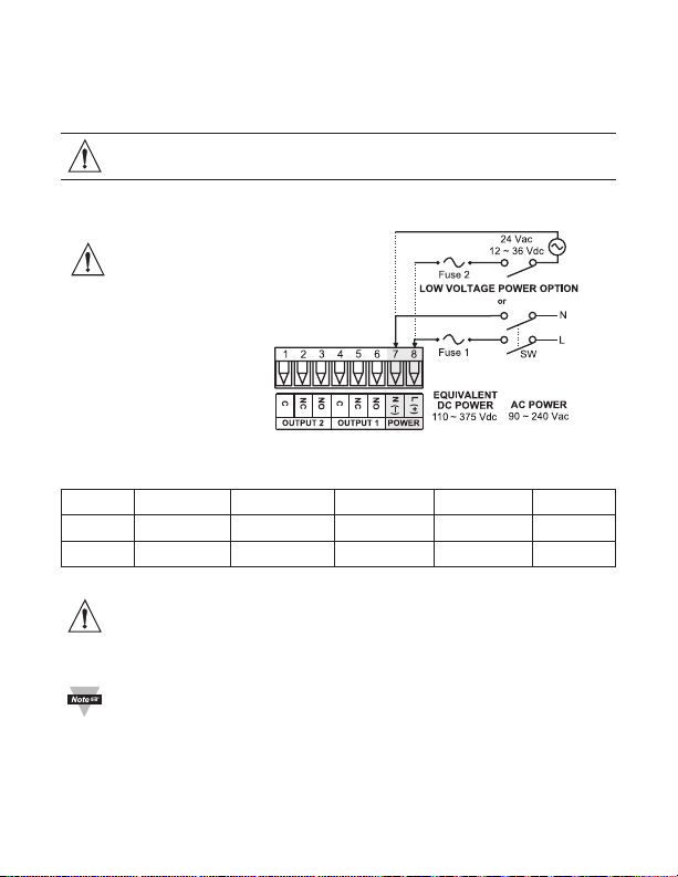
2.3.1 Power Connections
Caution: Do not connect power to your device until you have completed
all input and output connections. Failure to do so may result in injury!
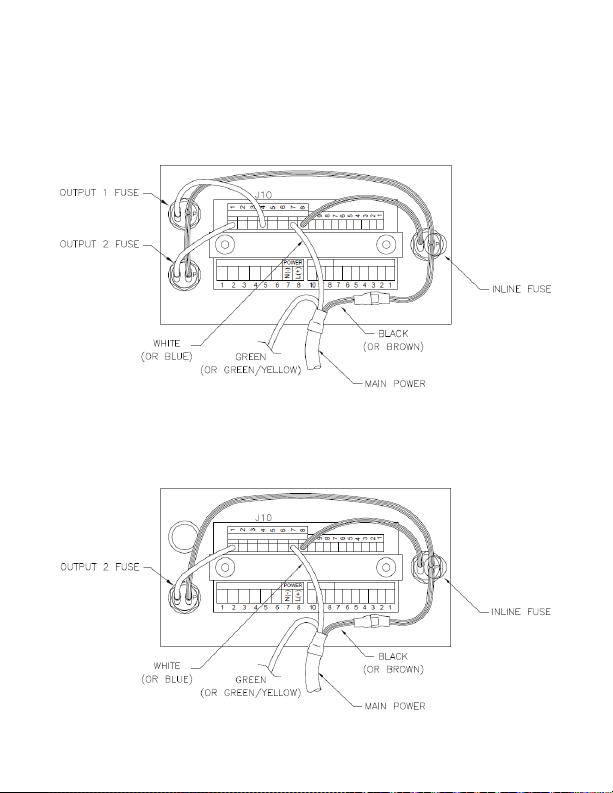
The main power has already been connected with power fuse and output fuse
(if required).
Use copper conductors
only for power connections.
Wires to be sized based upon
minumum of 75°C (167°F).
Figure 2.3 Main Power Connections
Table 2.2 Fuse Requirement (see specications)
FUSE Connector Output Type For 115 Vac For 230 Vac DC
FUSE 1 Power N/A 100 mA(T) 100 mA(T) 100 mA(T)
FUSE 2 Power N/A N/A N/A 400 mA(T)
For the low voltage power option, in order to maintain the same degree of
protection as the standard high voltage input power units (90 - 240 Vac),
always use a Safety Agency Approved DC or AC source with the same
Overvoltage Category and pollution degree as the standard AC unit
(90 - 240 Vac).
The Safety European Standard EN61010-1 for measurement, control,
and laboratory equipment requires that fuses must be specied based
on IEC127. This standard species for a Time-lag fuse, the letter code
“T”. The above recommended fuses are of the type IEC127-2-sheet III.
Be aware that there are signicant differences between the requirements
listed in the UL 248-14/CSA 248.14 and the IEC 127 fuse standards. As
a result, no single fuse can carry all approval listings. A 1.0 Amp IEC fuse
is approximately equivalent to a 1.4 Amp UL/CSA fuse. It is advised to
consult the manufacturer’s data sheets for a cross-reference.
6
Page 11
2.3.1 Power Connections (continued)
Rear View for Models:
Two SSR Relay Outputs “22”
SSR Relay and Form “C” Relay Outputs “23”
Two Form “C” Relay Outputs “33”
Figure 2.4 Rear View - For Models with Outputs: 22, 23, 33
Rear View for Models:
Analog and SSR Relay Outputs “52”
Analog and Form “C” Relay Outputs “53”
Figure 2.5 Rear View - For Models with Outputs: 52, 53
7
Page 12
2.3.1 Power Connections (continued)
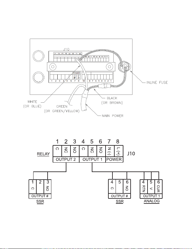
Rear View for Models:
Monitor Units
Figure 2.6 Rear View - For Models with no Outputs
2.3.2 Rear Panel Connections
Figure 2.7 Rear Panel Power and Output Connections
8
Page 13
2.3.2 Rear Panel Connections (continued)
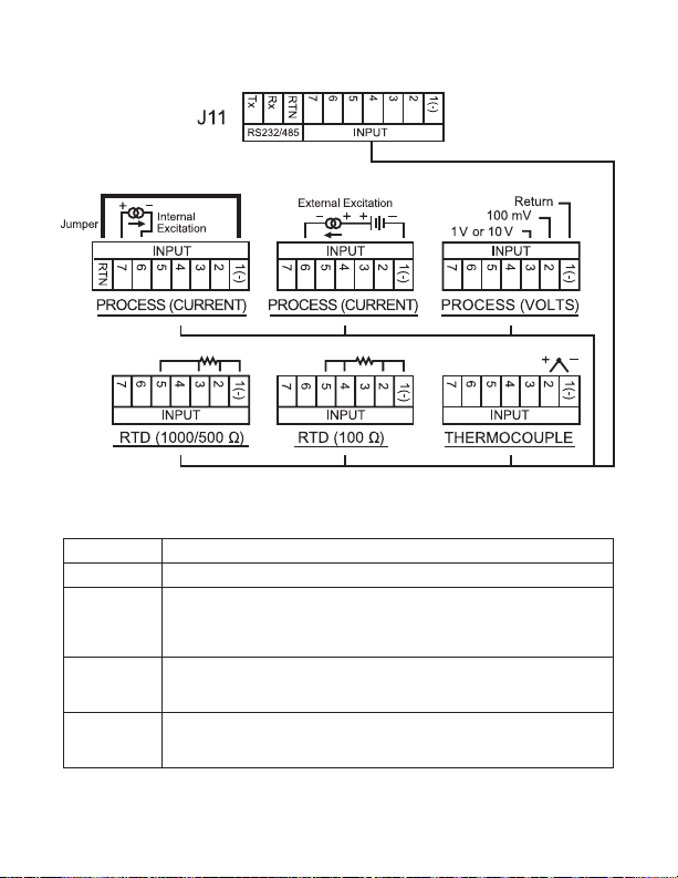
Figure 2.8 Rear Panel Input Connections
Table 2.3 Real Panel Connector
POWER AC/DC Power Connector: All models
INPUT Input Connector: All models TC, PR (Process), RTD
OUTPUT 1 Based on one of the following models:
OUTPUT 2 Based on one of the following models:
OPTION Based on one of the following models:
Relay SPDT
Solid State Relay
Analog Output (Voltage and Current)
Relay SPDT
Solid State Relay
RS232C or RS485 programmable
Excitation
9
Page 14
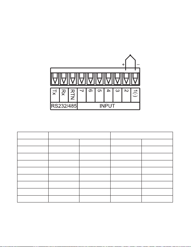
2.3.3 Thermocouple
The gure below shows the wiring hookup for any thermocouple type. For
example, for Type K hookup, connect the yellow wire to the “2” terminal and the
red wire to the “1(-)” terminal.
When conguring your device, select Thermocouple and Thermocouple
Type in the Input Type menu (see Part 3).
Figure 2.9 Thermocouple Wiring Hookup
Table 2.4 TC Wire Color Chart
Type Input Connector Jacket (External Insulation)
Terminal 1 (-) Terminal 2 (+) Extension Grade
J Red White Dark-Brown Black
K Red Yellow Dark-Brown Yellow
T Red Blue Dark-Brown Blue
E Red Purple Dark-Brown Purple
N Red Orange Dark-Brown Brown
R Red Black - Green
S Red Black - Green
B Red Gray - Black
10
Page 15
2.3.4 Two/Three/Four-Wire RTD
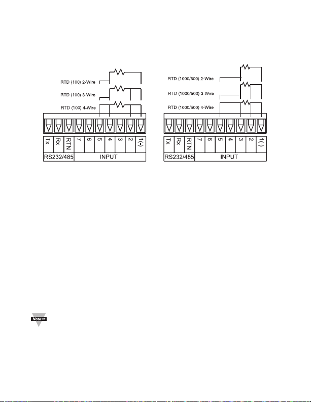
The gures below show the input connections and input connector jumpers
(shown in bold lines) required to hookup a 2-, 3- or 4-wire RTD.
Figure 2.10 a) RTD-100 ohm and b) RTD-100 ohm Wiring Hookup
500 ohm Wiring
Hookup
The two-wire connection is simplest method, but does not compensate for
lead-wire temperature change and often requires calibration to cancel lead-wire
resistance offset.
The three-wire connection works best with RTD leads closely equal in
resistance. The device measures the RTD, plus upper and lower lead drop
voltage and the subtracts twice the measured drop in the lower supply
current lead producing excellent lead-resistance cancellation for balanced
measurements.
The four-wire RTD hookup is applicable to unbalanced lead resistance and
enables the device to measure and subtract the lead voltage, which produces the
best lead-resistance cancellation.
When conguring your device, select RTD type and RTD value in the Input
Type menu (see Part 3).
If the input wires of the meter get disconnected or broken, it will display
+OPN “Input (+) Open” message except in case of 500/1000 Ω 2-wire
RTD. In this case the display shows -OPN “Input (-) Open” message.
For safety purpose you may want to set up your alarm to be triggered
when input is open.
11
Page 16
2.3.5 Process Current
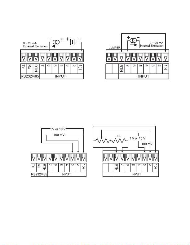
The gure below shows the wiring hookup for Process Current 0 – 20 mA.
Figure 2.11 Process Current Wiring Hookup
(Internal and External Excitation)
When conguring your device, select Process Type in the Input Type Menu
(see Part 3).
2.3.6 Process Voltage
The gure below shows the wiring hookup for Process Voltage 0 – 100 mV,
0 – 1 V, 0 – 10 V.
Figure 2.12 a) Process Voltage b) Process Voltage Wiring
Wiring Hookup with Hookup without Sensor
Sensor Excitation Excitation
RL - Voltage limited resistor, which allows to convert 24 Vdc internal excitation
voltage to the appropriate process input value. For instance: if the potentiometer
value is equal to 10 kΩ, the minimum RL is 14 kΩ for 10 V process input.
When conguring your device, select Process Type in the Input Type Menu
(see Part 3).
12
Page 17
2.3.7 Wiring Outputs
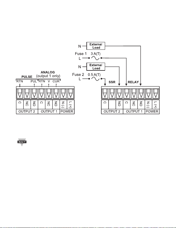
This meter has two factory installed outputs. The SPDT Mechanical Relay, SPST
Solid State Relay and Analog Output Connection are shown below.
Figure 2.13 a) Mechanical Relay b) Analog Output
and SSR Outputs Wiring Hookup
Wiring Hookup
The Fuse has already been connected, it is shown for reference only.
13
Page 18
2.3.7 Wiring Outputs (continued)
Figure 2.14 Typical Applications
Figure 2.15 a) RS232 Output b) RS485 Output
Wiring Hookup Wiring Hookup
14
Page 19
2.3.7 Wiring Outputs (continued)
This device may also have an
excitation output.
Excitation is not available
if communication option
is installed.
This device has snubber
circuits designed to protect
the contacts of the mechanical
relays when it switches to
inductive loads (i.e. solenoids,
relays). These snubbers are
internally connected between
the Common (C) and Normally
Open (NO) relay contacts of
Output 1 and Output 2.
If you have an inductive load
connected between
Common (C) and Normally
Closed (NC) contacts of the
mechanical relays and you want
to protect them from the rush
current during the switching
period, you have to connect an
external snubber circuit between
Common (C) and Normally Closed
(NC) contacts as indicated in
Figure 2.17.
Figure 2.16 Excitation Output
Figure 2.17 Snubber Circuits
Wiring Hookup
15
Page 20

PART 3
OPERATION
3.1 Introduction
The device has two different modes of operation. The rst, Run
Mode, is used to display values for the Process Variable, and to
display or clear Peak and Valley values. The other mode, Menu
Conguration Mode, is used to navigate through the menu options
and congure the device. Part 3 of this manual will explain the Menu
Conguration Mode. For your device to operate properly, the user
must rst “program” or congure the menu options.
Turning your device On for the First Time
The device becomes active as soon as it is connected to a power source. It
has no On or Off switch. The device at first momentarily shows the software
version number, followed by reset
Mode.
Refer to the Main Operator Manual for complete set-up and
programming information.
If you have the Serial Communications Option you can easily
congure the device on your computer or on-line.
, and then proceeds to the Run
RST
16
Page 21

3.1 Introduction (continued)
Table 3.1 Button Function in Conguration Mode
• To enter the Menu, the user must first press a button.
• Use this button to advance/navigate to the next menu item.
The user can navigate through all the top level menus by
a
pressing a.
• While a parameter is being modified, press a to escape
without saving the parameter.
• Press the up b button to scroll through “flashing” selections.
When a numerical value is displayed press this key to increase
value of a parameter that is currently being modified.
• Holding the b button down for approximately 3 seconds will
b
speed up the rate at which the set point value increments.
• In the Run Mode press b causes the display to flash the PEAK
value – press again to return to the Run Mode.
• Press the down c button to go back to a previous Top Level
Menu item.
• Press this button twice to reset the device to the Run Mode.
• When a numerical value is flashing (except set point value) press c
to scroll digits from left to right allowing the user to select the desired
digit to modify.
c
• When a setpoint value is displayed press c to decrease value of a
setpoint that is currently being modified. Holding the c button
down for approximately 3 seconds will speed up the rate at which
the setpoint value is decremented.
• In the Run Mode press c causes the display to flash the VALLEY
value – press again to return to the Run Mode.
• Press the enter d button to access the submenus from a Top Level
Menu item.
• Press d to store a submenu selection or after entering a value —
the display will flash a
d
• To reset flashing Peak or Valley press d.
• In the Run Mode, press d twice to enable Standby Mode with
flashing
Reset: Except for Alarms, modifying any settings of the menu
configuration will reset the device prior to resuming Run Mode.
STBY
.
message to confirm your selection.
STRD
17
Page 22

18
Page 23

OMEGA ENGINEERING, INC. warrants this unit to be free of defects in materials and workmanship for a period of one (1) year
from the date of purchase. In addition to OMEGA’s standard warranty period, OMEGA Engineering will extend the warranty
period for four (4) additional years if the warranty card enclosed with each instrument is returned to OMEGA.
If the unit malfunctions, it must be returned to the factory for evaluation. OMEGA’s Customer Service Department will issue an
Authorized Return (AR) number immediately upon phone or written request. Upon examination by OMEGA, if the unit is found
to be defective, it will be repaired or replaced at no charge. OMEGA’s WARRANTY does not apply to defects resulting from
any action of the purchaser, including but not limited to mishandling, improper interfacing, operation outside of design limits,
improper repair, or unauthorized modification. This WARRANTY is VOID if the unit shows evidence of having been tampered
with or shows evidence of having been damaged as a result of excessive corrosion; or current, heat, moisture or vibration;
improper specification; misapplication; misuse or other operating conditions outside of OMEGA’s control. Components which
wear are not warranted, including but not limited to contact points, fuses, and triacs.
OMEGA is pleased to offer suggestions on the use of its various products. However, OMEGA neither assumes
responsibility for any omissions or errors nor assumes liability for any damages that result from the use of its
products in accordance with information provided by OMEGA, either verbal or written. OMEGA warrants only that
the parts manufactured by it will be as specified and free of defects. OMEGA MAKES NO OTHER WARRANTIES
OR REPRESENTATIONS OF ANY KIND WHATSOEVER, EXPRESS OR IMPLIED, EXCEPT THAT OF TITLE, AND ALL
IMPLIED WARRANTIES INCLUDING ANY WARRANTY OF MERCHANTABILITY AND FITNESS FOR A PARTICULAR
PURPOSE ARE HEREBY DISCLAIMED. LIMITATION OF LIABILITY: The remedies of purchaser set forth herein
are exclusive, and the total liability of OMEGA with respect to this order, whether based on contract, warranty,
negligence, indemnification, strict liability or otherwise, shall not exceed the purchase price of the component upon
which liability is based. In no event shall OMEGA be liable for consequential, incidental or special damages.
CONDITIONS: Equipment sold by OMEGA is not intended to be used, nor shall it be used: (1) as a “Basic Component”
under 10 CFR 21 (NRC), used in or with any nuclear installation or activity; or (2) in medical applications or used on
humans. Should any Product(s) be used in or with any nuclear installation or activity, medical application, used on
humans, or misused in any way, OMEGA assumes no responsibility as set forth in our basic WARRANTY/DISCLAIMER
language, and, additionally, purchaser will indemnify OMEGA and hold OMEGA harmless from any liability or damage
whatsoever arising out of the use of the Product(s) in such a manner.
Direct all warranty and repair requests/inquiries to the OMEGA Customer Service Department. BEFORE RETURNING
ANY PRODUCT(S) TO OMEGA, PURCHASER MUST OBTAIN AN AUTHORIZED RETURN (AR) NUMBER FROM
OMEGA’S CUSTOMER SERVICE DEPARTMENT (IN ORDER TO AVOID PROCESSING DELAYS). The assigned AR
number should then be marked on the outside of the return package and on any correspondence.
The purchaser is responsible for shipping charges, freight, insurance and proper packaging to prevent breakage in transit.
FOR WARRANTY RETURNS, please have the following
information available BEFORE contacting OMEGA:
1. Purchase Order number under which the product was
PURCHASED,
2. Model and serial number of the product under warranty,
and
3. Repair instructions and/or specific problems relative to
the product.
OMEGA’s policy is to make running changes, not model changes, whenever an improvement is possible. This affords our
customers the latest in technology and engineering.
© Copyright 2015 OMEGA ENGINEERING, INC. All rights reserved. This document may not be copied, photocopied,
reproduced, translated, or reduced to any electronic medium or machine-readable form, in whole or in part, without the prior
written consent of OMEGA ENGINEERING, INC.
TRADEMARK NOTICE: ®, omega.com®,
PATENT NOTICE: This product is covered by one or more of the following patents: U.S. Pat. No. Des. 336,895; 5,274,577;
6,243,021 / CANADA 2052599; 2052600 / ITALY 1249456; 1250938 / FRANCE BREVET No. 91 12756 / SPAIN 2039150;
2048066 / UK PATENT No. GB2 249 837; GB2 248 954 / GERMANY DE 41 34398 C2. The “Meter Bezel Design” is a
Trademark of NEWPORT Electronics, Inc. Used under License. Other US and International Patents pending or applied for.
WARRANTY/DISCLAIMER
RETURN REQUESTS/INQUIRIES
FOR NON-WARRANTY REPAIRS,
current repair charges. Have the following information
available BEFORE contacting OMEGA:
1. Purchase Order number to cover the COST of the repair,
2. Model and serial number of product, and
3. Repair instructions and/or specific problems relative to the
product.
, and ® are Trademarks of OMEGA ENGINEERING, INC.
consult OMEGA for
Page 24

M5234/0215
 Loading...