

Page 1
DPG300 SERIES
M-5258/0213
1
Page 2

OMEGAnet Online Service
®
omega.com
Internet e-mail
Servicing North America:
U.S.A: Omega Engineering, Inc., One Omega Drive, P.O. Box 4047
ISO 9001 Certied Stamford, CT 06907-0047 USA
Toll Free: 1-800-826-6342 TEL: (203) 359-1660
FAX: (203) 359-7700 email: [email protected]
Canada: 976 Bergar
Laval (Quebec), Canada H7L 5A1
Toll Free: 1-800-826-6342 (514) 856-6928
FAX: (514) 856-6886 email: [email protected]
For immediate technical or application assistance:
U.S.A and Canada: Sales Service: 1-800-826-6342/1-800-TC-OMEGA®
Customer Service: 1-800-622-2378/1-800-622-BEST®
Engineering Service: 1-800-872-9436/1-800-USA-WHEN®
Mexico: En Español: 001 (203) 359-7803 FAX: (001) 203-359-7807
[email protected] e-mail: [email protected]
Servicing Europe:
Benelux: Managed by the United Kingdom Ofce
France: Managed by the United Kingdom Ofce
Toll-Free: 0800 466 342 TEL: +33 (0) 161 37 29 00
FAX: +33 (0) 130 57 54 27 e-mail: [email protected]
Germany/Austria: Daimlerstrasse 26
D-75392 Deckenpfronn, Germany
Toll-Free: 0 800 6397678 TEL: +49 (0) 7059 9398-0
FAX: +49 (0) 7056 9398-29 e-mail: [email protected]
United Kingdom: OMEGA Engineering Ltd.
ISO 9001 Certied One Omega Drive, River Bend Technology Centre, Northbank
Irlam, Manchester M44 5BD England
Toll-Free: 0800-488-488 TEL: +44 (0)161 777-6611
It is the policy of OMEGA Engineering, Inc. to comply with all worldwide safety and EMC/EMI regulations that apply. OMEGA is
constantly pursuing certication of its products to the European New Approach Directives. OMEGA will add the CE mark to every
appropriate device upon certication.
e information contained in this document is believed to be correct, but OMEGA accepts no liability for any errors it contains, and
reserves the right to alter specications without notice.
WARNING: ese products are not designed for use in, and should not be used for, human applications.
2
Page 3
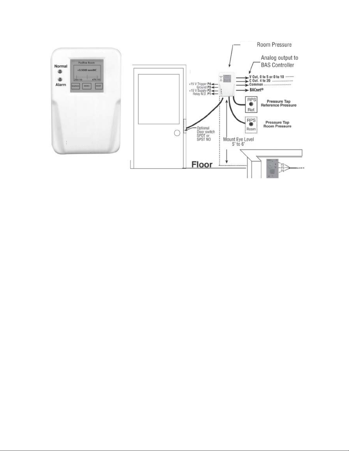
Omega DPG300 Room Pressure Monitor
The Omega DPG300 Room Pressure Monitor is designed for critical low differential
pressure applications that require stringent pressure monitoring and alarming. The
DPG300 can be congured to monitor positive, negative, or neutral pressure in protected environments and hospital isolation rooms per CDC guidelines. The DPG300
is a complete system that includes a backlit RGB LED display with a graphic user interface, which enables access to pressure, security, calibration, and alarm setup. The
touch-screen displays menus that guide the user through setup, as well as setting up
password protection. Red and green LED’s and a local audible alarm (with time delay
feature) alert personnel to system status. The DPG300 has a NEMA 1 (IP20) rated re
retardant plastic housing for indoor applications. True differential pressure is displayed
with a resolution of .0001”. Omega’s patented very low pressure capacitance sensor is
dead ended and avoids the potential for cross contamination of the room and reference
space as well as eliminating drift that results from fouling of ow based on sensors,
which by nature have a ow path connecting the protected and reference spaces. Ad-
ditionally there are 2 levels of password protection available as well as optional BACnet
MSTP communications.
3
Page 4

Table of Contents
1.0 Intended Use
1.1 Specications
1.2 DPG300 Function
2.0 Parts
2.1 DPG300 Included Parts
2.2 (SRAN) Included Parts
2.3 RPS Included Parts
2.4 Parts required and to be supplied by installer
3.0 Installation
3.1 Wiring (Rough In)
3.2 Plumbing
3.3 Wiring (Finish)
3.3.1 Alarm Relay
3.3.2 Remote Annunciator
3.3.3 Door Status Input
3.3.4 Analog Output
3.3.5 BACnet
4.0 Startup and Operations
4.1 Menu Tree
4.2 Power Up
4.3 Monitoring Screen
4.4 Main Menu
4.5 Setup Unit
4.6 Setup Room
4.7 Setup Alarms
4.8 Self Test
4.9 Calibration
4.10 BACnet Setup Screen
5.0 Remote Annunciator
6.0 Maintenance
7.0 Agency Electrical Standards
8.0 Wiring and Plumbing Overview
9.0 Menu Tree
4
Page 5

1.0 INTENDED USE
The DPG300 is designed to monitor critical environments by providing differential pressure indication. Typically this is between a monitored room and a reference space
such as a corridor or ante room. The unit also provides monitoring, alarm and communications functions.
Installation must be indoors, Polution Degree 2, Installation Category II.
Typical Applications:
1. Hospitals: patient isolation and protection rooms, operating suites, intensive
care, and emergency rooms.
2. Pharmaceutical, semiconductor, precision manufacturing, and clean rooms.
3. Laboratories: medical research, BSL (Bio safety labs), radiation, vivarium,
toxic metals and chemicals. Indoor use only.
1.1 SPECIFICATIONS
Service: Air or nonconductive, nonexplosive gases.
Accuracy: ±0.5% F.S., ±0.25% FS optional
Operating Temperature Limits: 32 to 120°F (0 to 50°C).
Operating Humidity Limits: 5 to 95% Relative humidity (non-condensing).
Altitude: 2000 meters (max).
Thermal Effects: ±0.03% F.S./ °F (± 0.05% F.S./ °C).
Overpressure: ±15” WC.
Supply Voltage:
Code V1 and V2 85-265 VAC, 50-60 Hz
Code A1 and A2 18-32 VAC, 50-60 Hz.
Power Consumption (Voltage output): 5 W.
Output: Selectable 4-20 mA (2-wire), 0-5 VDC (3-wire), or 0-10 VDC (3-wire).
Loop Resistance (4-20mA output): 0-510 OHMS Ω.
Electrical Connection: Removable terminal block.
Pressure Fittings: Barbed ttings for 1/4” O.D. tubing.
Housing: Fire retardant plastic (NEMA 1, IP20 rated for indoor applications).
Mounting: Mounts to customer supplied 4½ x 4½ plaster ring (mounts to double gang
electrical box).
Dimensions: 8½ H x 5.4½ W x 1.8½ D (20.3 H x 13.7 W x 4.1
Weight approx.: 1.5 lbs (680 g).
Agency Approval: CE, CAN/CSA-C22.2 NO. 61010-1-04
Communications: BACnet MSTP ASC, optional, see omega.com for detailed PICS
statement.
5
Page 6

1.2 DPG300 FUNCTION
The DPG300 senses very low differential pressure using high accuracy capacitive sensor technology. The pressure difference for these applications is the difference in static
pressure between a critical environment room and its surrounding reference area (usually a hallway or another room). Maintaining and monitoring a static room pressure
difference ensures that the critical environment room is either protected or isolated
from a surrounding environment. Protection strategy requires a net positive room static
pressure difference, while isolation requires a net negative static pressure difference.
The DPG300 can be programmed to monitor either positive or negative room static
pressure. Low pressure sensing technology is coupled with multifunctional alarming
and simple touchscreen user interface with password security protection. The BACnet
communication option allows the device to communicate with other BACnet devices to
allow the supervisory system to change conguration setups and monitor alarms in an
open network.
User Interface: LCD Display 128 x 128 COG module, with custom RGB LED backlight
and custom 4-wire resistive touch screen.
RGB Backlight: The DPG300 indicates the status of the room being monitored using
visual backlight color.
Color Status
Green Room Pressure is within alarm limits
Yellow Door is open. (Door input must be enabled)
Red Room Pressure is outside alarm limits and alarm
delay period has been exceeded and room is not
in “No Isolation” mode.
Visual Feedback: LED’s, green for normal, red for alarm
Audible Feedback: Beeper will sound when pressure is out of range and alarm delay
has timed out. Volume can be adjusted between 1 to 4 in relative sound levels up to
the maximum level specication of t he beeper to 85 dB at 4”. Audible alarm can also
be disabled.
Quick Room Mode Change: Sometimes the room needs to be changed quickly from
in use (Occupied) to out of use (No Isolation). This is accomplished by using 2 levels
of password protection. The Operator level allows access to change room modes but
no other changes. The Supervisor level allows full access to all menus. In No Isolation
mode no alarms are generated even if the pressure is outside limits. To change mode,
see page 23, Room Mode Change, for directions to change modes.
6
Page 7
2.0 PARTS
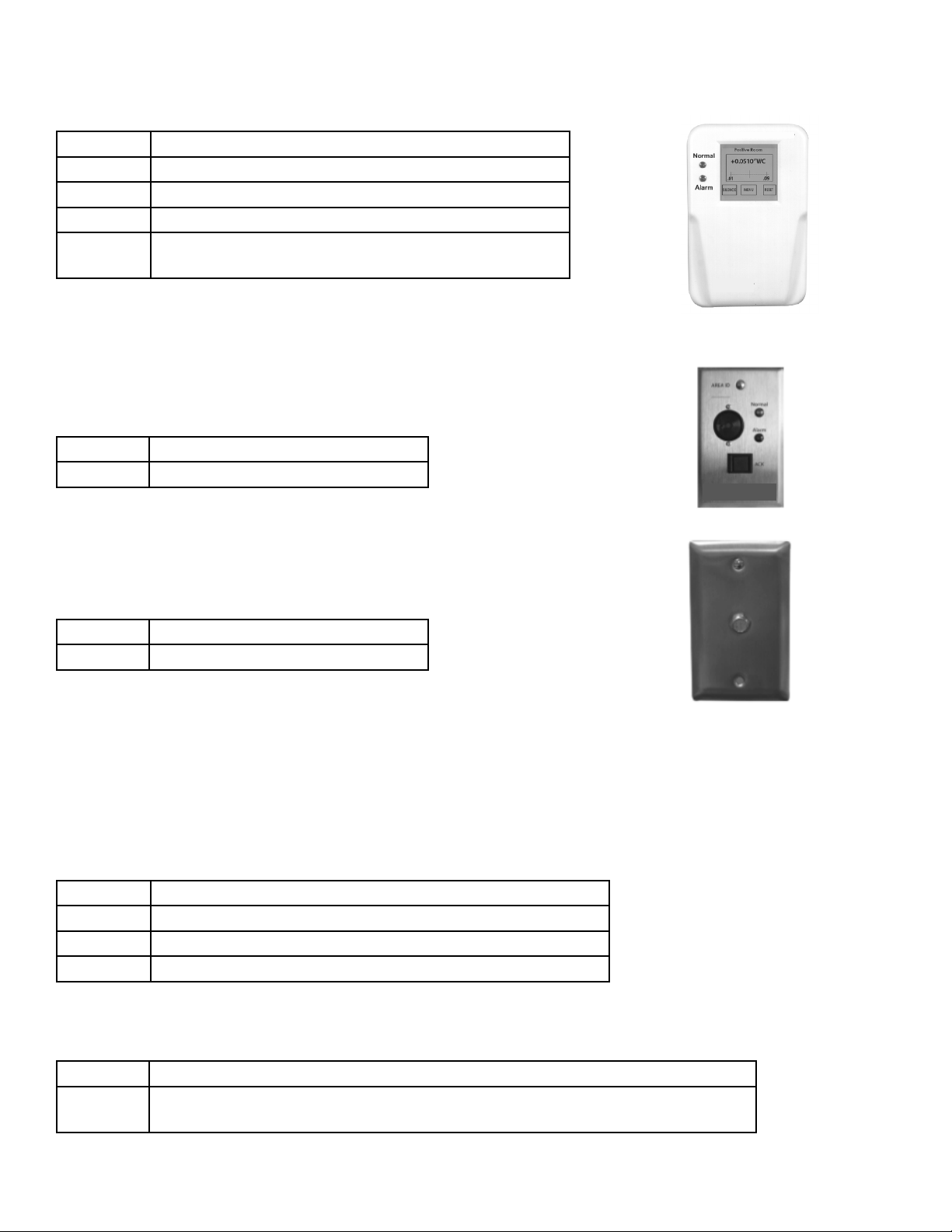
2.1 DPG300 Room Pressure Monitor) INCLUDED PARTS
Quantity
1 DPG300 assembly
2 Barbed Couplings, Brass, Plated
2 1/4 inch Tubes, Silicone
4 6-32 x 1/2” Mounting Screws for connecting DPG300
Base to the plaster ring
2.2 Remote Annunciator INCLUDED PARTS
Quantity
1 Annunciator Assembly
2.3 Room Pressure Snubber INCLUDED PARTS
Quantity
1 Room pressure snubber Assembly
MOUNTING AND WIRING
To mount and install properly, the following components are required:
NOT INCLUDED and required for each DPG300
Quantity
1 Double Gang Metal Electrical Box with Grounding Stud
1 4x4 inch Metal Plaster Ring
1 Door Switch SPDT or SPST, N.O., as needed
NOT INCLUDED and required for each remote annunciator & room pressure
snubber:
Quantity
1 Single Gang Electrical Box
1/4” tubing as required to connect between the Annunciator and the DPG300
7
Page 8
3.0 INSTALLATION (See Section 8.0 for Overview)
For 120/240 VAC Version, only
CAUTION: Do not open or remove DPG300 cover (tool required) with input power applied unless
performed by a licensed electrician. “Hazardous Live” voltage is present at connector J3 when power
is applied. Please observe the warning symbol ( ) near the J3 power connector.
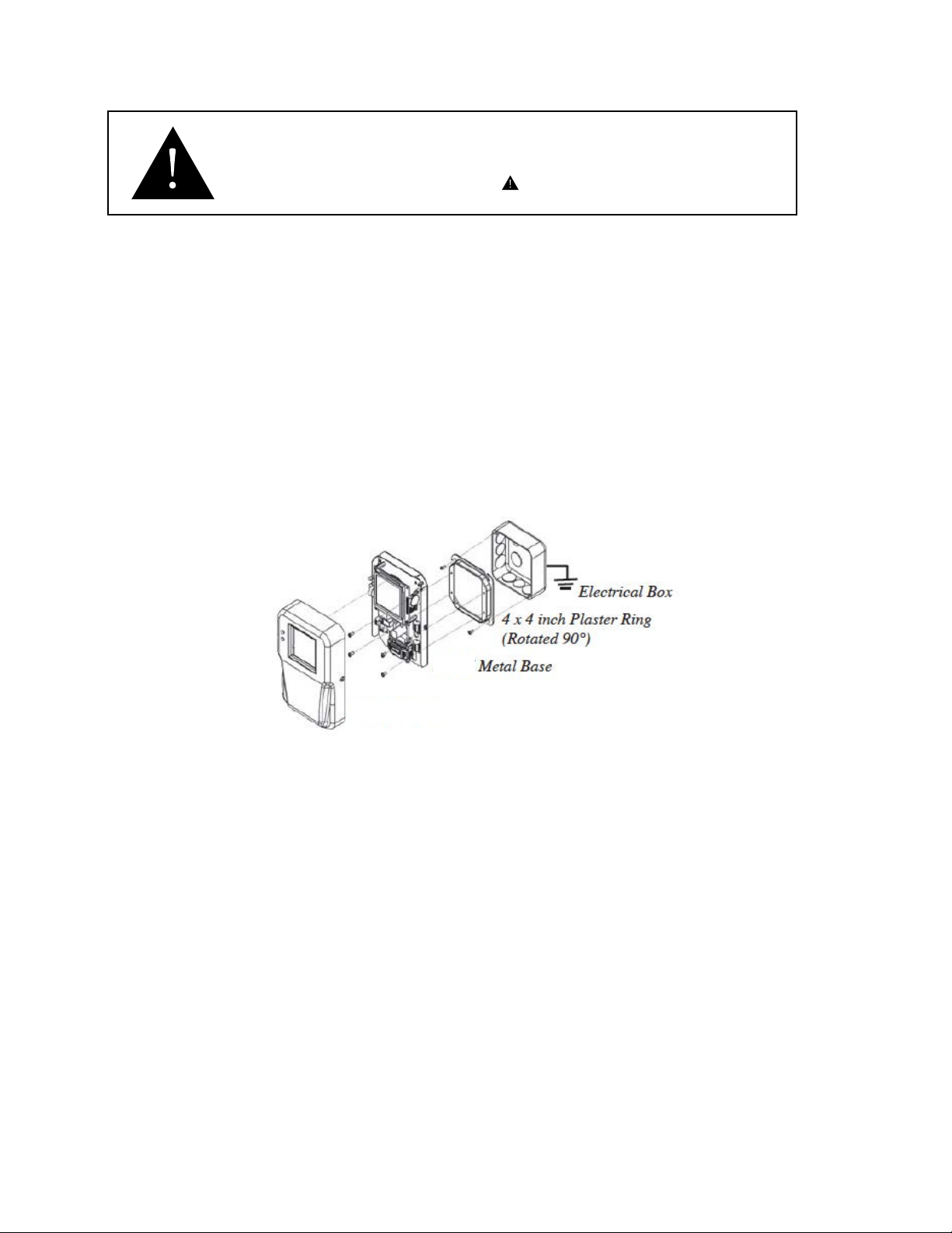
The DPG300 is designed to be mounted on a standard double gang metal electrical
box using a 4 x 4 inch plaster ring adaptor. After the rough in wiring and plumbing is
performed, remove the cover and mount the baseplate to the plaster ring adaptor using
the supplied 6-32 x 1/2” long mounting screws. Note: The plaster ring external mount-
ing face needs to be positioned ush to recessed, relative to the surface of the wall.
Also note the orientation of the 4 mounting screws in the plaster ring, as the plaster
ring is rotated 90° from conventional mounting.
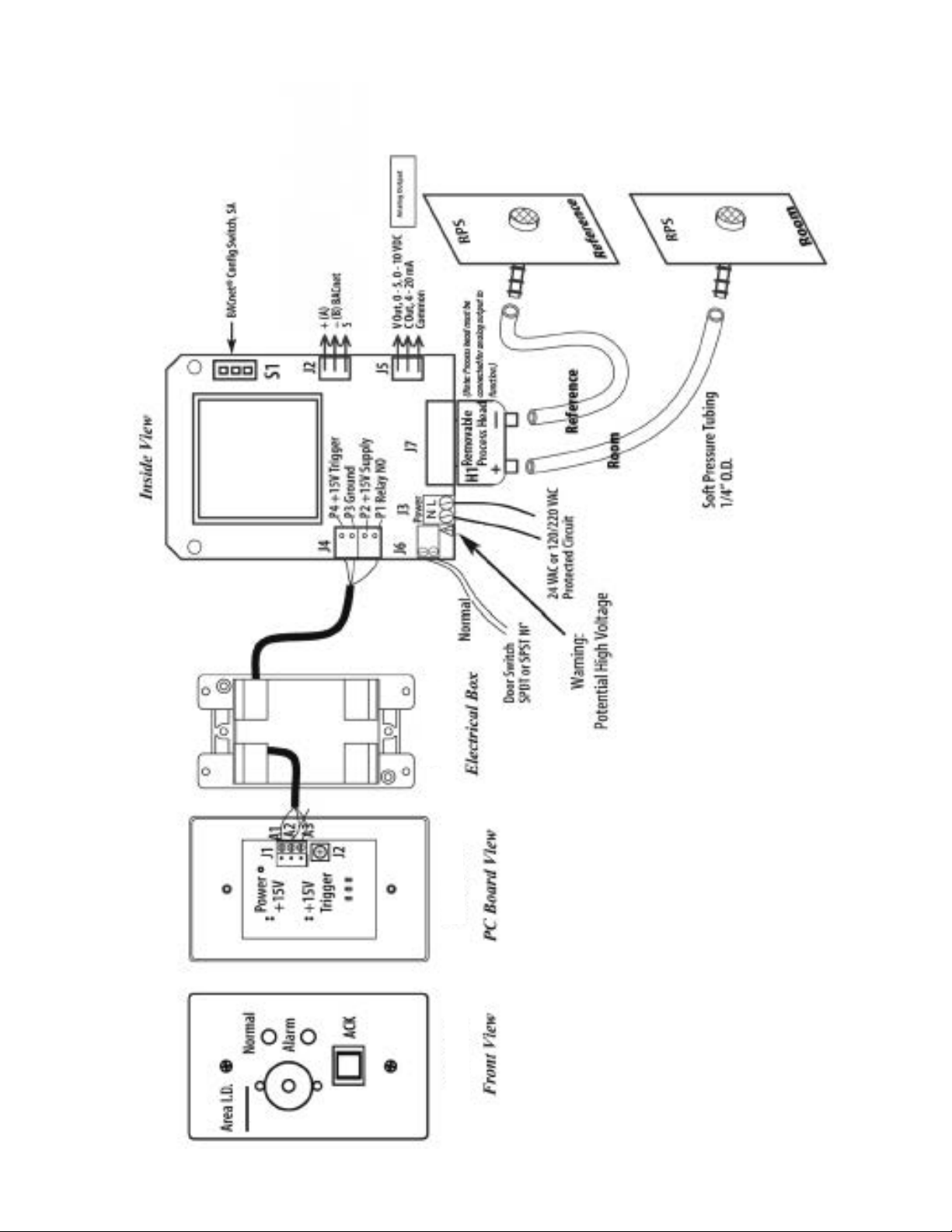
Note: In the following wiring sections, abbreviations are used (e.g. J1, P3). Please see
section 8.0 for complete wiring diagrams with abbreviations.
3.1 WIRING ELECTRICAL BOX (ROUGH IN)
Layout the system in terms of wiring: power, annunciator, analog output, BACnet, relay
output and plumbing to connect to the monitored spaces (pressure taps).
Bring all power, earth ground, signal, communications and analog output wiring into the
4 x 4 electrical box.
Bring 1/4” O.D. tubing for 3/6” Barb tting into box.
In order to conform to the CSA safety standard the electrical installer must comply with
the following earth ground instructions. Pre-wire the electrical box with power (24 VAC
or 120/240), and provide earth grounding to the electrical box. The safety ground path
consists of four 6-32 x 1/2” metal screws that connect the DPG300 metal base to the
4½ x 4½ metal plaster ring. The plaster ring must be grounded to the 4½ x 4½ electrical box by 2 metal mounting screws. The 4½ x 4½ electrical box must be connected to
the building earth ground. It is also highly recommended to use armored cable (Type
AC) for all the wiring in applications where high levels of radio interference may be
present.
Power leads, analog output, door status, and annunciator wiring should be 14 to 22
8
Page 9

AWG stranded wire.
BACnet suggested wiring is 22 AWG stranded wire in a shielded cable, a +,-, Gnd (S)
and shield should be run. This could be 2 twisted pairs with a separate shield. One
twisted pair is used for communications, the second twisted pair can be connected to
the other device shield wires.
9
Page 10
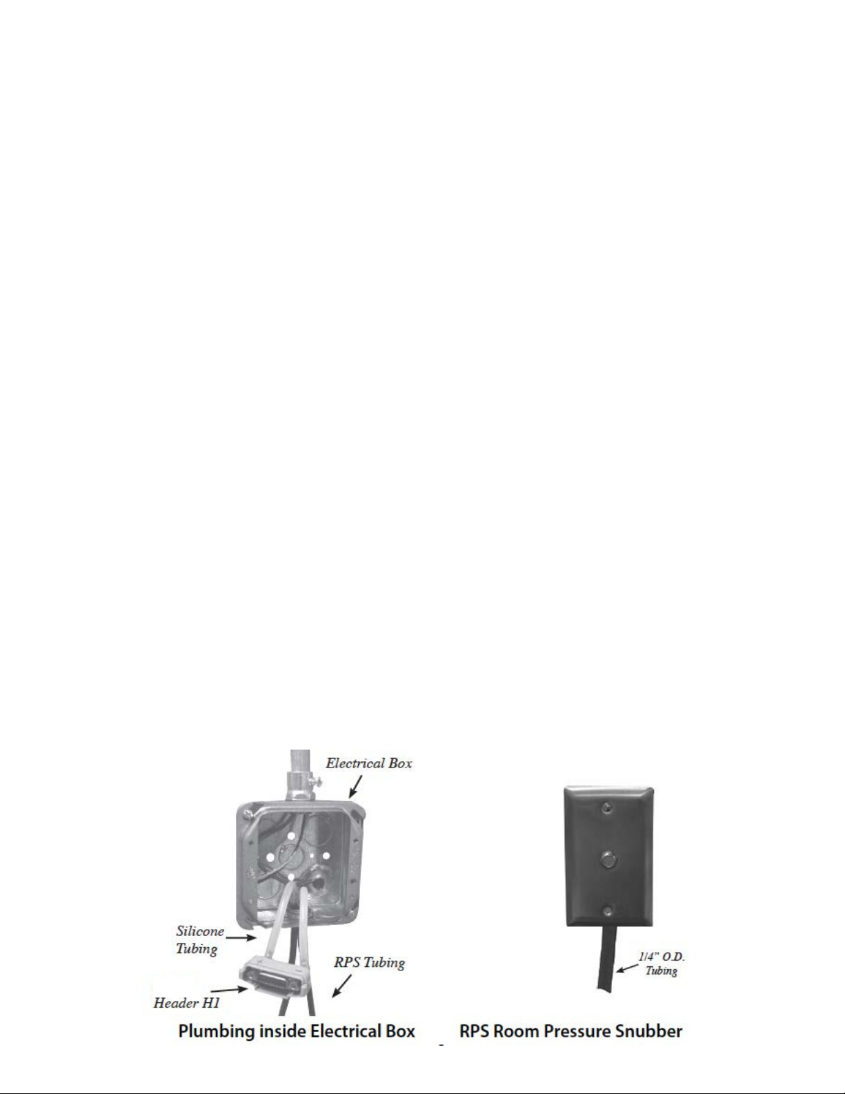
3.2 PLUMBING (ATTACHING PRESSURE TUBING)
Warning: Always attach tubing to the DPG300 header and then place Header
onto DPG300. This will prevent overpressure from crimped or collapsed tubes.
Use the following procedure for all room types: positive, negative or neutral:
Typically a Room Pressure Snubber (RPS) is installed in the monitored room. Often
stiff nylon ¼” tubing is used for running pressure signals from the DPG300 to the monitored spaces. To prevent buckling and collapse of this stiff tubing inside the electrical
box, use the supplied soft silicone tubing and tubing adaptors to transition from the eld
tubing to the pressure ttings on the DPG300.
Attach pressure tubing as follows:
1. Connect the 1/4 inch O. D. tubing running from the RPS (or other pressure connection from the monitored space) to the 4½ x 4½ electrical box for the DPG300. Install
one of the supplied 1/4 inch male to male barbed tube adaptors onto the end of the
tube then push the 4” length silicone tube (supplied) onto the other end. Thread the
tubes, with installed adaptor, through the conduit opening at the bottom of the electrical
box.
2. Next push the open end of the silicone tubing onto the DPG300 pressure tube header (H1) port labeled “+”. Note: The header is an Electro-Pneumatic (EP) assembly. “+”
indicates (Positive) pressure, and “-” indicates negative or reference pressure.
3. For the most pressure stable operation, an RPS installed in the reference pressure area is also recommended. In this case, install the RPS in a hallway or reference
space. Attach the tube to the DPG300 in the same way as for the + port, except at-
tach the tube to the “-” port on the pressure tube header. Tighten swivel ttings on the
DPG300 Header H1 assembly if they become loose, 9 in lb. max. Verify that the tubes
are not buckled, which could close off pressure signal at end of installation.
10
Page 11
3.3 WIRING, FINISH
3.3.1 ALARM READY OUTPUT
The single Pole Single Throw (SPST) relay output can be used for remote signaling of
alarm condition. A form “C” contact rated 1A is available. Connect to J4, P1 and P4
(See Section 8.0 for Diagram of J4). This relay can be used as a dry contact for remote indication or can drive a remote annunciator.
3.3.2 OPTIONAL REMOTE ANNUNCIATOR
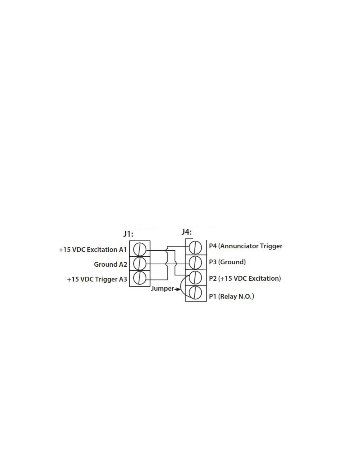
In the gure below, the remote annunciator connector is at left, and the DPG300 connector is at right:
On J4 of the DPG300, jumper P1 to P2, this will connect the internal 15V supply to the
common of the internal alarm relay. Connect P2 to A1 (Located on Remote Annunciator), this supplies 15V exc. to the Annunciator for powering the circuit during normal
conditions. Connect P3 of J4 to A2 of the remote annunciator J1, this is the 15V power
return. Finally connect P4 of the DPG300 J4 to A3 terminal of the remote annunciator
J1, this is the alarm trigger. When as alarm occurs and after the programmed alarm
delay times out the internal relay will supply 15V to the Annunciator circuit to actuate
the audible beeper and the red LED.
Annunciator
DPG300
Non-Omega Remote Annunciator
The DPG300 can drive other annunciators that are powered by a 15V supply, 50mA
max current draw., and accept a 15V trigger (wire as above).
11
Page 12
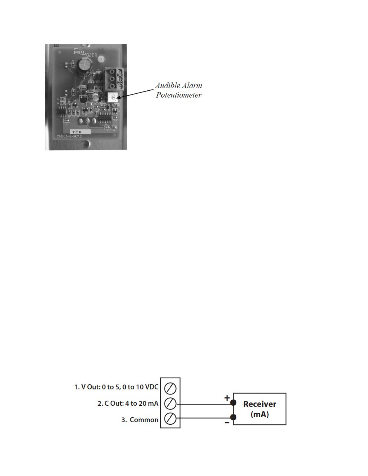
The volume control of the Annunciator is a potentiometer that can be adjusted from 0 to
85 dB. Using a small at bladed screwdriver, rotate potentiometer (remote annunciator
PC board) clockwise to increase volume and counterclockwise to decrease volume.
3.3.3 DOOR STATUS SWITCH WIRING
Install the door switch into the door jamb. Wire to the normally open (N.O.) side of the
door jamb contact switch. The DPG300 will indicate the status of the door position. A
contact closure indicates that the door is closed. This is a low voltage circuit (5 VDC).
Run 2 wires from the door switch to connector J6 on the DPG300 (See Section 8.0).
The door input status function is enabled in the SETUP ALARMS menu screen, section
4.7.
3.3.4 ANALOG OUTPUT
The DPG300 can be congured to have either current (4 to 20mA) or voltage (0 to 5
or 0 to 10 VDC) outputs. Voltage output--pin 1, Current output--pin 2, Common--pin 3.
Note: No external excitation if required.
Current Output
The DPG300 supplies it’s own loop power, do not wire in a separate power supply.
12
Page 13
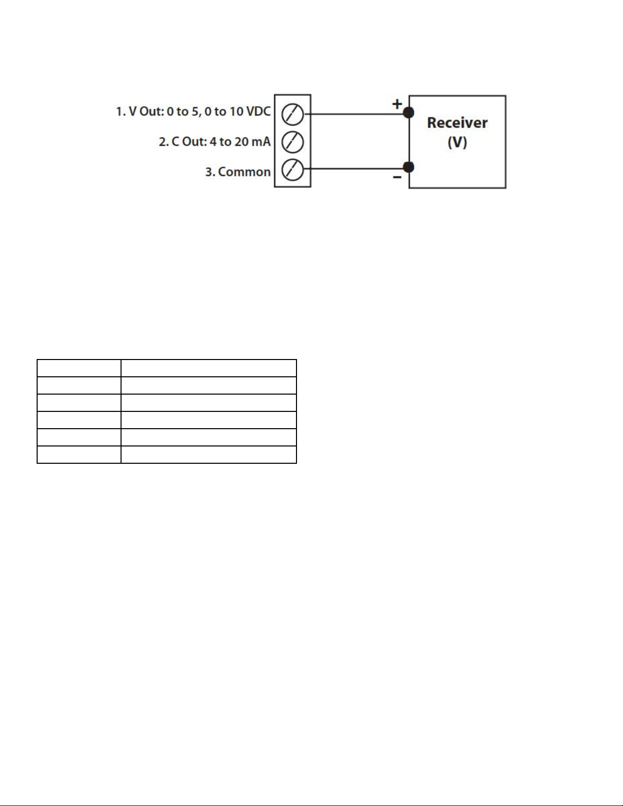
Voltage Output
3.3.5 BACnet
BACnet hardware is implemented as isolated RS485. Wire to Connector J2, labeled
RS-485. Connect tx line to +(A), rx to -(B) and ground wires to S. Connect Shields
together with wire nut.
Hardware conguration is done using a 5 position dip switch (S1) located int he upper
right hand section of the PCBA as well as through the touch screen interface, see section 4.4 and 4.9.
Position Function
1 MAC address enable
2 N/C Not Connected
3 Pull Up Resistor
4 Termination Resistor
5 Pull Down Resistor
Use a small at blade screwdriver or pen to push the switch to the right to turn that
function on, otherwise it is off.
There is a BACnet setup screen that is enabled by pushing position 1 switch to the “on”
position. After conguration the switch must be moved to the “off” position.
13
Page 14
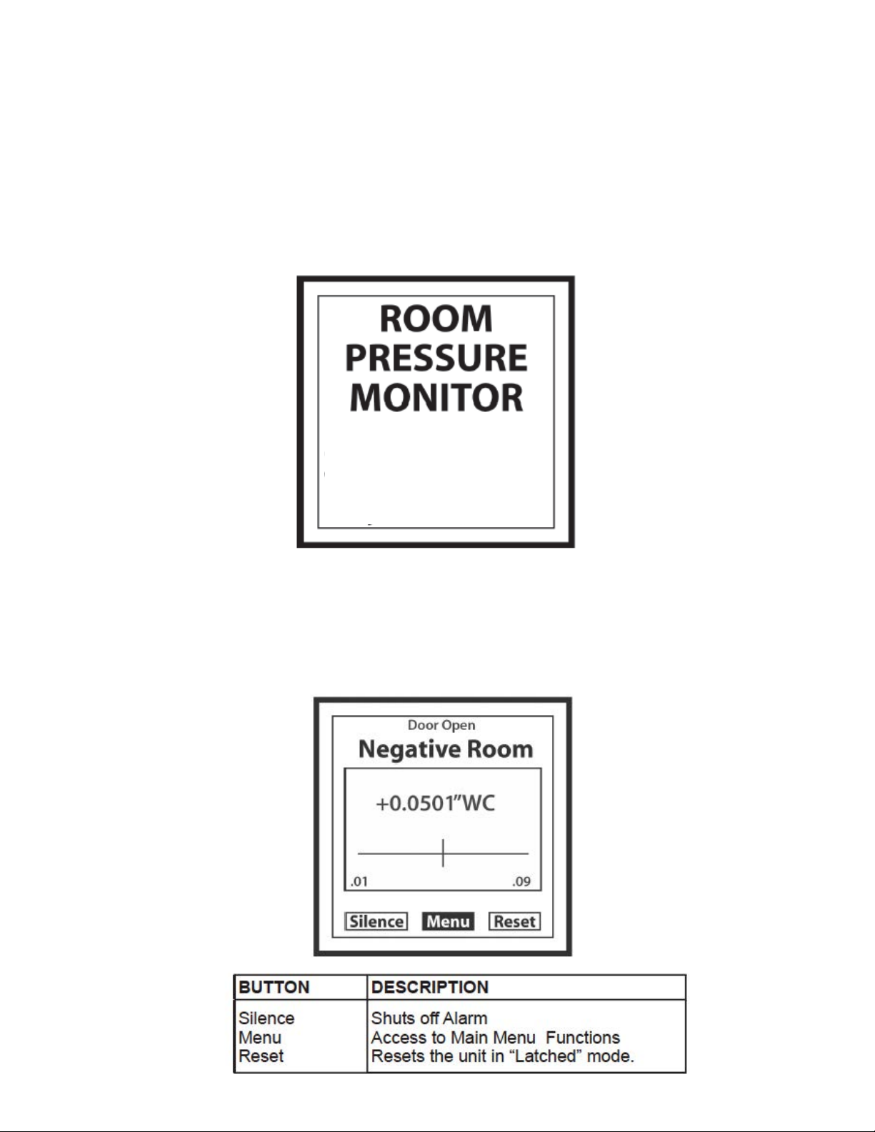
4.0 STARTUP AND OPERATION
The DPG300 is designed with as an easy to use, intuitive, touch screen interface. In
its normal (default) state the Monitoring Screen displays the actual room static pressure, also a slider bar shows the actual pressure relative to the alarm limits. The RGB
backlight is used to indicate the condition of the room. The buttons at the bottom of the
screen give you access to the functions that can be performed.
4.1 MENU TREE
4.2 POWER-UP
Apply power and observe the welcome screen and subsequent transition to the pressure monitor screen. The actual room static pressure is shown as a number in the
center of the LCD screen and visually as a moving bar indicator operating between the
preset alarm units. The vertical bar is an indicator of the pressure
4.3 MONITORING SCREEN
14
Page 15
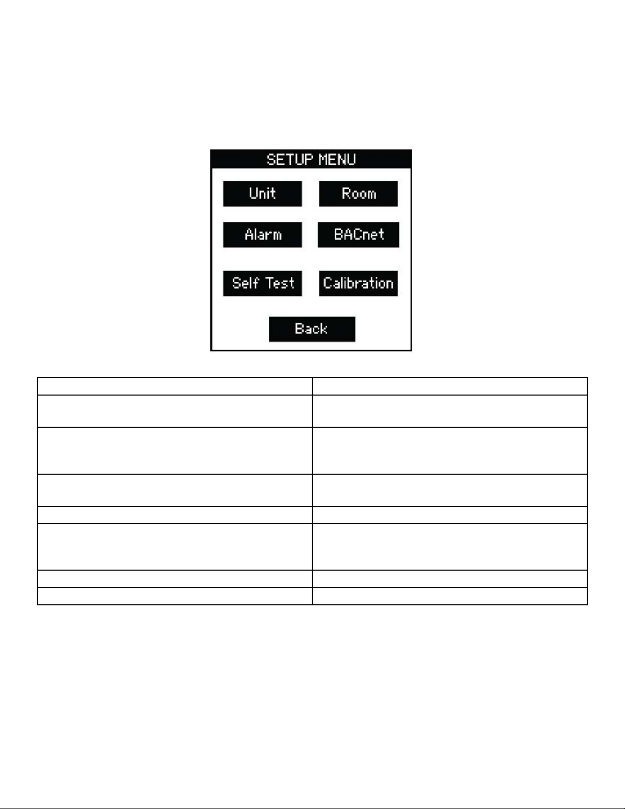
The following screens are conguration screens, they can be congured so that Password protection is required to make changes. If no entry is made to the screen the unit
will return to the default screen after approximately 1 minute.
4.4 MAIN MENU SCREEN
BUTTON DESCRIPTION
Unit Setup Supervisor password, output, engineering
units, and display averaging.
Room Set up high and low pressure limits to monitor
a positive, negative, or neutral room. Operator
password setup.
Alarm Setup latch alarm, audible alarm, door alarm
input, mute time out, alarm delay, and volume.
BACnet Conguration of BACnet Communications
Self Test Identies product model and software version,
and serial #.
Veries memory and performs alarm test.
Calibration Perform zero and span calibration.
Back Returns to monitoring screen.
15
Page 16
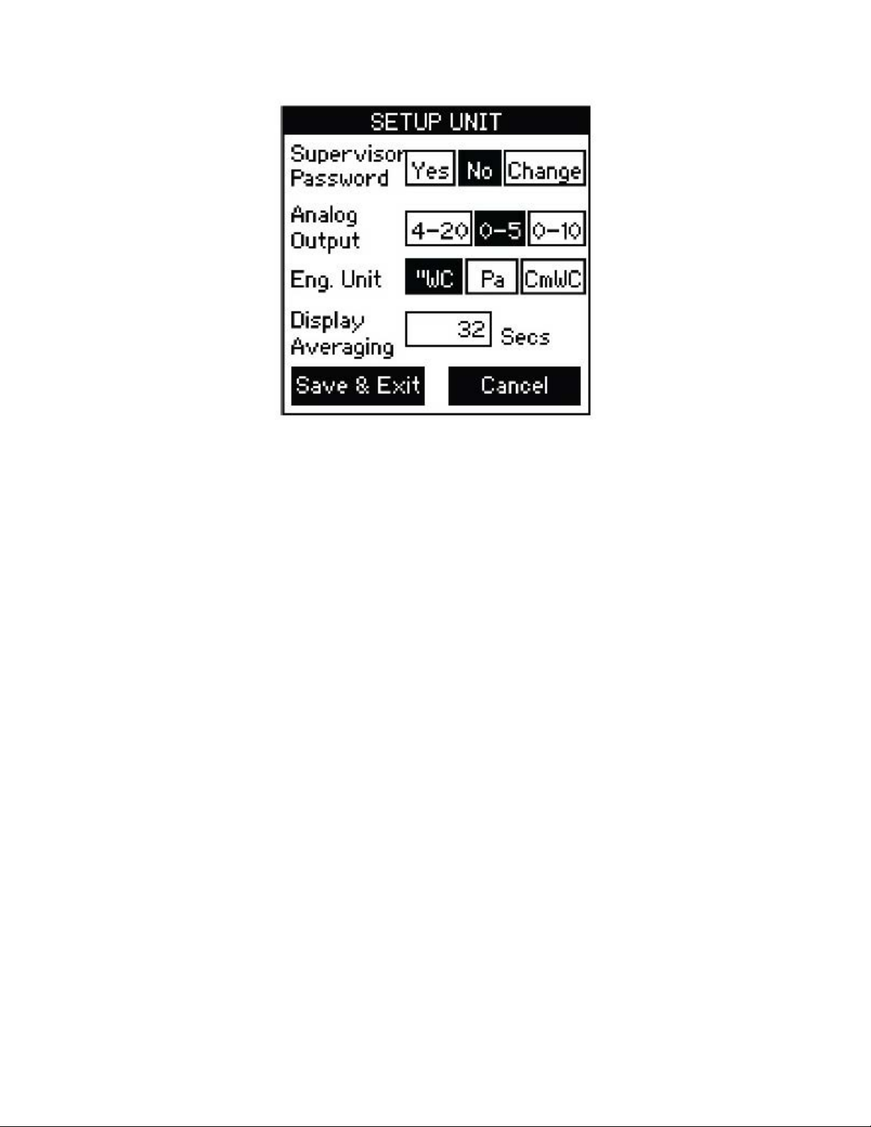
4.5 SETUP UNIT OPERATION
ENTERING DATA:
Press (or tap) button to select an output or engineering unit. Selected button background will change from clear to black.
PASSWORD PROTECTION:
Lightly pressing (or tapping) the “Yes” button activates Supervisor password protection.
With Supervisor password protection enabled, operators can not access menu screens
to update setup. Pressing “No” disables password protection. Pressing “Change” will
open “Password Setting Screen”. To change the password, enter the present password (numeric value), followed by the new password in the “New Password” and “Con-
rm New Password” entry boxes, then press save. Be careful to store password for
future reference.
Analog Output:
Select 4-20, 0-1, or 0-10
Eng. Unit:
Select WC, Pa, or CmWC
DISPLAY AVERAGING:
Lightly pressing (or tapping) the “Display Averaging” box activates the “Data Entry
Screen”. Enter from 0 to 60 seconds. Display averaging affects the analog output.
Increase the display averaging time to smooth out the pressure readings, this will also
reduce the display update rate. Press Save and Exit.
16
Page 17
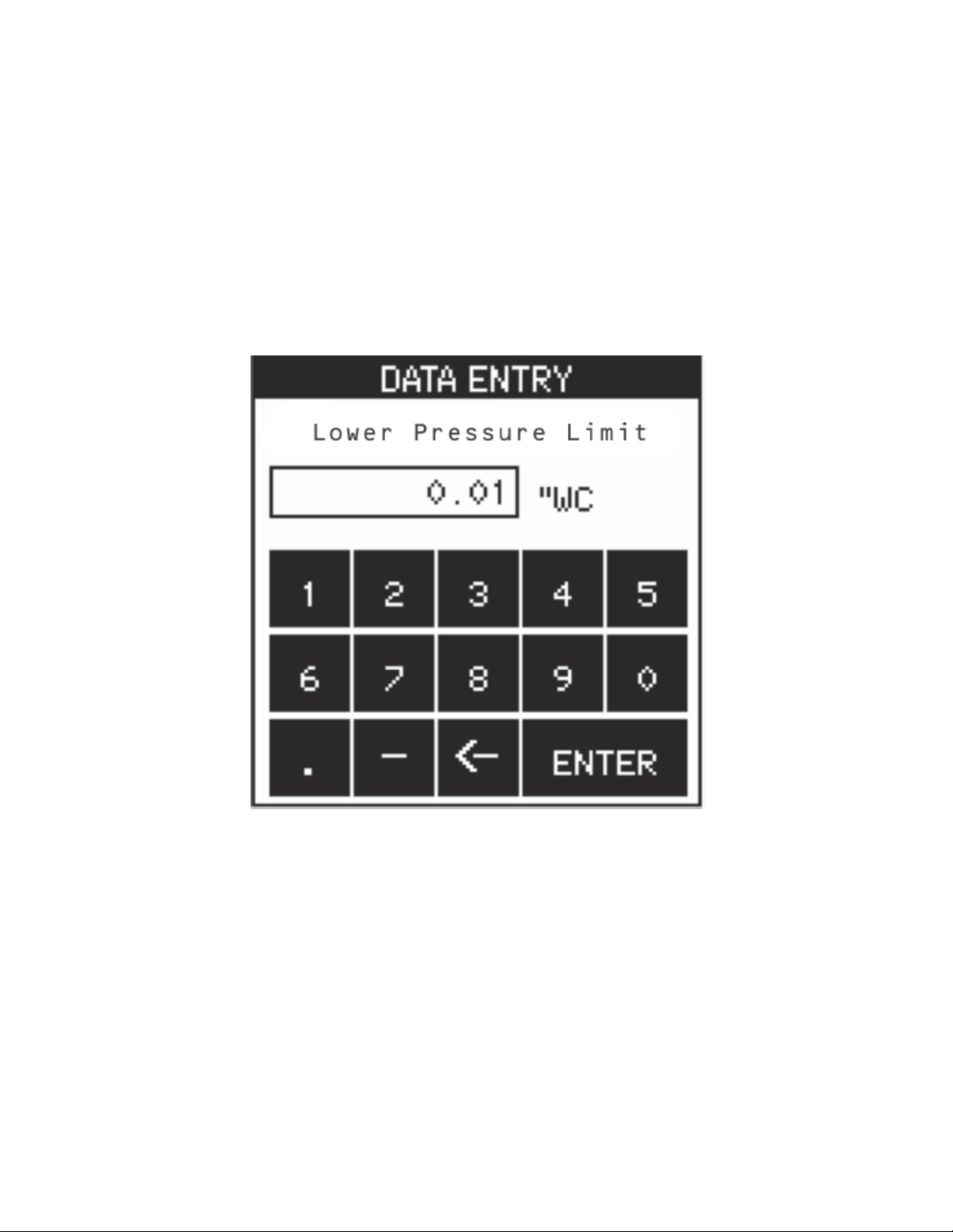
DATA ENTRY SCREEN
Enter numbers by pressing each key in sequence until the desired character is displayed in the data entry box above the keypad. (Note: The cursor will blink for one to
two seconds then stop and display the character.) Erase any mistakes by using the
“Back Space” key. When nished entering data, press the “Enter” key to return to SETUP UNIT screen.
Note: Use the erased end of a pencil or back-end of a pen to press (or tap) box on
screen to increase accuracy of inputs.
17
Page 18
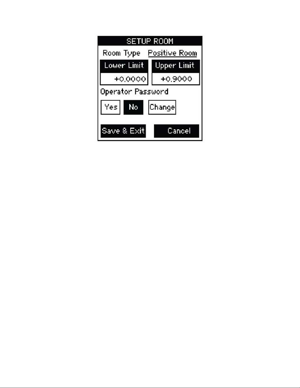
4.6 SETUP ROOM SCREEN
SETUP ROOM OPERATION
Setup alarm limits for “protective” positive room static pressure “isolating” negative
room static pressure or neutral (where the limits can be - to +).
ENTERING DATA
Press lightly or tap in the Lower Limit data entry box. Enter the lower limit pressure.
Enter the Upper Limit pressure. The Room type box will change depending on the
lower and upper limits. If both entries are positive, the room will be a Positive Room. If
both are negative, the room will be a Negative Room and if the Lower Limit is negative
and the Upper Limit is positive, the room will be a Neutral Room.
OPERATOR PASSWORD
The operator can only change the room from Occupied to No Isolation and vice versa.
Lightly pressing (or tapping) the “Yes” button activates the Operator password protection. With Operator password protection enabled, room Occupied/No Isolation status
can be changed without entering a valid Operator password. Pressing “No” disables
password protection. Pressing “Change” will open “Password Setting Screen”. To
change the password, enter the present password, followed by the new password in
the “New Password” and “Conrm New Password” entry boxes, then press save. Be
careful to save the operator password for future reference.
18
Page 19
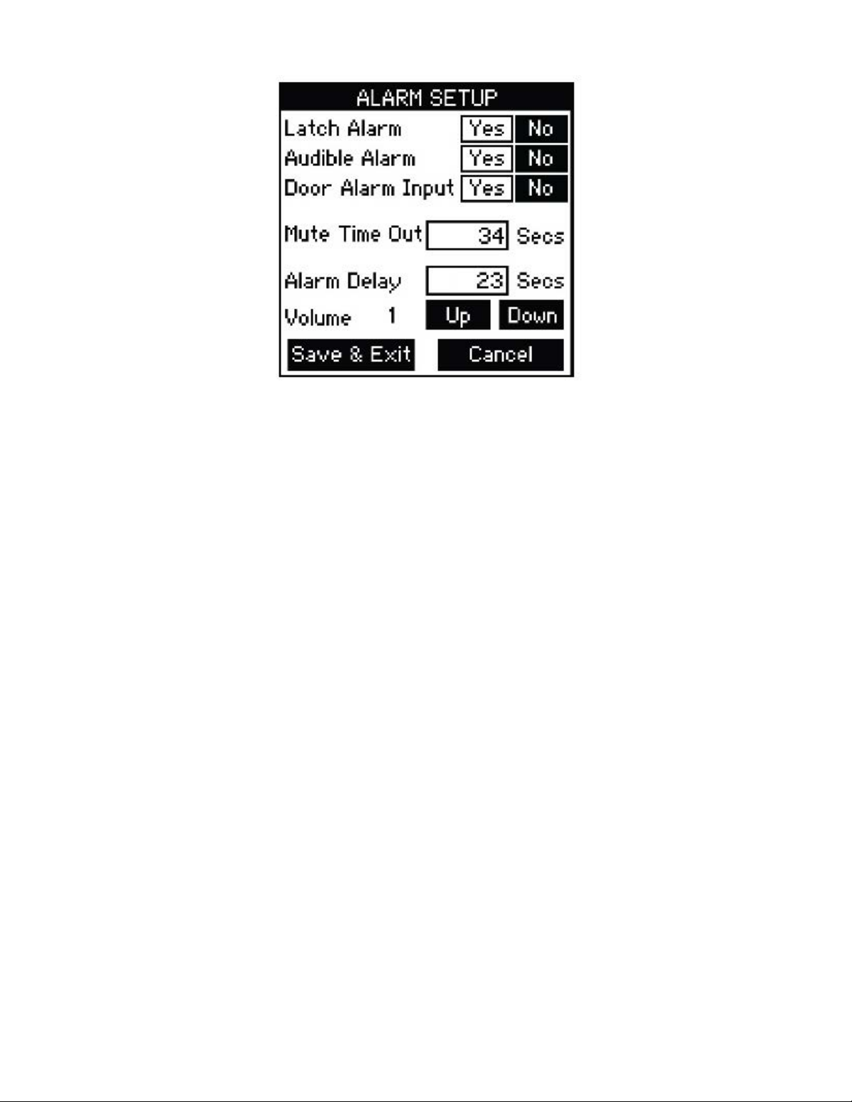
4.7 SETUP ALARMS SCREEN
From this screen the user can access the following:
a. Latched Alarm requires the pressure to return to normal and the alarm to be
acknowledged before the alarm can be silenced and reset.
b. Enable the audible alarm by selecting “Yes” or use visual only alarm by selecting
“No”
c. Provide a “door open” warning visual indication. When a door jamb contact
switch is used and this button is activated by pressing “Yes”, the door status
“open” condition is indicated by the touch screen display turning from green
to yellow, and the door indicated on the monitoring (default) screen.
d. Set the time (in seconds) that the alarm can be silenced in the latched alarm
mode before the alarm resumes. This assumes that the room static pressure is
still outside the normal or set operating limits. The Mute Time Out can be
set from 0 to 9999 seconds.
e. Set the Alarm Delay (in seconds) from the time that the room pressure goes out
of the preset limits until the alarm activates. The alarm delay may be set from 0
to 9999 seconds.
f. Set the alarm volume or sound level. Using the Up and Down keys, the volume
can be set at level 1-4. Level 4 alarm volume is the loudest and corresponds to a
sound level of 85 dB at a distance of 4 inches.
ALARM SETUP OPERATION
Lightly press (or tap) button to select “Yes” or “No” for Latch Alarm, Audible Alarm, or
Door Alarm Inputs. Selected box background will change from clear to black when
selected.
MUTE TIME OUT/ALARM DELAY
Pressing (or tapping) the “Mute Time Out” or “Alarm Delay” box activates the Data Entry screen to set the time delay duration.
19
Page 20
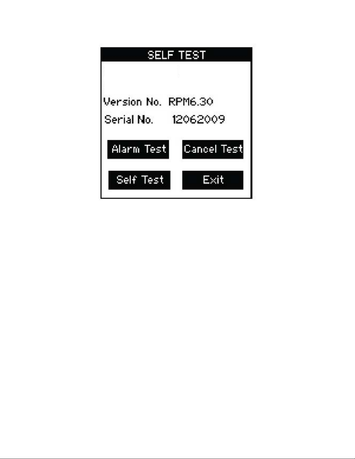
4.8 SELF TEST SCREEN
Self Test Operation
This screen identies the Product Model Part Number and Software Version. User
can also perform a Self Test of the unit to verify that the data is in protected area of the
EEPROM memory hasn’t been corrupted and also test the alarm to verify the sound
level and alarm setup.
Press “Self Test” button to initiate EEPROM memory checksum test sequence.
Press “Alarm Test” to test beeper, visual Red LED Alarm, and relay output. This can be
used to verify the system in alarm mode.
Press “Cancel Test” to stop the alarm test.
Pres “Exit” to return to Main Menu.
20
Page 21
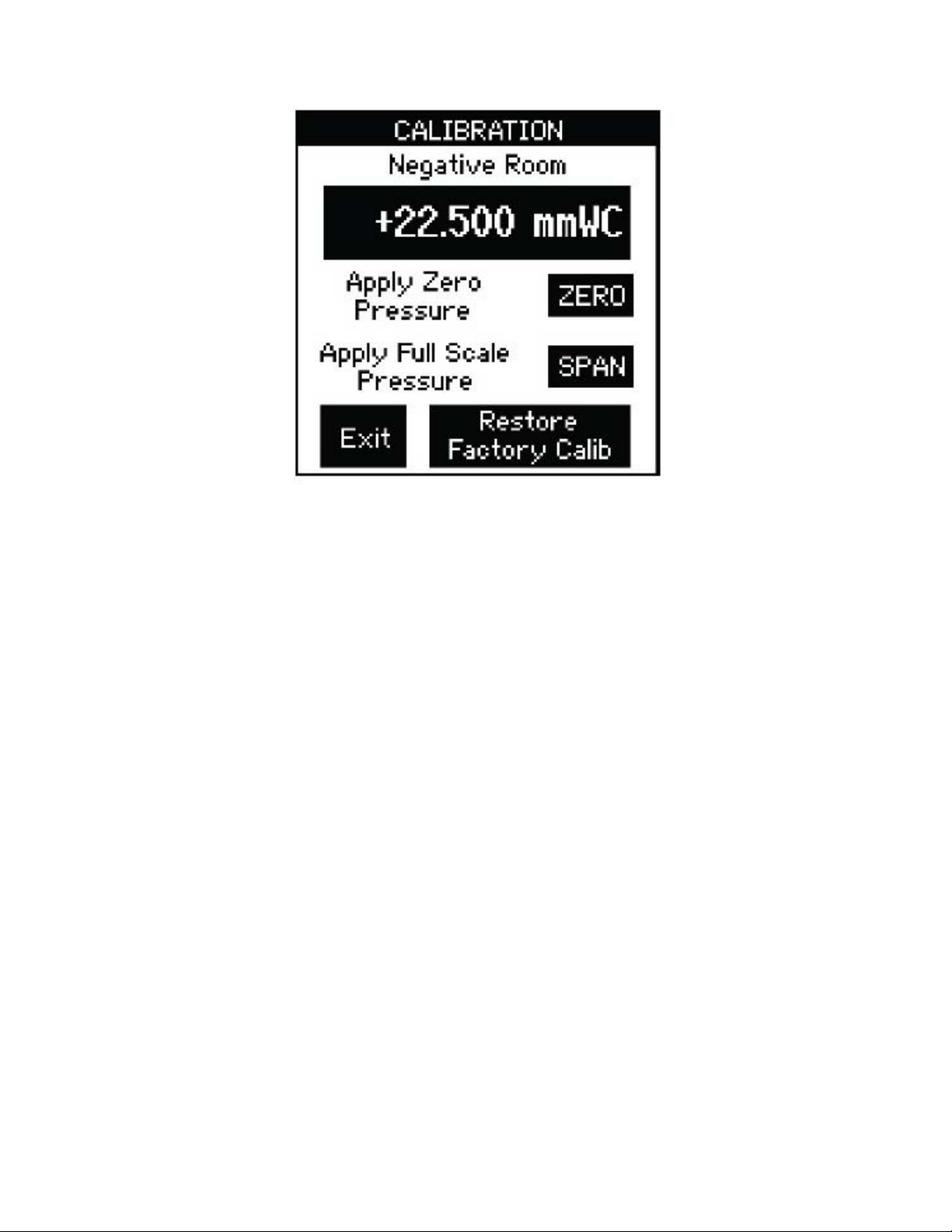
4.9 CALIBRATION SCREEN
CALIBRATION
To re-zero the device, disconnect the electropneumatic Header H1 so that room pressures are not applied to the pressure sensor and lightly press (or tap) the “Zero” button.
If a sufciency accurate Pressure Calibrator is available, apply a stead full-scale pressure signal to the “+” on the header tting and press (or tap) the “Span” button. Recon-
nect the room pressure tube and calibration is complete. Calibration must be within
±5% of original calibration for this to occur otherwise an error message will occur.
The original factory pressure calibration can be restored, if desired, by pushing the
“Restore Factory Setting” button.
21
Page 22
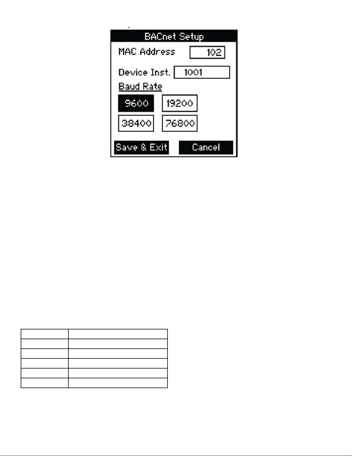
4.10 BACnet Setup Screen
BACnet Setup
• To setup BACnet communications, the MAC address enable switch (S1 [See Section 8]) on the dip switch must be enabled by pushing it to the right.
• Set MAC address, input the address of the device.
• Select Device Instance by inputting the device instance into the data entry box.
• Select baud rate by pressing the correct baud rate button, 9600 to 76800.
• Save and Exit to save settings or Cancel to cancel setting changes. Once complete
disable the BACnet setup by moving the dip switch position 1 to “off” (left) position.
• If the unit will be at the end of the line, the pull resistor can be enabled by pushing
position 3 to “on”.
• The termination resistor can be inserted by pushing position 4 switch to “on”. The
pull down resistor can be enabled by turning position 5 to “on”.
• Save and Exit. After the unit returns to the main menu screen, disconnect the
power to the unit, then re-connect to boot up with the proper MAC address
and Device Instance.
Position Function
1 MAC address enable
2 Not Used
3 Pull Up Resistor
4 Termination Resistor
5 Pull Down Resistor
See Omega website for information on Points list and PICS and BIBBS statements.
22
Page 23
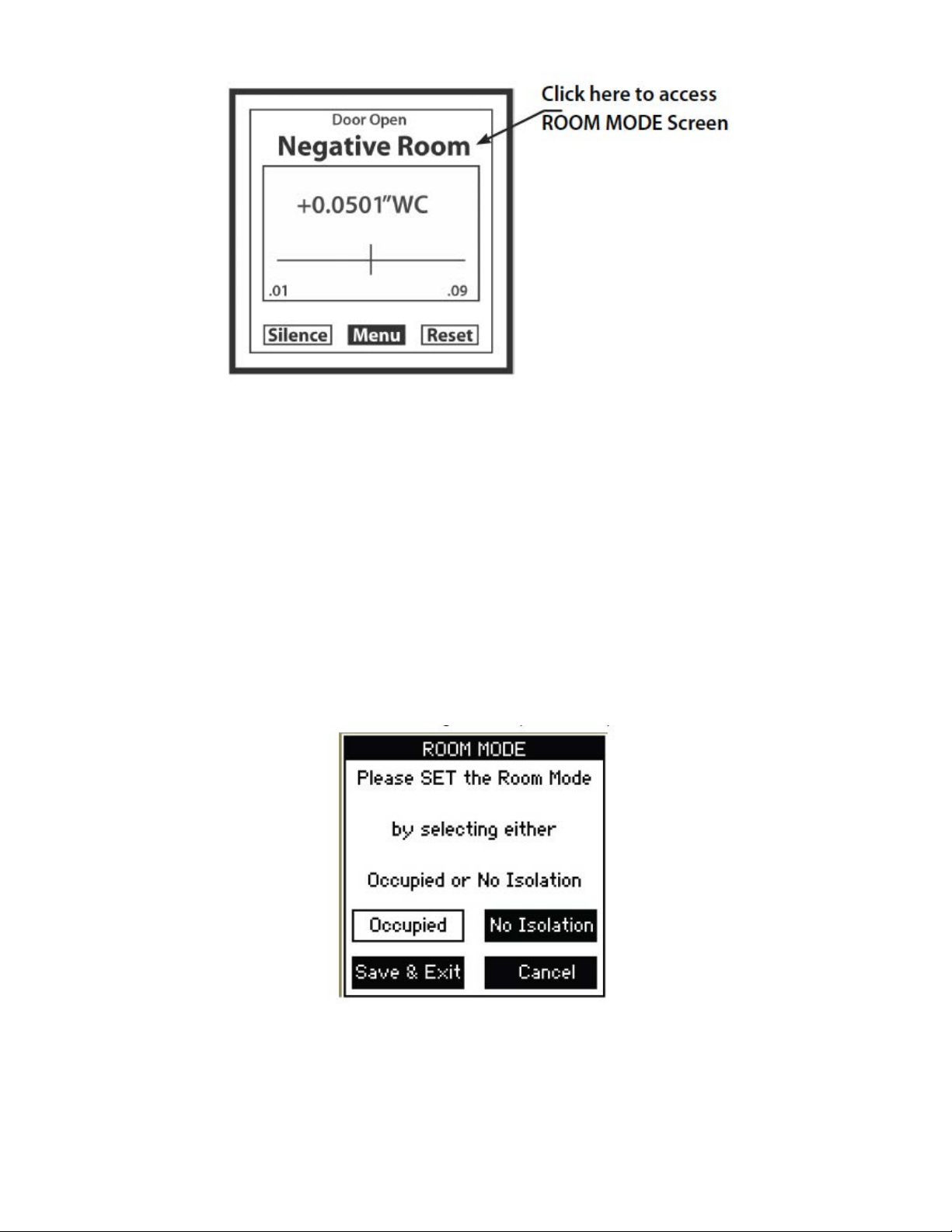
PRESSURE MONITORING SCREENS
At completion of setup, the main display will be the pressure monitoring screen, which
displays the actual room static pressure. The room static pressure is shown as a
number on the LCD as well as a “Moving Bar” indicator operating between the preset
pressure limits. Normal room pressure conditions within the preset pressure limits are
veried by a green colored screen. When the door is opened under conditions within
the preset pressure limits, the screen turns yellow. Room static pressure outside of the
preset pressure limits is indicated by a Red screen after the alarm’s time delay expires.
CHANGING ROOM MODES
The DPG300 can quickly be changed from active monitor alarming to No Isolation (or
unoccupied). To do this, touch the room mode indicator at the top of the pressure monitoring screen (see above.)
OCCUPIED/NO ISOLATION
Use these buttons to quickly change the room to Occupied (Standby) or No Isolation
status. If No Isolation is used there will be no alarms generated if the room is outside
pressure limits.
Press Save and Exit.
23
Page 24
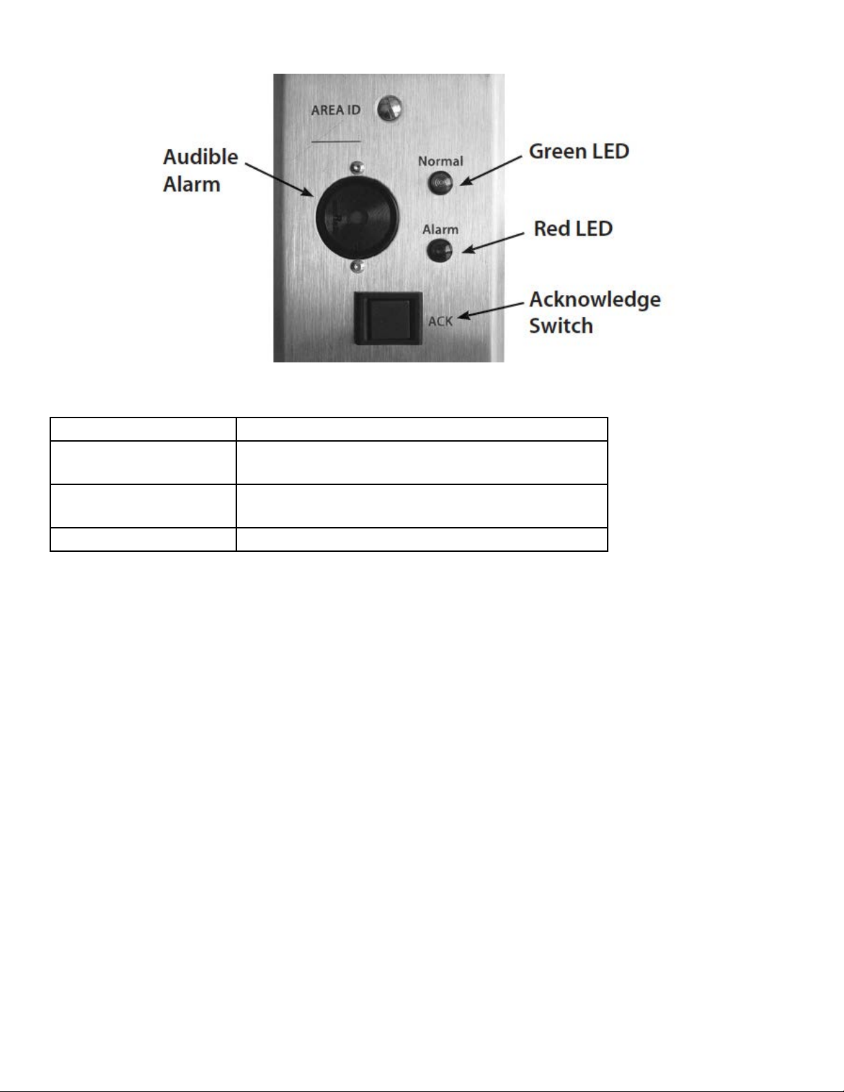
5.0 REMOTE ANNUNCIATOR
The Remote Annunciator provides remote indication of room status.
Green LED Visual indication of normal room condition.
Red LED Visual indication of a breach in room pressure
protection.
Audible Alarm Beeper sounds to indicate breach in room pres-
sure protection.
Acknowledge Switch Press to silence beeper.
OPERATION
Under normal conditions, the green LED remains on. When an alarmed condition
occurs (i.e., room pressure falls outside preset range), a signal is triggered by the
DPG300, the green LED shuts off, the red LED ashes, and the audible alarm sounds.
The acknowledge button can be pressed to momentarily turn-off the audible alarm and
the red LED will continue to ash until the alarmed condition is corrected. When the
alarmed condition is corrected, the annunciator will reset itself. The green LED will turn
on, and the red LED and the audible alarm will shut-off. If the DPG300 reaches the
mute time out limit it will re-sound the alarm.
24
Page 25

6.0 MAINTENANCE
The DPG300 is designed to operate an indoor environment, monitoring clean, dry air.
Upon nal installation of the DPG300 Room Pressure Monitor, no routine maintenance
is required. A periodic check of system calibration is recommended. The DPG300
is not eld serviceable and should be returned if repair is needed (eld repair should
not be attempted and may void warranty). Be sure to indicate a brief description of the
problem plus any relevant application notes Contact customer service to receive a return goods authorization number before shipping.
CLEANING IMPORTANT
Do not blow into the pressure tubing or ttings with mouth, compressed air, or canned
air. Such actions may permanently damage the pressure sensor. Do not clean or
wash-down the DPG300 with industrial cleaners of solvents. The housing may be
wiped down with soap and water or isopropyl alcohol. The LCD may only be cleaned
with isopropyl alcohol. Do not immerse unit.
7.0 AGENCY ELECTRICAL STANDARDS
This device falls into CSA “Pollution Degree 2” for PCB insulation and CSA “Installation
Category 2”.
The DPG300 meets the following requirements:
CSA Standard C22.2 No 0-M 91: General Requirements - Canadian electrical code,
Part 1
CAN/CSA C22.2 No. 0.4-04: Bonding of Electrical Equipment
CAN/CSA-C22.2 No. 61010-1-04: Safety requirements for electrical equipment for
measurement, control and laboratory Use Part-1: General Requirements
ANSI/UL61010-1 (Second Edition): Safety requirements for electrical equipment for
measurement, control and laboratory use Part 1: General Requirements.
25
Page 26
26
Page 27
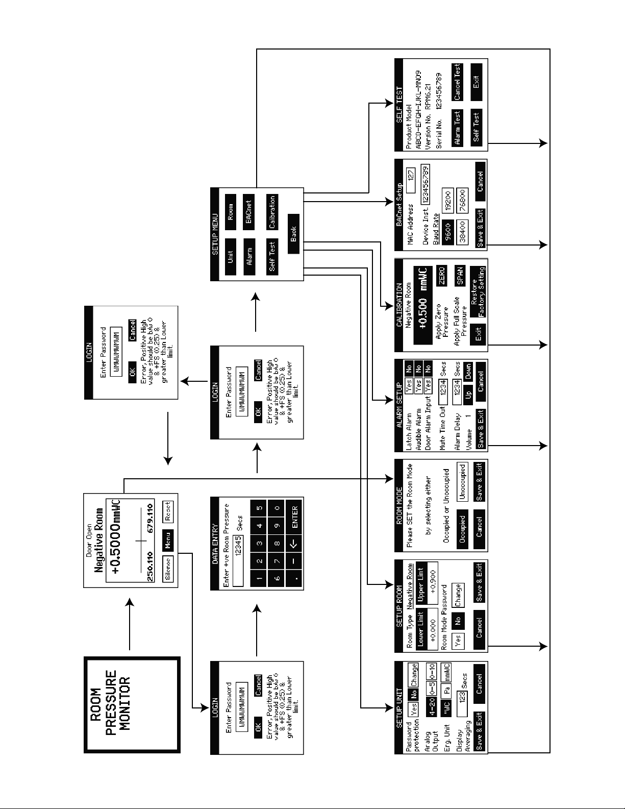
9.0 MENU TREE
Screen
Main Menu
Entered
Correctly
Password
Test Alarm
Self Test Screen
Apply Parameters
Select “Save” to exit.
Setting”
“Restore Factory
Apply Paramters or
entered or
Number of Tries
Wrong password
Pressure
Exceeded the
Maximum Number
of Tries. Return to
Screen
Pressure Monitoring
Screen.
Monitoring
Password Not
Entered Correctly
Data Entry Screen
Enter Parameters
Alarm Setup Screen
Select “Save” to exit.
Setup Room Mode
Select “Save” to exit.
Occupied or No Isolation
Enter Parameters
Setup Room Screen
Select “Save” to exit.
Welcome Screen
Menu Button Pressed
Login Screen
27
Enter Parameters
Setup Unit Screen
Select “Save” to exit.
Page 28

RETURNING PRODUCTS FOR REPAIR
Please contact Omega at 1-800-826-6342 or 1-203-359-1660 before returning unit for repair to review
information relative to your application. Many times, only minor eld adjustments may be necessary.
When returning a product to Omega, the material should be carefully packaged and shipped prepaid
to:
Omega Engineering, Inc
One Omega Drive
P.O. Box 4047
Stamford, CT 06907-0047
To assure prompt handling, please supply the following information and include it inside the package
of returned material:
1. Name and phone number of person to contact.
2. Shipping and billing instruction.
3. Full description of the malfunction.
4. Identify any hazardous material used with product.
Notes: Please remove any pressure ttings and plumbing that you have installed and enclose any required mating electrical connectors and wiring diagrams. Allow approximately 3 weeks after receipt at
Omega for the repair and return of the unit. Non-warranty repairs will not be made without customer
approval and a purchase order to cover the repair charges.
Calibration Services
Omega maintains a complete calibration facility that is traceable to the National Institute of Standards
& Technology (NIST). If you would like to recalibrate or re-certify your Omega pressure transducers or
transmitters, please call our Sales Department at 1-800-826-6342 or 1-203-359-1660 for scheduling,
cost and turnaround estimates.
Thank you,
Omega Engineering, Inc.
28
Page 29

OMEGA ENGINEERING, INC. warrants this unit to be free of defects in materials and workmanship for a period of 13
months from date of purchase. OMEGA’s WARRANTY adds an additional one (1) month grace period to the normal one
(1) year product warranty to cover handling and shipping time. This ensures that OMEGA’s customers receive maximum
coverage on each product.
If the unit malfunctions, it must be returned to the factory for evaluation. OMEGA’s Customer Service
Department will issue an Authorized Return (AR) number immediately upon phone or written request. Upon examination
by OMEGA, if the unit is found to be defective, it will be repaired or replaced at no charge. OMEGA’s WARRANTY does
not apply to defects resulting from any action of the purchaser, including but not limited to mishandling, improper interfac-
ing, operation outside of design limits, improper repair, or unauthorized modication. This WARRANTY is VOID if the unit
shows evidence of having been tampered with or shows evidence of having been damaged as a result of excessive cor-
rosion; or current, heat, moisture or vibration; improper specication; misapplication; misuse or other operating conditions
outside of OMEGA’s control. Components in which wear is not warranted, include but are not limited to contact points,
fuses, and triacs.
OMEGA is pleased to offer suggestions on the use of its various products. However, OMEGA neither assumes
responsibility for any omissions or errors nor assumes liability for any damages that result from the use of its
products in accordance with information provided by OMEGA, either verbal or written. OMEGA warrants only
that the parts manufactured by the company will be as specied and free of defects. OMEGA MAKES NO OTHER
WARRANTIES OR REPRESENTATIONS OF ANY KIND WHATSOEVER, EXPRESSED OR IMPLIED, EXCEPT THAT
OF TITLE, AND ALL IMPLIED WARRANTIES INCLUDING ANY WARRANTY OF MERCHANTABILITY AND FITNESS
FOR A PARTICULAR PURPOSE ARE HEREBY DISCLAIMED. LIMITATION OF LIABILITY: The remedies of purchaser set forth herein are exclusive, and the total liability of OMEGA with respect to this order, whether based on
contract, warranty, negligence, indemnication, strict liability or otherwise, shall not exceed the purchase price of
the component upon which liability is based. In no event shall OMEGA be liable for consequential, incidental or
special damages.
CONDITIONS: Equipment sold by OMEGA is not intended to be used, nor shall it be used: (1) as a “Basic Component”
under 10 CFR 21 (NRC), used in or with any nuclear installation or activity; or (2) in medical applications or used on humans. Should any Product(s) be used in or with any nuclear installation or activity, medical application, used on humans,
or misused in any way, OMEGA assumes no responsibility as set forth in our basic WARRANTY/DISCLAIMER language,
and, additionally, purchaser will indemnify OMEGA and hold OMEGA harmless from any liability or damage whatsoever
arising out of the use of the Product(s) in such a manner.
Direct all warranty and repair requests/inquiries to the OMEGA Customer Service Department. BEFORE RETURNING
ANY PRODUCT(S) TO OMEGA, PURCHASER MUST OBTAIN AN AUTHORIZED RETURN (AR) NUMBER FROM OME-
GA’S CUSTOMER SERVICE DEPARTMENT (IN ORDER TO AVOID PROCESSING DELAYS). The assigned AR number
should then be marked on the outside of the return package and on any correspondence.
The purchaser is responsible for shipping charges, freight, insurance and proper packaging to prevent
breakage in transit.
FOR WARRANTY RETURNS, please have the
following information available BEFORE
contacting OMEGA:
1. Purchase Order number under which the product
was PURCHASED,
2. Model and serial number of the product under
warranty, and
3. Repair instructions and/or specic problems
relative to the product.
OMEGA’s policy is to make running changes, not model changes, whenever an improvement is possible. This affords
our customers the latest in technology and engineering.
OMEGA is a registered trademark of OMEGA ENGINEERING, INC.
© Copyright 2009 OMEGA ENGINEERING, INC. All rights reserved. This document may not be copied, photocopied,
reproduced, translated, or reduced to any electronic medium or machine-readable form, in whole or in part, without the
prior written consent of OMEGA ENGINEERING, INC.
FOR NON-WARRANTY REPAIRS, consult OMEGA
for current repair charges. Have the following
information available BEFORE contacting OMEGA:
1. Purchase Order number to cover the COST
of the repair,
2. Model and serial number of the product, and
3. Repair instructions and/or specic problems
relative to the product.
29
Page 30

TEMPERATURE
Thermocouple, RTD & Thermistor Probes, Connectors, Panels & Assemblies
Wire: Thermocouple, RTD & Thermistor
Calibrators & Ice Point References
Recorders, Controllers & Process Monitors
Infrared Pyrometers
PRESSURE, STAIN AND FORCE
Transducers & Strain Gages
Load Cells & Pressure Gages
Displacement Transducers
Instrumentation & Accessories
FLOW/LEVEL
Rotameters, Gas Mass Flowmeters & Flow Computers
Air Velocity Indicators
Turbine/Paddlewheel Systems
Totalizers & Batch Controllers
pH/CONDUCTIVITY
pH Electrodes, Testers & Accessories
Benchtop/Laboratory Meters
Controllers, Calibrators, Simulators & Pumps
Industrial pH & Conductivity Equipment
DATA ACQUISITION
Data Acquisition & Engineering Software
Communications-Based Acquisition Systems
Plug-in Cards for Apple, IBM & Compatibles
Datalogging Systems
Recorders, Printers & Plotters
HEATERS
Heating Cable
Cartridge & Strip Heaters
Immersion & Band Heaters
Flexible Heaters
Laboratory Heaters
ENVIRONMENTAL
MONITORING AND CONTROL
Metering & Control Instrumentation
Refractometers
Pumps & Tubing
Air, Soil & Water Monitors
Industrial Water & Wastewater Treatment
pH, Conductivity & Dissolved Oxygen Instruments
30
 Loading...