

Page 1
TM
4-20 mA Loop Powered Pressure
Transmitters
DPG1000L, DPG1001L, DPG1100L, DPG1101L
INSTRUCTION
SHEET
M4890/0818
Shop online at omega.com e-mail: [email protected]
For latest product manuals: www.omegamanual.info
DPG1000L 4-20 mA Loop Powered
DPG1001L 4-20 mA Loop Powered, High Accuracy
DPG1000L 4-20 mA Loop Powered, NEMA 4X
DPG1101L 4-20 mA Loop Powered, High Accuracy, NEMA 4X
Ranges and Resolution
Resolution is fixed as indicated below
3-1/2 digit model ranges are limited by number of display digits: 2,
20, 200, and 2000 ranges display 1.999, 19.99, 199.9, and 1999.
psig Gauge reference pressure
psig vacuum Vacuum gauge, minus sign not used
psia Absolute reference (open port reads atmospheric
pressure, reads zero at full vacuum)
Available Ranges
15.00 psig vacuum ‡
30.0 inHg vacuum ‡
±15.0 psig ‡
3.00 psig ‡
5.00 psig ‡
15.00 psia
15.00 psig
30.0 psia †
30.0 psig †
60.0 psig
100.0 psia
100.0 psig
199.9 psig
300 psig †
500 psig
1000 psig (1KG)
1999 psig (2KG)
3000 psi (3KG) *
5000 psi (5KG)
*
Bold Standard ranges. Contact Omega Engineering or other
engineering units such as kPa, atm, bar, mbar, inHg,
mmHg, inH2O, ftH2O, torr, kg/cm2, cmH2O, oz/in2.
‡ DPG1001L , DPG1101L (high accuracy) not available in
3 psi, 5 psi, vacuum, or bipolar ranges.
† DPG1001L , DPG1101L (high accuracy) applies to output
only due to limitation of 3-1/2 digit display.
4 digit range. All others 3-1/2 digit
*
Accuracy
Includes linearity, hysteresis, repeatability
DPG1000L, DPG1100L: ±0.25% of full scale ±1 LSD
DPG1001L, DPG1101L: ±0.1% of full scale ±1 LSD
±0.1% accuracy not available with 3 psig, 5 psig, absolute,
vacuum, or bipolar ranges
Sensor hysteresis: ±0.015% FS, included in accuracy
Sensor repeatability: ±0.01% FS, included in accuracy
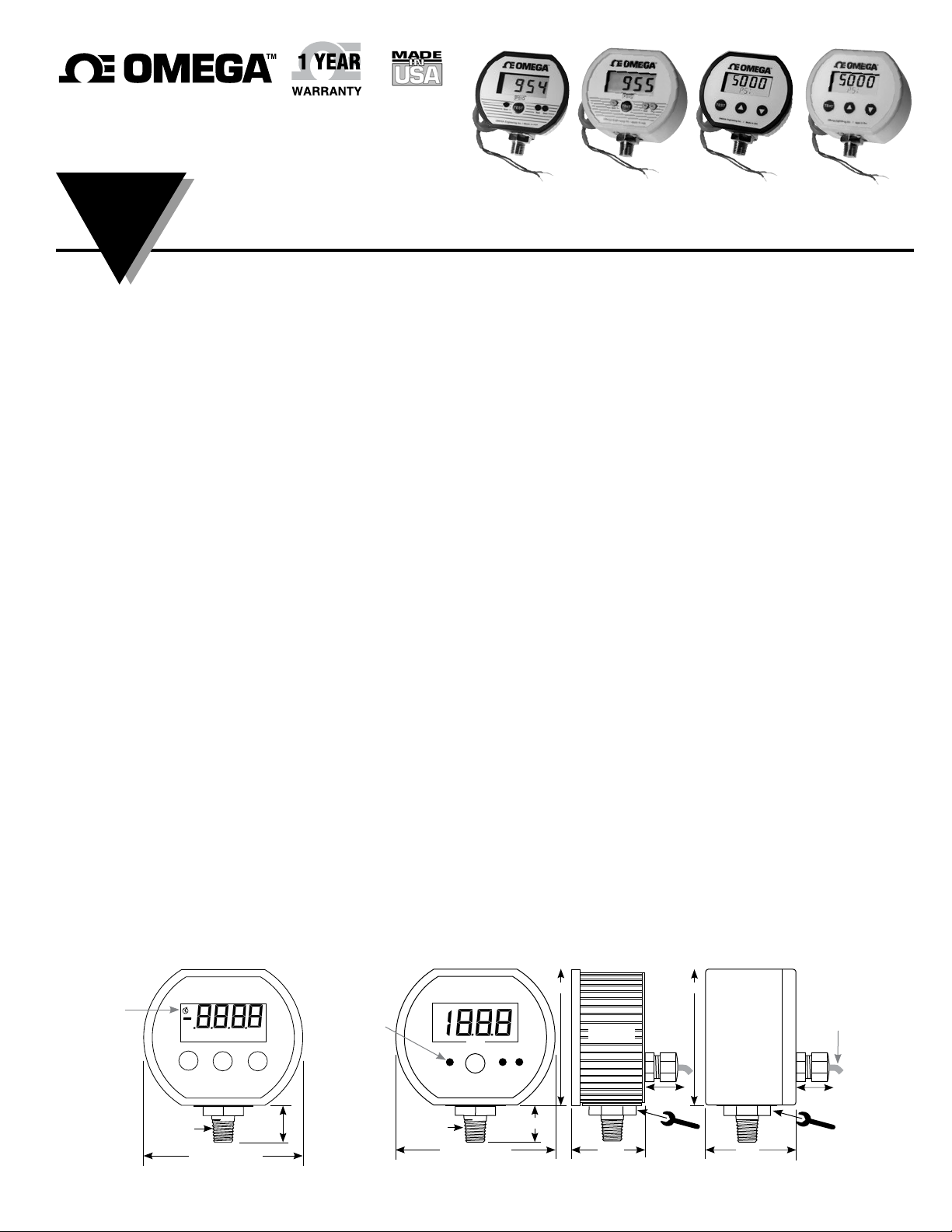
Low voltage
indicator
TEST
OMEGA Engineering Inc. / Made in USA
¼" NPT
3.38" Standard
3.5" NEMA 4X
XXXXX
88888
s t
2
0.75"
Ranges >2000
DPG1000L,
DPG1001L
Display
Resolution is fixed. Some ranges may not use all display digits.
Ranges to 1999: 3-1/2 digit LCD, 1/2" digit height
3 readings/sec. nominal display update
Ranges >2000: 4 digit LCD, 0.4" digit height with 5 character
0.25" H alphanumeric lower display
4 readings/sec. nominal display update
Power
Any DC supply/loop resistance that maintains 8-32 VDC at
gauge terminals.
May be operated as a 4-20 mA loop transmitter or a DC powered pressure indicator.
Reverse polarity protected. Designed for continuous operation.
3 ft long, 2-conductor 22 AWG cable with stripped wire ends
Output Characteristics
Ranges to 1999: Analog output, 50 msec. typical response
time
Ranges 2000-up: 12,000 counts over sensor range
Updated approximately 16 times per second
Low Loop Warning
Ranges to 1999: Colon appears on display at approximately
7.8 VDC. Below 7.8 VDC erratic operation
may occur.
Ranges 2000-up: All decimal points flash. Below 7.8 VDC
erratic operation may occur and gauge may
shut off.
Test Function
TEST button, when depressed sets loop current and display
to output test level, independent of pressure input, to allow
testing of system operation.
Output test adjustment: 0-100% or range
Calibration
Ranges to 1999: Front zero, span and test potentiometers
Non-interactive zero and span, ±10% range
Internal potentiometers: Loop 4 mA and 20 mA
Ranges 2000-up: User set pass code for calibration mode
zero, midpoint, span as required for each range
Process Connection and Material
1/4” NPT male
Sensor and all wetted parts are 316L stainless steel
2.88"
Potentiometer
covers (3)
Standard:
plastic caps
NEMA 4X:
nylon screws
with o-rings
¼" NPT
PSIG
TEST
Span ZeroTest
Cecomp Electronics / Made in USA
3.38" Standard
3.5" NEMA 4X
0.75"
DPG1100L,
DPG1101L
DPG1000L,
DPG1001L,
Ranges >2000
Ranges >2000
The DPG1000L/DPG1100L series is a 2-wire pressure transmitter with a digital display. It is powered by the 4-20 mA current
loop and produces an analog output signal. The output is filtered
to improve noise immunity. It may also be connected to a low
voltage DC supply for use as a pressure indicator.
Ranges up to 1999 have a 3.5 digit display and true analog
output. Ranges 2000 and above are microprocessor based
and use a 4 digit display with an alphanumeric lower display.
The output is a 12,000 count analog 4-20 mA signal updated
approx. 16 times per second.
Models are designed for continuous operation. Warm-up time is
negligible. The display will show the system pressure/vacuum
and the loop current will be proportional to the system pressure/
vacuum; 4 mA = Zero or low end, 20 mA = Span, full-scale or
high end.
The TEST button, when depressed, switches the display and
output loop to a preset level determined by the setting of a Test
potentiometer. This is useful for testing the 4-20 mA output
signal without having to alter system pressure.
Housing
Standard: Epoxy powder coated aluminum case and rear
cover, ABS/polycarbonate bezel, polycarbonate label, front and
rear rubber gaskets
NEMA 4X: UV stabilized ABS/polycarbonate case and
gasketed rear cover with six captive stainless steel screws.
polycarbonate label
Weight
Gauge: 9 ounces, shipping weight: 1 pound (approximate)
Overpressure, Burst, Vacuum
3000 psig sensor: 5000 psig overpressure, 10,000 psi burst
5000 psig sensor: 7500 psig overpressure, 10,000 psi burst
All other sensors: 2 X sensor range overpressure
All other sensors: 4 X sensor range burst
>2X overpressure will permanently damage sensor
Vacuum service: ±15 psig, 15 psia, 15 psig, 30 psia, 100
psig, 100 psia, 200 psig sensors. Vacuum on all others will
permanently damage sensor
4 digit ranges (3000 psi, 5000 psi)
112.5% full scale out-of-range display: 1– – – or 1 –.–.–.–
Under-range display (non-vacuum sensors): –Err
Environmental
Storage Temperature: –40 to 203°F (–40 to 95°C)
Operating Temperature: –4 to 185°F (–20 to 85°C)
Compensated Temperature: 32 to 158°F (0 to 70°C)
3 ft long 2
conductor 22
AWG cable
with stripped
and tinned
wire ends
Allow 1"
clearance
Standard
1.65"
3.0"
Allow 1"
clearance
Turn at hex
fitting only
NEMA 4X
2.0"
DPG1100L,
DPG1101L,
Turn at hex
fitting only
Page 2
2
All Models
Installation Precautions
4 Read these instructions before using the gauge. Configuration
may be easier before installation. Contact the factory for
assistance.
4 These products do not contain user-serviceable parts.
Contact us for repairs, service, or refurbishment.
4 Gauges must be operated within specified ambient
temperature ranges.
4 Outdoor or wash down applications require a NEMA 4X
gauge or installation in a NEMA 4X housing.
4 Use a pressure or vacuum range appropriate for the
application.
4 Use fittings appropriate for the pressure range of the gauge.
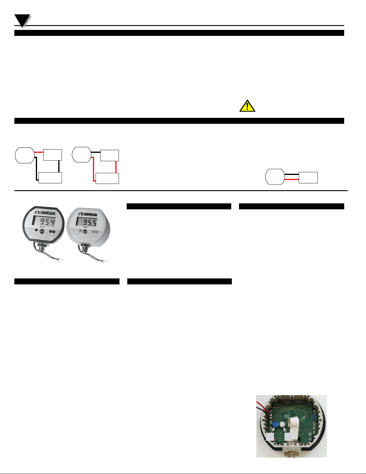
All Models—Electrical Connections
Connect the 2-wire cable to an 8-32 VDC power source. The
gauge will not operate with incorrect polarity. See the wiring
examples below for connecting to a 4-20 mA current loop.
RED +
BLACK –
Power (+)
Power (–)
mA meter (–)
mA meter (+)
BLACK –
- or -
RED +
Power (–)
Power (+)
mA meter (+)
mA meter (–)
4 Due to the hardness of 316 stainless steel, it is recommended
that a thread sealant be used to ensure leak-free operation.
4 For contaminated media use an appropriate screen or filter
to keep debris out of gauge port.
4 Remove system pressures before removing or installing
gauge.
4 Install or remove gauge using a wrench on the hex fitting
only. Do not attempt to turn gauge by forcing the housing.
4 Good design practice dictates that positive displacement
liquid pumps include protection devices to prevent sensor
damage from pressure spikes, acceleration head, and
vacuum extremes.
Select a loop power supply voltage and total loop resistance
so that when the loop current is 20 mA, the gauge will have at
least 8 VDC at its terminals. For correct operation, the gauge
terminal voltage must not fall below 8 VDC. Too large a loop
resistance will cause the gauge output to “limit” or saturate
before reaching its full 20 mA output.
The minimum loop supply voltage may be calculated from the
formula:
Vmin = 8V + (20mA x Total loop resistance)
Avoid permanent sensor damage! Do not apply vacuum to
non-vacuum gauges or hydraulic vacuum to any gauges.
Avoid permanent sensor damage! NEVER insert objects into
gauge port or blow out with compressed air.
Gauges are not for oxygen service. Accidental rupture of
sensor diaphragm may cause silicone oil inside sensor to
react with oxygen.
NEVER connect the gauge wires directly to 115 VAC or
permanent damage will result.
WARNING: This product can expose you to chemicals including
lead, nickel and chromium, which are known to the State of
California to cause cancer or birth defects or other reproductive
harm. For more information go to www.P65Warnings.ca.gov
If the terminal voltage of the gauge falls below about 7.8 VDC,
erratic operation may occur. This is an indication that the
loop supply/resistance may not allow adequate headroom for
reliable operation. This should never occur in normal use. If it
does, examine the loop supply/resistance.
If the 4-20 mA analog output is not required, the transmitter
can be simply connected to any 8-32 VDC power supply.
BLACK –
RED +
Power (–)
Power (+)
DPG1000L, DPG1001L, DPG1100L, DPG1101L Series with Ranges to 1999
Test Function
When the front-panel TEST button is held depressed, the display
and loop current are switched, independent of the system
pressure, to a test level determined by the setting of the Test
potentiometer. This test mode will allow setup and testing of
the current loop by switching to this test level whenever desired
without having to alter the system pressure.
1. To set the test output level, remove the potentiometer cover.
2. Press and hold the front-panel TEST button.
3. Adjust the Test potentiometer to set the display and loop
DPG1000L,
DPG1001L
Operation
Models are designed for continuous operation. Warm-up time
is negligible.
When power is first applied, the gauge will power up and be
ready for use. The display will show the system pressure or
vacuum, and the loop current will be proportional to the system
pressure/vacuum.
Do not apply vacuum unless model range is designated as
vacuum, bipolar, or absolute reference. See specifications for
sensors that can be used for vacuum service. Vacuum will
damage 3 psig, 5 psig, 30 psig, 60, psig, 300 psig, and 500
psig sensors.
Gauge reference pressure ranges
4 mA = Zero or gauge port open to atmosphere
20 mA = Full-scale pressure
Gauge reference vacuum ranges
4 mA = Zero or gauge port open to atmosphere
20 mA = Full-scale vacuum
Bipolar (+/–) ranges
4 mA = Full vacuum
12 mA = Zero or gauge port open to atmosphere
20 mA = Full-scale pressure
Absolute reference ranges
4 mA = Full vacuum (0 on display)
DPG1100L,
DPG1101L
current to the desired test level.
4. Replace the potentiometer cover.
Calibration Preparation
Gauges are calibrated at the factory using equipment traceable
to NIST. There is no need to calibrate the gauge before putting
it into service.
Calibration should only be performed by qualified individuals
using appropriate calibration standards and procedures. Gauges
can be returned to factory for certified calibration and repairs.
NIST traceability is available.
Calibration intervals depend on your quality control program
requirements and as-found data. Many customers calibrate
their equipment annually.
The calibration equipment should be at least four times more
accurate than the gauge being calibrated. The calibration
system must be able to generate and measure pressure and/or
vacuum over the full range of the gauge.
A vacuum pump able to produce a vacuum of 100 microns (0.1
torr or 100 millitorr) or lower is required for vacuum and absolute
gauges.
Warning: application of vacuum to non-vacuum models may
result in irreparable damage to the sensor.
Use a stable DC power supply and an accurate mA meter for
calibration of loop powered transmitters.
Allow the gauge to equalize to normal room temperature (about
20 minutes minimum) before calibration.
20 mA = Full-scale pressure of the sensor used
Note that absolute gauges read atmospheric pressure with the
gauge port open to atmosphere. Atmospheric pressure and
thus the gauge reading, will vary continuously. For example a
15 psia sensor may read 14 psia depending on local barometric
pressure and the effects of altitude.
Calibration
1. See rear label of gauge for pressure range.
2. Remove the covers on the Zero and Span controls on the
front of the gauge.
3. Loop-powered gauges must be connected to 8-32 VDC
during the calibration procedure. The supply voltage has
negligible effects on the gauge calibration as long as it is
within the stated voltage ranges.
4. Internal Zero and Span potentiometers adjust the
agreement between the display and the analog output.
These normally do not need to be adjusted. If the output
does need adjustment, remove the rear cover to access the
potentiometers. See image below.
5. Zero for gauge reference pressure or vacuum gauges:
With the gauge port open to atmosphere, adjust the Zero
potentiometer for a display indication of zero. Output should
be 4.0 milliamps.
Zero for absolute reference gauges: Apply full vacuum to the
gauge. Adjust the Zero potentiometer for a display indication
of zero. Output should be 4.0 milliamps.
6. Span for gauge reference pressure gauges and absolute
reference gauges: Apply full-scale pressure and adjust the
Span potentiometer for a display indication equal to fullscale pressure. Output should be 20.0 milliamps.
Span for gauge reference vacuum gauges: Apply full vacuum
to the gauge. Adjust the Span potentiometer for a display
indication equal to full-scale vacuum. Output should be 20.0
milliamps.
7. Verify pressure indications at 0%, 25%, 50%, 75%, and
100% of full scale and repeat calibration as needed to
achieve best accuracy over desired operating range.
8. Replace the potentiometer covers, rear cover and screws,
taking care not to pinch the wires between the case and the
rear cover.
Loop
Zero
Loop
Span
Page 3
DPG1000L, DPG1001L, DPG1100L, DPG1101L Series with Ranges 2000 and Up
3
DPG1000L,
DPG1001L,
Ranges 2000-up
DPG1100L,
DPG1101L,
Ranges 2000-up
Power Up & Operation
Models are designed for continuous operation. Warm-up time
is negligible.
When power is first applied, the gauge proceeds through a
startup sequence as follows.
1. All active display segments are turned on for approximately
1 second.
2. The full scale pressure is indicated for approximately 1
second, while the engineering units are displayed for 1/2
second on the character segments and then FS (Full Scale)
is displayed for 1/2 second on the character segments.
3. All active display segments are again turned on for
approximately 1 second.
After initialization, the display and the loop current will
correspond to the applied pressure. The output is linearly
proportional to the pressure.
4 mA = Zero or gauge port open to atmosphere
20 mA = Full-scale pressure or vacuum, depending on range
Low Loop Voltage or Out-of-Range Indications
At power-up, if the available voltage is not sufficient, only
the low power segment will be displayed indicating that loop
resistance is too high or the loop power supply voltage is too
low.
After successful power-up, if the loop voltage falls below
the minimum required for reliable operation, the display will
continue to indicate pressure with the low power segment
blinking at a slow rate.
Pressure out-of-range indication
112.5% out-of-range display: 1 – – – or 1 –.–.–.– depending
on model.
Test Function
When the front-panel TEST button is held depressed, the display
and loop current are switched, independent of the system
pressure, to a test level determined by the test setting.
This test mode will allow setup and testing of the current loop
by switching to this test level whenever desired without having
to alter the system pressure.
1. To set the test output level, press and hold the front-panel
TEST button.
2. Press the s or t buttons to adjust the test output to the
desired pressure setting.
3. Release the TEST button. The setting is stored in non-volatile
memory.
When the TEST button is held depressed, the display and loop
current are switched, independent of the actual pressure,
to a level determined by the test setting. When the button is
released, normal operation is resumed.
Calibration Preparation
Gauges are calibrated at the factory using equipment traceable
to NIST. There is no need to calibrate the gauge before putting
it into service.
Calibration intervals depend on your quality control program
requirements and as-found data. Many customers calibrate
their equipment annually.
Calibration should only be performed by qualified individuals
using appropriate calibration standards and procedures. Gauges
may be returned to Omega for NIST traceabile calibration.
The calibration equipment should be at least four times more
accurate than the gauge being calibrated. The calibration
system must be able to generate and measure pressure/
vacuum over the full range of the gauge.
A vacuum pump able to produce a vacuum of 100 microns
(0.1 torr or 100 millitorr) or lower is required for vacuum and
absolute gauges. Warning: application of vacuum to nonvacuum models will result in damage to the sensor.
Connect to a stable 8-32 VDC power supply during the
calibration procedure. The supply voltage has negligible effects
on the gauge calibration as long as it is within the stated voltage
ranges. Over voltage may result in damage.
Use an accurate mA meter for calibration of the 4-20 mA output.
Allow approximately 20 minutes for the gauge to equalize to
normal room temperature before calibration.
Entering Calibration Mode
1. While pressing and holding the t button, press the TEST
button to enter the calibration mode. The upper section of
the display will indicate CAL.
2. When all buttons are released, the upper section of the
display will indicate _ _ _ _ with the left-most position
blinking, and the lower section will indicate PASS. To exit
and return to the normal operating mode, press and release
the TEST button.
3. Enter the user-modifiable calibration pass code (3510
factory default).
Use the s and t buttons to set the left-most digit to 3.
Press and release the TEST button to index to the next
position. The 3 will remain, and the second position will be
blinking. Use the s and t buttons to select 5.
Press and release the TEST button to index to the next
position. 3 5 will remain, and the third position will be
blinking. Use the s and t buttons to select 1.
Press and release the TEST button to index to the next
position. 3 5 1 will remain, and the fourth position will be
blinking. Use the s and t buttons to select 0.
4. Press and release the TEST button to proceed with
calibration.
If an incorrect pass code was entered, the gauge will to exit to
the normal operating mode.
Upon successful calibration pass code entry, the upper display
will indicate the applied pressure with the corresponding loop
current through the gauge wires.
The lower display will alternate between CAL and the calibration
region corresponding to the applied pressure (ZERO, +MID,
+SPAN, –MID, or –SPAN).
Note: To store the calibration parameters and exit calibration
mode at any time, press and hold the TEST button until the
display indicates – – – – .
Loop Current Calibration
Loop current calibration coordinates the loop current to the
display indication, and is performed independently of applied
pressure. It requires a direct physical measurement of the loop
current. See the wiring instructions.
Note: During any of the following calibration steps if the TEST
button is held depressed for longer than 2 seconds, the display
will change to indicate – – – – , and the gauge will exit the
calibration mode when all buttons are released.
4 mA loop current calibration
Press the TEST button and release it when the display indicates
LCAL.
The upper display segments will indicate the pre-configured
pressure corresponding to a 4 mA loop current.
The lower display will alternate between CAL and 4 MA.
Use the s and t buttons to adjust the actual loop current
to 4 mA.
20 mA loop current calibration
Press the TEST button and release it when the display indicates
HCAL.
The upper display segments will indicate the pre-configured
pressure corresponding to a 20 mA loop current.
The lower display will alternate between CAL and 20 MA.
Use the s and t buttons to adjust the actual loop current to
20 mA.
Pressure Calibration
The pressure calibration procedure simultaneously adjusts both
the display indication and the loop current to correspond to the
actual applied pressure.
Note: During any of the following calibration steps if the TEST
button is held depressed for longer than 2 seconds, the display
will change to indicate – – – – , and the gauge will exit the
calibration mode when all buttons are released.
Zero calibration
Press the TEST button and release it when the display indicates
CAL.
Apply zero pressure.
The lower display will alternate between CAL and ZERO.
Use the s and t buttons to adjust the upper display to indicate
zero.
Span calibration
Apply full-scale pressure.
The lower display will alternate between CAL and +SPAN.
Use the s and t buttons to adjust the upper display to indicate
the applied pressure.
Midpoint non-linearity calibration
Apply 50% full-scale positive pressure.
The lower display will alternate between CAL and +MID.
Use the s and t buttons to adjust the upper display to indicate
the applied pressure.
Save and exit
To store the calibration parameters and exit calibration mode,
press and hold the TEST button until the display indicates – – – – .
Change Calibration Pass Code
1. While pressing and holding the s button, press the TEST
button to enter the configuration mode. The upper section of
the display will indicate CFG.
2. When all buttons are released, the upper section of the
display will indicate _ _ _ _ with the left-most position
blinking, and the lower section will indicate PASS. To exit
and return to the normal operating mode, press and release
the TEST button.
3. Enter factory pass code 1220
Use the s and t buttons to set the left-most digit to 1.
Press and release the TEST button to index to the next
position. The 1 will remain, and the second position will be
blinking. Use the s and t buttons to select 2.
Press and release the TEST button to index to the next
position. 1 2 will remain, and the third position will be
blinking. Use the s and t buttons to select 2.
Press and release the TEST button to index to the next
position. 1 2 2 will remain, and the fourth position will be
blinking. Use the s and t buttons to select 0.
4. Press and release the TEST button to proceed to the
configuration parameters. Note: If an incorrect pass code was
entered, the gauge will exit to the normal operating mode.
5. The upper display section will indicate the calibration pass
code. The lower section will display UDPCD.
6. To change the calibration pass code, press and release
either the s or t buttons. The first character of the pass
code will begin to blink.
Use the s and t buttons to set the blinking character to the
desired value, then press and release the TEST button to move
to the next character. Repeat for each character position.
7. When the calibration pass code is displayed with no
characters blinking, press and release the TEST button to
save the new pass code and restart the gauge.
Note: To make a correction to the new calibration pass
code before saving and restarting, press either the s or t
buttons to return to the UDPCD code entry sequence.
Page 4

WARRANTY/DISCLAIMER
OMEGA ENGINEERING, INC. warrants this unit to be free of defects in materials and workmanship for a period
of 13 months from date of purchase. OMEGA’s WARRANTY adds an additional one (1) month grace period
to the normal one (1) year product warranty to cover handling and shipping time. This ensures that
OMEGA’s customers receive maximum coverage on each product.
If the unit malfunctions, it must be returned to the factory for evaluation. OMEGA’s Customer Service
Department will issue an Authorized Return (AR) number immediately upon phone or written request.
Upon examination by OMEGA, if the unit is found to be defective, it will be repaired or replaced at no
charge. OMEGA’s WARRANTY does not apply to defects resulting from any action of the purchaser,
including but not limited to mishandling, improper interfacing, operation outside of design limits,
improper repair, or unauthorized modification. This WARRANTY is VOID if the unit shows evidence of
having been tampered with or shows evidence of having been damaged as a result of excessive corrosion;
or current, heat, moisture or vibration; improper specification; misapplication; misuse or other operating
conditions outside of OMEGA’s control. Components in which wear is not warranted, include but are not
limited to contact points, fuses, and triacs.
OMEGA is pleased to offer suggestions on the use of its various products. However,
OMEGA neither assumes responsibility for any omissions or errors nor assumes liability for
any damages that result from the use of its products in accordance with information provided
by OMEGA, either verbal or written. OMEGA warrants only that the parts manufactured by the
company will be as specified and free of defects. OMEGA MAKES NO OTHER WARRANTIES OR
REPRESENTATIONS OF ANY KIND WHATSOEVER, EXPRESSED OR IMPLIED, EXCEPT THAT OF
TITLE, AND ALL IMPLIED WARRANTIES INCLUDING ANY WARRANTY OF MERCHANTABILITY
AND FITNESS FOR A PARTICULAR PURPOSE ARE HEREBY DISCLAIMED. LIMITATION OF
LIABILITY: The remedies of purchaser set forth herein are exclusive, and the total liability of
OMEGA with respect to this order, whether based on contract, warranty, negligence,
indemnification, strict liability or otherwise, shall not exceed the purchase price of the
component upon which liability is based. In no event shall OMEGA be liable for
consequential, incidental or special damages.
CONDITIONS: Equipment sold by OMEGA is not intended to be used, nor shall it be used: (1) as a “Basic
Component” under 10 CFR 21 (NRC), used in or with any nuclear installation or activity; or (2) in medical
applications or used on humans. Should any Product(s) be used in or with any nuclear installation or activity,
medical application, used on humans, or misused in any way, OMEGA assumes no responsibility as set forth
in our basic WARRANTY/DISCLAIMER language, and, additionally, purchaser will indemnify OMEGA and hold
OMEGA harmless from any liability or damage whatsoever arising out of the use of the Product(s) in such a
manner.
RETURN REQUESTS/INQUIRIES
Direct all warranty and repair requests/inquiries to the OMEGA Customer Service Department. BEFORE
RETURNING ANY PRODUCT(S) TO OMEGA, PURCHASER MUST OBTAIN AN AUTHORIZED RETURN (AR)
NUMBER FROM OMEGA’S CUSTOMER SERVICE DEPARTMENT (IN ORDER TO AVOID PROCESSING
DELAYS). The assigned AR number should then be marked on the outside of the return package and on any
correspondence.
The purchaser is responsible for shipping charges, freight, insurance and proper packaging to prevent
breakage in transit.
FOR WARRANTY RETURNS, please have the
following information available BEFORE contacting
OMEGA:
1. Purchase Order number under which the product
was PURCHASED,
2. Model and serial number of the product under
warranty, and
3. Repair instructions and/or specific problems
relative to the product.
OMEGA’s policy is to make running changes, not model changes, whenever an improvement is possible. This affords
our customers the latest in technology and engineering.
OMEGA is a registered trademark of OMEGA ENGINEERING, INC.
© Copyright 2017 OMEGA ENGINEERING, INC. All rights reserved. This document may not be copied, photocopied,
reproduced, translated, or reduced to any electronic medium or machine-readable form, in whole or in part, without the
prior written consent of OMEGA ENGINEERING, INC.
FOR NON-WARRANTY REPAIRS,
for current repair charges. Have the following
information available BEFORE contacting OMEGA:
1. Purchase Order number to cover the COST
of the repair,
2. Model and serial number of the product, and
3. Repair instructions and/or specific problems
relative to the product.
consult OMEGA
 Loading...