

Page 1
RoHS 2 Compliant
User’s Guide
Shop online at
omega.com
e-mail: [email protected]
For latest product manuals:
www.omegamanual.info
SM
DPF6000/DPF5000
Programmable Counter/Timer
Page 2

omega.com [email protected]
Servicing North America:
U.S.A. Omega Engineering, Inc.
Headquarters: Toll-Free: 1-800-826-6342 (USA & Canada only)
Customer Service: 1-800-622-2378 (USA & Canada only)
Engineering Service: 1-800-872-9436 (USA & Canada only)
Tel: (203) 359-1660 Fax: (203) 359-7700
e-mail: [email protected]
For Other Locations Visit omega.com/worldwide
The information contained in this document is believed to be correct, but OMEGA accepts no liability for any errors it contains, and reserves
the right to alter specifications without notice.
Page 3

i
PART ONE QUICK-START GUIDE
TABLE OF CONTENTS PAGE
1.0 GENERAL INFORMATION ................................................................................................1-1
2.0 GETTING STARTED ..........................................................................................................1-2
2.1 Safety Considerations ..............................................................................................1-2
2.2 Assembly & Mounting “Classic” ..............................................................................1-3
2.3 Assembly & Mounting “Designer” ............................................................................1-6
3.0 POWER AND SIGNAL CONNECTIONS ..........................................................................1-10
3.1 Turning It On ..........................................................................................................1-10
3.2 Testing....................................................................................................................1-10
4.0 EASY PROGRAMMING WITH DISPLAY PROMPTS ....................................................1-11
4.1 Features ................................................................................................................1-11
4.2 Display Symbols and Descriptions ........................................................................1-14
4.3 Programming Pushbuttons ....................................................................................1-15
4.4 Factory-Default Settings ........................................................................................1-16
4.5 Programming and Application Examples ..............................................................1-16
APPENDICES
APPENDIX A MODIFICATIONS - JUMPER DIAGRAMS................................................1-25
A.1 Lockout Features............................................................................................1-25
A.2 Frequency Response ....................................................................................1-26
APPENDIX B CONTROL INPUTS/OUTPUTS ................................................................1-27
Free software for OMEGA devices featuring Ethernet or Serial Communications
is on the CD-ROM enclosed with this shipment.
To download the latest software release (or request a free CD-ROM) please go to:
www.omega.com/software
Page 4

ii
ILLUSTRATIONS PAGE
Figure 2-1 Exploded View “Classic” ........................................................................................1-3
Figure 2-2 Case Dimensions, Front View “Classic” ................................................................1-5
Figure 2-3 Exploded View “Designer” ....................................................................................1-6
Figure 2-4 Case Dimensions, Front View “Designer”..............................................................1-8
Figure 2-5 Rear Views ............................................................................................................1-9
Figure 3-1 Rear Panel Pin Assignments ..............................................................................1-10
Figure A-1 Display Board Jumper Locations ........................................................................1-25
Figure A-2 Main Board Jumper Locations ............................................................................1-26
Table B-1 Output Effect Immediately After RESET ..............................................................1-27
Page 5

iii
PART TWO REFERENCE
TABLE OF CONTENTS PAGE
5.0 PROGRAMMING ................................................................................................................2-1
5.1 General Information ................................................................................................2-1
5.2 Selecting the Function to be Performed ..................................................................2-2
5.3 Multiply or Divide by a Scale Factor ........................................................................2-2
5.4 Selecting an Offset ..................................................................................................2-3
5.5 Choosing Auto-Range or Fixed Display Decimal-Point Location ............................2-3
5.6 Selecting Rising or Falling Edge Triggers for A and B Inputs..................................2-3
5.7 Setting Lower and Upper Alarm (or Control) Values................................................2-5
5.8 Selecting a Gate Time..............................................................................................2-6
5.9 Configuration #1 and #2 ..........................................................................................2-6
5.10 Calibration of the Crystal Frequency ......................................................................2-6
5.11 Replacing the Stored Program with the Active Program ........................................2-7
6.0 REMOTE PROGRAMMING................................................................................................2-7
6.1 General Information ................................................................................................2-7
6.2 ASCII Output ............................................................................................................2-8
6.3 Setup Data ..............................................................................................................2-9
6.4 ASCII Input ............................................................................................................2-12
6.5 Interfacing Examples..............................................................................................2-13
6.6 Programming Considerations ................................................................................2-14
6.7 Parity Checking ......................................................................................................2-18
6.8 Timing ....................................................................................................................2-18
6.9 Modem Operation ..................................................................................................2-18
6.10 0 - 20 mA, ASCII Output ........................................................................................2-18
7.0 TROUBLESHOOTING CHART ........................................................................................2-20
Page 6

iv
PAGE
8.0 SPECIFICATIONS ............................................................................................................2-22
8.1 General Information ..............................................................................................2-22
8.2 Input Characteristics ..............................................................................................2-22
8.3 Display ..................................................................................................................2-23
8.4 Output Characteristics............................................................................................2-23
8.5 Time Base ..............................................................................................................2-23
8.6 Communication ......................................................................................................2-24
8.7 Frequency/Period Function ....................................................................................2-24
8.8 Time Interval ..................................................................................................2-25
8.9 Frequency Ratio,
B
..............................................................................................2-25
8.10 Totalize ..................................................................................................................2-26
8.11 Power ....................................................................................................................2-26
9.0 DRAWINGS ......................................................................................................................2-27
APPENDICES
APPENDIX C THEORY OF OPERATION ......................................................................2-35
APPENDIX D GLOSSARY OF SYMBOLS AND TERMS................................................2-41
APPENDIX E APPLICATION NOTES ............................................................................2-44
APPENDIX F POWER OUTPUT/INPUT ........................................................................2-55
INDEX..........................................................................................................................................2-57
A
Page 7

v
ILLUSTRATIONS PAGE
Figure 6-1 Connection of Serial Port to IBM Computer
with D-25 Connector ..............................................................................................2-13
Figure 6-2 Ribbon Cable and Mass Termination to Connect Serial Port
to IBM Computer with D-9 Connector....................................................................2-14
Figure 6-3 Modem Concept ....................................................................................................2-18
Figure 6-4 Programming Commands ......................................................................................2-19
Figure C-1 Resolution Comparison of Meter to Conventional Counters ................................2-35
Figure C-2 Burst Frequency Measurement..............................................................................2-36
Figure C-3 Time-Interval Measurement Timing........................................................................2-37
Figure C-4 Frequency Ratio Measurement Timing..................................................................2-38
Figure C-5 Timing in Totalize Function ....................................................................................2-39
Figure E-1 Time-Interval Measurement ..................................................................................2-44
Figure F-1 Side View of Transformer ......................................................................................2-55
Figure F-2 Connection of an External Battery ........................................................................2-56
TABLES PAGE
Table 5-1 Lock-Out Jumpers....................................................................................................2-1
Table E-1 Time with No Input to Read Zero ..........................................................................2-54
Page 8

vi
Page 9
1.0 GENERAL INFORMATION
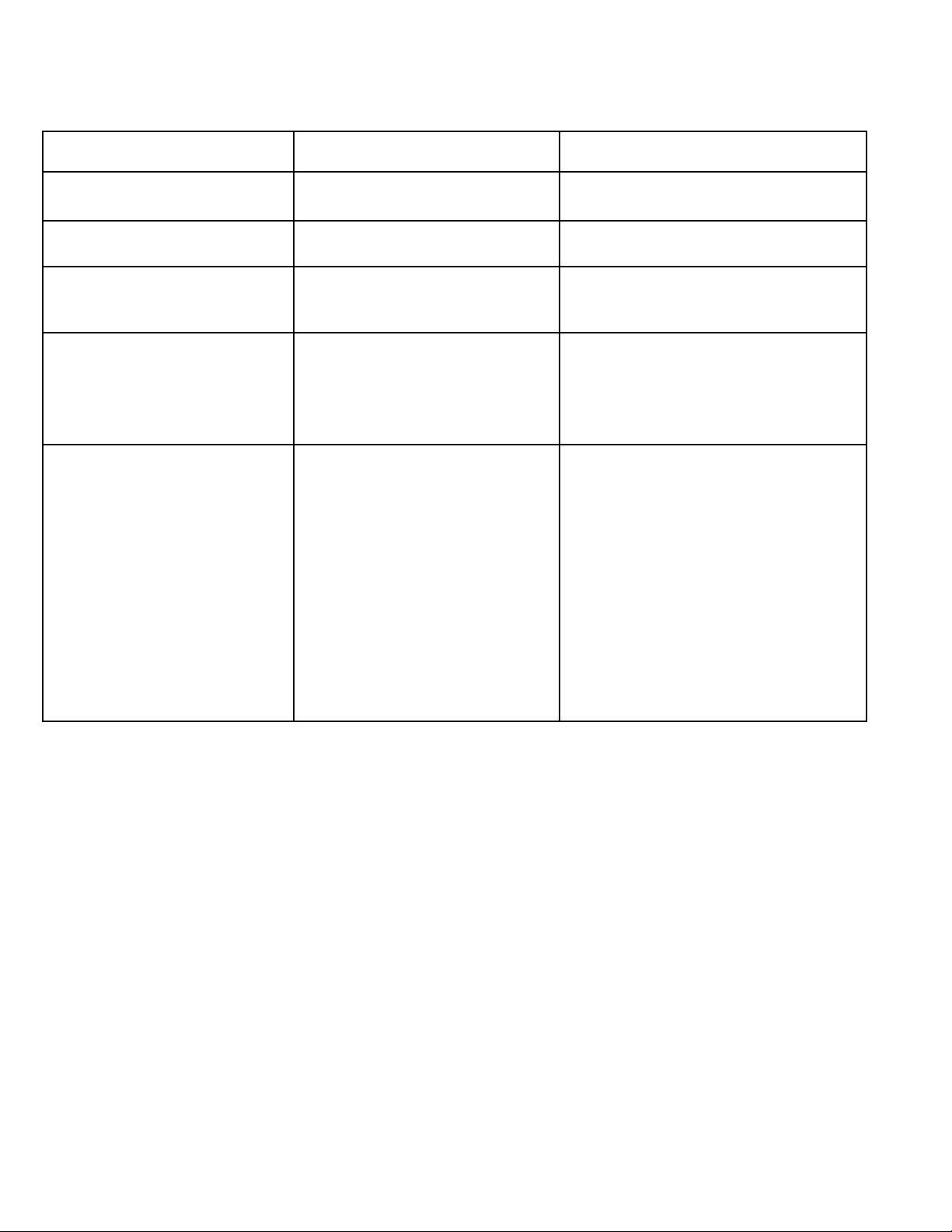
Listed below are the differences between the different meter styles.
P6000 P6000A/DPF6000 P5000/DPF5000
“Classic”front panel. “Classic” front panel. New “Designer” front panel.
NEMA-4 w/ cover. NEMA-4 w/ cover. NEMA-4 standard.
Meter slides out of case Meter slides out of case Meter slides out of case
from front. from front. from rear.
Front panel to display Front panel to display Front panel to display
board mounting: board mounting: board mounting:
not compatible to not compatible to P6000. not compatible to P6000.
P6000A & P5000.
Front panel is removable Front panel is removable Front panel is not removable.
to adjust potentiometers to adjust potentiometers Potentiometers and
on input options boards* on input options boards* programming pins may
and programming pins. and programming pins. be adjusted by removing
Input & output option or meter from case*.
boards may not be A slot at top of case is or
compatible to P6000A & provided for possilbe A slot at top of case is
P5000. location of potentiometers provided for possible location
access. Input Option of potentiometers access.
boards may not be Input option boards may not be
Reference for P6000 Manual - 10980ML-01 compatible to P6000. compatible.
* Detailed information in the input options manual.
1-1
Page 10

1-2
This meter is a fully programmable counter with six-digit resolution for totalizing
input pulses or for measuring frequency, period, time interval and frequency ratio.
The meter is menu-driven for simple programming. Alphanumeric prompts on the
display make it easy to program with front panel pushbuttons. Pushing the appropriate|
button scrolls the display through the functions and settings, repeating (for corrections) as
often as desired. Alternatively, a personal computer can be used to program the meter
and to monitor the display data via the RS-232 port (standard feature). If desired, the
program setup may be stored in nonvolatile memory for recall upon demand or at
power-on.
The two setpoints and corresponding alarm outputs make it an ON-OFF Controller for
either stand-alone or computer-controlled applications. The crystal time base may be
electronically calibrated, either manually from the front panel or remotely with a personal
computer.
2.0 GETTING STARTED
2.1 SAFETY CONSIDERATIONS
This instrument is protected according to Class II of IEC 348 and VDE 0411. To ensure
safe operation, follow the guidelines below:
POWER VOLTAGE - Verify that the instrument is connected for the power voltage rating that will
be used.
POWER WIRING - This instrument has no power-on switch; it will be in operation as soon as
the power is connected.
RAIN OR MOISTURE - Do not expose the instrument to condensing moisture.
FUMES AND GASES - Do not operate the instrument in the presence of flammable gases or
fumes.
EXERCISE CAUTION - As with any electronic instrument, high voltages may be exposed when
attempting to install, calibrate, or remove parts of the meter.
Page 11
1-3
2.2 ASSEMBLY & MOUNTING
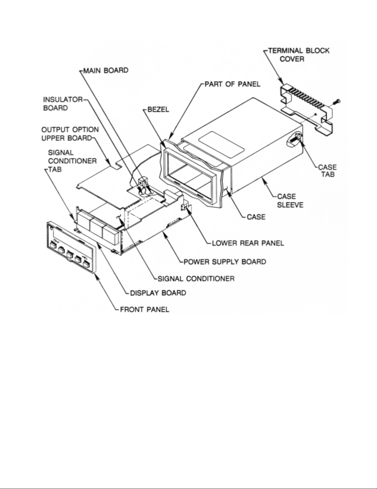
Figure 2-1 Exploded View - “Classic” Style
Page 12

1-4
The “Classic” meter is housed in a 4896-150, 1/8 DIN case. The electronic circuitry can be
installed or removed from the front and is attached to the case with two #8 screws through
the rear panel.
To install a pre-configured meter:
NOTE: Installation of input options (mezzanine board) and output options (upper board)
is shown in the Input Options and the Output Options Manuals.
1. Use a Phillips-head screwdriver to remove the three screws on the rear of the case
2. Slide the sleeve off the case (see Figure 2-1 Exploded View).
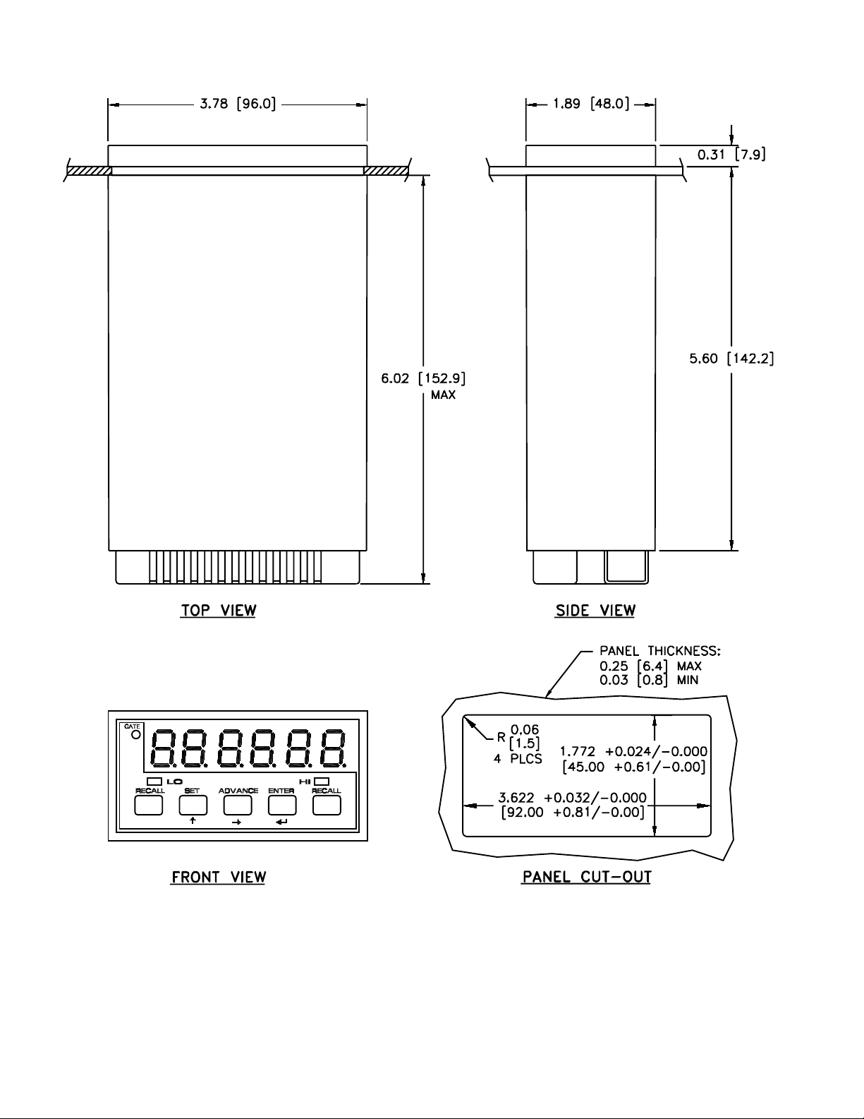
3. Verify the panel cutout dimensions in Figure 2-2 Case Dimensions. Insert the case in the
pane cutout from the front and slide the sleeve on from the rear. Install the two #8 screws
to secure the sleeve to the case.
4. Connect all connectors and attach the terminal block cover with the #4 screw.
Page 13
1-5
Figure 2-2 Case Dimension, Front View - “Classic Style”
Page 14
1-6
2.3 ASSEMBLY AND MOUNTING
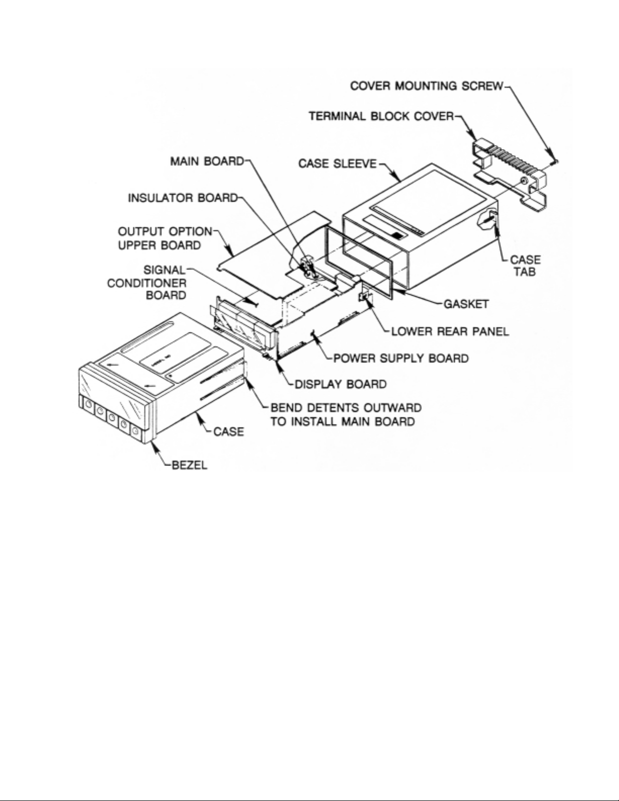
Figure 2-3 Exploded View - “Designer” Style
Page 15
1-7
The “Designer” meter circuit boards are housed in a 4896 1/8-DIN plastic case and sleeve.
The bezel, display lens and pushbuttons are NEMA-4 (waterproof) sealed to the case; the
electronics assembly slides into the case from the rear when the flexible side panel detents
are moved aside. Six front pins on the electronics assembly then mate with the connectors
on the inside of the case.
To install a preconfigured meter:
NOTE: The main board, display board and power supply board are soldered together
as a basic unit. Installation of input options (mezzazine board) and output options
(upper board) is shown in the Input Options and the Output Options Manuals.
1. Use a phillips-head screwdriver to remove the three screws on the rear of the case.
2. Slide the case sleeve off the case.
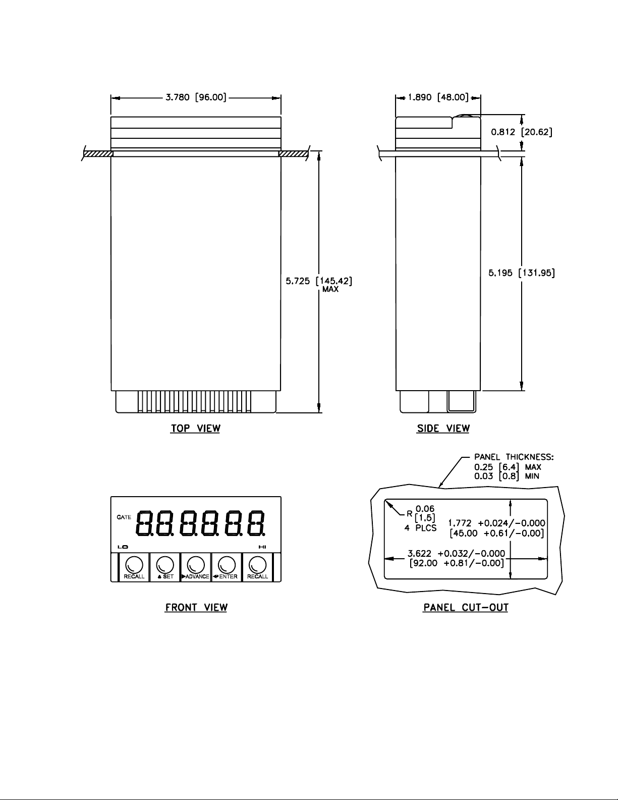
3. Verify the panel cutout dimensions in Figure 2-4 Case Dimensions. For panel mounting,
the entire edge of the panel cutout is sandwiched between the bezel (and gasket) in front
and the sleeve in the rear. Install the two #8 screws to secure the sleeve to the case.
4. Connect all connectors and attach the terminal block cover with the #4 screw.
Page 16
1-8
Figure 2-4 Case Dimensions, Front View - “Designer” Style
Page 17
1-9
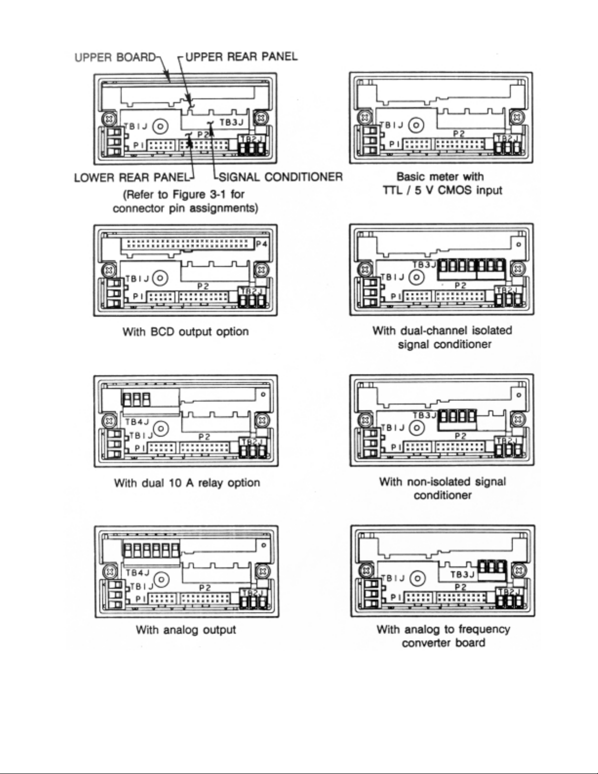
Figure 2-5 Rear Panel Views
Page 18
1-10
3.0 POWER AND SIGNAL CONNECTIONS
3.1 TURNING IT ON
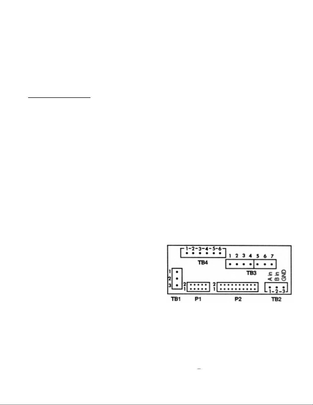
INCORRECT POWER INPUT CAN DAMAGE YOUR P6000A/P5000 COUNTER
Connect the proper voltage to the power screw terminal (TB1). The meter will display the
programmed function (default is FrEq) until it reads the input signal. Then that value will
be shown.
CONNECT
OR DETAIL
P2 P1
1 SPARE FF D IN 1 N/C
2 SPARE FF RESET IN 2 N/C
3 SPARE FF Q OUT 3 RS-232 DATA OUT
4 SPARE FF Q OUT 4 RS-232 RTS IN
5 SPARE FF CLK IN 5 RS-232 DATA IN
6 GROUND 6 N/C
7 ALARM HI OUT 7 N/C
8 +5 V OUT 8 N/C
9 ALARM LO OUT 9 RS-232 GND
10 ALARM GO OUT 10 0-20mA ASCII OUT
11 V+ IN/OUT
12 GROUND
13 HOLD IN N/C = No Internal Connection
14 BUFFER IN
15 BUFFER OUT
16 BLANK ENABLE IN*
17 GROUND
18 RESET IN
19 EXT. GATE IN
20 DIGIT 6 OUT (400 Hz)
3.2 TESTING
To verify the default settings, connect a TTL-compatible signal source between pins 1
(SIG HI) and 3 (SIG GND) on the TB2 connector. For test purposes, the 400 Hz digit-drive
output (connector P2-pin 20) can be connected to the signal input, TB2-pin 1. If digit
output is connected to signal input, display reads 400.0
+
.1% Hz.
Figure 3-1 Rear Panel Pin Assignments
*or LINE FREQ OUT
(USA=120 Hz, EURO=100 Hz
With dual 10 A relays and dual-channel
isolated pulse signal conditioner
9.5 - 32 V 115 OR 230 V
DC POWERED AC POWERED
NC AC HI
+ AC LO
- AC GND
Page 19

1-11
4.0 EASY PROGRAMMING WITH DISPLAY PROMPTS
Section 4 explains the front-panel programmable features (in bold), their display character,
and how to modify the existing setup.
4.1 FEATURES
Frequency Measures the input frequency. Displays in Hz (Scale Factor = 1); can also
display in kHz, RPM (for tachometer application), feet/sec, or other engineering
units.
Period Measures the input period (inverse of frequency) and displays in milliseconds
can also display in seconds, minutes, or other engineering units.
Time Interval Use for pulse width measurement, or for stopwatch applications where reset
after each measurement is desired. Measures the time interval (or average
time interval) between the rising or falling edges of two signals. Displays in
milliseconds (Scale Factor = 1); can also display in seconds, minutes, or other
engineering units.
Frequency Used as an FB/FA frequency ratio meter with FB and FA up to 7 MHz. Ideal for
Ratio b/A monitoring the relative speed of shafts, conveyor belts and other moving
machinery.
Totalize Use for cumulative totals, stopwatch applications, as an up-counting (positive
scale factor) or down-counting (negative scale factor) totalizer.
Scale factor The input may be multiplied or divided by any desired scale factor from -
9.9.9.9.9. to +9.9.9.9.9.9. with a decimal point selected in any position shown.
Offset After measuring the input(s), the meter multiplies or divides the result by
the scale factor and then adds the offset. The offset value can range from -
99999
to 999999 *. Like SCALE, the decimal point is programmable.
Range The decimal point can be selected on any of the six positions F.F.F.F.F.F. or it
can (Display be floating (Auto-range). It should be noted that when a fixed
decimal point is Decimal selected, the meter maintains a meaningful unit of
measurement in the Point) reading. For example, if input frequency is 10 Hz,
function
equals frequency, and fixed decimal point equals 3, the display reads
10.00, not .10.
* The offset is limited to +390000 in units manufactured prior to January 1988 if the scale facto
is positive.
Page 20
1-12
Slope Determines which edge of the input pulse begins the measurement.
Frequency, Period and Totalize measure A Input; Time Interval and
Frequency Ratio measure both A and B Inputs.
Setpoints -.9.9.9.9.9 to 9.9.9.9.9.9.
After applying the scale factor and offset, the displayed measurement is
compared to the setpoint values.
A high or low alarm LED lights when the display falls outside of a setpoint.
Three open-collector transistors with active-low alarm outputs correspond to
the LO, GO and HI alarms.
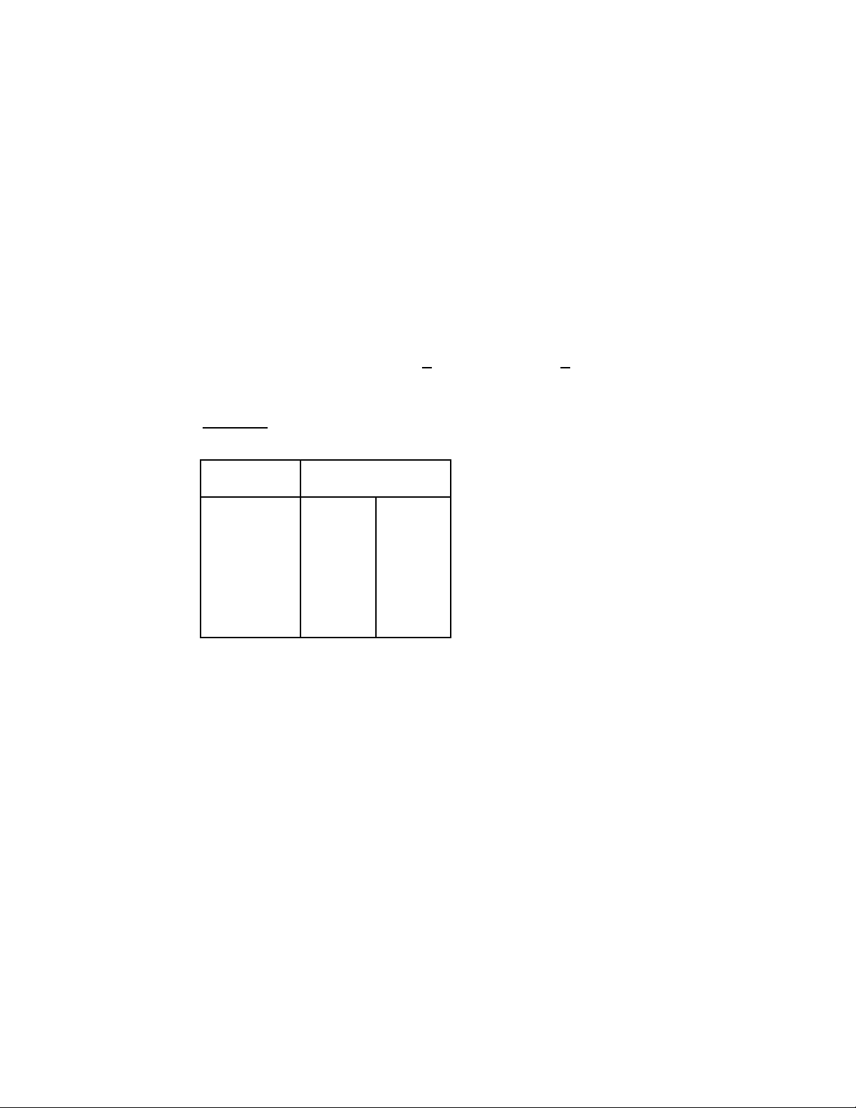
LO ALARM: Displayed value < SETPOINT LO
HI ALARM: Displayed value > SETPOINT HI
GO ALARM: SETPOINT LO <
Displayed value < SETPOINT HI
Example
: Setpoint HI is 500.0 and Setpoint LO is -100.0
LED Alarm Lights
Reading LO HI
500.1 Off On
500.0 Off Off
10.5 Off Off
-99.8 Off Off
-100.2 On Off
To convert Setpoint LO to a second high setpoint, set software switch 5 of
Configuration 2 to a '1' (CnFG 2 = X1XXXX). LO ALARM becomes active when
the reading is greater (more positive) than that setpoint. The GO alarm still
becomes active when neither the LO nor the HI alarm is active.
Gate time Partially controls the reading rate; the Gate LED lights during gate time.
Page 21
1-13
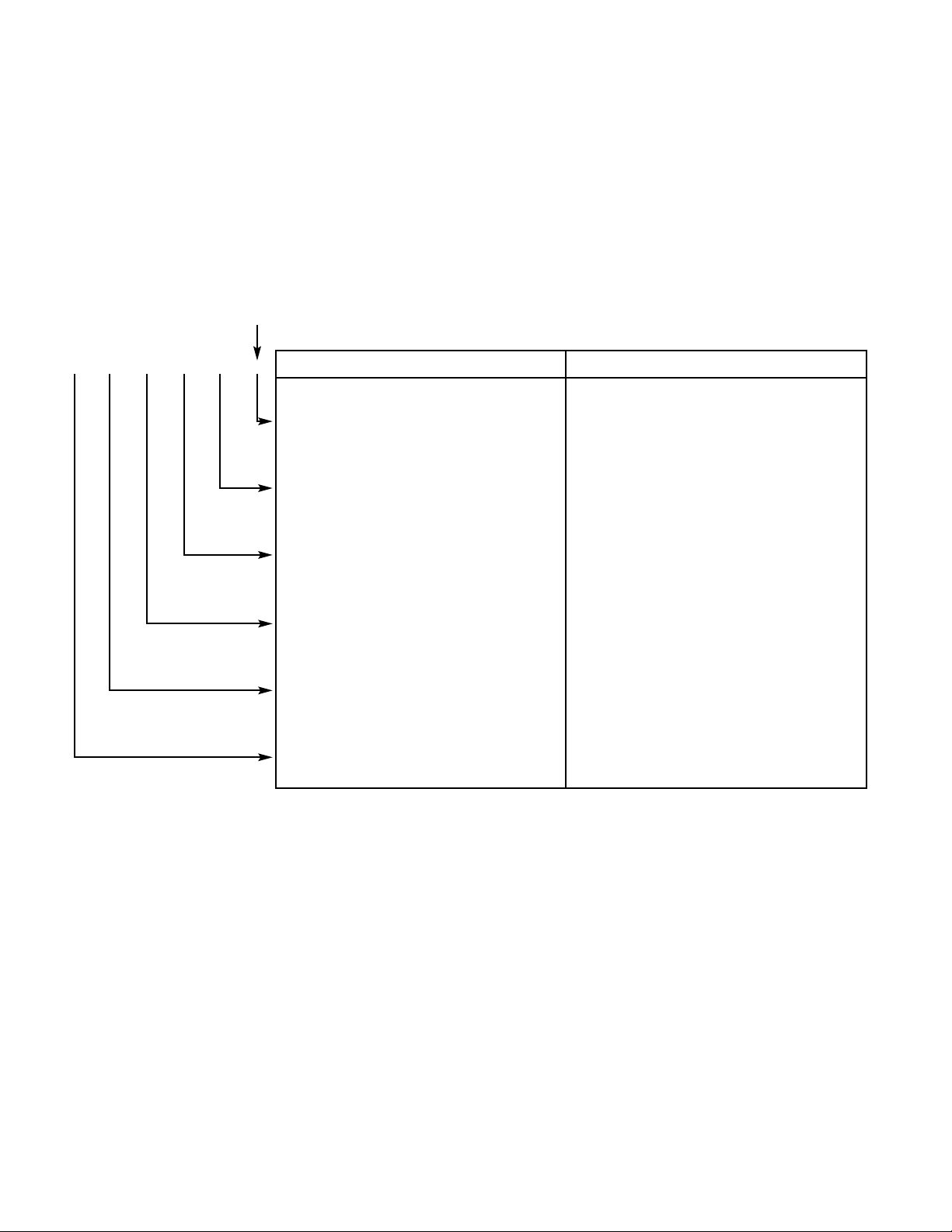
Configurations These program internal software switches (SS# below) which specify display
1 and 2 brightness, baud rate, zero blanking; activate external or interna gate inputs;
modify alarm conditions.
Each display digit carries a software switch function in Configurations 1 and 2.
The functions are modified using the front-panel pushbuttons.
8.8.8.8.8.8.
SS6 SS5 SS4 SS3 SS2 SS1 CONFIGURATION 1 CONFIGURATION 2
1=Display leading zeros 1=Display 50% brightness
0=Blank leading zeros 0=Full brightness (if SS2 = 0)
1=1200 BAUD rate 1=Display 25% brightness
0=9600 BAUD rate 0=Full brightness (if SS1 = 0)
1=RTS handshake per character
1=Transmit data to parallel BCD
0=RTS handshake per message 0=Do not transmit data
1=Zero with No Input 1=Latch alarm outputs
0=Allow Low Frequency 0=Do not latch
1=Ext. gate input active low 1=Change low alarm to high alarm
0=Ext. gate input active high 0=Normal low alarm action
1=Disable internal gate time 1=No units-of-measure displayed
0=Enable internal gate time 0=Display units-of-measure
Calibration Factory standard locks out this feature. Recalibration requires simple jumper
configuration and front panel pushbutton programming.
Store (save) The meter is microcomputer based and allows two memory modes:active and
nonvolatile. Active memory consists of your latest programmed data. Once the
data (and settings) is "stored", it becomes saved in nonvolatile memory and can
be restored upon power up. At power loss or "recall", any data in active memory
is lost (unless previously stored).
Page 22

1-14
4.2 DISPLAY SYMBOLS AND DESCRIPTIONS
AA ..SSCC
Scale Factor is a MULTIPLIER. Display = (measurement .scale) + offset
AA//SSCC
Scale Factor is a DIVIDER. Display = (measurement / scale) + offset
AA nnEEGG
A input trigger slope is NEGATIVE (counting negative edges)
AA PPOOSS
A input trigger slope is POSITIVE (counting positive edges)
AAuuTToo
Auto-ranging is selected. The meter selects the decimal point.
bb nnEEGG
B input trigger slope is NEGATIVE (counting negative edges)
bb PPOOSS
B input trigger slope is POSITIVE (counting positive edges)
CCAALLIIbb
CALIBRATION value, expressed in parts per million
-99999 to 999999 ppm with six possible decimal point positions
CCnnFFGG 11
CONFIGURATION 1, set of six software switches, SS1 - SS6. Six digits on the
display, each can be set to 0 or 1 to disable or enable a feature.
CCnnFFGG 22
CONFIGURATION 2, set of six software switches, SS1 - SS6. Six digits on the
display, each can be set to 0 or 1 to disable or enable a feature.
FF..FFFFFFFFFF
FIXED RANGE, with selected decimal point flashing.
FFrr bb//AA
Operating mode is Frequency Ratio B/A (B input is divided by the A input)
FFrrEE99
Operating mode is Frequency (measures the A input frequency)
FFuunncc
Function. Used to select the operating mode.
GGAAttEE tt
Nominal GATE TIME, the averaging time that determines the display update rate.
The value ranges from 00.00 to 99.99 seconds, with a fixed decimal point.
OOFFFFSSEEtt
OFFSET (Preset). Display = (Input x Scale) + Offset
Ranges from -99999 to 999999 with a programmable decimal point.
PPEErriioodd
Operating mode is Period.
rrAAnnGGEE
Range can be set to autorange (with a floating decimal point) or have a fixed
decimal point location.
SSCCAALLEE
Scale factor. Ranges from -99999 to 999999 with a programmable decimal point.
Multiply or divide.
SSLLOOPPEE
Trigger SLOPE of the Input(s). Positive or negative slopes can be selected for A
and B inputs, independently.
SSPP HHII
High setpoint. Ranges from -99999 to 999999 with a programmable decimal point.
SSPP LLOO
Low setpoint. Ranges from -99999 to 999999 with a programmable decimal point.
ttii IInntt
Operating mode is Time Interval, A to B.
ttoottAALL
Operating mode is Totalize.
Page 23
1-15
4.3 PROGRAMMING PUSHBUTTONS
Your meter was programmed per the factory-default settings shown in Section 4.4 unless you
ordered it factory-programmed for your requirements. To change this setup, programming from
the front panel is made simple by use of pushbuttons.
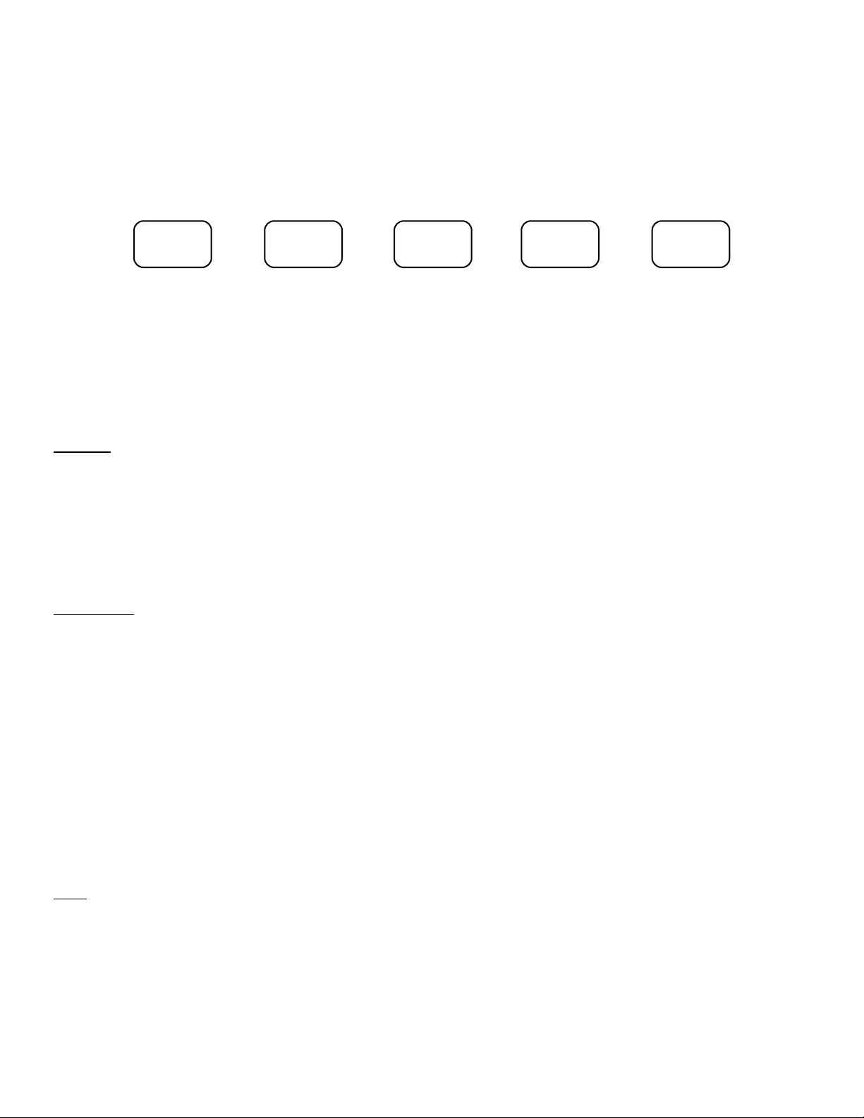
RECALL SET ADVANCE ENTER RECALL
Push in this order: ENTER - scrolls through the main menu selection
ADVANCE - scrolls through the sub-menu selection and the
digital position on the display
SET - modifies functions or settings
ENTER - enters the modification into active memory
ENTER
After entering a change, the meter automatically displays the next menu
title. The main menu titles appear in this order: Func, SCALE, OFFSEt,
rAnGE, SLOPE, SP LO, SP HI, GAtE t (not in Totalize), CnFG 1, CnFG 2,
CALIb (may be locked out), noStor. One or more of the main menu titles may
be skipped, if locked out (bypassed) by jumper installation on pin groups S7
and S8.
ADV
ANCE After a menu title has been selected (using ENTER), push ADVANCE to take
the program into the sub-menu for that item. For instance, push ADVANCE
after SP HI is displayed to show the setpoint number. Push ADVANCE
repeatedly to change a flashing location, which indicates the position or function
that will change (a digit or decimal point in this example). The actual
modification is made with the SET button, and the modification is entered into
memory using ENTER . The display then shows the next main menu item
(GAtE t in this example).
Push ADVANCE after Func is displayed to show the current active function:
FrEq, PEriod, Ti Int, Fr b/A or totAl. This function will show up flashing,
indicating that it can be modified with the SET button.
SET
Once a selection is made, push SET to modify the function or number which is
flashing. Push ENTER to enter the modification into the active memory.
(This is not stored.)
Page 24

1-16
RECALL
Pushed simultaneously, the two RECALL buttons reset the meter. The last
program stored (saved) is read into active memory and will be displayed. As in
a power loss, data not stored is lost.
Push SET ADVANCE ENTER simultaneously to reset the counter and start a
measurement using the latest settings (in active memory).
4.4 FACTORY-DEFAULT SETTINGS
Programmable Features
Operating Mode (Function) Frequency
Setpoints Hi = 100000. Lo = 0.00000
Scale Multiply by 1.00000
Offset 000000.
Range Fixed decimal point, FFFFFF.
Trigger slope A and B Positive
Nominal gate time 0.3 second (00.30)
Configuration 1 000000
Configuration 2 000001
Calibration as appropriate
(lock-out jumper installed)
Jumpers Installed
Display board: S7-B, S8-A Locks out calibration feature
Main board: SA-M, SB-M DC-100 kHz frequency response;
-20 to +25 volts maximum input
4.5 PROGRAMMING AND APPLICATION EXAMPLES
The pushbuttons scroll through the menu items repeatedly, making corrections or changes
simple. If a setting is correct, just press ENTER.
Page 25
1-17
FREQUENCY MEASUREMENT
A sensor generates one pulse for every revolution of a shaft. To measure the input frequency
and display in RPM (instead of Hz), set SCALE FACTOR to 60.
Features used: Function - set to Frequency mode
Scale - use "multiply by" and 60.0000
Range - autorange or fixed decimal point location,
depends on application
Store - optional, stores in nonvolatile memory
Flashing indicates the position or function that will change.
PUSH
DISPLAY SHOWS NOTES
ENTER
FFuuNNcc
SET
FFrrEE99
Press until flashing FrEq is displayed.
ENTER
SSCCAALLEE
SET
AA..SSCC
or
AA//SSCC
A.SC (multiply by), A/SC (divide by)
A.SC <--- SET ---> A/SC
ADVANCE
11..0000000000
--->
11..0000000000
Scrolls the position you can set. Applies to
digits and decimal point.
SET
11..0000000000
--->
66..0000000000
ADVANCE to the digit or decimal-point
66..0000000000
--->
6600..00000000
position you wish to change, then press
SET until the desired value or decimalpoint location is reached.
ENTER
OOFFFFSSEEtt
ADVANCE
000000000000
Verify it is set to 000000. If the offset is
other than 000000, change as previously
done in Scaling, using SET and ADVANCE.
ENTER
rrAAnnGGEE
Can be set to Auto-range (floating decimal
point) or to use a fixed decimal point.
ADVANCE
FFFFFFFFFFFF
. Auto <--- ADVANCE ---> F.FFFFF
To change the decimal-point location,
press SET to scroll to the desired location.
`
`
`
`
`
`
`
`
`
`
`
`
`
`
`
`
`
`
`
`
`
`
`
`
`
`
`
`
`
`
`
`
`
`
Page 26
1-18
ENTER
SSLLOOPPEE
Sub-menus are A pos or A neg.
A POS <--- SET ---> A nEG
Either one may be used with frequency applications.
ENTER
SSPP LLOO
Using ADVANCE and SET, you may enter a low
setpoint.
ENTER
SSPP HHII
Using ADVANCE and SET, you may enter a high
setpoint.
ENTER
GGaattEE tt
Select from 00.00 to 99.99 seconds using ADVANCE
and SET.
ENTER
CCnnFFGG 11
Controls software switches for leading zeros, baud
rate, etc. Refer to Configuration charts in Section 4.1
FEATURES for selection. Use ADVANCE and SET
buttons to change.
ENTER
CCnnFFGG 22
Controls software switches for display brightness,
alarm outputs, etc. Refer to Configuration charts in
Section 4.1 FEATURES for selection.
ENTER
nnooSSttoorr
CAUTION: The settings are in active (VOLATILE)
memory for use until power is disconnected or new
settings are entered. DO NOT PRESS ENTER IF
YOU WISH TO SAVE THE NEW SETUP.
SET
SSttoorrEE
Once the data is "Stored" in nonvolatile memory,
these settings will restore at power-on or when both
RECALL buttons are pushed simultaneously.
ENTER
BEGIN MEASUREMENT - To reset the counter and start a measurement, simultaneously press
SET ADVANCE ENTER . NOTE: If a signal is connected to the input, a frequency reading in
RPM replaces this display.
Scale Factor Formula: If more than one pulse per revolution, use this formula to determine
scale factor.
SCALE = Multiply by
60
Example: 10 pulses per revolution => SCALE = X 6
n
`
`
`
`
`
`
`
`
Page 27
1-19
LINE FREQUENCY MEASUREMENT
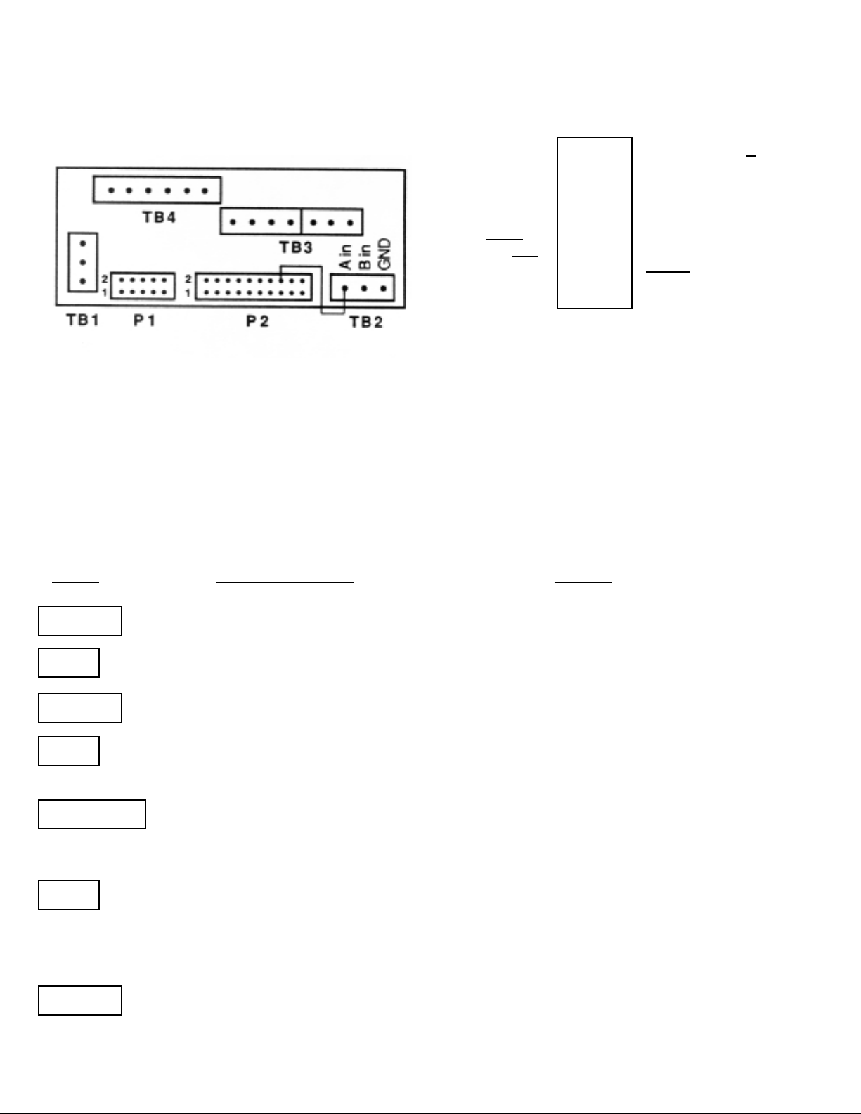
To monitor line frequency with 4-digit resolution, such as 60.00, connect the line frequency output
to the A input. (Connect P2-pin 16 to TB2-pin 1.)
Features used: Function -set to Frequency mode
Scale - use "divide by" and 2
Offset - set to 000000
Range - use FFFF.FF decimal-point setting
Store - optional, stores in nonvolatile memory
Flashing indicates the position or function that will change.
PUSH
DISPLA
Y SHOWS NOTES
ENTER
FFuuNNcc
SET
FFrrEE99
Press SET until flashing FrEq is displayed.
ENTER
SSCCAALLEE
SET
AA..SSCC
or
AA//SSCC
A.SC (multiply by), A/SC (divide by)
A.SC <--- SET ---> A/SC
ADVANCE
11..0000000000
---->
11..0000000000
Scrolls the position you can set.
Applies to digits and decimal point.
SET ADVANCE to the digit you wish to change, then
press SET until the desired value or decimal-point
location is reached.
ENTER
OOFFFFSSEEtt
`
`
`
`
P2
SPARE FF D IN 1 2 SPARE FF RESET IN
SPARE FF Q OUT 3 4 SPARE FF Q OUT
SPARE FF CLK IN 5 6 GND
ALARM HI OUT 7 8 +5 V OUT
ALARM LO OUT 9 10 ALARM GO OUT
V+ IN/OUT 11 12 GND
HOLD IN 13 14 BUF IN
BUF OUT 15 16 BLANK ENABLE IN *
GND 17 18 RESET IN
EXT. GATE IN 19 20 DIGIT 6 TEST OUT
* or LINE FREQUENCY OUT
(USA = 120 Hz, EUROPE = 100 Hz)
`
`
`
`
`
`
`
`
`
`
`
`
Page 28
1-20
ADVANCE
000000000000
If the offset is other than 000000, change as
previously done in Scaling, using SET and ADVANCE.
ENTER
rrAAnnGGEE
Can be set to Auto-range (floating decimal point) or
to use a fixed decimal point.
ADVANCE
FFFFFFFFFFFF..
Press ADVANCE to change Auto-range to fixed
decimal point, then press SET to scroll the decimal
point to FFFF.FF
.
ENTER
SSLLOOPPEE
Sub-menus are A pos or A neg.
A POS <--- SET ---> A nEG
Either one may be used with frequency applications.
ENTER
SSPP LLOO
Using ADVANCE and SET, you may enter a low
setpoint.
ENTER
SSPP HHII
Using ADVANCE and SET, you may enter a high
setpoint.
ENTER
GGaattEE tt
Select from 00.00 to 99.99 seconds using
ADVANCE and SET as in Scaling.
ENTER
CCnnFFGG 11
Controls software switches for leading zeros,
baud rate, etc. Refer to Configuration charts in
Section 4.1 FEATURES for selection. Use
ADVANCE and SET buttons to change.
ENTER
CCnnFFGG 22
Controls software switches for display brightness,
alarm outputs, etc. Refer to Configuration charts
in Section 4.1 FEATURES for selection.
ENTER
nnooSSttoorr
CAUTION: The settings are in active (VOLATILE)
memory for use until power is disconnected or new
settings are entered. DO NOT PRESS ENTER IF
YOU WISH TO SAVE THE NEW SETUP.
SET
SSttoorrEE
Once the data is "Stored" in nonvolatile memory,
these settings will restore at power-on or when
both RECALL buttons are pushed simultaneously.
ENTER
BEGIN MEASUREMENT - To reset the counter and start a measurement, simultaneously press
SET ADVANCE ENTER . NOTE: If a signal is connected to the input, a frequency reading
in RPM replaces this display.
`
`
`
`
`
`
`
`
`
`
`
`
Page 29
1-21
TOTALIZE
To use the meter as a totalizer permanently, the function should be set to totAL and his
change should be stored in nonvolatile memory to restore at power-on. For down counting,
use a negative scale factor and a positive offset. In case of power failure, the meter blanks
the display and stores the latest reading in nonvolatile memory
.
Example: Use Totalize to count parts per container.
Six parts per one container would be as follows.
Features used: Function - set to Totalize mode
Scale - use "divide by" and scale factor of "6"
Store - optional, saves setup in nonvolatile memory
Flashing indicates the position or function that will change.
PUSH
DISPLAY SHOWS NOTES
ENTER
FFuunncc
SET
ttoottAALL
Press until flashing totAL is displayed.
ENTER
SSCCAALLEE
SET
AA..SSCC
or
AA//SSCC
A.SC (multiply by), A/SC (divide by)
A.SC <--- SET ---> A/SC
ADVANCE
11..0000000000
--->
11..0000000000
Scrolls the position you can set. Applies to digits
and decimal-point location.
SET
ADVANCE to the digit you wish to change, the
left-most position for this example, then press SET
until the desired value (6) or decimal- point location
is reached.
ENTER
OOFFFFSSEEtt
Use SET and ADVANCE features to set the
offset. Set it to any value that you want to start
counting; 000000. in this case.
ENTER
rrAAnnGGEE
ADVANCE
FFFFFFFFFFFF..
Auto <--- ADVANCE ---> F.FFFFF
SET scrolls through the decimal- point locations.
`
`
`
`
`
`
`
`
`
`
`
`
`
`
`
`
`
`
`
`
Page 30
1-22
SET
FFFFFFFFFFFF
. Push SET until decimal point is at the desired fixed
location.
ENTER
SSLLOOPPEE
Sub-menus are A pos or A neg.
A POS <--- SET ---> A nEG
Either one may be used with frequency applications.
ENTER
SSPP LLOO
Using ADVANCE and SET, you may enter a low
setpoint.
ENTER
SSPP HHII
Using ADVANCE and SET, you may enter a high
setpoint.
ENTER
CCnnFFGG 11
Controls software switches for leading zeros,
baud rate, etc. Refer to Configuration charts in
Section 4.1 FEATURES for selection. Use
ADVANCE and SET buttons to change.
ENTER
CCnnFFGG 22
Controls software switches for display brightness,
alarm outputs, etc. Refer to Configuration charts
in Section 4.1 FEATURES for selection.
ENTER
nnooSSttoorr
CAUTION: The settings are in active (VOLATILE)
memory for use until power is disconnected or new
settings are entered. DO NOT PRESS ENTER IF
YOU WISH TO SAVE THE NEW SETUP.
SET
SSttoorrEE
Once the data is "Stored" in nonvolatile memory,
these settings will restore at power-on or when
both RECALL buttons are pushed simultaneously.
ENTER
BEGIN MEASUREMENT - To reset the counter and start a measurement, simultaneously press
SET ADVANCE ENTER .
`
`
`
`
Page 31
1-23
STOPWATCH IN TOTALIZE
Stopwatch applications can be used in Totalize or Time-Interval mode. For cumulative time,
use Totalize. (If the result should be reset after each measurement, use Time Interval.)
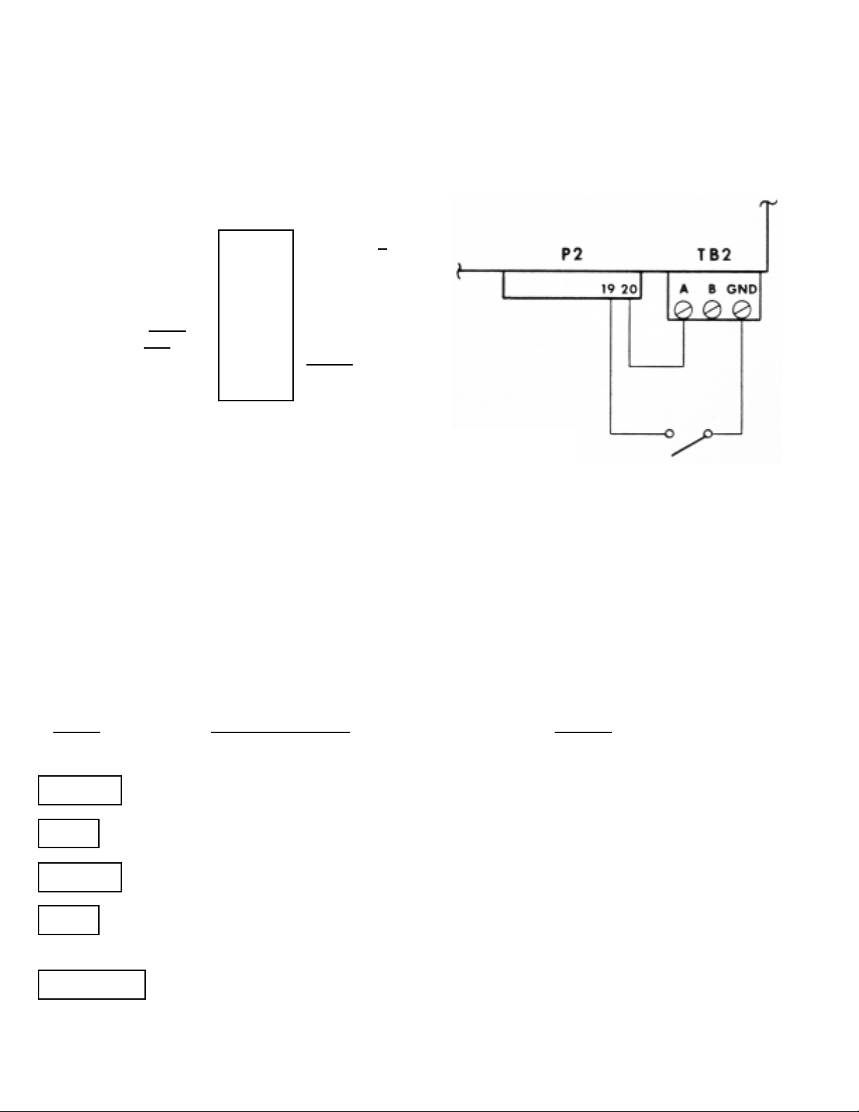
Connect as shown below. This shows use of the 400 Hz output at P2-pin 20 and the
external gate pin 19.
P2
SPARE FF D IN 1 2 SPARE FF RESET IN
SPARE FF Q OUT 3 4 SPARE FF Q OUT
SPARE FF CLK IN 5 6 GND
ALARM HI OUT 7 8 +5 V OUT
ALARM LO OUT 9 10 ALARM GO OUT
V+ IN/OUT 11 12 GND
HOLD IN 13 14 BUF IN
BUF OUT 15 16 BLANK ENABLE IN *
GND 17 18 RESET IN
EXT. GATE IN 19 20 DIGIT 6 TEST OUT
* or LINE FREQUENCY OUT
(USA = 120 Hz, EUROPE = 100 Hz)
Features used: Function - set to Totalize mode
Scale - use "divide by" and "400" to read in seconds
Range - use FFFFF.F for tenth of a second resolution
Store - optional, stores setup in nonvolatile memory.
In case of AC power loss, the meter blanks the
display and stores the latest reading in nonvolatile
memory.
Flashing indicates the position or function that will change.
PUSH
DISPLAY SHOWS NOTES
ENTER
FFuunncc
SET
ttoottAALL
Press until flashing totAL is displayed.
ENTER
SSCCAALLEE
SET
AA//SSCC
A.SC (multiply by), A/SC (divide by)
A.SC <--- SET ---> A/SC
ADVANCE
11..0000000000
--->
11..0000000000
Scrolls the position you can set. Applies to
digits and decimal point.
`
`
`
`
`
`
`
`
`
`
`
`
`
`
`
`
Page 32
SET
44..0000000000
--->
440000..000000
ADVANCE to the digit you wish to change, then
press SET until the desired value or decimal-point
location is reached.
ENTER
OOFFFFSSEEtt
Use SET and ADVANCE features as above to
verify offset is 000000.
ENTER
rrAAnnGGEE
ADVANCE
FF..FFFFFFFFFF
Auto <--- ADVANCE ---> F.FFFFF
SET
FFFFFFFFFF..FF
SET scrolls through the decimal- point locations.
Press SET until the decimal point is here FFFFF.F
ENTER
SSLLOOPPEE
Sub-menus are A pos or A neg.
A POS <--- SET ---> A nEG
ENTER
SSPP LLOO
Using ADVANCE and SET, you may enter a low
setpoint.
ENTER
SSPP HHII
Using ADVANCE and SET, you may enter a high
setpoint.
ENTER
CCnnFFGG 11
Controls software switches for leading zeros,
baud rate, etc. Refer to Configuration charts in
Section 4.1 FEATURES for selection. Use
ADVANCE and SET buttons to change.
ENTER
CCnnFFGG 22
Controls software switches for display brightness,
alarm outputs, etc. Refer to Configuration charts
in Section 4.1 FEATURES for selection.
ENTER
nnooSSttoorr
CAUTION: The settings are in active (VOLATILE)
memory for use until power is disconnected or
new settings are entered. DO NOT PRESS ENTER
IF YOU WISH TO SAVE THE NEW SETUP.
SET
SSttoorrEE
Once the data is "Stored" in nonvolatile memory,
these settings will restore at power-on or when
both RECALL buttons are pushed simultaneously.
ENTER
BEGIN MEASUREMENT - To reset the counter and start a measurement, simultaneously press
SET ADVANCE ENTER .
1-24
`
`
`
`
`
`
`
`
`
`
Page 33
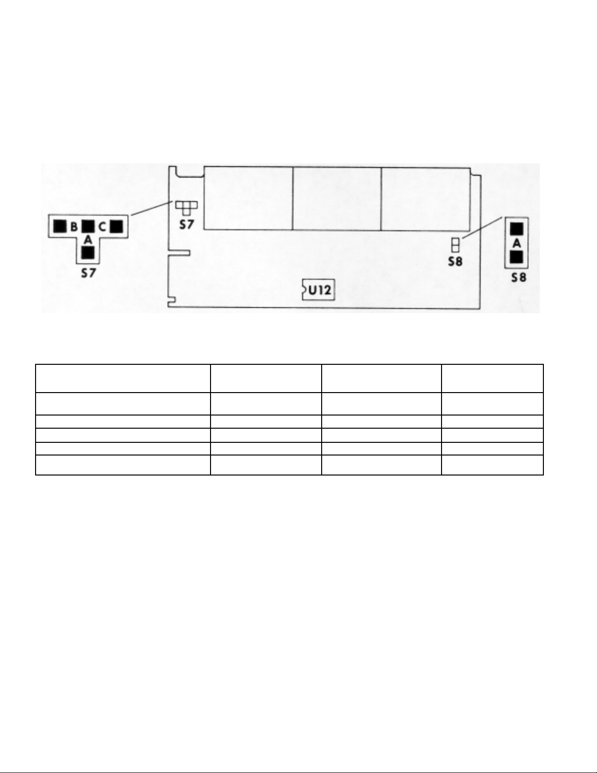
APPENDIX A
MODIFICATIONS - JUMPER DIAGRAMS
A.1 LOCKOUT FEATURES
Figure A-1 Display Board Jumper Locations
Function Locked Out Install Jumper Remove Jumper Notation
No Lock-out S7-C, S8-A Calibration S7-B, S8-A - Standard
Calibration S7-A, S8-A All items except setpoints S8-A S7-A, B,C
Disable front-panel buttons - S8-A S7 not affected
* Save in nonvolatile memory
1-25
Page 34
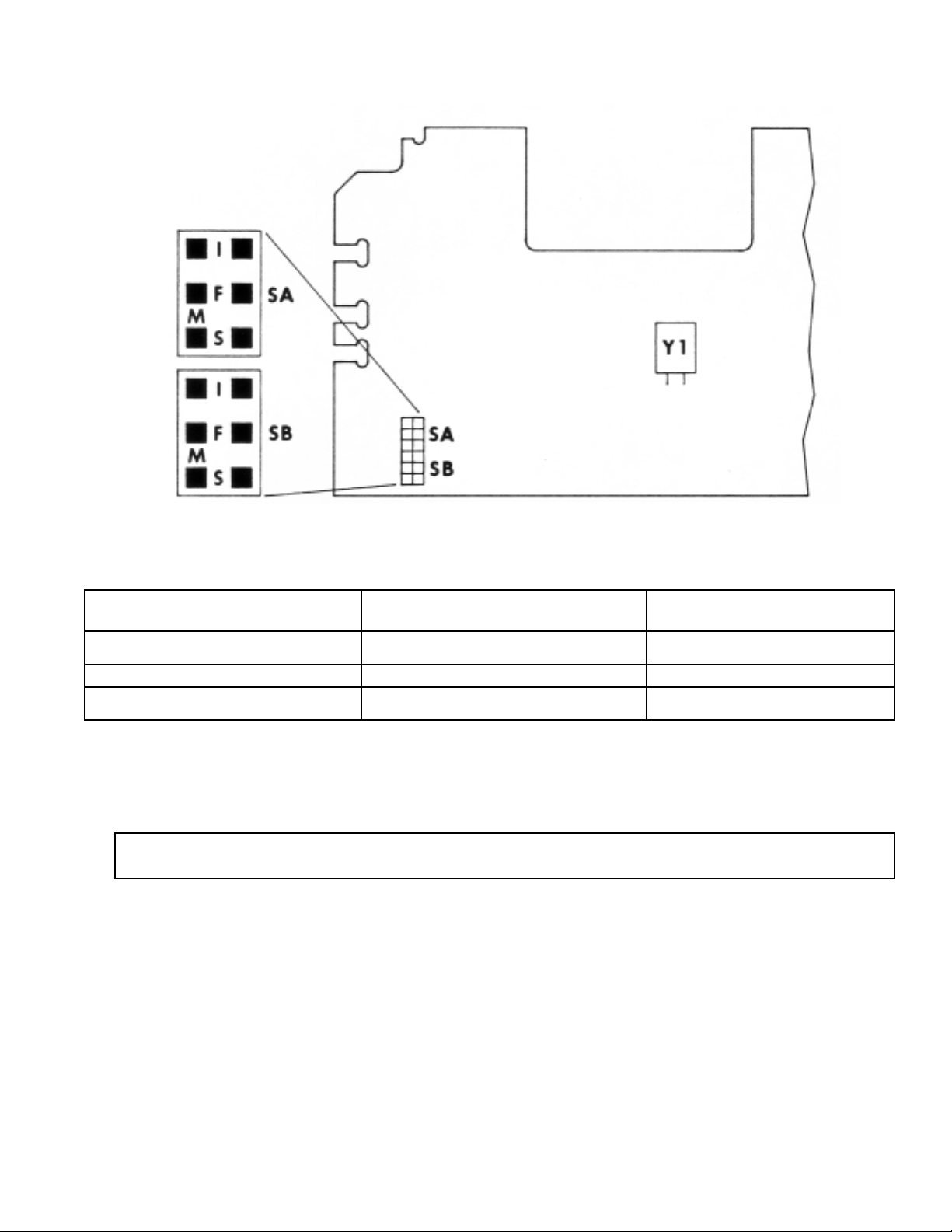
A.2 FREQUENCY RESPONSE
Figure A-2 Main Board Jumper Locations
Frequency Maximum Input Install Jumper
DC-7 MH (min) -.5 to +5.5 V SA-F, SB-F
DC-100 kHz (typ) -20 to +25 V SA-M, SB-M (standard)
DC-3 kHz (typ) -20 to +25 V SA-S, SB-S
For maximum noise rejection, select the lowest frequency response position that is
compatible with your input frequency.
NOTE: Jumpers installed on SA-I and SB-I connect the signal conditioner output.
1-26
Page 35
APPENDIX B
CONTROL INPUTS/OUTPUTS
All of the control I/O lines are located on P2, a 20-pin dual row header at the rear of the
counter. A 20-position mating mass-termination connector is an option (D20D). Alternatively,
a 34-pin mass-termination connector (industry standard) can be used to access both the I/O
and RS-232 lines.
RESET INPUT
This is a TTL/CMOS-compatible, low-true input with a 10 k Ohm pull-up resistor. A low level
of 2.2 milliseconds or more on this input resets the counter. If the function is Totalize, the
offset is displayed and the alarm outputs are updated according to the offset value. In other
functions, zero is displayed and the alarm outputs are reset regardless of the setpoint values.
All alarm outputs remain in the reset condition until the first measurement is completed.
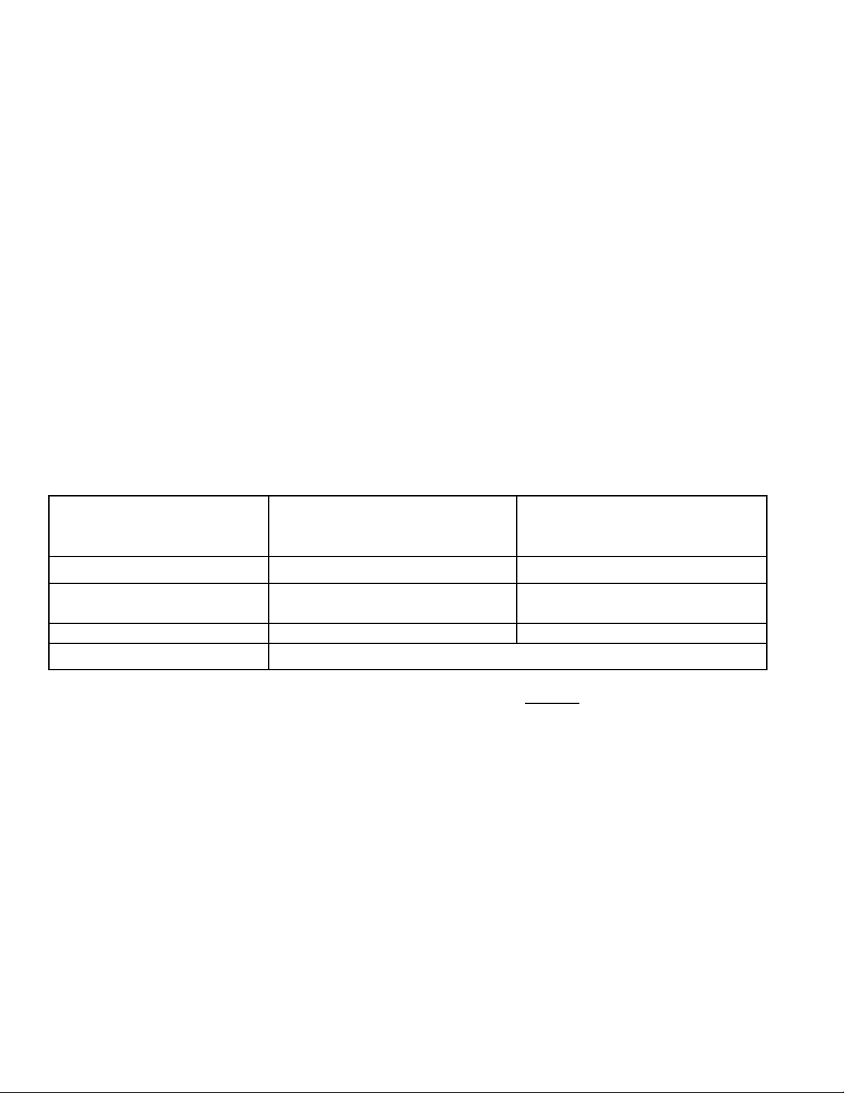
Table B-1 shows the effect of a reset pulse on the meter outputs. The meter can also be reset
by pushing the three center front-panel buttons simultaneously.
FREQUENCY, PERIOD
OUTPUT TIME INTERVAL, FREQ B/A TOTALIZE
Display Zero Offset
Hi, LO, and GO alarms Reset Updated according
(to high level) to the offset value
RS-232 No data is transmitted Offset is transmitted
Parallel BCD (Options) Updated according to the display and alarm outputs
Table B-1 Output Effect Immediately After RESET
1-27
Page 36

HOLD INPUT
Except in Totalize function, the P6000A does not start a measurement when the HOLD
input is low (HOLD is true). A high level (HOLD false) of 0.1 millisecond minimum at this time
starts and completes
a measurement.
In Totalize, the display is frozen and no ASCII data is transmitted when HOLD remains low for
a full reading cycle. If the HOLD input goes high for 0.5 millisecond anytime during the
reading cycle, the display is updated and ASCII data is transmitted. The parallel BCD data is
updated regardless of the HOLD input.
EXTERNAL GATE INPUT
This is a TTL/CMOS-compatible input with a 20 kOhm pull-up resistor. The polarity used is
normally positive (high true), but negative polarity can be selected by setting SS5 of
Configuration 1 (CnFG 1 = X1XXXX). When the meter function is Totalize, the A
input pulses can be gated with a signal on the External Gate input. Unlike conventional
counters, this gating does not introduce any error.
When the meter function is Frequency, Period, or Frequency Ratio, an external gate time
signal can be connected to this input instead of using the internal gate time. In this case,
SS6 of Configuration 1 should be set to disable the internal gate time (CnFG 1 = 1XXXXX).
The maximum allowed Gate Time in Frequency Ratio is 80 seconds. There is no maximum
limitation in Frequency or Period. Burst frequency measurement is possible, using an
external gate signal without disabling the internal gate time.
BLANK ENABLE INPUT/LINE FREQUENCY OUTPUT
The output is normally at high level with a 7.5 kOhm pull-up resistor. When the 50/60 Hz AC
power is present, two low-level pulses (about 3 milliseconds) appear on this output for each
AC power cycle. The signal can be tied to the A input for line frequency measurement (scale
factor = 0.5, multiplier).
This pin can also be used as an input. When tied to ground, it prevents display blanking in
case of an interruption in AC power. Connection of this input to a TTL or high speed CMOS
(HC Series) is not recommended since, in the presence of the AC power, it is pulled down
with a 301-ohm resistor twice per cycle.
1-28
Page 37

TEST OUTPUT - DIGIT 6
This is a TTL/CMOS compatible signal. The frequency of this signal is 400.0 Hz +.1% with
1/6 duty cycle. This output can drive 5 LSTTL loads.
NOTE: This is a display multiplex signal and must not be pulled down with a load of more
than .2 mA.
SPARE INVERTOR AND FLIP-FLOP
A TTL/CMOS compatible Schmitt trigger and a spare 'D' type flip-flop are provided on P2.
The inputs (clock, clear, and D) are CMOS compatible (HI level > 3.5 V, LO level < .9 V).
However, a 20 k pull-up resistor is provided on clear and D inputs to make them TTL at low
frequencies. This flip-flop can be configured to divide the clock frequency by two (connect Q
output to the D input), thus increasing the meter maximum operating frequency to 14 MHz.
ALARM LOW, HIGH, AND GO
These are open-collector outputs corresponding to LOW and HIGH setpoints (see
Section 4.1, Setpoints). Each output, if the alarm condition is active, can sink 150 mA.
When the alarm condition is inactive, an output can withstand 30 V.
1-29
Page 38

5.0 PROGRAMMING
5.1 GENERAL INFORMATION
The meter may be programmed using the three center pushbuttons (SET, ADVANCE and
ENTER) or by a personal computer through RS-232 port (connector A).
This instrument is designed to present a “serial menu” when “ENTER” pushbutton is pushed.
Pushing the appropriate button rolls the display through the meter functions, parameter
names and digits, repeating (for corrections) as often as desired.
This programming results in the active program by which the meter makes its measurements.
At the end of the programming sequence, the choice of ‘StorE/noStor’ is provided to allow this
active program to be preserved in the nonvolatile memory or to be used temporarily, keeping a
different program for later use in the nonvolatile memory. The stored program can become the
active program (discarding the one currently in operation) by simultaneously pushing both
RECALL buttons.
For security purposes, programming with front panel pushbuttons can be partially or completely
disabled by S7 and S8, the two lock-out jumpers on the display board, as described in Table 5-1
below.
S7 S8
POSITION POSITION MENU ITEMS LOCKED-OUT
C A All menu items available, no lock-out.
B A CALIB (Calibration Value) locked-out.
A A CALIB and STORE (Storing the program in
the non volatile memory) locked-out.
Removed A All menu items locked out except SP HI
(Setpoint High) and SP LO (Setpoint Low).
In these positions, and ENTER stores any
new value in both active and nonvolatile
memory.
Don’t Care Removed The programming pushbuttons are completely
disabled.
Table 5-1 Lock-Out Jumpers
2-1
Page 39
5.2 SELECTING THE FUNCTION TO BE PERFORMED
Apply power to the meter and the meter will briefly display the chosen function stored
in the nonvolatile memory, which becomes the active program upon power-up.
The counter now switches to Measurement mode (in about one second) if there are signa
pulses. To review or alter the programming, push ENTER. This will now display ‘Func’
instead of measurements. Repeated SET commands now roll the display through ‘FrEq’,
‘PEriod’, ‘ti Int’ (for time interval), ‘Fr b/A’ (Frequency Ratio B input divided by A input), and
‘totAL’ (for totalizing, e.g., counting). The desired one of these is selected by pushing
ENTER when it is displayed, moving you to scale factor selection.
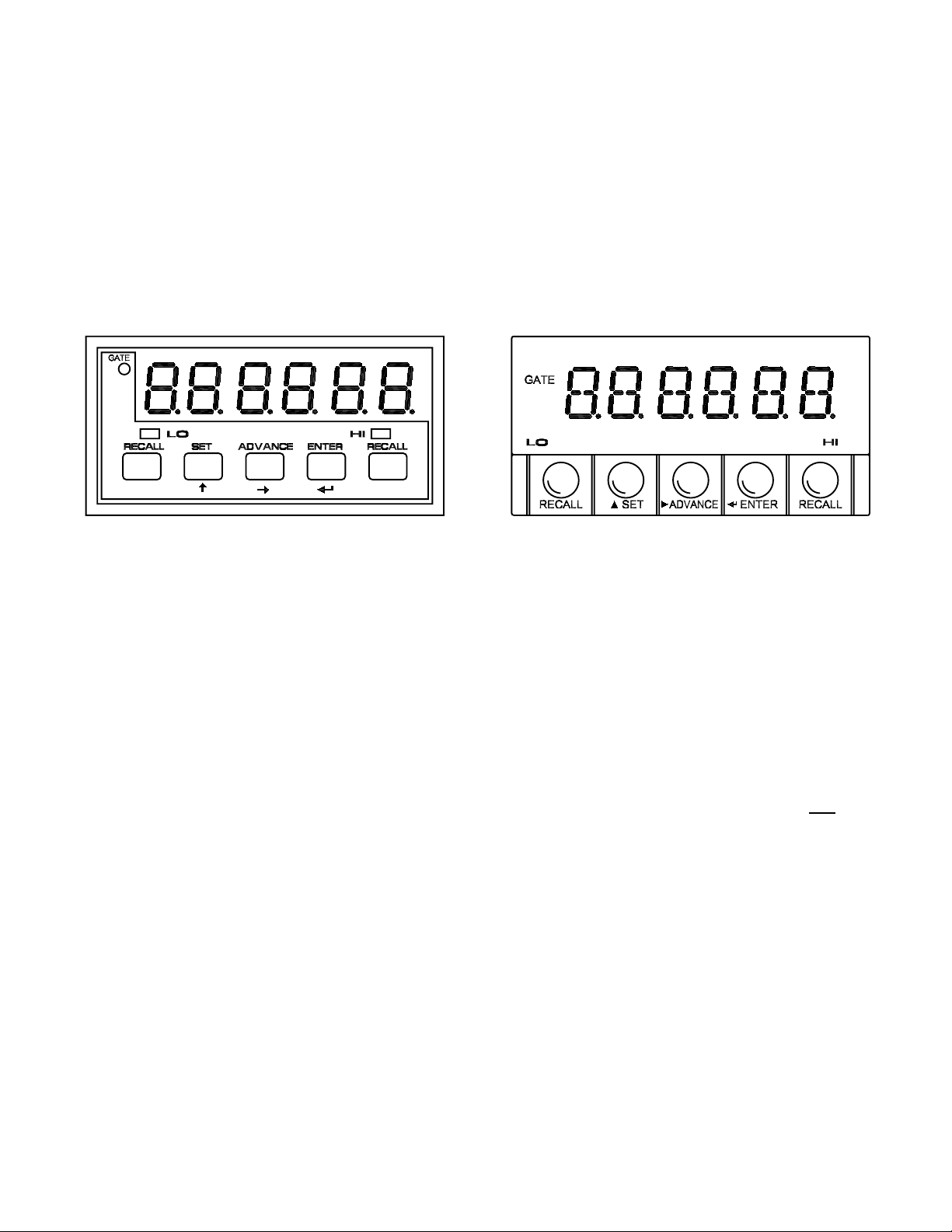
Front View - Classic Front View - Designer
If the function was already correct, you can move directly to scale factor with an ENTER
when ‘Func’ is displayed.
5.3 MULTIPLY OR DIVIDE BY A SCALE FACTOR
The input rate may be multiplied or divided by any desired scale factor from -.9.9.9.9.9. to
+9.9.9.9.9.9. with a decimal point selected in any position shown.
When ‘SCALE’ is displayed, pushing ADVANCE moves the display to either ‘A.SC’ or ‘A/SC’,
depending on which was in the program. To switch to the opposite, use SET, but do not
yet
push ENTER if you also wish to change the scale-factor numerical value or decimal location.
(If pushed in error, the menu can be rolled around to SCALE again by 11 ENTERs).
Another ADVANCE moves the value of scale factor onto the display, with the MostSignificant-Digit flashing (#6, on the left). If you wish to keep the scale factor as is, push
ENTER, and go to ‘OFFSET’. To change the MSD, push SET repeatedly until the desired
numeral is displayed. Push ADVANCE to move to the next-most-significant digit.
2-2
Page 40
Having altered or accepted all six digits of the scale factor, one more ADVANCE allows you
to reposition the decimal point, rolling it around with repeated SETs. When the decimal is
correct, ENTER keeps the value and the multiply or divide operator.
5.4 SELECTING AN OFFSET
The meter allows the scaled measurement value to be offset by any number from -99999
to +999999 with the decimal point in any position. Pushing ADVANCE when OFFSEt is
displayed moves the display to the offset value, which can be altered with the SET and
ADVANCE pushbuttons just like the scale factor discussed above. When the offset value is
correct, or to accept the value shown, push ENTER; this moves the display to rAnGE.
5.5 CHOOSING AUTO-RANGING OR FIXED DISPLAY DECIMAL-POINT LOCATION
When rAnGE is shown, ADVANCE displays the active-program choice, which will be either
Auto or six F’s with a flashing decimal point. The flashing denotes the location of the fixed
decimal point. The default position is FFFFFF. (d.p. = 1).
5.6 SELECTING RISING OR FALLING EDGE TRIGGERS FOR A AND B INPUTS
When SLOPE is displayed:
Push ADVANCE to display the current active program, which is A POS or A nEG. Another
ADVANCE will display the B input, B POS or B nEG. Push SET to change from positive to
negative or vice versa.
ADVANCE SET
A POS b POS A POS A nEG
NOTE: B input is not used with Frequency, Period or Totalize functions; therefore, ADVANCE
has no effect.
ENTER now displays setpoint selection.
Example 1:
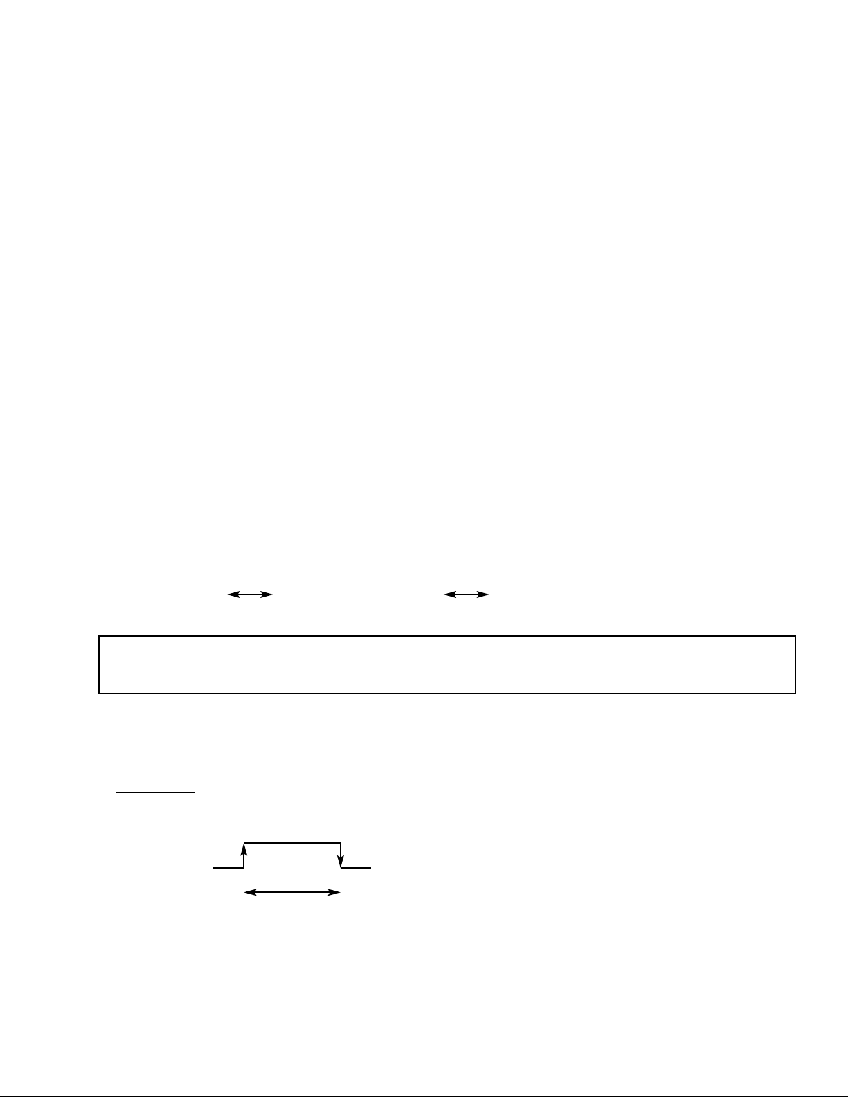
For a pulse width measurement, the time interval function (ti Int) should be chosen.
Rising Falling
Pulse Width
The positive and negative trigger slopes should be set for the A and B inputs, respectively.
2-3
Page 41
DO THIS DISPLAY SHOWS
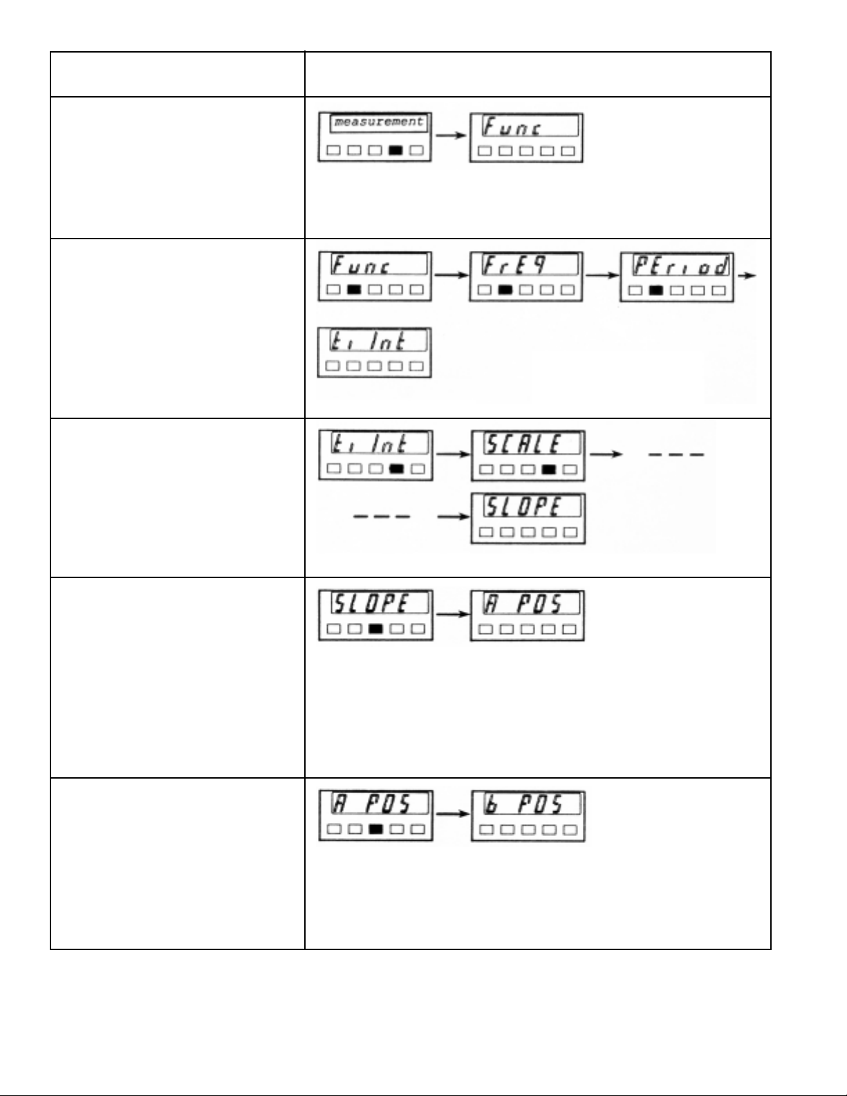
Push ENTER once.
Push SET three times
to set the function
to Time Interval.
Push ENTER four times
to select the slope.
Push ADVANCE once to
display the current
setting of A input slope;
can be changed with SET.
Push ADVANCE again
for B input slope.
2-4
Page 42
DO THIS DISPLAY SHOWS
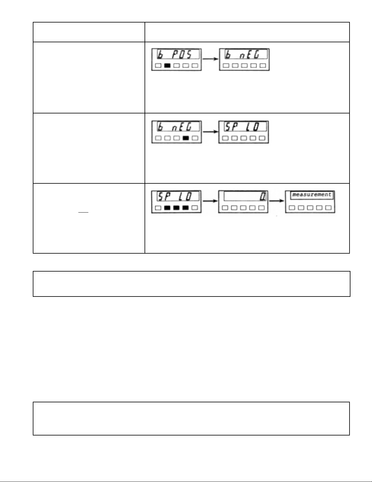
Push SET once for
negative slope.
Push ENTER once.
Push the three center
pushbuttons simultaneously.
(Be careful not
to push
SET first).
NOTE: The changes are not stored in nonvolatile memory and will be lost when the power
is turned off.
5.7 SETTING LOWER AND UPPER ALARM (or CONTROL) VALUES
SP LO is first displayed, and an ADVANCE will show its current value; this can be altered
like the scale factor (or offset) by use of ADVANCE and SET.
When correct, ENTER displays SP HI , and the value-changing routine is repeated. Another
ENTER moves you to gate-time selection.
High and low alarm outputs can be latched by setting the software switch SS4 of
Configuration 2 (XX1XXX). In this case the alarm output remains activated until a reset.
NOTE: Alarm outputs become active when display value exceeds the setpoint at least one
count. For precise setting, use the full meter resolution (e.g., 399.000 rather than
000399).
2-5
Page 43

5.8 SELECTING A GATE TIME
The measurement gate time is equal to this selection, from 00.00 to 99.99 seconds, plus a
small time allowance for computation/communication. (There is no gate time for totalizing,
so this choice is not displayed.)
When ‘GAtE t’ is displayed, ADVANCE shows the current value (00.30 is the default); it may
be altered with ADVANCE and SET (in 0.01 second increments). ENTER places that
chosen value in the active program.
5.9 CONFIGURATION #1 AND #2
The last ENTER moves ‘CnFG 1’ onto the display. Here, each digit represents a software
switch (SSW) and any or all of them may be reset. Alternate ‘1’ and ‘0’ are displayed with
SET, and ADVANCE selects the next right-hand digit, rolling around to the MSD after the
LSD (right- most digit).
After setting the six software switches of the CnFG 1, an ENTER command moves the
display onto CnFG 2. Again, any or all of the software switches of CnFG 2 may be set to ‘1’
or ‘0’ to enable or disable a feature.
The functions of these six software switches are described in Section 4.1 .
5.10 CALIBRATION OF THE CRYSTAL FREQUENCY (CALIb displayed)
This six-digit value is the ppm (parts-per-million) fine tuning of the crystal, and it is
examined/altered by ADVANCE/SET just as the other values discussed above. The default
setup locks out this item from the main menu (not displayed). To view or change the
calibration value, install jumpers on S7-C and S8 of the display board. To calibrate the meter:
1. Set the function to Frequency, the Gate Time to 01.00 second and the calibration value
to zero. Other setup parameters should be the same as the default setup (Section 4.4).
2. Connect a TTL-compatible calibration source frequency to the A input. SA jumper should
be on the F position.
3. Note the displayed value and calculate the calibration value as follows:
CALib = 1,000,000 X (
F input freq
- 1)
Display
4. Enter the calculated CALib and store it in the nonvolatile memory as described in the
following Section.
Another ENTER command moves the display to the last step, ‘noStor’.
2-6
Page 44

5.11 REPLACING THE STORED PROGRAM WITH THE ACTIVE PROGRAM
At this point, a complete active program has been defined. To use it and begin
measurements,
push ENTER in response to noStor. This active program may be quite
different from that stored in the nonvolatile memory. It will be discarded if power is
interrupted or if RECALL is used.
This active program may also replace the stored program so that it is automatically
restored upon power interruption. Push SET and ‘StorE’ will be displayed. Now an
ENTER writes the active program into the storage and starts measurements. The
previously stored program is discarded.
S7 on A position prevents storing the program in nonvolatile memory.
6.0 REMOTE PROGRAMMING
6.1 GENERAL INFORMATION
The meter contains a full-duplex RS-232 port for communications. It receives setup
commands and data and sends measurement values and current setup data. It operates
a either 1200 or 9600 baud, 7 data bits, even parity and 1 stop bit. It emulates DCE (data
communication equipment) and uses a handshake line while sending data, but none while
receiving data. A four-wire cable is the maximum required for communications:
Transmitted data
Received data
Request to send
Signal ground
When connected to a computer, such as an IBM PC, and one of four commands (Put, Get,
Write or Read) is received, the meter interrupts its program, receives the message, takes
appropriate action, and then starts over with a new measurement. No handshake is
required because the meter devotes its full attention to receiving the command data from
the computer.
In the other direction, the meter sends measurement and confirming setup data to the
computer under handshake (RTS) control. When the computer RTS output is true, data is
sent by the meter. When it is false, data is not sent. There are two modes of handshaking
when sending measurement data, message and character. In the Message Handshake
mode, the meter checks the RTS input from the computer when it is ready to send
measurement data. If the RTS is true, it sends the complete message data; if it is false, it
skips sending the data completely and continues with the next measurement. In the
Character Handshake mode, the program checks the RTS input before sending each
character and does not continue with the next measurement until the current measurement
has been completely sent.
2-7
Page 45
6.2 ASCII OUTPUT
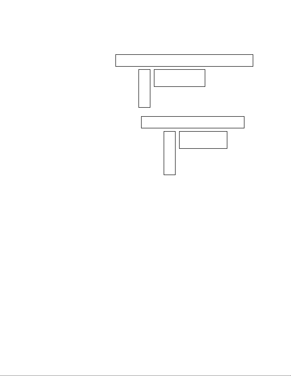
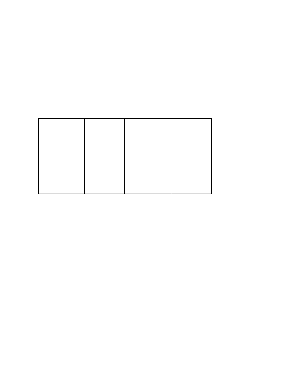
The meter sends measurement data according to the following fixed formats of 12
characters (CnFG 2 SSW #6=0) or 9 characters (CnFG 2 SSW #6=1). Each character is
sent as a 7-bit ASCII code character with even parity, and can be blank (ASCII 32) or as
shown below:
CHAR# 1 2 3 4 5 6 7 8 9 10 11 12
12-Character H 0 to 9, . (period), H Z (CR)
message SSW #6=0 (space), or -M S
of CnFG 2 B
or
L
CHAR# 1 2 3 4 5 6 7 8 9
9-Character H 0 to 9, . (period), (CR)
message SSW #6=1 (space), or -
of CnFG 2 B
or
L
6.2.1 12-Character Format
In this format, the first character provides alarm information.
H = high alarm
L = low alarm
B = both high and low alarms
space = neither high nor low alarms
The next 7 characters represent the measurement value as displayed on the front panel.
If positive, there are 6 digits and a decimal point; if negative, there is a minus sign with 5
digits and a decimal point. If leading zero suppression is selected, blanks are sent in place
of leading zeros. If the value overflows the 6-digit limit, it is sent in exponential format up
to a maximum of 9.99 E9 or -9.9 E9.
The next character is a space, followed by two units of measurement characters:
HZ for frequency
MS for period, time interval
2 spaces for frequency ratio, totalize
The final character is a carriage return.
2-8
Page 46
6.2.2 9-Character Format
The first 8 characters of this format are the same as in the 12-character format. The
space and the units of measurement (or spaces) are omitted. The carriage return is the
9th character and indicates the end of the measurement. The 9-character format is used
when a faster reading rate (and resulting shorter alarm response time) is more important
than units of measurement.
6.3 SETUP DATA
When requested by the commands ‘Get’ or ‘Read’, setup data is sent to the computer for
verification. Setup data is both sent and received as ASCII characters representing the
sixteen hex characters 0-9, A-F. Each hex character represents four bits or 16 pieces of
information. The 7-bit ASCII characters are shown with a leading even-parity bit.
Hex Character Bit Pattern Hex Character Bit Pattern
0 0011 0000 8 1011 1000
1 1011 0001 9 0011 1001
2 1011 0010 A 0100 0001
3 0011 0011 B 0100 0010
4 1011 0100 C 1100 0011
5 0011 0101 D 0100 0100
6 0011 0110 E 1100 0101
7 1011 0111 F 1100 0110
The setup data consists of a total of 42 nibbles of information that is sent and received in
the following order:
Meter Display
Parameter # of Nibbles
CALib Calibration 6
SP HI Setpoint High 6
SP LO Setpoint Low 6
OFFSEt Offset 6
SCALE Scale 6
GAtE t Gate Time 4
CnFG2 Configuration 2 2
CnFG1 Configuration 1 2
SLOPE Slope 1
rAnGE Range 1
Func Function 2
Each parameter is sent with the most-significant nibble first. Each bit may have
stand-alone significance or may be part of a binary number according to the following
formats.
2-9
Page 47
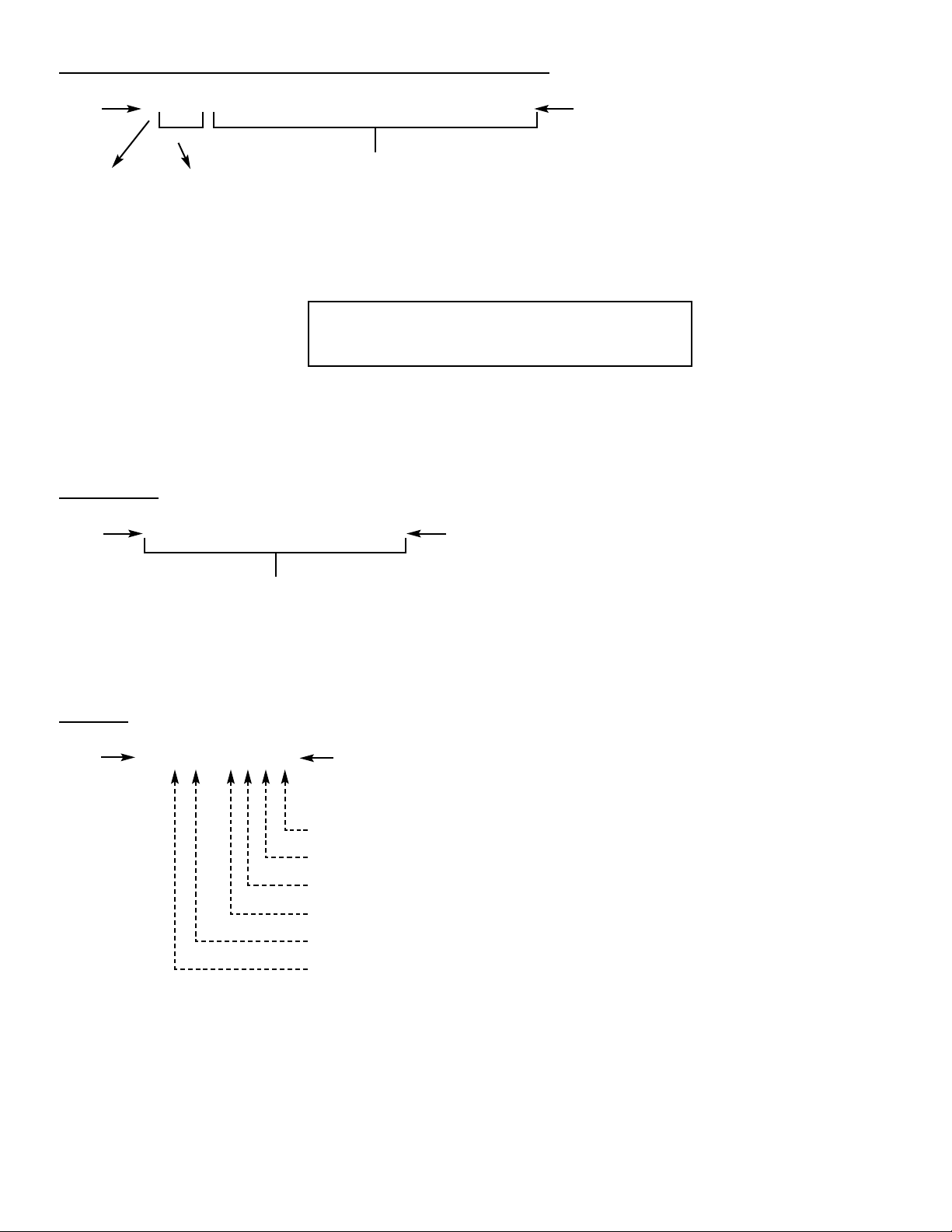
CALIB, SP HI, SP
LO, OFFSET, SCALE (6 Nibbles Each)
MS X XXX XXXX XXXX XXXX XXXX XXXX LS
Nibble Nibble
Polarity Coded Binary value of magnitude
0 = + Decimal
1 = - Point
Location
X.X.X.X.X.X.
6 5 4 3 2 1
DP 1 - 6
Example: A01000 = -0409.6
DP=2, - Polarity
GA
TE TIME
MS XXXX XXXX XXXX XXXX LS
Nibble Nibble
Binary value of magnitude in
hundredths of seconds
Example: 0100 = 2.56 sec
CONF 2
MS 0 0 X X X X X X LS
Nibble Nibble
1 = Display Dimming 50%
1 = Display Dimming 75%
1 = Parallel BCD Option
1 = Latching Alarms
1 = Make Low Alarm 2nd High Alarm
1 = Send no units of measurement
2-10
NOTE: The decimal point value cannot be
set 0 or 7; it must be 1 to 6.
Page 48
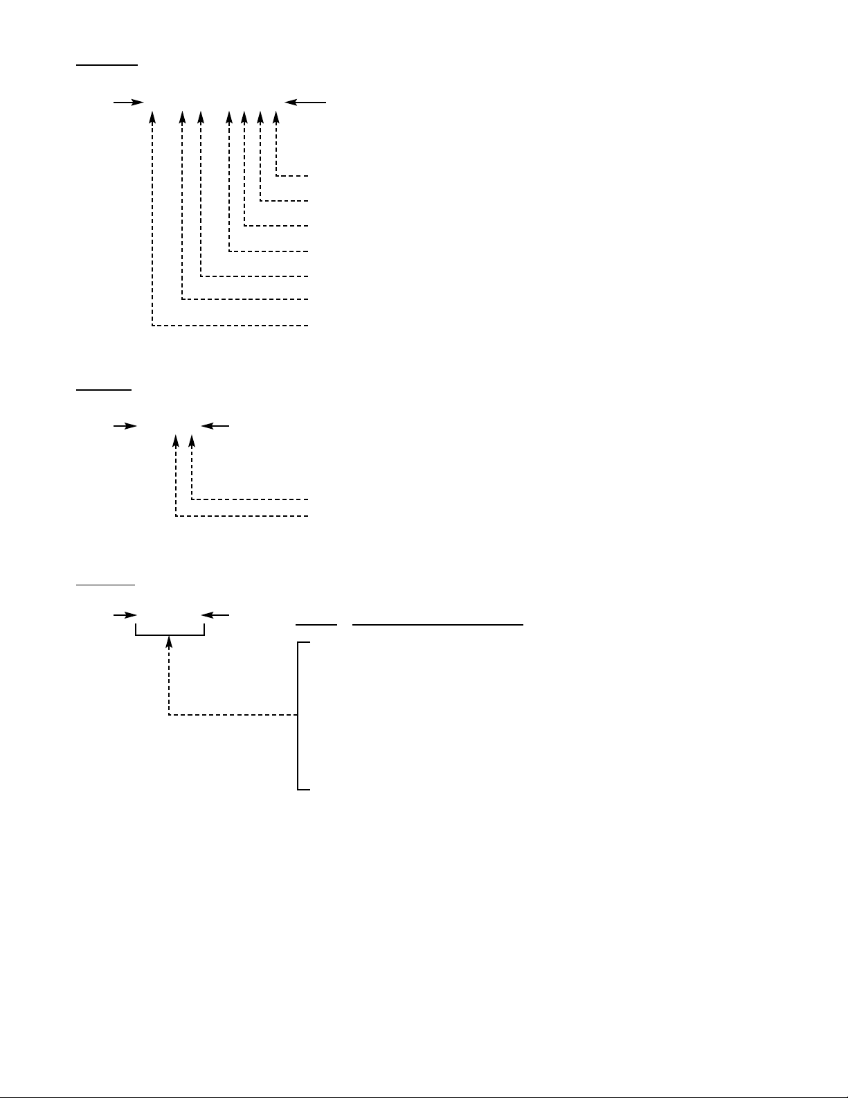
CONF 1
MS X 0 X X 0 X X X LS
Nibble Nibble
1 = No leading zero suppression
1 = 1200 baud (0 = 9600 baud)
1 = Character Handshake
Must be 0
1 = External Gate Negative Polarity
1 = Disable Internal Gate Time
SCALE Operation, 1 = Divide (0=Multiply)
SLOPE
MS 0 0 X X LS
Bit Bit
1 = A Negative Slope (0=Positive Slope)
1 = B Negative Slope (0=Positive Slope)
RANGE
MS 0 X X X LS V
alue Decimal Point Location
Bit Bit
0 Auto-range
1 FFFFFF. Right of digit 1 (LSD)
2 FFFFF.F Right of digit 2
3 FFFF.FF Right of digit 3
4 FFF.FFF Right of digit 4
5 FF.FFFF Right of digit 5
6 F.FFFFF Right of digit 6 (MSD)
2-11
Page 49
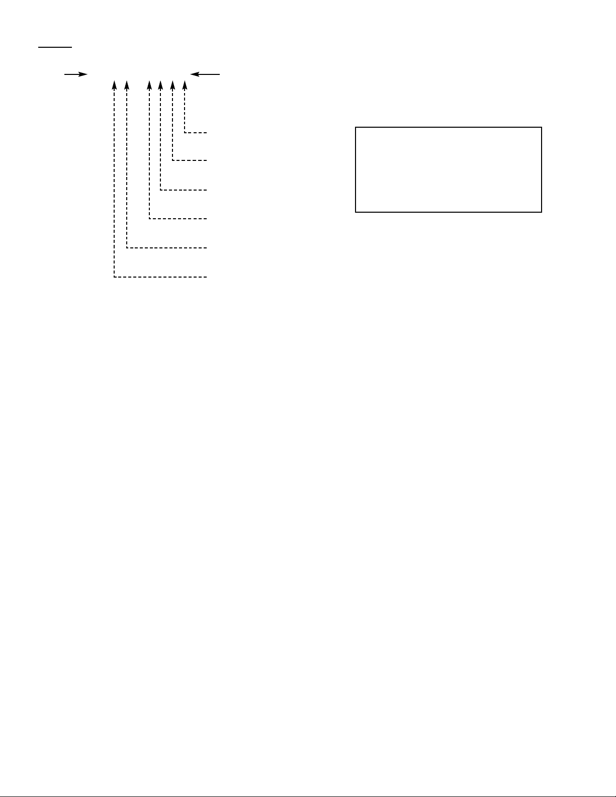
FUNC
MS 0 0 X X X X X X LS
Nibble Nibble
FREQ
PERIOD
TI INT
FR B/A
TOTALIZE
Zero Total (in TOTALIZE Only)
When received by the meter with the TOTALIZE bit, the Zero Total bit causes the value to be reset
to zero; otherwise, the TOTALIZE value is unaffected.
6.4 ASCII INPUT
The meter receives commands and setup data. Four commands may be received:
Put, Get, Write and Read. Each is a single letter preceded by the preamble string of three
characters @ U? . These characters have been selected to reduce the probability of noise
patterns generating an acceptable command. The Put command is followed by 42 hex
characters of desired setup data and all commands are terminated with a carriage return,
indicated by (CR).
@ U?PXXXXXXXXXXXXXXXXXXXXXXXXXXXXXXXXXXXXXXXXXX(CR)
@ U?G(CR)
@ U?W(CR)
@ U?R(CR)
The effect of the commands are described in the following paragraphs and in
Figure 6-3.
6.4.1 ‘Put’ Command @ U?P (setup data) (CR)
This command sends setup data to the meter, which receives it into its active memory and
then starts making measurements using the new setup parameters. This setup data is
replaced by that in nonvolatile memory if the power is cycled off and on or the Recall
pushbuttons activated.
2-12
NOTE:
One and only one bit
must be a 1, except for
TOTALIZE, which may
also have the Zero
Total bit set to a 1.
Page 50
6.4.2 ‘Get’ Command @ U?G (CR)
This command requests the meter to send the current setup parameters in the active
memory to the computer. It is normally used after the Put command to verify correct
reception of the setup parameters by the meter.
6.4.3 ‘Write’ Command @ U?W (CR)
This command transfers the setup data in the meter’s active memory (active program) to
nonvolatile memory (stored program). If it is desired to have a different program active
but not stored, this may be sent with a new ‘Put’ command or, if not locked out, entered
from the keyboard. Setup data in nonvolatile memory is then transferred back to the
active memory when power is cycled off and on or the Recall pushbuttons activated.
6.4.4 ‘Read’ Command @ U?R (CR)
This command requests the meter to read (transfer) the setup data in nonvolatile memory
into the active memory for use in the measurements that follow and to send this setup
data to the computer.
6.5 INTERFACING EXAMPLES
The meter can interface to any device with RS-232C communications. The output levels
are
+
5 V and the inputs may accept up to +25 V. The pin connections are labeled for the
meter to emulate DCE (Data Communications Equipment). Examples are given for
connections to an IBM PC with D-25 and D-9 connectors.
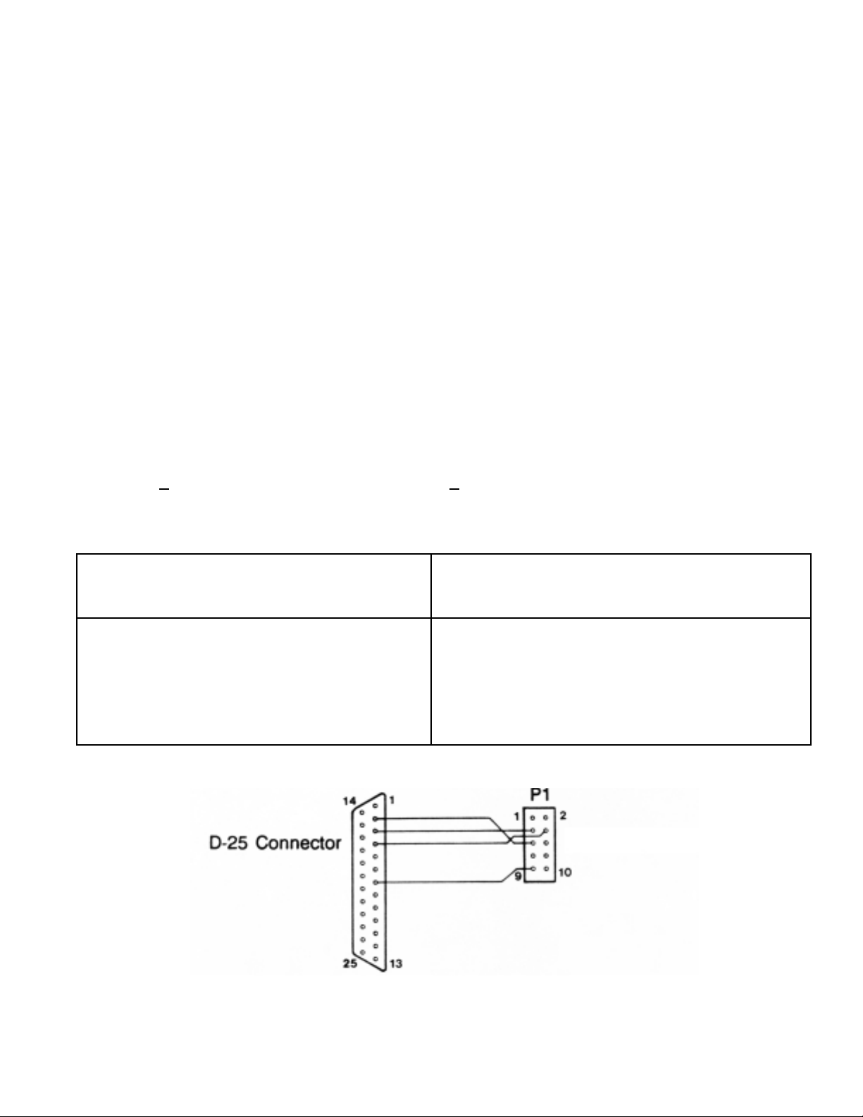
IBM PC (DTE)
D-25 Connector Meter (DCE)
Transmitted Data 2 P1-5 RS-232 IN
Received Data 3 P1-3 RS-232 OUT
Request to Send 4 P1-4 RS-232 RTS
Signal Ground 7 P1-9 GND
Figure 6-1 Connection of Serial Port to IBM Computer with D-25 Connector
2-13
Meter
Page 51
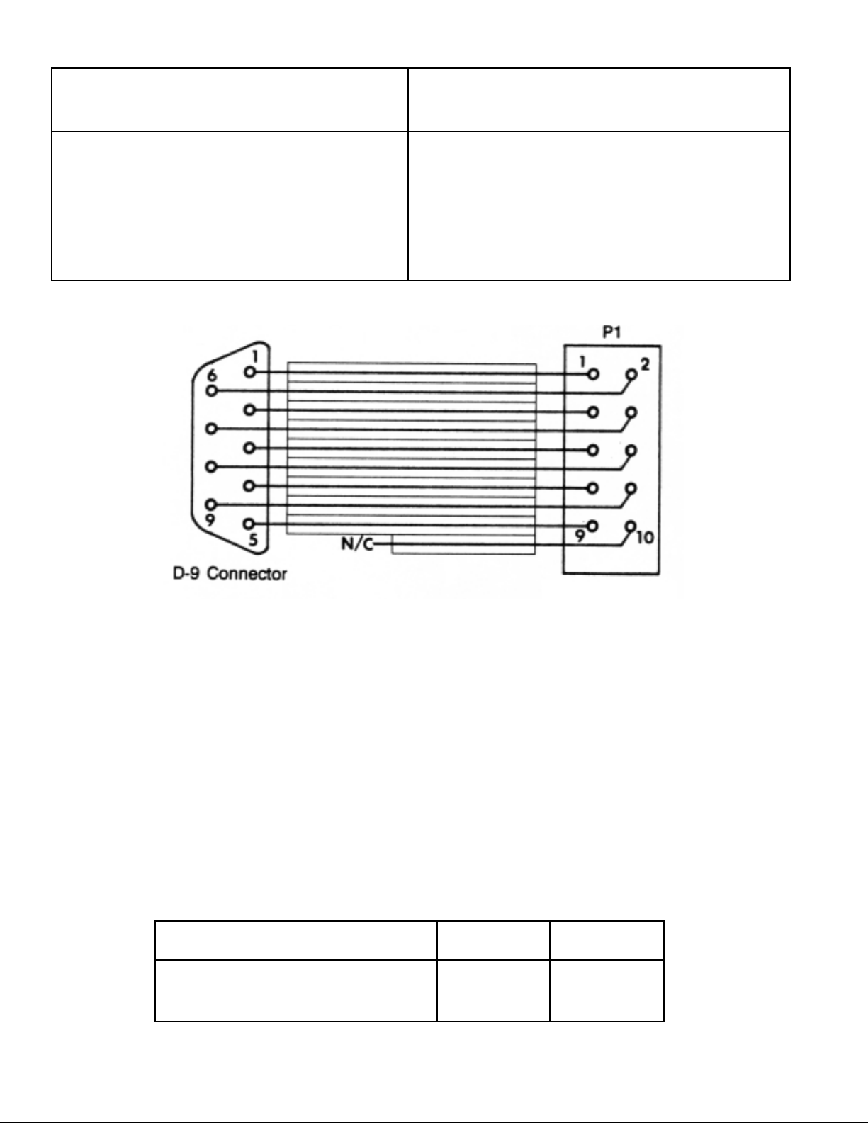
IBM PC (DTE)
D-9 Connector Meter (DCE)
Transmitted Data 3 P1-5 RS-232 IN
Received Data 2 P1-3 RS-232 OUT
Request to Send 7 P1-4 RS-232 RTS
Signal Ground 5 P1-9 GND
Do Not Connect P1-10 0-20 mA
Figure 6-2 Ribbon Cable and Mass Termination to Connect
Meter Serial Port to IBM Computer with D-9 Connector
See Programming Considerations, Section 6.6.2, for examples of IBM BASIC Program Statements
for communications.
6.6 PROGRAMMING CONSIDERATIONS
6.6.1 Baud Rate
If possible, it is recommended that 9600 baud be used for communi-cations instead
of 1200 since a faster reading rate is achieved when less time is spent communicating.
The time required to send measurements and receive setup data is:
9600 baud 1200 baud
Measurements (12 characters) 12.5 msec 50 msec
Setup data (43 characters) 45.8 msec 183 msec
2-14
Meter
Page 52

If the application program is to initiate communications with the meter and the initia baud
rate setting of the meter is unknown, it is possible to write the application program to
perform a Get command at 9600 baud rate. If that fails, change baud rate of the external
device to 1200 and try again. Once communication is established at the same baud rate,
it may be changed by sending new setup data with the desired baud rate.
6.6.2 Communication Control Programming
The following statements written in IBM BASICA are suggested for inclusion in an
application program written for the meter.
1. CLOSE 1: OPEN “COM1:9600,E,7,1,RS,CS,DS” AS #1
This opens the IBM communications file for 9600 baud, even parity, 7-bit word and 1 stop
bit. RTS is made false to begin with and the CTS and DSR handshake lines are ignored.
Two stop bits could also be used but would only lengthen the communications time. If the
IBM communications port is COM2, change COM1 above to COM2 and 3FC to 2FC in 2
and 3 below.
2. 3000 OUT &H3FC,INP(&H3FC) AND &HFD:RETURN
This subroutine resets the RTS output of the IBM to low (false). RTS false prevents the
meter from sending readings.
3. 3100 OUT &H3FC,INP(&H3FC) OR &H02:RETURN
This subroutine sets the RTS output of the IBM to high (true). RTS true allows the
P6000A/P5000 to send readings.
4. 4000 IF LOC(1)=0 THEN 4030
4010 ON ERROR GOTO 4040
4020 A$=INPUT$(LOC(1),#1)
4030 ON ERROR GOTO 0:RETURN
4040 RESUME 4000
This subroutine empties the input buffer, and does it without a program-terminating error
whenever the buffer is full. If the statement on line 4020 is executed by itself when the
buffer is full, an error is generated.
5. PRINT #1, ‘@U?P’ + SETUP$
This sends the setup data of 42 hex characters in SETUP$ to the meter.
2-15
Page 53

6. PRINT #1, ‘@U?G’
PRINT #1, ‘@U?R’
The first statement requests that the setup data be sent from the meter to the IBM computer.
The second statement requests that the setup data be transferred from nonvolatile memory
to active memory before being sent.
7. PRINT #1, ‘@U?W’
This writes (transfers) data from the meter’s active memory to the nonvolatile memory.
8. 1000 GOSUB 4000 ‘EMPTY INPUT BUFFER
1010 B$=’’’’ ‘HOLDS CUMULATIVE INPUT DATA
1020 GOSUB 3100 ‘MAKE RTS TRUE TO START P6000A
SENDING DATA
1030 IF LOC(1)=0 THEN 1030 ‘WAIT FOR DATA
1040 A$=INPUT$(LOC(1),#1) ‘GET DATA FROM INPUT BUFFER
1050 B$=B$+A$ ‘CONCATENATE CHARACTERS
1060 CR=INSTR(B$,CHR$(13)) ‘FIND LOCATION OF CARRIAGE RETURN
1070 IF CR=0 THEN 1030 ‘IF NOT RECEIVED YET, REPEAT
1080 A$=LEFT$(B$,CR-1) ‘THE VALUE IS ALL CHARS UP TO THE
CARRIAGE RETURN
1090 GOSUB 3000 ‘MAKE RTS FALSE TO STOP P6000A FROM
SENDING DATA
This reads the data sent from the meter to the IBM PC.
9. To read data continuously, add the following:
1100 B$=MID$(B$,CR+1) ‘STRIP THE READING FROM THE STRING
1110 GOSUB XXXX ‘DO SOMETHING WITH THE DATA IN A$
1120 GOTO 1020 ‘READ MORE DATA
2-16
Page 54

To read the meter output from the computer screen, use the following program which was
written in IBM BASICA.
10 ‘ READ.BAS
100 SCREEN 0:CLS:KEY OFF:CLOSE
130 CR$=CHR$(13)
160 PRINT:PRINT “SET THE P6000A/P5000 TO 9600 BAUD.”
180 PRINT:INPUT “ENTER COM1 (1) OR COM2 (2) RS-232 PORT “;W
185 PRINT:INPUT “INCLUDE UNITS OF MEASUREMENT (Y/N) “;K$
186 IF (K$ = “Y” OR K$ = “y”) THEN LN = 11 ELSE LN = 8
190 IF W=1 THEN COMM$=”COM1” ELSE COMM$ = “COM2”
500 ‘ ======================= Open serial communications
530 CLOSE:OPEN COMM$+”:9600,E,7,1,CS,DS” AS #1
540 CLS
1000 ‘ ======================== Start main program
1010 GOSUB 5030 ‘CLEAR INPUT BUFFER
1050 IF INKEY$=CHR$(27) THEN 2000
1060 IF LOC(1)=0 THEN 1050
1070 A$=INPUT$(LOC(1),#1) ‘READ RECORD
1080 B$=B$+A$
1090 Q=INSTR(B$,CR$)
1100 IF Q=0 THEN 1050
1110 A$=LEFT$(B$,Q-1)
1120 B$=MID$(B$,Q+1)
1130 IF LEN(A$) < > LN THEN 1050
1150 PRINT A$
1160 GOTO 1050
2000 ‘ ========================
2010 PRINT “ESC=EXIT CR=CONT “;
2020 PRINT “?”;
2030 KY$=INKEY$:IF KY$=CHR$(27) THEN 2080
2040 IF KY$=CHR$(13) THEN CLS : GOTO 1010
2070 IF KY$=”” THEN 2030
2080 CLOSE :SCREEN 0:END ‘ ============ Exit here
5000 ‘********************************************
5010 ‘* CLEAR INPUT BUFFER *
5020 ‘********************************************
5030 IF LOC(1)=0 THEN 5060
5040 ON ERROR GOTO 5070
5050 A$=INPUT$(LOC(1),#1)
5060 ON ERROR GOTO 0:RETURN
5070 RESUME 5030
To change the meter’s setup data or to monitor the readings, use the SB02 Option which
provides a complete menu-driven program.
2-17
Page 55
6.7 PARITY CHECKING
Although the meter includes an even parity bit with data sent out on the RS-232C interface,
it does not check the data received for even parity.
6.8 TIMING
When a Put command is sent to the meter, it is accompanied by a string of 42 setup
characters. The statement PRINT #1, @U?P + SETUP$ puts the string into an output buffer
for transmission and the BASIC program continues while the data is being transmitted. If
within a few lines, the statement PRINT #1, @U?G is executed, the @U?G is added to the
end of the setup string in the buffer which is still being transmitted. This causes the @U?G
characters to be missed because each transmission from the computer must be completely
received by the meter and the next measurement started before another command is issued.
A statement FOR J=1 TO 300:NEXT J introduces enough delay to allow separation between
commands.
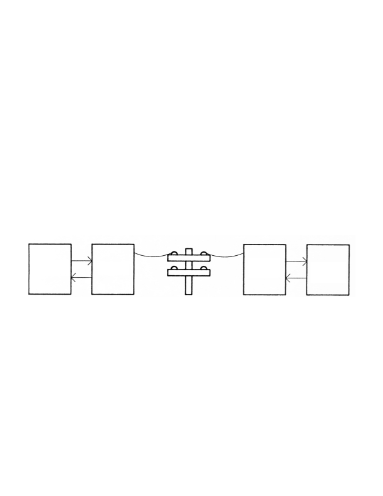
6.9 MODEM OPERATION
The meter can be connected to a freestanding modem, such as the Hayes Smartmodem
1200, so that data can be transmitted and received over phone lines. A typical controller
would be an IBM PC with a Hayes Smartmodem 1200B plug-in modem.
Figure 6-3 Modem Concept
Using a rate of 1200 baud, measurement data can be received by the computer from the
meter and setup data can be sent to the meter from the computer. By using an autoanswering modem connected to the meter, data can be gathered from a remote location
upon demand. If a command is sent to the meter at 1200 baud while the meter’s active
memory is programmed for 9600 baud, the meter will automatically switch to 1200 baud.
This prevents the modem application from being disabled when a setup parameter of 9600
baud is accidentally sent to the meter.
6.10 0 - 20 mA, ASCII OUTPUT
When closed, solder switch J connects a 249 ohm pull-up resistor to this open collector
output, providing a 20 mA current source for the 0 - 20 mA, ASCII output. This output can
be used over longer distances than the RS-232 output.
2-18
Meter
Modem
Modem
Computer
Page 56
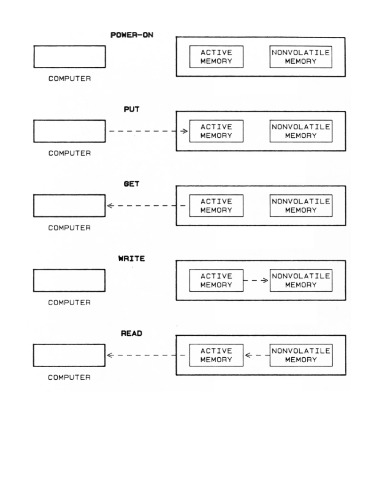
Figure 6-4 Programming Commands
2-19
Meter
Meter
Meter
Meter
Meter
Page 57

7.0 TROUBLESHOOTING CHART
Your meter is a powerful, universal counter with a wide range of programming parameters.
An error in the programmed parameters can cause the counter to provide unexpected
results. Before requesting service, please read this troubleshooting chart.
SYMPTOMS ACTION TO TAKE OR EXPLANATION
Display Blank Check the power connections. For battery-powered
(completely) units, connect the BLANK ENABLE input (pin 16 of P2)
to the GND.
Push the two RECALL buttons simultaneously or turn off the
power for 20 seconds.
Display shows the Check the input connections, levels, and jumpers
functions, e.g., FrEq (SA and SB). The input signal(s) may be missing.
and does not advance The Gate Time may be too long. The Internal Gate Time
to show a measurement. may be disabled (SSW #6 of the Configuration Word 1
should be 0XXXXX).
The External Gate Polarity may be reversed (SSW #5,
Configuration Word 1). HOLD input (pin 13 of P2) might be
held low.
Display reads zero Push the two RECALL buttons simultaneously. If display still
reads zero, use Auto-range. The scale factor may be a small
multiplier (including zero) or a large divider. RESET input
may be low.
Display shows an Push the two RECALL buttons simultaneously or turn off
illegal character the power for 20 seconds.
(not in glossary)
Display in exponential If the digital following the E is 5 or smaller, use the
format, e.g., 1.23 E6 Auto-range. If it is 6 or greater, use a larger divide or
(Overflow indication) smaller multiply scale factor and Auto-range.
2-20
Page 58
SYMPTOMS ACTION TO TAKE OR EXPLANATION
One or more digits The counter may be in the programming mode. Push the
are flashing. three center pushbuttons to reset the counter. If the display
is still flashing, reset SSW #4 of Configuration 1 to zero
(XX0XXX).
Leading zeroes are Set the SSW #1 of Configuration 1 to zero (XXXXX1).
blank
Leading zeroes are Reset the SSW #1 of Configuration 1 to zero (XXXXX0).
not blank
Reading is incorrect Check the function, scale factor, offset, slope
(in Time Interval only) and Calibration Factor.
Programming push- Check the lock-out jumper on S8. RESET input might be
buttons don’t work at all held low.
Programming push- Check the lock-out jumper on S7.
buttons don’t work
properly
The least-significant The signal source may not be stable enough.
digit(s) bouncing
Display does not The HOLD input (pin 9 of P1) might be held low.
update Inputs may be disconnected. Gate Time may be too long.
NOTE: In setting the software switches (SSW) of Configuration 1 and 2, “X” represents
“don’t care” which means that either 0 or 1 may be selected to disable or enable
other features.
2-21
Page 59

8.0 SPECIFICATIONS
8.1 GENERAL INFORMATION
Programmable Functions: Frequency, Period, Time Interval A to B,
Frequency Ratio B/A, Totalize
Scale Factor: -99999 to 999999 with a choice of six
decimal point positions (9.9.9.9.9.9.),
multiply or divide
Offset: -99999 to 999999 with a choice of six
decimal point positions (9.9.9.9.9.9.)
8.2 INPUT CHARACTERISTICS
Max Frequencies (A and B SA and SB on F positions: 7 MHz (min)
inputs square wave,
0 to +5 V): SA and SB on M positions: 200 kHz (typ)
SA and SB on S positions: 3 kHz (typ)
Trigger Slopes (A and B): Positive or Negative, programmable
Input Threshold: All TTL and CMOS compatible except
spare flip-flop inputs, which are:
5 V, CMOS compatible (Low = less than
0.9 V, High = more than 3.5 V )
Input Impedance: A, B and External Gate inputs:
20 k pull-up
HOLD input: 100 k pull-up (typ)
RESET input: 10 k pull-up
Max Input Voltage : SA and SB on F positions: -0.5 and +5.5 V
(A and B)
SA and SB on M or S positions: -20 and +25 V
Max Input Voltage : -0.5 and 5.5 V
(all other inputs)
2-22
Page 60

8.3 DISPLAY
Type: “Classic” Case: 7-segment, orange LED with red lens
“Designer” Case: 7-segment, orange LED with gray
lens
Digit Height: 14.2 mm (.56 in)
Symbols: -.8.8.8.8.8. and 8.8.8.8.8.8.
Decimal Point: Six positions; programmable
Fixed or auto-ranging
Leading Zeros: Blank or displayed; programmable
Overflow Indication: Display in exponential format to 9.99 E9
Update Time: Averaging time + (10-40 milliseconds) +
communication time
Brightness: 100%, 50%, 25%; programmable
Displayed Value: (Measurement · Scale Factor) + Offset
Indicator Lights: GATE LED; Low and High alarm LEDs
Capacity:
decimal format -99999 or 999999
exponential format -9.9 X 10⁹or 9.99 X 10
9
8.4 OUTPUT CHARACTERISTICS
Lo, Hi and Go Alarm Outputs: Open-collectors, active low, 150 mA at 1 V
Digit 6: High level = 3.5 V at 100 µA
Low level = 0.4 V at 1.6 mA
Frequency = 400 Hz
+
.1%
8.5 TIME BASE
Internal Clock Reference: 11.059 MHz
Stability:
+
50 ppm over 0-60°C range
Fine-Calibration method: Programmable calibration value
Calibration accuracy at 25°C:
+
2 ppm
2-23
Page 61

8.6 COMMUNICATION
RS-232 OUT, IN and RTS: RS-232 C compatible with transmit
handshake line (RTS)
Levels:
+
5 V
Transmitted data: Alarm + 6 digits + decimal point + CR
(9 characters)
or
Alarm + 6 digits + d.p. + space + units
of measurement + CR (12 characters)
Baud rate: 1200 or 9600 baud, programmable
Received data: Complete setup parameters, no handshake
0-20 mA ASCII out: Open collector (data the same as
RS-232 OUT)
Bit serial BCD (Internal
connection to parallel
BCD board): 32 bits; display and alarm data. When enabled,
takes about 10 milliseconds to be transmitted.
8.7 FREQUENCY/PERIOD FUNCTION
Frequency range: 10
-6
Hz to 7 MHz (140 nsec to 36 days)
Nominal Gate Time (NGT): 00.00 to 99.99 seconds
Averaging Time (Actual Gate Time): (NGT + 2.7 ms) or Ext. Gate Time + time to
complete the last period
10
Max Ext. Gate Time: 6 X 10 or 36 days, whichever is less
F
A
Units-of-Measurement
(Scale Factor = 1): Frequency: hertz
Period: milliseconds
Accuracy at 25°C:
+
1 LSD +2 ppm of input
(Auto-range SA on F Position)
2-24
Page 62

Calculation time: Scale Factor is a multiplier; 20-35 ms
Scale Factor is a divider; 30-45 ms
Max speed (gate time minimum)
(Parallel BCD disabled,
RTS false): 20-40 readings/second
8.8 TIME INTERVAL
Interval range, A to B: 400 ns to 36 days
Trigger error (A - B): SA and SB on F positions: +30
+
70 ns
SA and SB on M positions: +30 +250 ns
SA and SB on S positions: +9 µs
Accuracy, NGT = 00.00:
+
1 LSD +trigger error +TI (Time Base Error)
Accuracy, NGT = 00.00:
+
1 LSD +trigger error +(T.B. Error) TI
√N
where N is number of averaged intervals
Number of averaged intervals: N = (A
veraging T
ime) X Frequency
2
Nominal Gate Time (NGT): 00.00 to 99.99 seconds, in .01 sec steps
Averaging time: NGT = 00.00: .1 ms + time to complete
the last interval
NGT = 00.00: NGT + 2.5 ms + time to
complete the last interval
Averaging method: Every other Time Interval
Unit of Measurement:
(Scale Factor = 1) milliseconds
8.9 FREQUENCY RATIO,
B
A
B input frequency range: 0.007 Hz to 7 MHz
A input frequency range: F
B
> 5 kHz: 10-6Hz to 7 MHz
F
B
< 5 kHz:
1
+ 1
< 160 sec
F
A
F
B
Nominal Gate Time (NGT): 00.00 to 99.99 seconds, in .01 sec steps
2-25
Page 63

Averaging time: (NGT + 2.5 ms) or Ext. Gate Time + time to
complete the last period of A and B
Resolution: FB > 5 kHz:
1
(SA and SB on F positions)
(Averaging Time) X F
B
FB < 5 kHz:
1
5000 X (Averaging Time)
10 13
Max External Gate Time: 6 X 10 or 3.5 X 10 , whichever is less
F
A
F
B
8.10 TOTALIZE
Count direction: Up or Down (determined by sign of scale factor)
LSD: 1 count of the input
(Auto-range, Scale Factor=1)
10
Internal count capacity: (60,000,000,000) 6 X 10 counts
AC power failure provisions: Display value stored in nonvolatile memory and
restored with power
8.11 POWER
+5 V output: Regulated, 50 mA max in nontotalize modes (1)
(reduced by upper-board option)
V+ output: Unregulated, 6-9 V, 50 mA max in nontotalize
modes (1)
(reduced by upper-board option and current drawn
from the +5 V output)
AC voltage (standard): 115 or 230 V ac
+
10%
47 to 400 Hz
Power consumption: 7.5 W max.
Battery backup: 6-12 V, 50 mA (typ), without upper-board
(connected to V+ with a diode) option
NOTE: In Totalize Mode, 10 mA can be drawn from +5 V or V+ when display brightness is
normal or dim (CnFG 2 = XXXX1). Up to 50 mA can be drawn if the BLANK
ENABLE input is tied to GND. This prevents a power failure detection.
2-26
Page 64
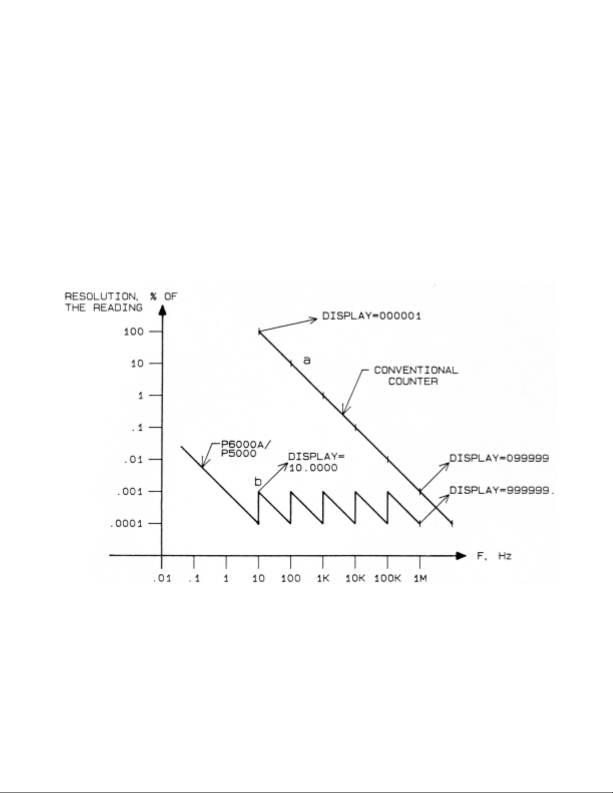
APPENDIX C
THEORY OF OPERATION
FREQUENCY AND PERIOD
To display the input frequency in Hz, a conventional counter simply counts the input pulses
(cycles) during a 1-second gate time and displays the result without any change. The
meter counts both the input pulses and the internal clock pulses during a programmable gate
time and calculates the frequency. As a result, the display resolution is not limited by the
input frequency. One-tenth of a second of gate time is enough for 6-digit resolution. (Figure
C-1 compares the resolution of a conventional counter with .1 second gate time with the
meter resolution.)
Figure C-1 Resolution Comparison of meter to Conventional Counters
2-27
Page 65
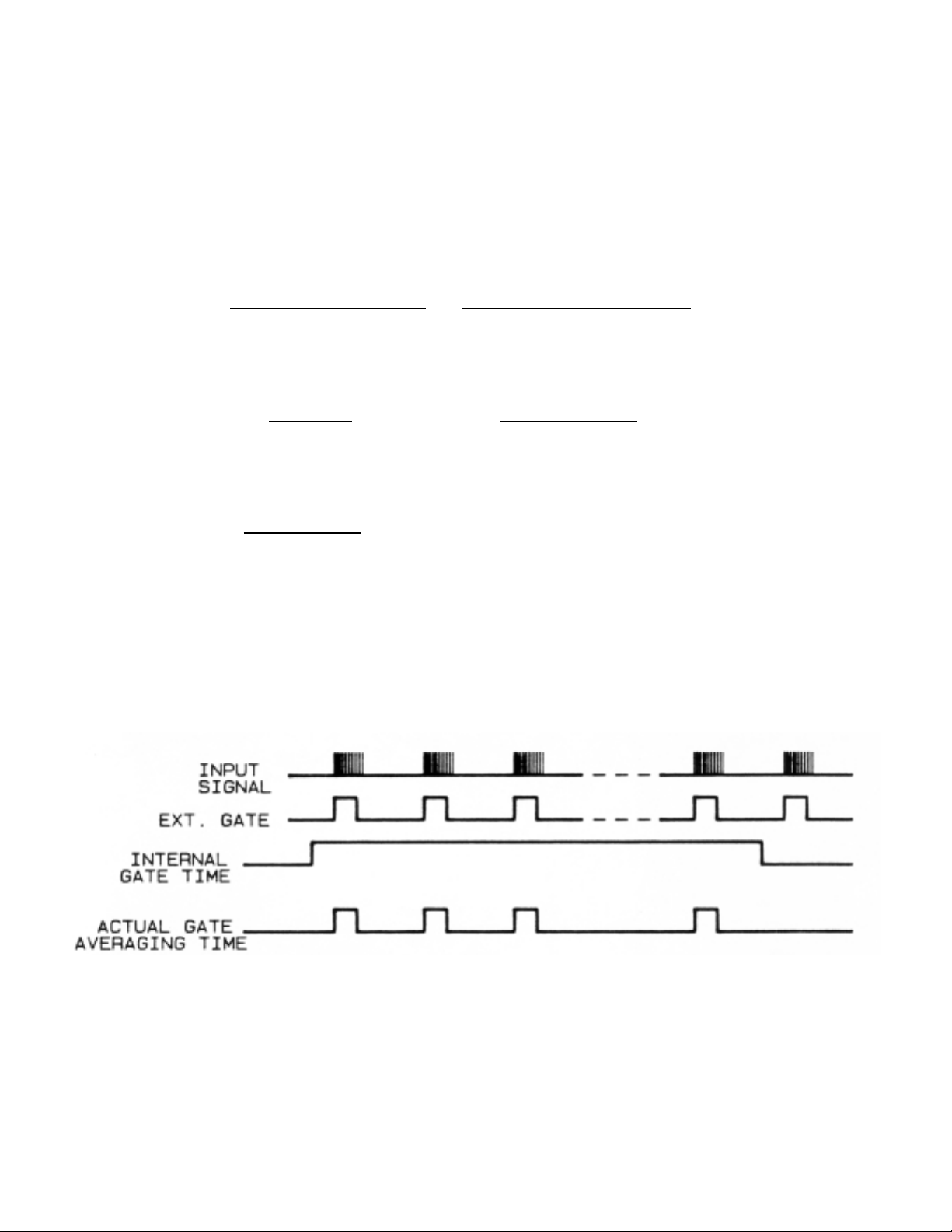
Gate Timing:
The meter starts a frequency/period measurement by arming the A flip-flop. Then, the first
trigger slope of the A input sets this flip-flop and opens the A and B gates, permitting the
input pulses and the 11.059 MHz internal clock to be counted by the A and B counters,
respectively. After the gate time is over, the meter disarms the A flip-flop; and the next
trigger slope of the input resets the flip-flop and closes the A and B gates. At this time, the
meter reads the A and B counters and calculates the frequency or period.
Frequency =
Number of Input Pulses
=
Counter A
Averaging Time Counter B/Clock Frequency
Frequency, Hz =
Counter A
(11.059 X 10⁶) (
Calibration Value
+1 )
Counter B 1000000
Period, ms =
1000
Frequency, Hz
When using an external gate time, the timing is the same except that after arming the
flip-flop, the meter waits until the external gate signal disarms the flip-flop and the next
input pulse closes the A and B gates. Burst Frequency Measurement is possible using the
external gate input without disabling the internal gate. The timings are shown below in
Figure C-2.
Figure C-2 Burst Frequency Measurement
The external gate signal must be active only when the input signal is valid.
2-28
Page 66
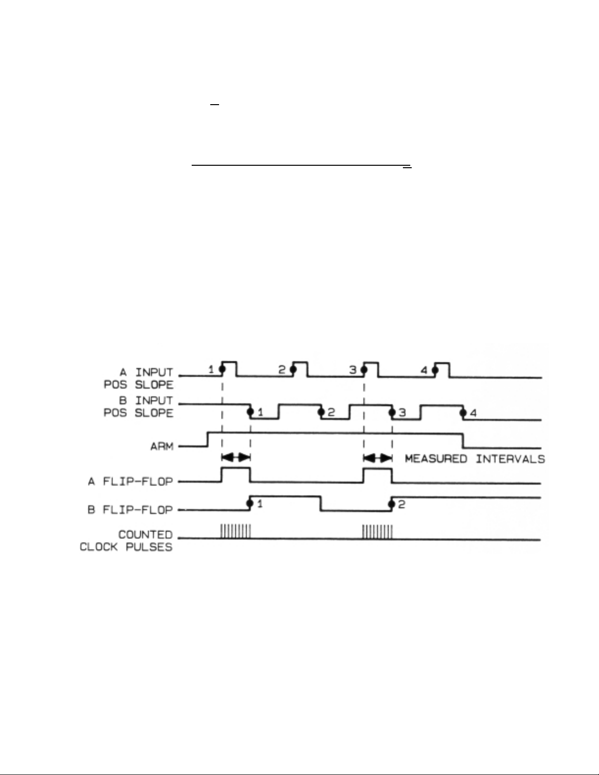
TIME-INTERVAL MEASUREMENT (A TO B)
The meter measures the time interval from the trigger slope of the A input to the
trigger slope of the B input and displays the result in milliseconds. If the Nominal Gate Time
is long enough, the meter averages a number of time intervals. This helps to
improve the accuracy by √N, where N is the number of measured intervals (every other
interval is measured).
Display Resolution <
1
11059 (Time Interval in milliseconds) . √N
Gate Timing:
The measurement is started by arming the A flip-flop. The trigger slope of the A input then
sets the A flip-flop. This opens the A and B gates and arms the B flip-flop. The next trigger
slope of the B input sets the B flip-flop and this resets the A flip-flop and closes the A and B
gates. If the Nominal Gate Time is long enough, the second trigger slopes of the A and B
inputs reestablish the original condition and the next pair of (third) trigger slopes opens and
closes the gate again.
Figure C-3 Time-Interval Measurement Timing
The A counter counts the number of intervals averaged (B flip-flop output), and the B counter
counts the internal clock pulses during the averaged intervals.
2-29
Page 67
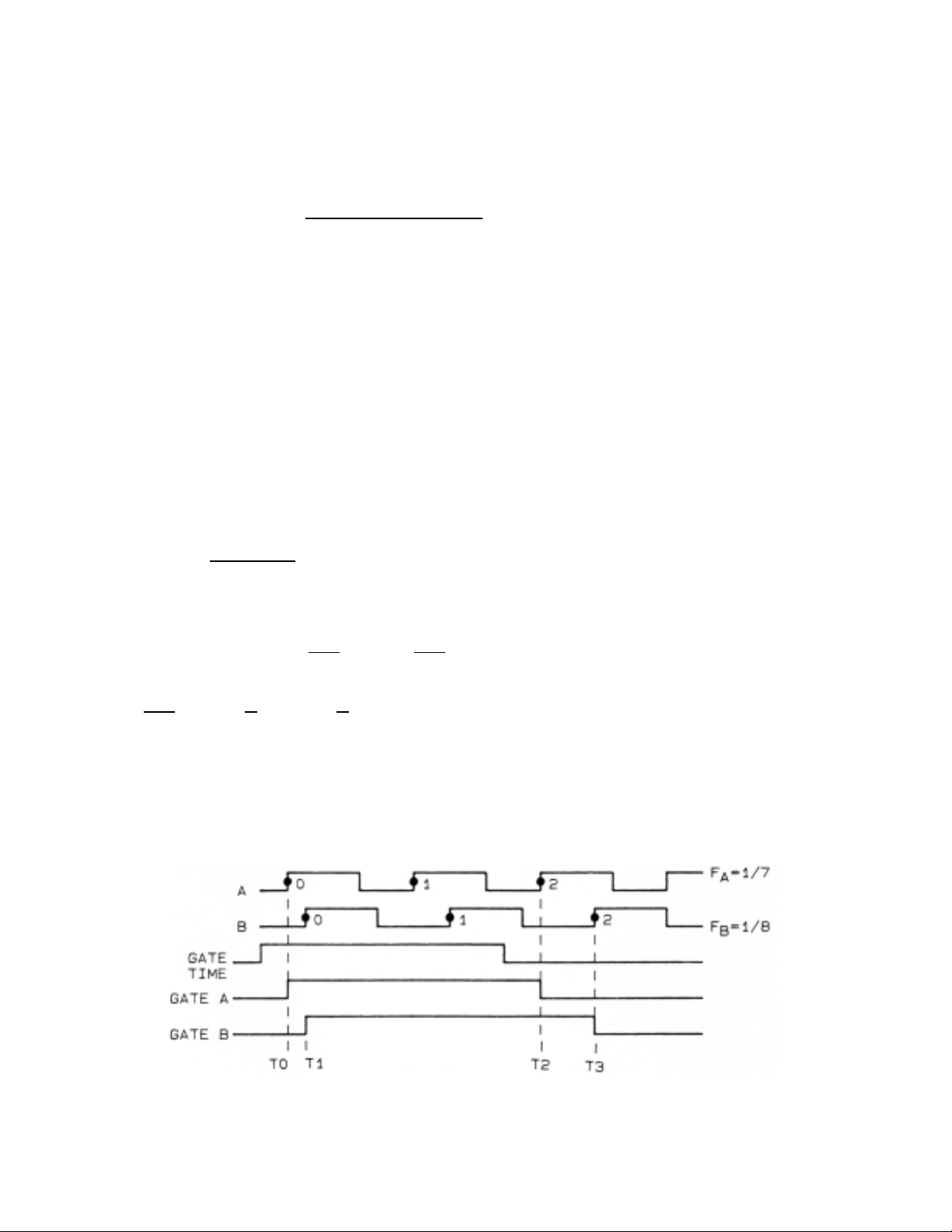
FREQUENCY RATIO
When the B input frequency is greater than 5 kHz, frequency ratio measurement is done
similar to the frequency measurement, except that the B counter counts the B input pulses,
instead of internal clock pulses. The display resolution is determined by the B input
frequency and the averaging gate time (Auto-range, Scale = 1).
Display Resolution =
1
F
B
. (Averaging Time)
Where: Averaging Time = Nominal Gate Time + 2.5 ms + time to
complete the last A and B cycles.
Gate Timing:
The measurement is started with the arming of the A flip-flop. The selected trigger slope of
the A input then sets the A flip-flop. This arms the B flip-flop and opens the A gate. Now
the selected trigger slope of the B input opens the B gate. At the conclusion of gate time,
the meter disarms the A flip-flop. Then the next A pulse closes the A gate and the next
B pulse closes the B gate. While the respective gates are open, the A and B input pulses
are counted by the A and B counters. The meter then reads the A and B counters and
calculates the frequency ratio.
Display = (
Counter B
) (Scale Factor) + OFFSET
Counter A
It should be noted that, because the scale factor and offset can be negative numbers, it is
possible to display K .
B-A
( or K .
A-B
) since
AA
K
.
B-A
= K (B- 1 ) =
B
.
K - K = Scale Factor = K
AAA
OFFSET = -K
When the B input frequency is less than 5 kHz, the meter interpolation method
achieves much greater accuracy than conventional counters. This feature makes the
meter very useful in low frequency ratio measurements.
Figure C-4 Frequency Ratio Measurement Timing
2-30
Page 68
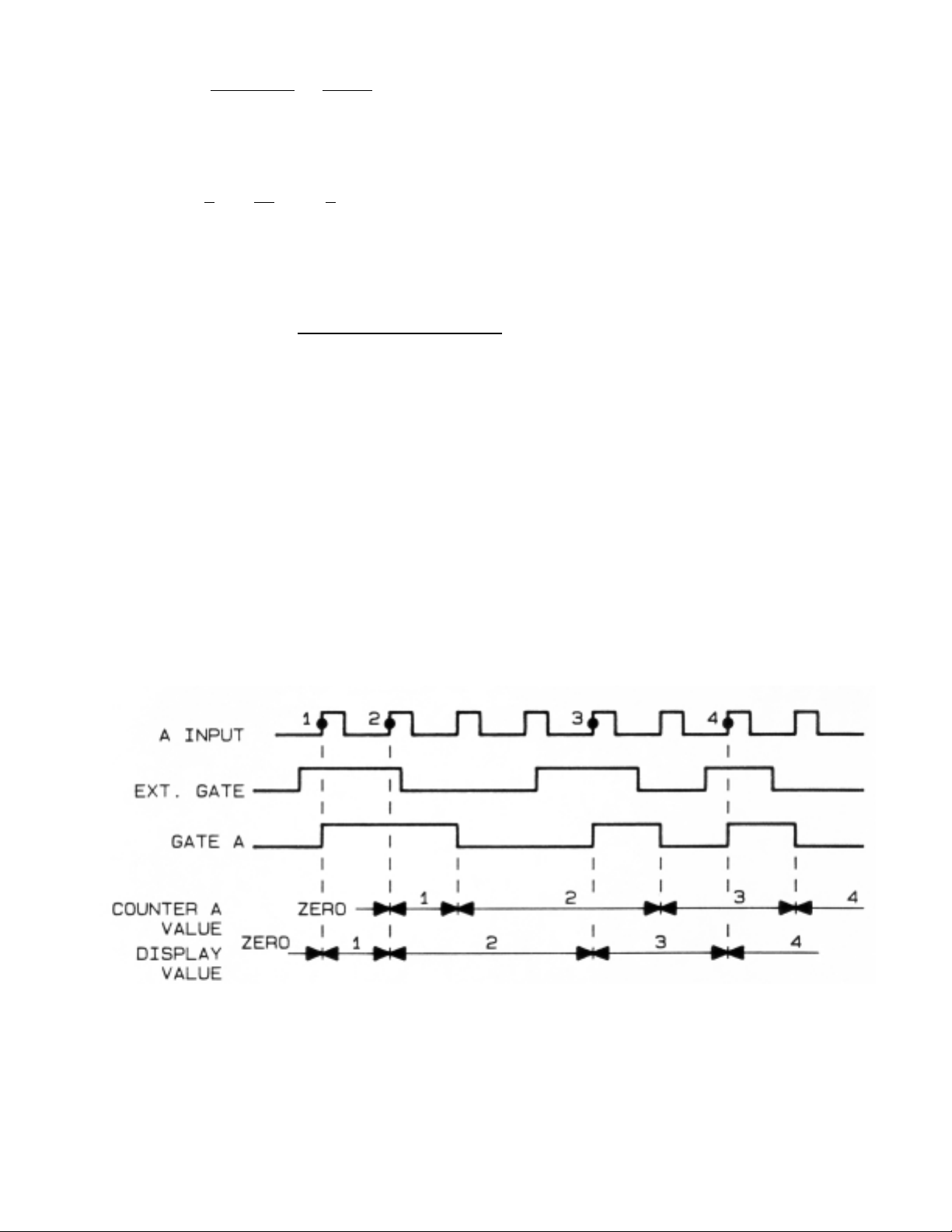
Display = (
Counter B
.
T2-T0
) (Scale Factor) + OFFSET
Counter A T3-T1
For the above waveforms and scale factor = 1, OFFSET = 0 :
Display =
2
.
14
=
7
2 16 8
When the B input frequency is less than 5 kHz, the display resolution is determined by the
Averaging Time only.
Display Resolution =
1
5000 . (Averaging Time)
The timer that records the T0, T1, T2 and T3 times has 160 seconds capacity, so when
measuring the ratio of very low frequencies, the total measurement time should not exceed
160 seconds.
TOTALIZE
Totalize is started by arming the A flip-flop. Then the first trigger slope of the A input sets the
A flip-flop and opens the Gate. This allows the A input pulses to be counted by the A counter.
The meter reads the A counter and adds one count to it if Gate A is open, so that the number
of A input pulses is displayed. This method of gating allows the input pulses to be repeatedly
gated by an external signal (on the external gate input) without any error.
Figure C-5 Timing in Totalize Function
2-31
Page 69

It should be noted that the display value and the alarm outputs status lag the input pulses
by 0-25 milliseconds (calculation time) plus the communication time. This delay cannot be
seen on the display but when using the alarm outputs for control purposes, it may be
desired to reduce this delay as much as possible. This display update time is minimized by:
1. Disabling the parallel BCD data, if not used (sending data to the parallel BCD board
takes about 10 milliseconds);
2. Disabling the RS-232 output by leaving RTS open or false. (The RS-232 output
takes about 13 milliseconds at 9600 baud);
3. Using a multiplier scale factor (a divider scale factor lengthens the calculation time
about 10 sec).
With these provisions, the display update time is reduced to 8-15 milliseconds in totalize
and 20-30 milliseconds in other functions.
2-32
Page 70
APPENDIX D
GLOSSARY OF SYMBOLS AND TERMS
SYMBOL
DESCRIPTION OTHER POSSIBLE SETTINGS
AA ..SSCC
Scale Factor is a MULTIPLIER A/SC
Display = (measurement · scale) +
offset
AA//SSCC
Scale Factor is a DIVIDER A.SC
Display = (measurement/scale) +
offset
AA nnEEGG
A input trigger slope is NEGATIVE A POS
(counting negative edges)
AA PPOOSS
A input trigger slope is POSITIVE A nEG
(counting positive edges)
AAuuttoo
Auto-ranging is selected. F.F.F.F.F.F., fixed range with one of
The meter selects the decimal the six available decimal points
point.
bb nnEEGG
B input trigger slope is NEGATIVE b POS
(counting negative edges)
bb PPOOSS
B input trigger is POSITIVE b nEG
(counting positive edges)
CCAALLIIbb
CALIBRATION value, expressed in -99999 to 999999 ppm with six
parts per million possible decimal point positions
2-33
Page 71
SYMBOL DESCRIPTION OTHER POSSIBLE SETTINGS
CCnnFFGG 11
CONFIGURATION 1, set of six 6 digits, each can be 0 or 1 to
software switches, SS1-SS6 disable or enable a feature
CCnnFFGG 22
CONFIGURATION 2, set of six 6 digits, each can be 0 or 1 to
software switches, SS1-SS6 disable or enable a feature
FF..FF..FF..FF..FF..FF..
FIXED RANGE, with selected Auto, Auto-ranging
decimal point flashing
FFrr bb//aa
Meter function is FrEq, PEriod, ti Int, totAL
FREQUENCY RATIO B/A
(B input is divided by the A input)
ffrree99
Meter function is PEriod, ti Int, Fr b/A, totAL
FREQUENCY
(measures the A inputfrequency)
ffuunncc
Operating FUNCTION Available functions are:
Frequency, Period, Time Interval,
Frequency Ratio and Totalize
ggaattee tt
Nominal GATE TIME, the averaging The value ranges from 00.00 to
time that determines the display 99.99 seconds, with a fixed
update rate decimal point.
OOffffsseett
OFFSET (Preset) Ranges from -99999 to 390000 with
(Display = (Input X Scale) + Offset) a programmable decimal point
PPeerriioodd
Meter function is PERIOD FrEq, ti Int, Fr b/A, totAL
2-34
Page 72
SYMBOL DESCRIPTION OTHER POSSIBLE SETTINGS
rraannggee
RANGE Can be set to Auto-range (Auto)
or a fixed decimal point can be
selected (F.F.F.F.F.F.)
ssCCaallee
SCALE Factor Ranges from -99999 to 999999 with
a programmable decimal point.
Multiply or divide.
SSLLOOPPEE
Trigger SLOPE of the Input(s) Positive or negative slopes can be
selected for A and B inputs,
independently.
SSPP HHII
SETPOINT HIGH Ranges from -99999 to 999999 with
a programmable decimal point
SSPP LLOO
SETPOINT LOW Ranges from -99999 to 999999 with
a programmable decimal point
TTii IInntt
Meter function is TIME INTERVAL FrEq, PEriod, Fr b/A, totAL
A to B
ttoottAALL
Meter function is TOTALIZE FrEq, PEriod, ti Int, Fr b/A
2-35
Page 73
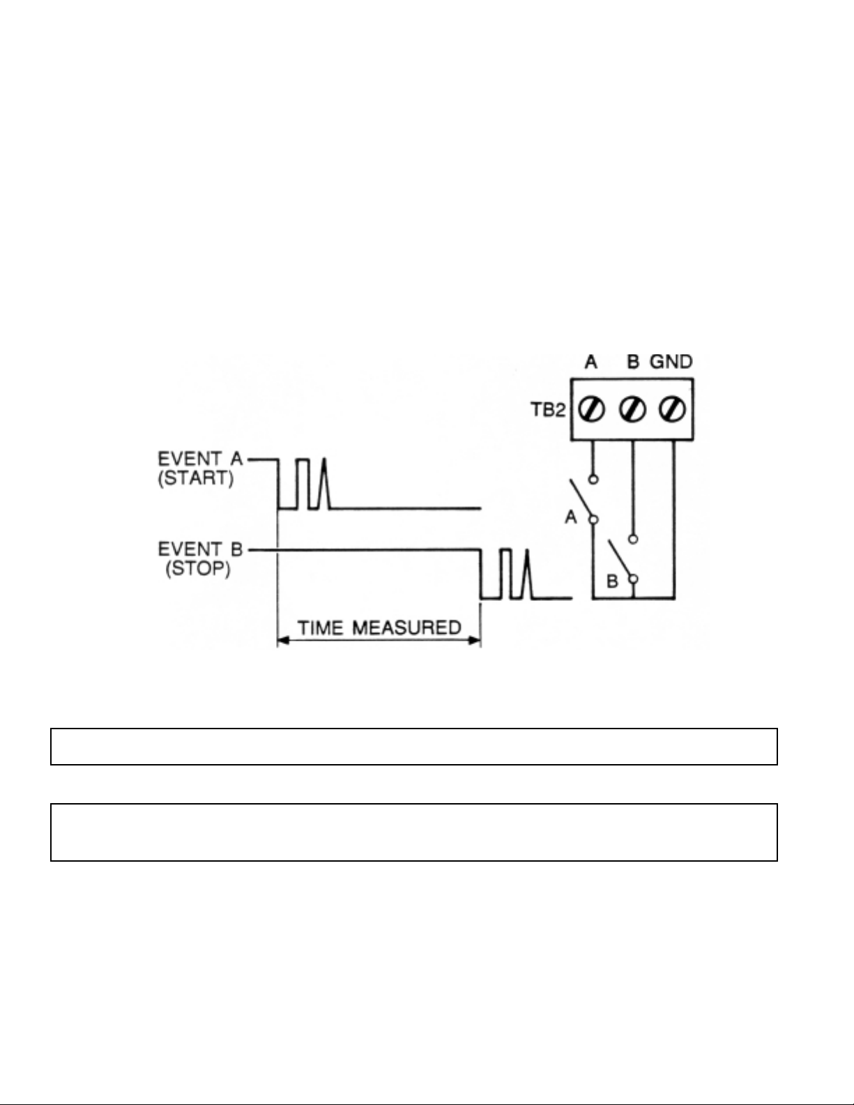
APPENDIX E
APPLICATION NOTES
Time-Interval Measurement
The Time-Interval Measurement is used to measure the time between events A and B and
display the measurement in seconds.
Features used: Function - set to time interval
Scale - use “divide by” 1000
Slope - negative A and B trigger slopes
Gate Time - set to 00.00 for single-event measurement
(no averaging)
Figure E-1 Time-Interval Measurement
2-36
NOTE: No reset is required; a new reading replaces the old reading automatically.
NOTE: Debouncing is not required; therefore, START and STOP pulses can be generated
with mechanical switches.
Page 74
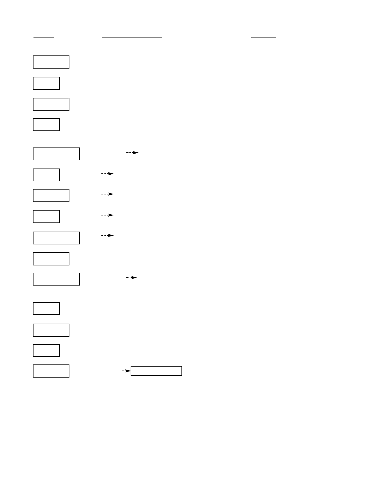
PUSH DISPLAY SHOWS NOTES
ENTER
ffuunncc
SET
ttii IInntt
Press until flashing ti Int is displayed.
ENTER
ssCCaallee
SET
aa//sscc
If A.SC is displayed, press SET to change it
to A/SC (divide by).
ADVANCE
11..0000000000 11..0000000000
Press until the decimal point is flashing.
SET
11000000..0000
Press until display reads 1000.00
ENTER
ssllOOppee
Press until SLOPE is displayed.
SET
aa nneegg
If A POS, press to toggle to A nEG.
ADVANCE
bb nneegg
If b POS, press SET to toggle to b nEG.
ENTER
ggaattee tt
Press until GAtE t is displayed.
ADVANCE
0000..3300 0000..3300
Press until 3 is flashing. (00.30 sec. is the
default Gate Time.)
SET
0000..0000
Press once.
ENTER
nnoossttoorr
Press until no Stor is displayed.
SET
ssttoorree
ENTER
ttii IInntt
measurement Display momentarily shows ti Int
(new function). If A and B input signals are
present, a time-interval measurement
replaces the A display.
2-37
`
`
`
`
`
`
`
`
`
`
`
`
`
`
`
`
`
`
`
`
`
`
`
`
`
`
`
`
`
`
Page 75
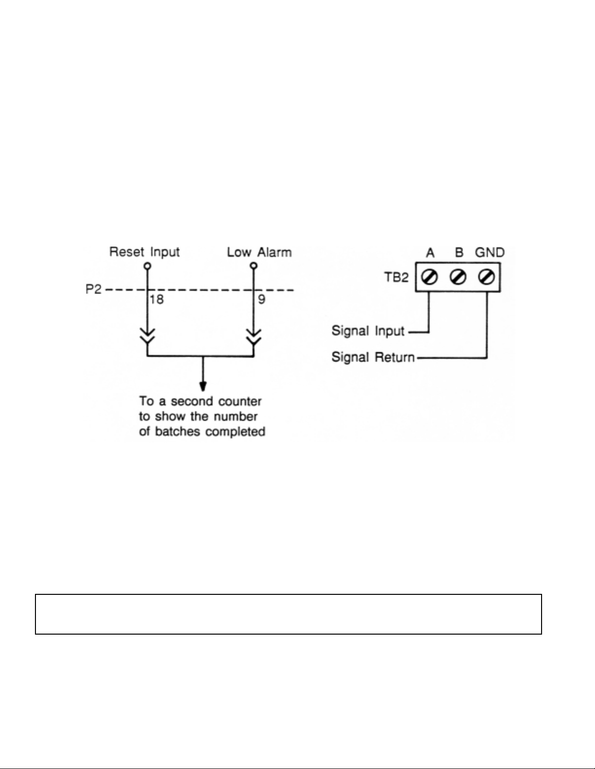
BATCH COUNTER
The Batch Counter is used to count repetitiously in descending order from 200 to 0. Each
five input pulses are counted as one count.
Features used: Function - set to TOTALIZE
Scale - set to “divide by” -5 (negative to count down)
Offset - set to 200 (starting point)
Setpoint Low - set to .01 so a zero
reading activates the Low Alarm
2-38
NOTE: Input pulses must be TTL compatible. If they are generated by a mechanical switch,
a signal conditioner option should be used for debounding.
Page 76
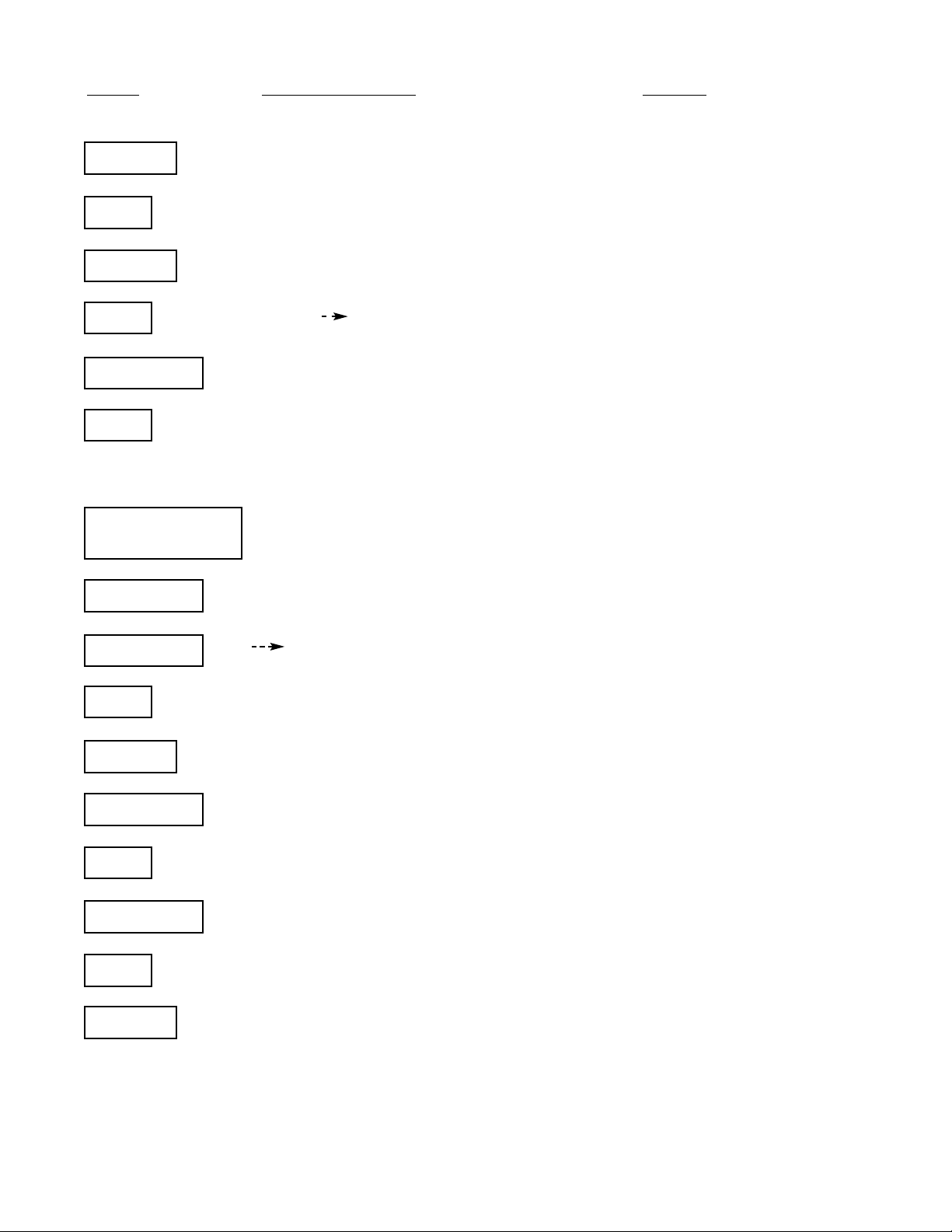
PUSH DISPLAY SHOWS NOTES
ENTER
ffuunncc
SET
ttoottaall
Press until totAL is flashing.
ENTER
SSCCAALLEE
SET
aa ..ssCC aa//ssCC
If A.SC, press again to get A/SC.
ADVANCE
11..0000000000
SET
--..0000000000
Press until a negative sign is displayed.
(Only the leftmost digit can be set to a
negative sign.)
ADVANCE and
--55..00000000
Use ADVANCE and SET to set the
SET scale factor value to -5.0000.
ENTER
OOFFFFSSEETT
ADVANCE
000000000000..
Press until digit #3 is flashing.
SET
000000220000..
Press to make digit #3 a 2.
ENTER
SSPP LLOO
Press until Setpoint Low is displayed.
ADVANCE
000000000000..
Press ADVANCE until digit #4 is flashing.
SET
000011000000..
Press once.
ADVANCE
000011000000..
Press until the decimal point is flashing.
SET
00..00110000OO
Press once.
ENTER
NNooSSTToorr
Press until no Stor is displayed.
Use SET and ENTER to store the new program in nonvolatile memory.
2-39
`
`
`
`
`
`
`
`
`
`
`
`
`
`
`
`
`
`
`
`
`
`
`
`
`
`
`
`
`
`
`
`
`
`
Page 77
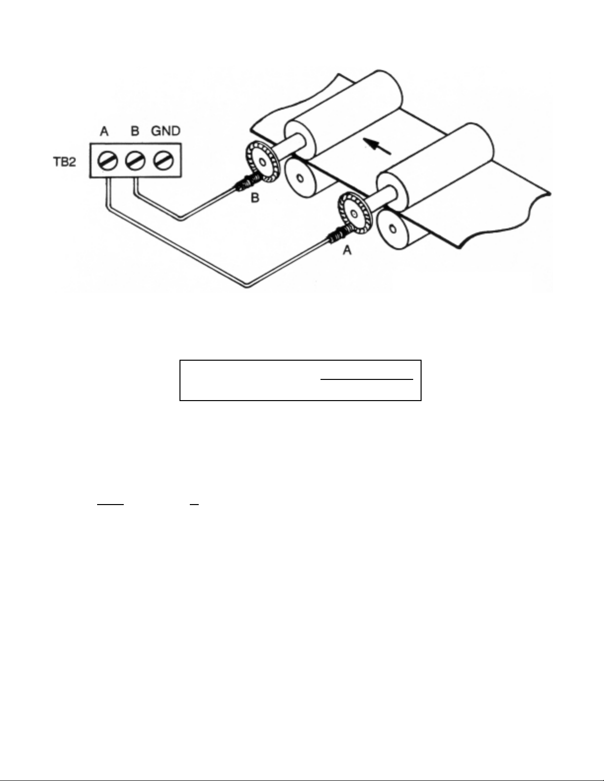
FREQUENCY RATIO
In some applications it is necessary to measure the ratio or draw between two frequencies.
For ratio measurement, just program the Function to Fr b/A (frequency ratio B input/A input).
To measure the draw in a percentage, use the frequency ratio mode. Set the Scale Factor to
“multiply by 100” and set the Offset to “ -100” .
Draw % =
B - A
X 100 =
B
.
100 - 100
AA
Features used: Function - set to Fr b/A
Scale - set to “multiply by 100”
Offset - set to “ -100”
2-40
NOTE: Display shows
B input frequency
A input frequency
Page 78
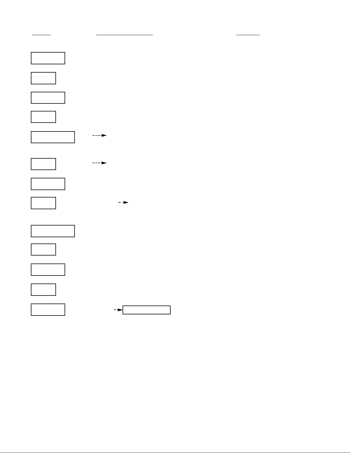
PUSH DISPLAY SHOWS NOTES
ENTER
ffuunncc
SET
ffrr bb//aa
Press until Fr b/A is flashing.
ENTER
SSCCAALLEE
SET
AA ..SSCC
If A/SC, press again to get A.SC.
ADVANCE
11..0000000000
This is the default scale factor value. Press until
the decimal point is flashing.
SET
110000..000000
Set the decimal point in the position shown.
ENTER
OOFFFFSSEETT
SET
000000000000 --0000000000..
This is the default value of OFFSET. Press until
the minus sign is flashing
.
ADVANCE
--0000000000..
Press until digit #3 is flashing.
SET
--0000110000..
Press once.
ENTER
nnooSSttoorr
Press until no Stor is flashing.
SET
SSttoorrEE
ENTER
FFrr bb//aa
measurement
Display shows the new function momentarily.
A measurement replaces this display.
2-41
`
`
`
`
`
`
`
`
`
`
`
`
`
`
`
`
`
`
`
`
`
`
`
`
`
`
Page 79
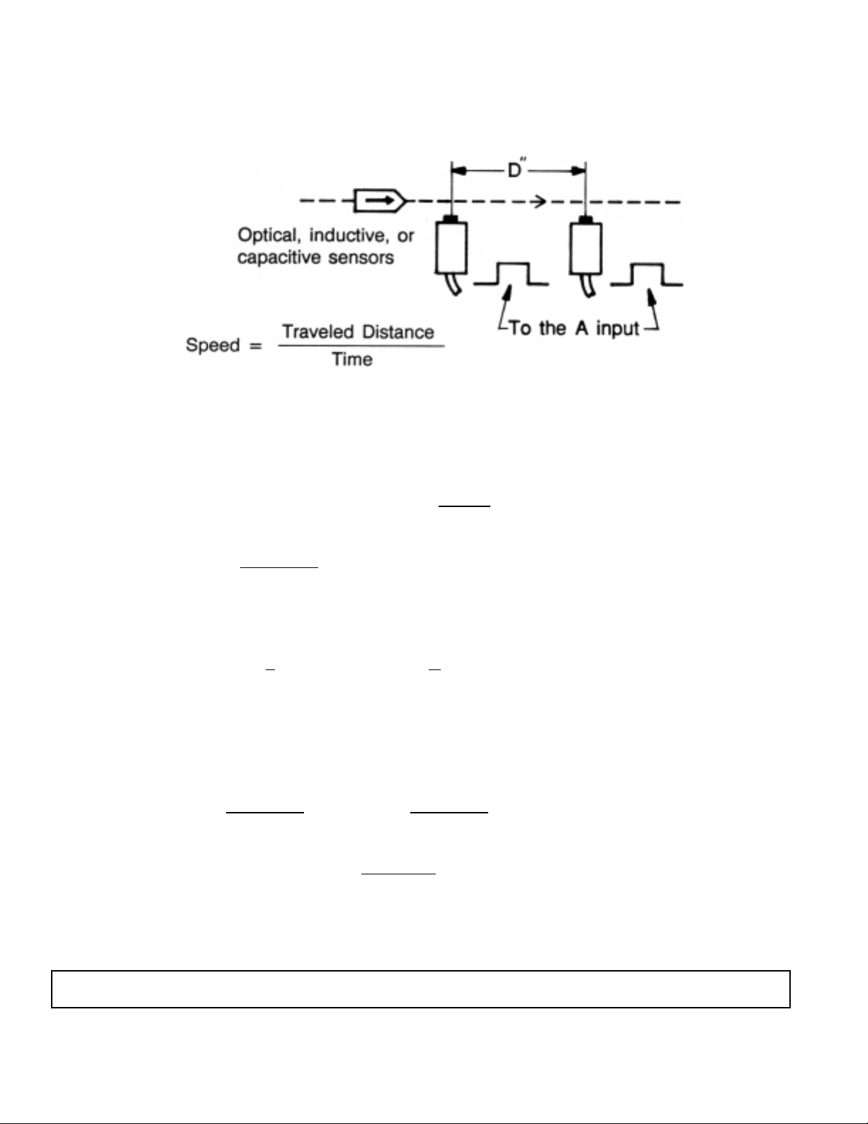
SINGLE-EVENT SPEED MEASUREMENT
In some applications it is necessary to measure the speed of a moving object and to
display the speed in miles per hour (mi/hr).
Place two sensors or switches, D inches apart. Use Frequency mode and select zero
Gate Time. (The meter will use 2.5 - 3.0 millisecond gate time.)
To find the speed in inches per second (in/sec):
Display = Scale Factor x Frequency (Hz) =
1
X Scale Factor
T (sec)
Speed (in/sec) =
D (inches)
T (sec)
To display the speed:
Display = Speed =>
1
X Scale Factor =
D
TT
Scale Factor (for in/sec) = D (inches) ; “multiply”
To find the speed in mi/hr:
Scale Factor =
D (inches)
X 3600 =
D (inches)
; “multiply by”
63360 17.6
OR
17.6
; “divide by”
D (inches)
2-42
NOTE: The time between pulse A and B must be longer than 3 milliseconds.
Page 80
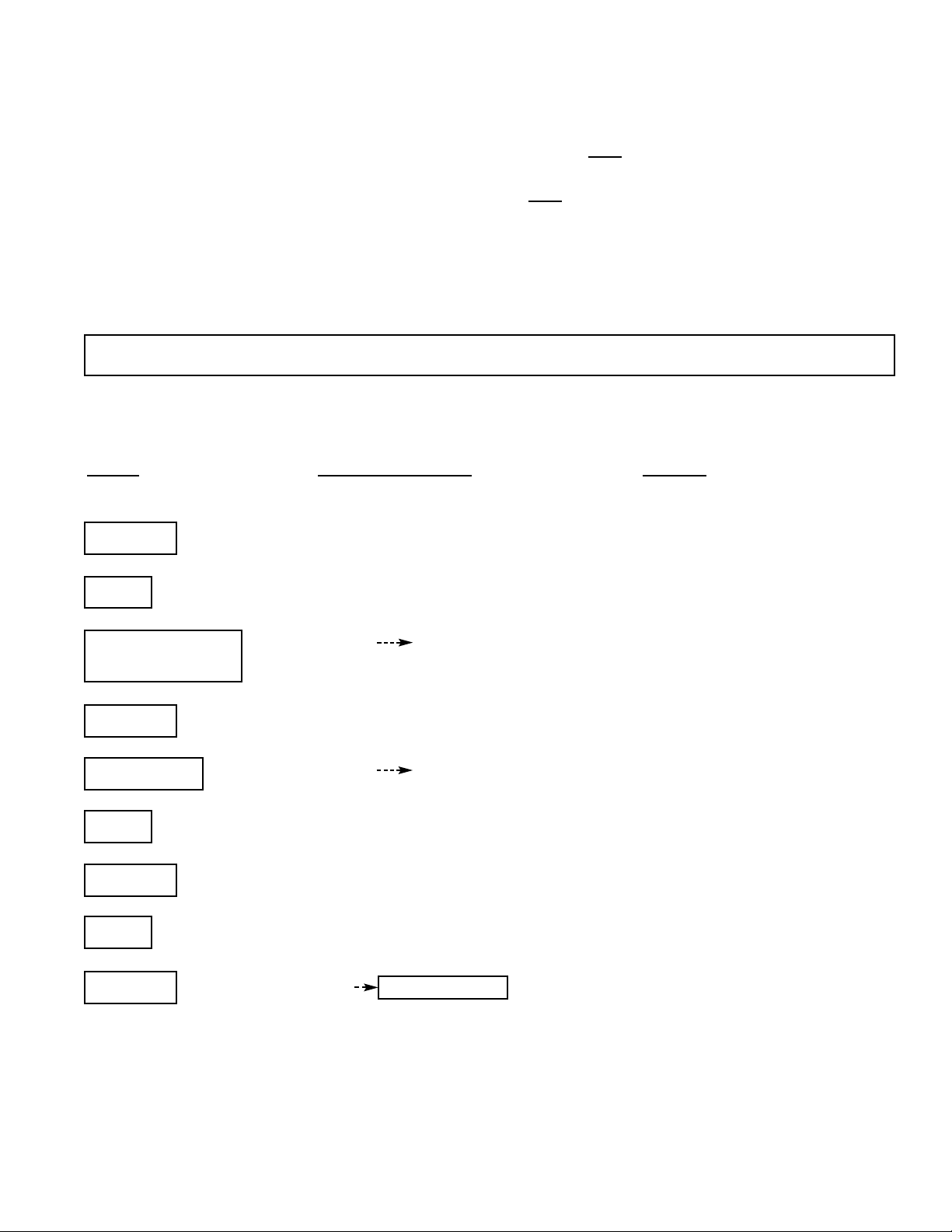
If D = 4” :
Features used: Function - set to Frequency mode
Scale Factor - set to “multiply by” D= .22727 or
17.6
“divide by”
17.6
= 4.4
D
Gate Time - set to 00.00 (The meter will use
2.5 - 3.0 millisecond gate time.)
PUSH
DISPLA
Y SHOWS NOTES
ENTER
SSCCAALLEE
Press until SCALE is displayed.
SET
AA//SSCC
Press until A/SC is selected.
ADVANCE and
11..0000000000 44..4400000000
Use ADVANCE and SET pushbuttons to
SET program the scale value to 4.4.
ENTER
GGAATTEE TT
Push until GAtE t is displayed.
ADVANCE
0000..3300 0000..3300
This is the default Gate Time.
SET
0000..0000
Press once for zero.
ENTER
nnooSSttoorr
Press until no Stor is displayed.
SET
SSttoorrEE
ENTER
FFrrEE99
measurement Display shows FrEq until a measurement
is done.
2-43
NOTE: Reset the meter by pushing the three center pushbuttons prior to each measurement.
`
`
`
`
`
`
`
`
`
`
`
`
`
`
`
`
`
`
`
`
`
`
`
`
`
`
`
`
Page 81
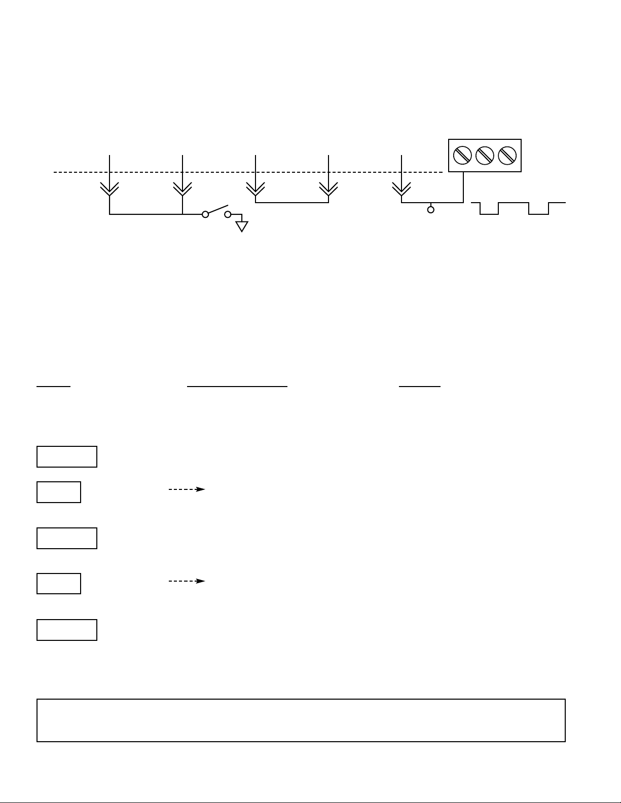
HIGH SPEED MEASUREMENTS
The previous example requires a time of more than 3 milliseconds between two pulses.
This limits the maximum measureable speed to 18.9394 D or 75.7576 mi/hr when D = 4”.
For faster speed measurements, use the following circuit:
SPARE FF SPARE FF EXT GATE SPARE FF A B GND
RESET RESET IN Q OUT IN CLK IN
P2
2 18 4 19 5
External Pulses from transducers
Reset switch
1. Select the scale factor as described in the previous example.
2. Select the negative trigger slope for the A input.
3. Disable the internal gate by setting the software switch SSW #6 of
Configuration 1.
4. Reset the meter prior to each measurement by an external switch or pulse
connected to pin 2 and pin 18 of P2.
PUSH
DISPLAY SHOWS NOTES
Select the scale factor as shown in the previous example.
ENTER
SSLLOOPPEE
Press until SLOPE is displayed.
SET
AA nnEEGG
Set the trigger slope to A negative.
ENTER
CCNNFFGG 11
Press until CnFG 1 (Configuration 1) is
displayed.
SET
110000000000
Set SSW #6 to 1 (leftmost digit).
ENTER
NNooSSttoorr
Press until no Stor is displayed. Use SET
and ENTER to save the changes in the
nonvolatile memory as shown in the
previous example.
2-44
NOTE: If your tranducers generate positive true pulses, use the spare inverter to convert them
to negative true pulses.
`
`
`
`
`
`
`
`
TB2
Page 82
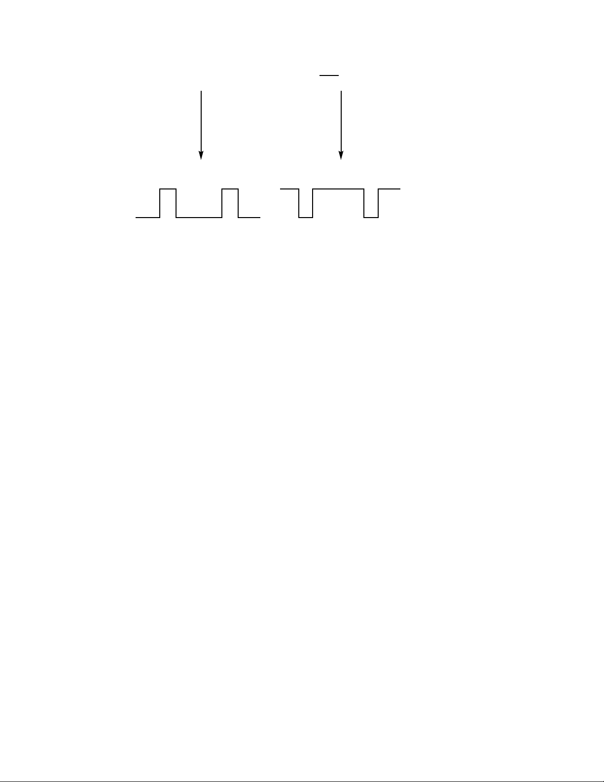
BUF IN BUF OUT
- - - - - - - - - - - - - - - - - - - - - - - - - - - - - - - - - - - - - P2
14 15
High = +5 V
Low = 0
Positive True Pulses Negative True Pulses
With this circuit, very high speed measurements are possible. The only limitation is that the
two pulses should not overlap.
To measure the speed of a bullet in mi/hr:
1. Place two optical sensors 10” apart.
2. Use the above circuit and install the SA-F push-on jumper on the main board for better
accuracy.
3. Select the Scale Factor as described in the previous example. (Scale Factor
“multiplier” = .56818 or Scale Factor “divider” = 1.76) The turn on and turn off delays
of the optical sensors determine the maximum measureable speed. For example,
if the sensor can generate a pulse as short as 5 µs and the bullet is 1” long, the maximum
speed is 11363 mi/hr.
2-45
Page 83

READING ZERO WHEN THERE IS NO INPUT
If the meter input is disconnected during a measurement, the last reading remains on the
display permanently. Although this is a requirement in very low frequency measurements,
it is undesireable in some applications.
To make the meter read zero in frequency mode when the input is disconnected, use a
signal conditioner option (P6A1A/DPFX300, P6A2A/DPFX400, or P6A3/DPFX200) to reset
the meter.
The default setting of P6A1A
/DPFX300
provides a low true signal on pin 2 of TB2
(B input) when the input frequency is less than 9 Hz.
This signal can be used to reset the
meter by connecting it to pin 18 of P2, the RESET input. On the P6A3/DPFX200, a similar
signal is generated on pin 4 of TB3 when the input frequency is less than 0.7 Hz. The
RS-232, however, is not updated; and alarm outputs will be in the no-alarm state (open
collector).
A new feature is provided in the new version of the meter’s microcomputer (part #49943-03
which is printed on the 40 pin chip) to read zero when input pulses are missing for more
than about 2 seconds (1.92 to 2.56 seconds). To enable this feature, software switch
SSW #4 of Configuration 1 must be set as follows: CnFG 1 = XX1XXX. If the Gate Time is
more than 2.56 seconds, the meter will wait longer.
The alarm outputs, RS-232, parallel BCD, and analog outputs, are updated like a true zero
measurement.
Time with no input to read zero (in seconds)
Gate Time (in seconds) (CnFG 1 = XX1XXX, U5 = 49943-03
0 TO 2.55 1.92 TO 2.56
2.56 TO 5.11 2.56 + (1.92 TO 2.56)
5.12 TO 7.67 5.12 + (1.92 TO 2.56)
Table E-1 Time with No Input to Read Zero
2-46
Page 84
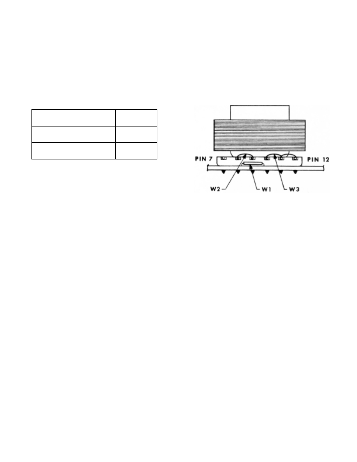
APPENDIX F
POWER OUTPUT/INPUT
The meter comes with AC power as standard (115 V ac or 230 V ac). A DC power
supply board is available as an option. Refer to Figure 3-1 for location of rear pins.
F.1 CHANGING VOLTAGE OPERATION
Operation Install Remove
115 V W2, W3 W1*
230V W1* W2, W3
* Insulated wire recommended.
AC Power Supply
In the AC powered units, pin 11 of P2 is an unregulated voltage, 5.5 to 9 V and pin 8
of P2 is a +5 V regulated voltage. In nontotalize functions, a total of 50 mA can be drawn
from these outputs to drive external circuitry. In totalize function, 20 mA can be drawn if
normal or dim display brightness has been selected.
Alternatively, pin 11 can be used as a power input for backup battery connection. Connect
the backup battery to this pin with a diode as shown in Figure F-1. The backup battery
should be capable of supplying 60 mA at 6 to 12 V. When the AC power is disconnected,
the display turns off. If the external battery can supply 400 mA, display blanking may be
prevented by connecting the BLANK ENABLE, pin 16 of P2, to ground. In this case, if the
battery voltage is higher than 9 V, the maximum display brightness must not be used.
2-47
Figure F-1 Side View of Transformer
Page 85
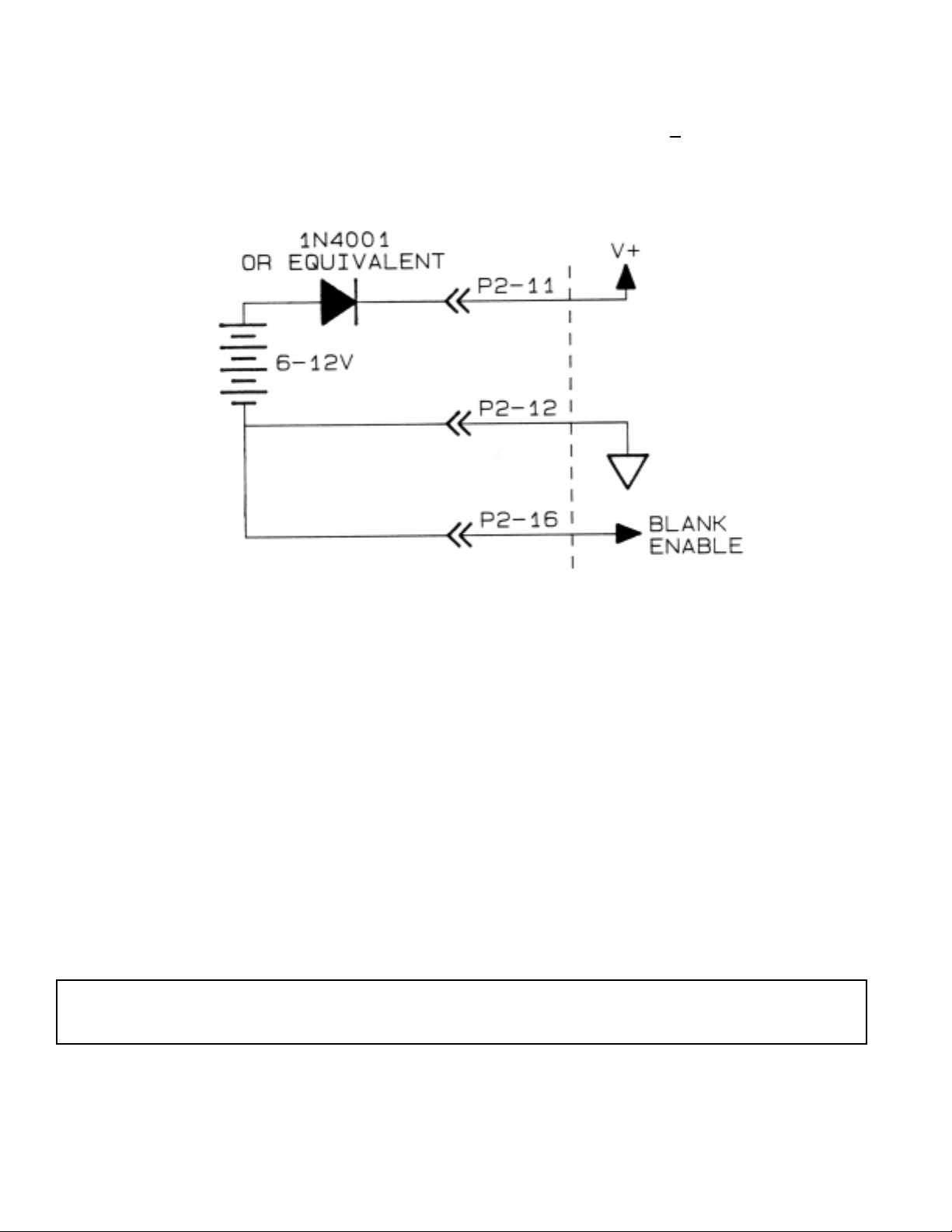
The backup battery does not drive the isolated signal conditioner circuitry.
In the absence of AC power, the meter can be powered with a 5 V
+
5% regulated voltage.
Connect the external +5 V to pins 8 and 12 (+5 V and V+) of the P2 connector.
Figure F-2 Connection of an External Battery
DC Power Supply Option
The power transformer is replaced with a DC to DC converter, which allows operation
with a single DC power source.
Refer to Figure 3-1 for rear pin assignments. Connect a 9.5 to 32 V dc power source
capable of supplying 1 A current to TB1-pins 2 (positive) and 3 (negative). The outputs
of the DC power supply board power the entire unit.
2-48
NOTE: The maximum display brightness must not be used (Configuration 2 must be XXXX1)
with a signal conditioner or an upper-board option.
Page 86

NOTES
2-49
Page 87

WARRANTY/DISCLAIMER
OMEGA ENGINEERING, INC. warrants this unit to be free of defects in materials and workmanship for a
period of 13 months from date of purchase. OMEGA’s WARRANTY adds an additional one (1) month grace
period to the normal one (1) year product warranty to cover handling and shipping time. This ensures
that OMEGA’s customers receive maximum coverage on each product.
If the unit malfunctions, it must be returned to the factory for evaluation. OMEGA’s Customer Service
Department will issue an Authorized Return (AR) number immediately upon phone or written request.
Upon examination by OMEGA, if the unit is found to be defective, it will be repaired or replaced at no
charge. OMEGA’s WARRANTY does not apply to defects resulting from any action of the purchaser,
including but not limited to mishandling, improper interfacing, operation outside of design limits,
improper repair, or unauthorized modification. This WARRANTY is VOID if the unit shows evidence of
having been tampered with or shows evidence of having been damaged as a result of excessive corrosion;
or current, heat, moisture or vibration; improper specification; misapplication; misuse or other operating
conditions outside of OMEGA’s control. Components in which wear is not warranted, include but are not
limited to contact points, fuses, and triacs.
OMEGA is pleased to offer suggestions on the use of its various products. However,
OMEGA neither assumes responsibility for any omissions or errors nor assumes liability for
any damages that result from the use of its products in accordance with information provided
by OMEGA, either verbal or written. OMEGA warrants only that the parts manufactured by the
company will be as specified and free of defects. OMEGA MAKES NO OTHER WARRANTIES OR
REPRESENTATIONS OF ANY KIND WHATSOEVER, EXPRESSED OR IMPLIED, EXCEPT THAT OF
TITLE, AND ALL IMPLIED WARRANTIES INCLUDING ANY WARRANTY OF MERCHANTABILITY
AND FITNESS FOR A PARTICULAR PURPOSE ARE HEREBY DISCLAIMED. LIMITATION OF
LIABILITY: The remedies of purchaser set forth herein are exclusive, and the total liability of
OMEGA with respect to this order, whether based on contract, warranty, negligence,
indemnification, strict liability or otherwise, shall not exceed the purchase price of the
component upon which liability is based. In no event shall OMEGA be liable for
consequential, incidental or special damages.
CONDITIONS: Equipment sold by OMEGA is not intended to be used, nor shall it be used: (1) as a “Basic
Component” under 10 CFR 21 (NRC), used in or with any nuclear installation or activity; or (2) in medical
applications or used on humans. Should any Product(s) be used in or with any nuclear installation or
activity, medical application, used on humans, or misused in any way, OMEGA assumes no responsibility
as set forth in our basic WARRANTY/DISCLAIMER language, and, additionally, purchaser will indemnify
OMEGA and hold OMEGA harmless from any liability or damage whatsoever arising out of the use of the
Product(s) in such a manner.
RETURN REQUESTS/INQUIRIES
Direct all warranty and repair requests/inquiries to the OMEGA Customer Service Department. BEFORE
RETURNING ANY PRODUCT(S) TO OMEGA, PURCHASER MUST OBTAIN AN AUTHORIZED RETURN (AR)
NUMBER FROM OMEGA’S CUSTOMER SERVICE DEPARTMENT (IN ORDER TO AVOID PROCESSING
DELAYS). The assigned AR number should then be marked on the outside of the return package and on any
correspondence.
The purchaser is responsible for shipping charges, freight, insurance and proper packaging to prevent
breakage in transit.
FOR WARRANTY RETURNS, please have the
following information available BEFORE contacting
OMEGA:
1. Purchase Order number under which the product
was PURCHASED,
2. Model and serial number of the product under
warranty, and
3. Repair instructions and/or specific problems
relative to the product.
OMEGA’s policy is to make running changes, not model changes, whenever an improvement is possible. This affords our
customers the latest in technology and engineering.
OMEGA is a registered trademark of OMEGA ENGINEERING, INC.
© Copyright 2017 OMEGA ENGINEERING, INC. All rights reserved. This document may not be copied, photocopied,
reproduced, translated, or reduced to any electronic medium or machine-readable form, in whole or in part, without the prior
written consent of OMEGA ENGINEERING, INC.
FOR NON-WARRANTY REPAIRS, consult
OMEGA for current repair charges. Have
the following information available BEFORE
contacting OMEGA:
1. Purchase Order number to cover the COST
of the repair,
2. Model and serial number of the product, and
3. Repair instructions and/or specific problems
relative to the product.
Page 88

Where Do I Find Everything I Need for
Process Measurement and Control?
OMEGA…Of Course!
Shop online at omega.com
TEMPERATURE
MU
Thermocouple, RTD & Thermistor Probes, Connectors,
Panels & Assemblies
MU
Wire: Thermocouple, RTD & Thermistor
MU
Calibrators & Ice Point References
MU
Recorders, Controllers & Process Monitors
MU
Infrared Pyrometers
PRESSURE, STRAIN AND FORCE
MU
Transducers & Strain Gages
MU
Load Cells & Pressure Gages
MU
Displacement Transducers
MU
Instrumentation & Accessories
FLOW/LEVEL
MU
Rotameters, Gas Mass Flowmeters & Flow Computers
MU
Air Velocity Indicators
MU
Turbine/Paddlewheel Systems
MU
Totalizers & Batch Controllers
SM
pH/CONDUCTIVITY
MU
pH Electrodes, Testers & Accessories
MU
Benchtop/Laboratory Meters
MU
Controllers, Calibrators, Simulators & Pumps
MU
Industrial pH & Conductivity Equipment
DATA ACQUISITION
MU
Communications-Based Acquisition Systems
MU
Data Logging Systems
MU
Wireless Sensors, Transmitters, & Receivers
MU
Signal Conditioners
MU
Data Acquisition Software
HEATERS
MU
Heating Cable
MU
Cartridge & Strip Heaters
MU
Immersion & Band Heaters
MU
Flexible Heaters
MU
Laboratory Heaters
ENVIRONMENTAL
MONITORING AND CONTROL
MU
Metering & Control Instrumentation
MU
Refractometers
MU
Pumps & Tubing
MU
Air, Soil & Water Monitors
MU
Industrial Water & Wastewater Treatment
MU
pH, Conductivity & Dissolved Oxygen Instruments
M0911/0717
 Loading...