

Page 1
User’s Guide
Shop online at
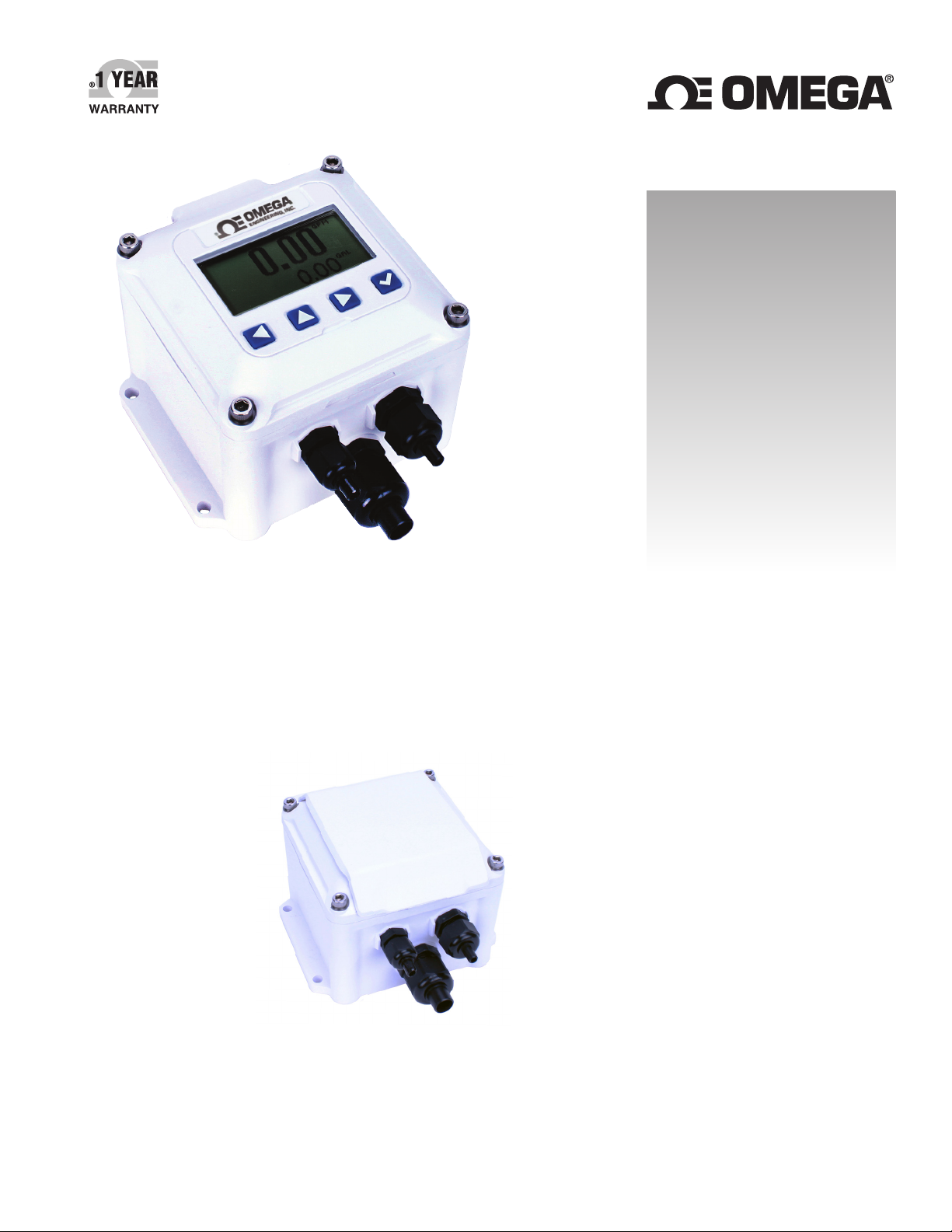
DPF143W - wall mounted
DPF144W - wall mounted
DPF143P - panel mounted
DPF144P - panel mounted
With optional cover
omega.com
e-mail: [email protected]
For latest product manuals:
www.omegamanual.info
SM
DPF143/144
Rate/Total Indicator
Page 2

omega.com [email protected]
Servicing North America:
U.S.A. Omega Engineering, Inc.
Headquarters: Toll-Free: 1-800-826-6342 (USA & Canada only)
Customer Service: 1-800-622-2378 (USA & Canada only)
Engineering Service: 1-800-872-9436 (USA & Canada only)
Tel: (203) 359-1660 Fax: (203) 359-7700
e-mail: [email protected]
For Other Locations Visit omega.com/worldwide
The information contained in this document is believed to be correct, but OMEGA accepts no liability for any errors it contains, and reserves
the right to alter specifications without notice.
Page 3

TABLE OF CONTENTS
General Information
General Information ...............................................................................................................................................................Page 4
Specications ............................................................................................................................................................................Page 4
Features .......................................................................................................................................................................................Page 5
Options ........................................................................................................................................................................................Page 4
Accessories ................................................................................................................................................................................Page 5
Pulse Output Function Table ...............................................................................................................................................Page 6
Installation
Wall Mount ................................................................................................................................................................................Page 7
Meter Mount .............................................................................................................................................................................Page 7
Panel Mount ..............................................................................................................................................................................Page 7
Connections
Connections for DPF143/3-Wire Mechanical Meter ..................................................................................................Page 8
Connections for DPF143-DPS/DPF144-DPS—115Vac Option ...............................................................................Page 9
Connections for DPF144/3-Wire Mechanical/Dual Scaled Pulse Out .................................................................Page 9
Connections for DPF144/FMG900/980 Series .............................................................................................................Page 10
Connections for DPF144-DPS/FMG900/980 Series ...................................................................................................Page 10
Settings
K-Factor .......................................................................................................................................................................................Page 11
Changing Flow Indicator Settings .....................................................................................................................................Page 11
Menu Navigation ...................................................................................................................................................................Page 11
The DPF144 Secondary Menu Functions ....................................................................................................................... Page 13
DPF143/144 SERIES INSTRUCTIONS
Troubleshooting
Problem, Probable Causes, Things to Try.......................................................................................................................Page 14
Page 3 omega.com
Page 4
GENERAL INFORMATION
DPF143/144 SERIES INSTRUCTIONS
The DPF143/144 ow computers are microcontrollerbased indicator/transmitters that interface with pulse
output ow sensors to compute and display ow rate, ow
total, and also generate output signals representing ow.
The DPF143 has one scaled pulse output and one pulse
pass through. The DPF144 has two scaled pulse outputs.
Galvanic isolation is provided for most pulse outputs.
The DPF143 may be powered by an external DC power
source or an optional internal AC power supply*. The
DPF144 is a “two-wire” or “loop powered” device, meaning
that it is powered by the 4-20 mA loop circuit itself. An
optional internal AC power supply* is available for the
DPF144 with dual 24 and 12VDC outputs to power both
the loop and sensors requiring more power than the loop
can supply.
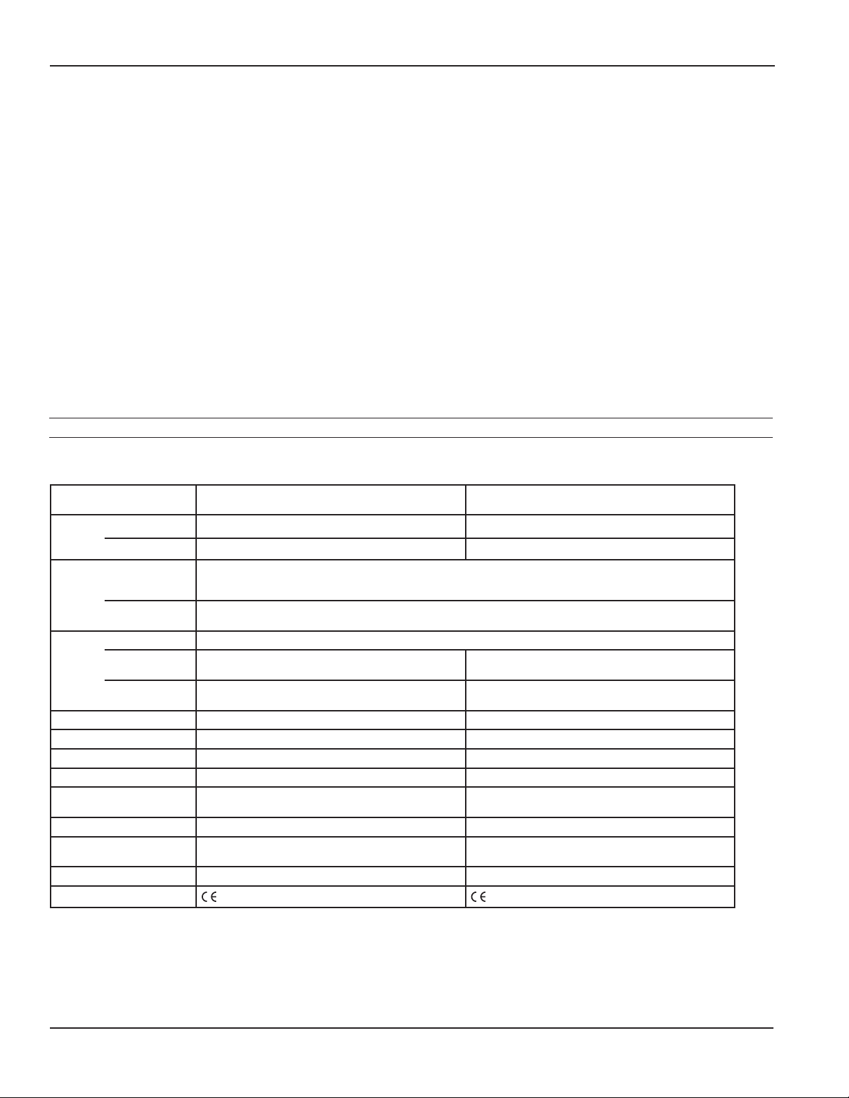
Specications*
DPF143 Series DPF144 Series
Power
7-30Vdc, 4mA 7-30Vdc, 4mA (4-20 mA when loop-powered)
Pulse and 4-20mA analog outputs can be used to signal
external devices, e.g. certain metering pumps and water
treatment controls. Alternatively, one or more pulse
outputs can be congured as alarm outputs. These ow
computers can be password protected to prevent resetting
the total or changing conguration settings.
The DPF143/144 meters are available in wall and meter
mount congurations, and can also be panel mounted.
Some congurations can be converted from wall to meter
or meter to wall after installation if needed. Consult Omega
for details.
Order the DPF144 only if a 4-20mA output signal is
a requirement. Otherwise the DPF143 offers the most
exibility.
*Internal power supply is available for the wall mount option only.
Display
Units Rate Units
Outputs Pulse Output 1 Scaled pulse output, high alarm output or low alarm output - optoisolated
Set P Range 0.1 - 99999.9 units/pulse 0.1 - 99999.9 units/pulse
Input 5V pulse or contact closure 5V pulse or contact closure
Input Range 0.75
K-Factor Range .001 - 999999.999 .001 - 999999.999
Flow Alarm Output
Range
Operating Temperature 0˚ to 55˚ C (-32˚ to 131˚ F) 0˚ to 55˚ C (-32˚ to 131˚ F)
Non-Operating
Temperature
Environmental NEMA 4X, IP67 NEMA 4X, IP67
Regulatory
Rate 5-digit autorange 5-digit autorange
Total 8-digit 8-digit
Gallons/Second/Minute/Hour/Day, Liter/Second/Minute/Hour/Day, Cubic Feet/Second/Minute/Hour/Day, Cubic
Meters/Second/Minute/Hour/Day, Miner’s Inch, Mega Liters/Day, Million Gallons/Day, Fluid Oz/Second/Minute/
Hour/Day, Barrels(42 gal)/ Second/Minute/Hour/Day
Total Units
Pulse Output 2 Pulse pass through
Loop Power
Output
Gallon, Gallon x 1000, Liters, Mega Liter, Cubic Meter, Acre Feet, Cubic Feet,
Cubic Feet x 1000, Million Gallon, Miner’s Inch Day, Acre Inch, Fluid Ounce, Barrels(42 gal)
Scaled pulse output, high alarm output or low alarm
1
output
N/A 4-20mA Loop
2
- 2000Hz 0.752 - 2000Hz
0.1 - 99999.9 0.1 - 99999.9
-40˚ to 75˚ C (-40˚ to 158˚ F) -40˚ to 75˚ C (-40˚ to 158˚ F)
Mark Mark
1
* Specications subject to change. Please consult our website for current data (omega.com).
1 Scaled output pulses have a xed width of 100ms. Maximum pulses per second is 6.5Hz
2 For pulse frequencies <1 Hz, increase setting in SET F menu to 3 or higher.
Page 4 omega.com
Page 5
Features
DPF143/144 SERIES INSTRUCTIONS
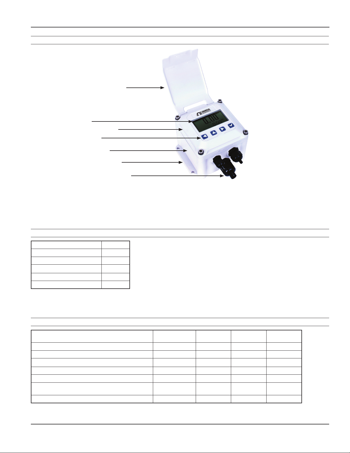
Hinged Display Cover
(Optional - DPF140-HC)
Display
Electronics Module
Setup Keys*
Lower Housing
Wall-Mount Brackets
Cable Gland Strain Relief
* Includes password protection for tamper prevention when needed
Options
Description Option #
Tamper-evident kit, wire seal TE
Non-resettable total NR
Hinged display cover HC
Built-in dual power supply DPS
Built-in single power supply SPS
Accessories
Description Electronics
Convert wall to meter mount DPF140-MK10 Blue Blue Blue
Convert wall to meter mount DPF140-MK15 White White White
Convert meter to wall mount FTB700D-WMB Blue Blue Blue
Convert meter to wall mount DPF140-MK25 White White White
Adapter kit to mount white electronics to blue housing DPF140-W2M White Blue Blue
Adapter kit to mount white electronics to blue housing/
Temper evident
Hinged display cover kit DPF140-HC White n/a n/a
DPF140-W2M-TE White Blue Blue
module
Lower wall
housing
Lower meter
housing
Page 5 omega.com
Page 6
GENERAL INFORMATION
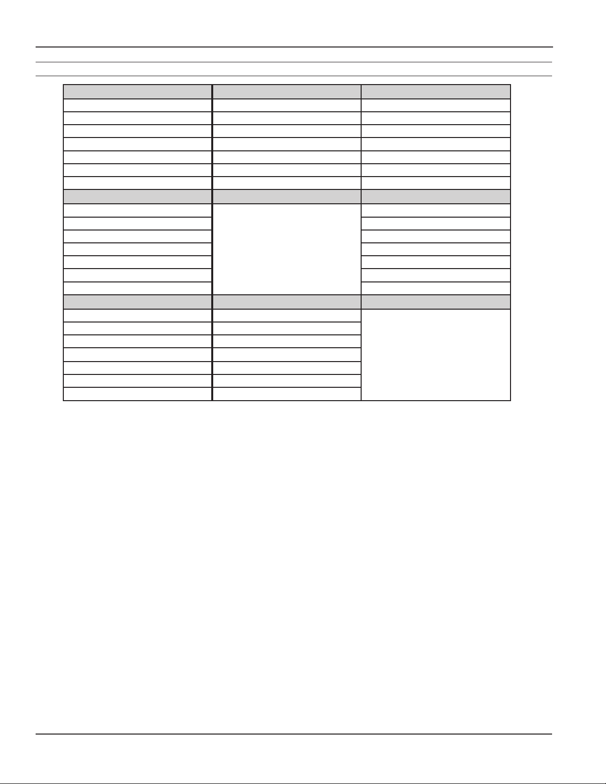
Pulse Output Function Table
PULSE OUTPUT 1 (SCALED) DPF143 DPF144
TYPE Current sinking Current sinking
MAX. VOLTAGE 45 Vdc 45 Vdc
MAX. CURRENT 100 mA 100 mA
MAX. FREQUENCY 6.5 Hz 6.5 Hz
PULSE WIDTH 100 ms 100 ms
ISOLATION 300 V 300 V
CONFIGURABLE AS ALARM YES (High or Low) YES (High or Low)
PULSE OUTPUT 2 (SCALED) DPF143 DPF144 (Note 2)
TYPE
MAX. VOLTAGE 45 Vdc
MAX. CURRENT 100 mA
MAX. FREQUENCY 6.5 Hz
PULSE WIDTH 100 ms
ISOLATION 300 V
CONFIGURABLE AS ALARM YES (High or Low)
PULSE OUTPUT 2 (PASS-THROUGH) DPF143 DPF144
TYPE Current sinking
MAX. VOLTAGE 45 Vdc
MAX. CURRENT 10 mA
MAX. FREQUENCY
PULSE WIDTH SAME AS SENSOR INPUT
ISOLATION 300 V
CONFIGURABLE AS ALARM NO
NOTE 1: 150 V effective isolation when using Omega micropower sensors. • NOTE 2: With 2000 ohm or lower pull-up resistance.
2000 Hz
Not Available
NOTE 2
DPF143/144 SERIES INSTRUCTIONS
Current sinking
Not Available
Page 6 omega.com
Page 7
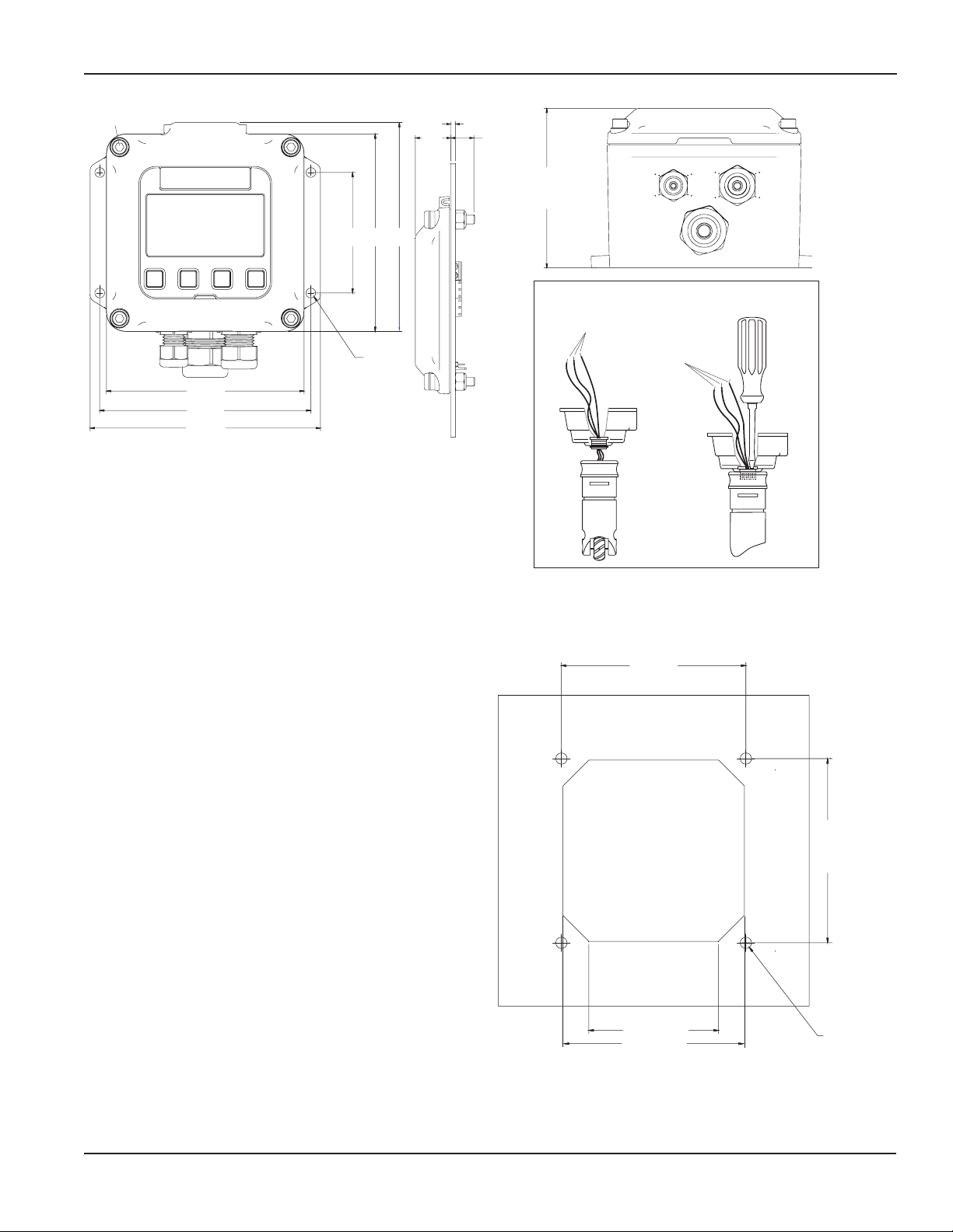
INSTALLATION
3.374
4.77 (121.2)
(110)
#10
.10"
.50"
DPF143/144 SERIES INSTRUCTIONS
Screw
4.10 (104.1)
4.35 (110.5)
2.50
(63.5)
4.10
(104.1)
#10
Screw
0.10 (2.5)
0.78
.78"
(19.8)
4.33
Dimensions are in Inches (Millimeters)
Wall Mount. To mount an DPF143/144 indicator to the
wall, hold the unit in the desired position, mark the holes
in the mounting feet, drill and mount with screws. A metermounted indicator can be converted to a wall mount using
an adapter mounting kit.
0.50
(12.7)
3.37
(85.6)
Meter Mount
Sensor Wires
Sensor Wires
Meter Mount. If the DPF143/144 indicator was ordered
as a meter mount model, the housing is already mounted
directly to the ow sensor and needs no further installation.
Panel Mount. Using the “Panel Cutout” drawing as a guide,
cut a hole in the panel. Place the DPF143/144 indicator on
the panel and mark the holes, drill, and mount with the
supplied screws and washers.
An DPF143/144 module can be converted from a wall-
3.56 (90.4)
mount to a meter-mount using the mounting kit that
includes a lower housing and associated hardware and
installs as follows:
1. Remove the strain relief through which the ow
sensor cable runs.
2. Cut the cable to about 6” in length. Carefully strip
the cable jacket to expose the three colored wires
(red, white, and black) inside.
3. Route the wires through the threaded connector
Panel Cutout
3.56
(90.4)
pre-installed in the bottom of the housing.
4. Start the threaded connector into the female thread
on the top of the ow sensor. Be sure to match the
oblong shape on the bottom of the housing to the
depression on the top of the ow sensor.
5. Using an ordinary screwdriver inserted in one side
of the slot (see drawing), tighten the screw as much
as possible.
6. Strip the wire ends, make the connections to the
2.4 (61) TYP
3.5 (88.9) TYP
(PANEL CUTOUT)
.218 (5.5)
indicator as shown in Connections Diagrams, and
then use the cover screws to attach the indicator to
the top of the housing.
Page 7 omega.com
Page 8
CONNECTION DIAGRAMS
Sensor
DPF143/144 SERIES INSTRUCTIONS
Connections
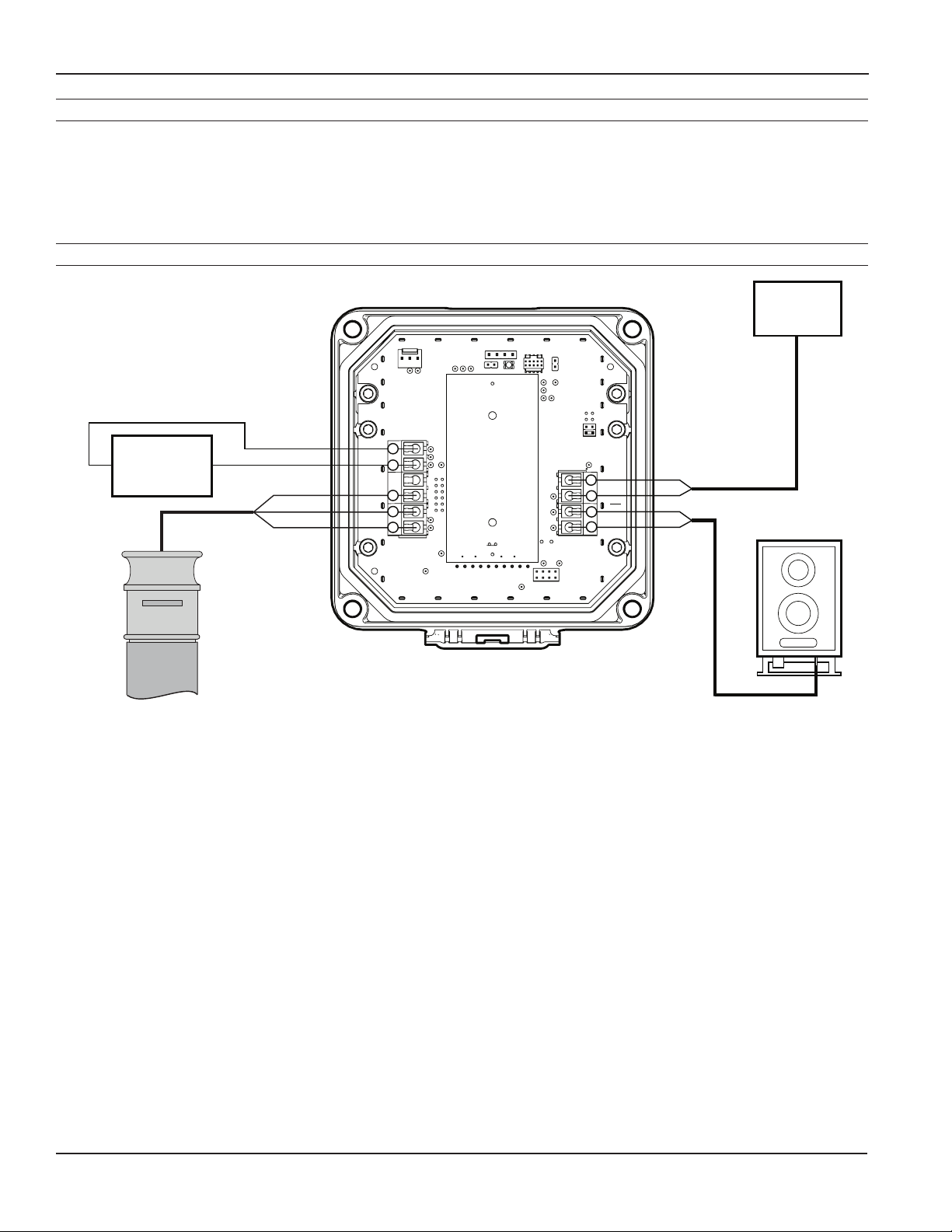
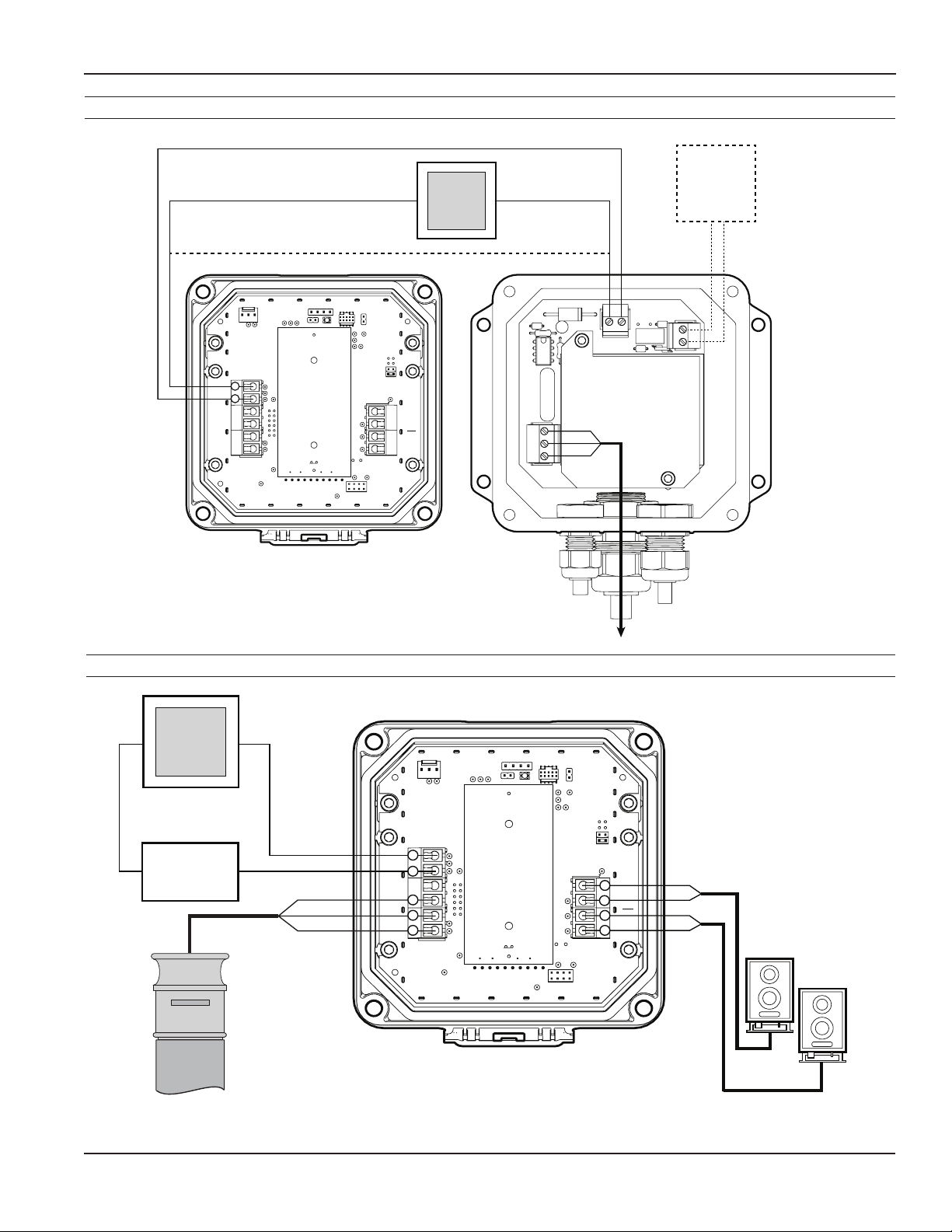
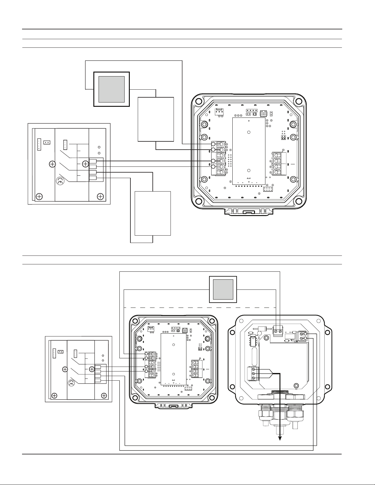
To connect the ow computer to a ow sensor or an external device such as a chemical metering pump, follow the
Standard Connections diagrams on this and the following pages.
Connections for DPF143/3-Wire Mechanical Meter
DPF143
FT430
POWER
_
SENSOR
S
_
+
ENGD
_
+
+
_
S
+
_
PULSE
OUT 2
_
+
+
_
PULSE
OUT 1
_
+
+
_
7-45Vdc
+
Supply
BLACK
WHITE
RED
Pulse
Pass-thru
Pulse Responsive
Metering Pump
Flow
Page 8 omega.com
Page 9
CONNECTION DIAGRAMS
POWER
SENSOR
ENGD
+
_
_
+
S
PULSE
OUT 2
PULSE
OUT 1
+
_
+
_
RED
WHITE
BLACK
+
_
9-30 Vdc
Loop Power
Supply
Flow
Sensor
FT440
Electronic
Metering Pumps
_
+
S
_
+
_
+
_
+
4-20mA
Device
+
_
Power Source
Connections for DPF143-DPS/DPF144-DPS—115Vac Option
4-20mA
+
Device
Dashed line shows (-) terminal connection
if 4-20mA device is not used (e.g. FT430)
(e.g. DPF143)
DPF143/144 SERIES INSTRUCTIONS
12V
_
Device
_
+
POWER
_
_
+
+
ENGD
_
SENSOR
S
+
FT430/FT440
DPF143/DPF144
_
PULSE
OUT 2
+
PULSE
OUT 1
_
+
DPF143-DPS
FT430-139
FT440-139
DPF144-DPS
(Dual Power Supply)
L
N
G
Lower Housing
Connections for DPF144/3-wire Mechanical/ Dual Scaled Pulse Out
DPF144
BLACK
WHITE
GREEN
_
24Vdc
+
To 115Vac
12Vdc
_
+
Page 9 omega.com
Page 10
CONNECTION DIAGRAMS
Red
Connections for DPF144/FMG900/980 Series
DPF143/144 SERIES INSTRUCTIONS
+
4-20mA
_
Black
Device
_
9-30 Vdc
Power Supply
Status
Zero
Adj
LED
+
Option
1
Reverse
-
Output
Only
+
2
Max 6mA
30Vdc
12-24Vdc
Output
Power
Forward
3
-
+
4
5
-
+
6
_
+
_
+
White
Green
Black
Red
_
12 Vdc
Power Supply
+
Connections for DPF144-DPS/FMG900/980 Series
Red
DPF144
FT440
POWER
_
_
+
+
SENSOR
S
ENGD
_
+
_
S
_
S
_
PULSE
OUT 2
+
PULSE
OUT 1
_
+
_
L
N
G
DPF144-DPS
FT440-139
(Dual Power Supply)
Lower Housing
BLACK
WHITE
GREEN
_
24Vdc
+
12Vdc
To 115Vac
Power Source
_
_
+
+
Zero
Adj
Reverse
-
Output
+
Max 6mA
30Vdc
Forward
Output
-
+
12-24Vdc
-
Power
+
EX Magmeter
4-20mA
+
Device
Status
LED
Option
1
Only
2
3
4
5
6
_
+
_
+
Dashed line shows (-) terminal connection
if 4-20mA device is not used
POWER
_
_
+
+
White
Green
Black
Red
ENGD
_
SENSOR
S
+
FT440
DPF144
_
s
_
PULSE
OUT 2
+
PULSE
OUT 1
_
+
Page 10 omega.com
Page 11
0.00
0
SETTINGS
10031295
MF81T-P200
K: 53.6
DPF143/144 SERIES INSTRUCTIONS
K-Factor
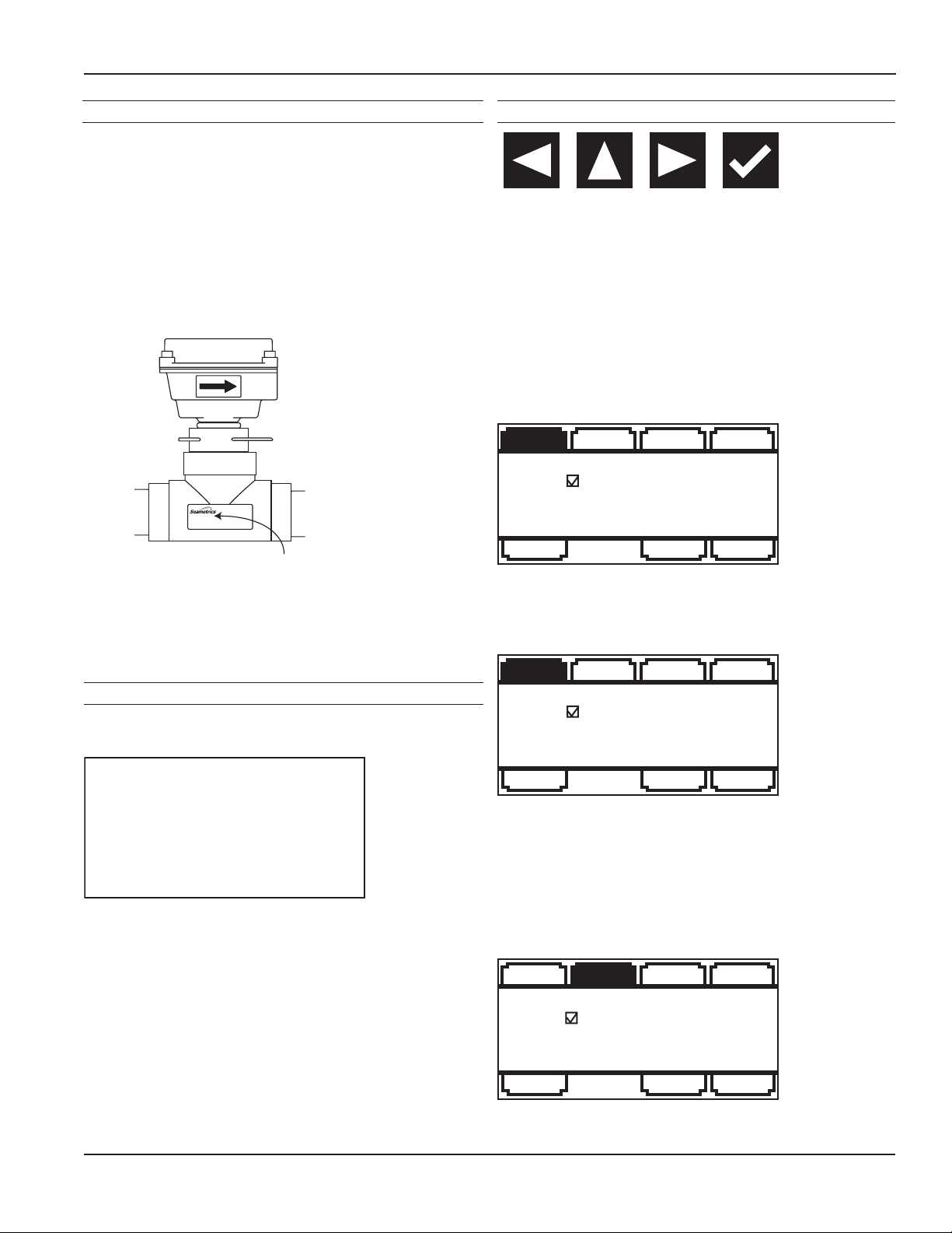
At a minimum, every DPF143/144 ow computer must be
programmed with the “K-factor”. (This is the number of
pulses that the meter produces per gallon of ow.) If you
wish to read in units other than gallons, see below.
The K-factor on any Omega ow sensor tting or in-line
meter can be found on the model-serial label. The line
reading K = xxxx gives the desired number. For depthadjustable sensors (110, 210, 150, 250 models).
Fixed Depth Meter
Find Your K-Factor Here
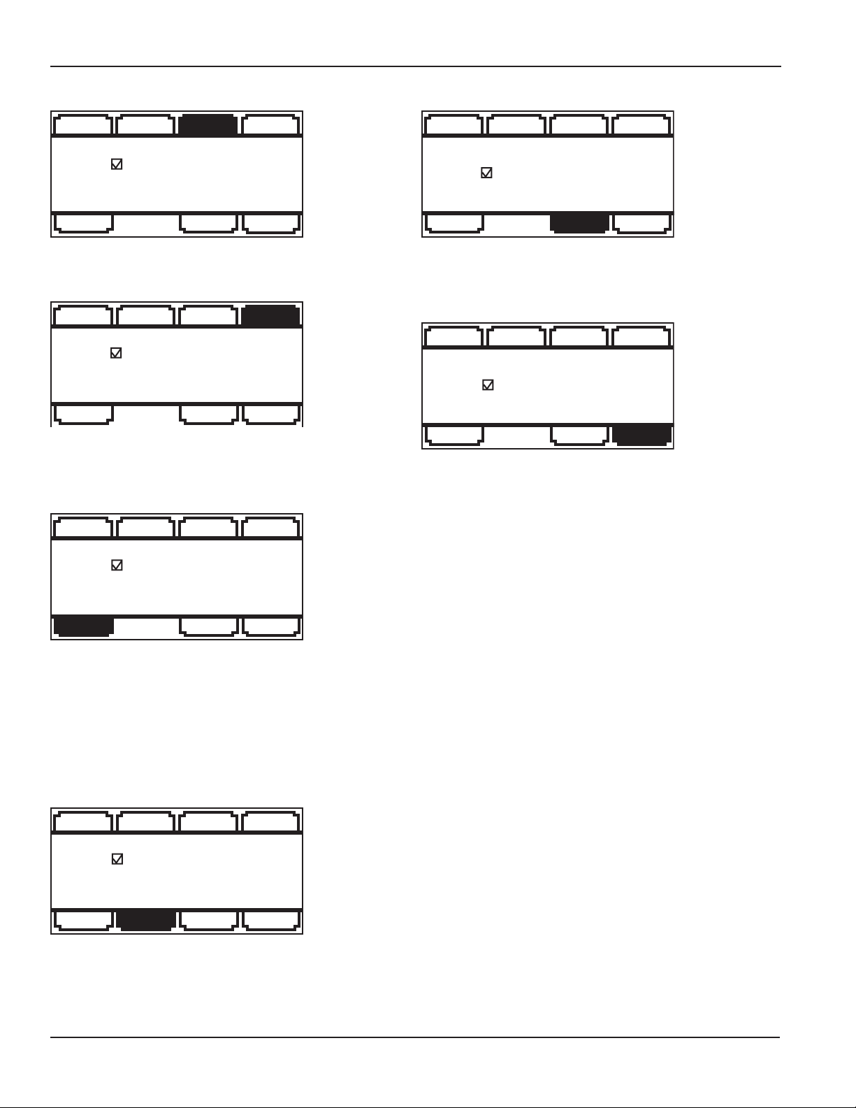
Menu Navigation
The left/right keys are used to move through the menus
and position the cursor during data entry. The up arrow is
used to scroll through the available values that are to be
entered. (examples: numerical values for K factor entry or
selection of units from the available options) The enter key
(represented on the keypad by the check mark) is used to
save selected entries and in conjunction with the exit tab to
move between menu screens. As one navigates the menus
the current parameter setting is shown and instructions are
displayed for how to change the selected parameter.
MAIN MENU
R UNITSET K T UNIT SET D
086238.235
PRESS TO SET NUMBER
OF PULSES RECEIVED PER
GALLON OF FLOW
SET P RESET EXIT
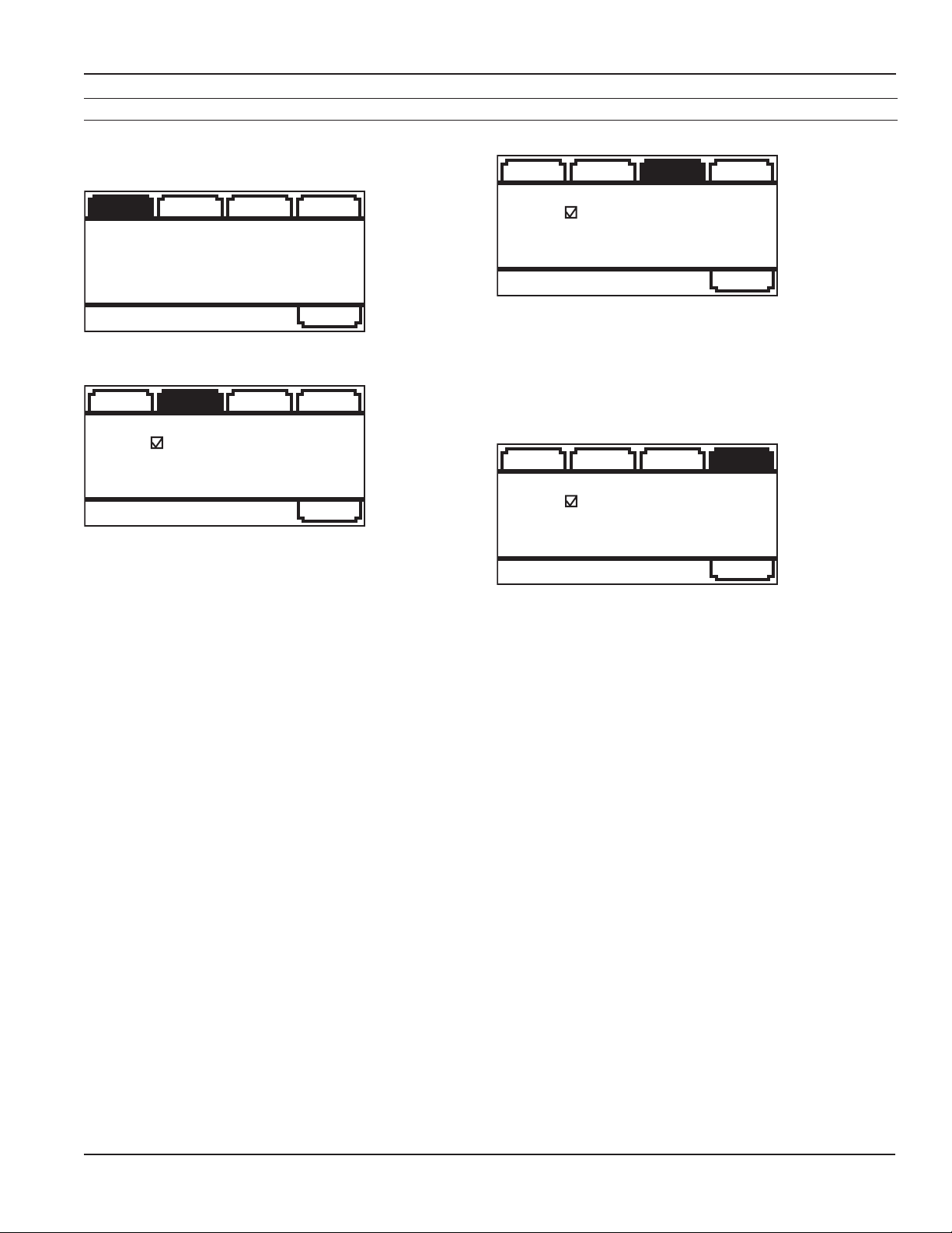
All menu screens consist of two rows of tabs surrounding a
dialog box that lets you view and change setup parameters.
Changing Flow Indicator Settings
THE HOME SCREEN
GPD
MID
The HOME Screen, shown above, is the normal screen
which displays TOTAL ow volume and ow RATE. The Four
buttons below the LCD display are used to access menu
screens for viewing and changing setup parameters.
SET K
R UNITSET K T UNIT SET D
086238.235
PRESS TO SET NUMBER
OF PULSES RECEIVED PER
GALLON OF FLOW
SET P RESET EXIT
View or change the K factor. The K factor is the number of
pulses the ow sensor provides for every gallon of ow.
(Note that the decimal is xed at three places. If you only
have two decimal places for your K-factor, enter a zero for
the third digit. If unable to set K-factor, the unit is "locked"
to prevent tampering.
R UNIT
R UNITSET K T UNIT SET D
FLOW RATE = GPD
PRESS TO SET UNITS
FOR DISPLAY
SET P RESET EXIT
View or change the ow rate units
Page 11 omega.com
Page 12
SETTINGS
DPF143/144 SERIES INSTRUCTIONS
T UNIT
R UNITSET K T UNIT SET D
TOTAL = GALLONS
PRESS TO SET UNITS
FOR DISPLAY
SET P RESET EXIT
View or change the total volume units
SET D
R UNITSET K T UNIT SET D
000
PRESS TO CHOOSE
NUMBER OF DECIMAL PLACES
IN TOTAL DISPLAY
SET P RESET EXIT
View or change the number of decimals displayed in the
total volume display
SET P OR SET A
R UNITSET K T UNIT SET D
00000.0 GALLONS
PRESS TO SET NUMBER OF
GALLONS TOTALIZED PER
PULSE SENT OUT PULSE1
RESET
R UNITSET K T UNIT SET D
PRESS TO RESET TOTAL
SET P RESET EXIT
Reset the total ow volume to zero. This tab is not available
when the -64 non resettable total option is ordered
EXIT
R UNITSET K T UNIT SET D
PRESS TO EXIT MENU AND
RETURN TO FLOW DISPLAY
SET P RESET EXIT
Return to the home screen, enter a submenu, or accept a
parameter change
The Exit menu also allows access to the secondary menu,
as described on the next page.
SET P RESET EXIT
The factory setting will show Set P which allows one to
view or change the volume of ow totalized per pulse sent
to pulse out 1. The units for Set P follow the units selected
for the rate display. (With EXIT highlighted, pressing the
up arrow four times will allow pulse out 1 to be an alarm.
The alarm can be set to trigger on either a high or low ow
condition as determined by the user.)
SET 20 (DPF144 ONLY)
R UNITSET K T UNIT SET D
00000.0 GALLONS
PRESS TO SET THE FLOW
RATE AT WHICH 20 mA
(MAX) OUTPUT IS DESIRED
SET P RESET EXIT
Input the ow rate at which 20 mA (max) output is desired
SET 20
Page 12 omega.com
Page 13
SETTINGS
The DPF144 Secondary Menu Functions
DPF143/144 SERIES INSTRUCTIONS
When using the DPF144, a secondary menu is available with
further options. Enter the secondary menu by pressing the
up arrow four times while EXIT is highlighted.
OUTPMAIN INPP CODE
SCROLL TO SELECT A
SUBMENU AND CHANGE
FEATURES
EXIT
OUTP
OUTPMAIN INPP CODE
PRESS TO SET ALARMS,
PULSE OUT, AND 4-20 mA
EXIT
View or change the function of Set P tab on the main menu.
INP
OUTPMAIN INP P CODE
PRESS TO SET F, J, REED
AND PULSE INDICATOR
EXIT
View or change the lter (set F), jitter (set J), enable reed
mode. Use the lter setting if the display is jumping
excessively due to ow conditions. Use the jitter setting to
enter a time delay to handle start up conditions. Jitter units
are seconds.
PCODE
OUTPMAIN INP P CODE
PRESS TO SET PASSCODE
AND CHANGE PROTECTED
FEATURES
EXIT
The P/A tab changes the function of the outputs. Default
is scaled pulse out for both outputs. Either output can be
changed to alarm high or alarm low. If alarm options are
selected menu tabs for setting the alarms will be displayed
on the main menu (alarm 1) or the secondary menu (alarm
2) If the alarm options are selected a Set H (hysteresis) tab
is available. The hysteresis entry is a % value. The value
denes the % change required for a change in alarm state
to occur.
The factory setting will show Set P2 which allows one to
view or change the volume of ow totalized per pulse
sent to pulse out 2. The units for Set P2 follow the units
selected for the rate display. If P2 is selected as an alarm
the menus will change to Set A2 and a Set H (hysteresis)
tab is available. The hysteresis entry is a % value. The value
denes the % change required for a change in alarm state
to occur.
Set 4 input the ow rate at which 4 mA (min) output is
desired.
ADJ L allows the adjustment of the 4 mA and 20 mA values
so that one can tune performance of the DPF144 to match
the installed system values. The adjustment units range
from 0-32. Positive values adjust the setting incrementally
larger and negative values adjust the setting incrementally
lower.
Enter the pass code for access to protected features.
Protected Features
To enter the protected features use the left/right arrow
keys to navigate to the Pcode tab, found in the secondary
menu. Press the enter key and then enter the pass code.
The protected menu, shown below, will now be displayed.
The tabs have the following functions:
Set CD Enter a user created numerical pass code.
Lock Lock menu functions to prevent unauthorized
changes.
E/D R Disable or enable the total volume reset
function.
PCNT Keeps a running tally of the number of times
the pass code has been used.
Page 13 omega.com
Page 14

TROUBLESHOOTING
Problem Probable Causes Things to try…
Display blank No power to the unit Check for minimum 12 Vdc at power terminals
Short in sensor circuit Disconnect sensor, see if display returns (zero ow
rate)
Display is in sleep mode Push any button to reactivate display. (Display goes
to sleep after about 3 minutes of non-use.)
Display missing pixels Damaged display module Contact Omega for return/replacement
DPF143/144 SERIES INSTRUCTIONS
Display showing meaningless
characters
Display reads normally but ow
rate incorrect
Display reads normally but
incorrect pulse output
Display reads normally, but no
(or incorrect) 4-20mA output
(DPF144 only)
Display reads zero when there
is ow
Display reads ow rate when
there is none
Unit's microcontroller crashed Disconnect and reconnect power. If problem
repeats, contact distributor for return/replacement.
Wrong K-factor or time base
entered
Wrong pulse output setting Use "Set P" to correct pulse output setting
Polarity reversed on pulse output
terminals
Wrong 4mA setting or wrong 20mA
setting
Inadequate loop power supply
voltage
Polarity incorrect in 4-20mA loop
circuit
Flow sensor failed Consult ow sensor manual for how to test
Break in ow sensor circuit Check for continuity with multimeter
Long ow sensor wire, running
parallel to power wires
Flow sensor malfunction See ow sensor manual to check
Enter correct K-factor from meter, tting, or manual
Reverse leads
Use "Set 4" to correct target minimum ow rate.
Use "Set 20" to correct target top ow rate.
Check voltage (For 4-20mA applications, 24 Vdc is
recommended)
Compare to Connections diagram
Reroute wire or change to shielded wire
Flow "jitter" (oscillating slosh) reads
as ow
Totalizer does not always
appear to display the total ow
Page 14 omega.com
Break in power to meter The totalizer's memory is only updated every 15
Consult factory for "anti-jitter" setting
minutes. If power is lost, the totalizer will retain the
value last written but will not be updated to reect
any ow between the last write and the time the
power was lost.
Page 15

WARRANTY/DISCLAIMER
OMEGA ENGINEERING, INC. warrants this unit to be free of defects in materials and workmanship for a
period of 13 months from date of purchase. OMEGA’s WARRANTY adds an additional one (1) month
grace period to the normal one (1) year product warranty to cover handling and shipping time. This
ensures that OMEGA’s customers receive maximum coverage on each product.
If the unit malfunctions, it must be returned to the factory for evaluation. OMEGA’s Customer Service
Department will issue an Authorized Return (AR) number immediately upon phone or written request.
Upon examination by OMEGA, if the unit is found to be defective, it will be repaired or replaced at no
charge. OMEGA’s WARRANTY does not apply to defects resulting from any action of the purchaser,
including but not limited to mishandling, improper interfacing, operation outside of design limits,
improper repair, or unauthorized modification. This WARRANTY is VOID if the unit shows evidence of
having been tampered with or shows evidence of having been damaged as a result of excessive corrosion;
or current, heat, moisture or vibration; improper specification; misapplication; misuse or other operating
conditions outside of OMEGA’s control. Components in which wear is not warranted, include but are not
limited to contact points, fuses, and triacs.
OMEGA is pleased to offer suggestions on the use of its various products. However,
OMEGA neither assumes responsibility for any omissions or errors nor assumes liability for
any damages that result from the use of its products in accordance with information provided
by OMEGA, either verbal or written. OMEGA warrants only that the parts manufactured by the
company will be as specified and free of defects. OMEGA MAKES NO OTHER WARRANTIES OR
REPRESENTATIONS OF ANY KIND WHATSOEVER, EXPRESSED OR IMPLIED, EXCEPT THAT OF
TITLE, AND ALL IMPLIED WARRANTIES INCLUDING ANY WARRANTY OF MERCHANTABILITY
AND FITNESS FOR A PARTICULAR PURPOSE ARE HEREBY DISCLAIMED. LIMITATION OF
LIABILITY: The remedies of purchaser set forth herein are exclusive, and the total liability of
OMEGA with respect to this order, whether based on contract, warranty, negligence,
indemnification, strict liability or otherwise, shall not exceed the purchase price of the
component upon which liability is based. In no event shall OMEGA be liable for
consequential, incidental or special damages.
CONDITIONS: Equipment sold by OMEGA is not intended to be used, nor shall it be used: (1) as a “Basic
Component” under 10 CFR 21 (NRC), used in or with any nuclear installation or activity; or (2) in medical
applications or used on humans. Should any Product(s) be used in or with any nuclear installation or
activity, medical application, used on humans, or misused in any way, OMEGA assumes no responsibility
as set forth in our basic WARRANTY/DISCLAIMER language, and, additionally, purchaser will indemnify
OMEGA and hold OMEGA harmless from any liability or damage whatsoever arising out of the use of the
Product(s) in such a manner.
RETURN REQUESTS/INQUIRIES
Direct all warranty and repair requests/inquiries to the OMEGA Customer Service Department.
BEFORE RETURNING ANY PRODUCT(S) TO OMEGA, PURCHASER MUST OBTAIN AN AUTHORIZED
RETURN (AR) NUMBER FROM OMEGA’S CUSTOMER SERVICE DEPARTMENT (IN ORDER TO AVOID
PROCESSING DELAYS). The assigned AR number should then be marked on the outside of the return
package and on any correspondence.
The purchaser is responsible for shipping charges, freight, insurance and proper packaging to prevent
breakage in transit.
FOR WARRANTY RETURNS, please have the
following information available BEFORE contacting
OMEGA:
1. Purchase Order number under which the product
was PURCHASED,
2. Model and serial number of the product under
warranty, and
3. Repair instructions and/or specific problems
relative to the product.
OMEGA’s policy is to make running changes, not model changes, whenever an improvement is possible. This affords
our customers the latest in technology and engineering.
OMEGA is a registered trademark of OMEGA ENGINEERING, INC.
© Copyright 2016 OMEGA ENGINEERING, INC. All rights reserved. This document may not be copied, photocopied,
reproduced, translated, or reduced to any electronic medium or machine-readable form, in whole or in part, without the
prior written consent of OMEGA ENGINEERING, INC.
FOR NON-WARRANTY REPAIRS,
OMEGA for current repair charges. Have
the following information available BEFORE
contacting OMEGA:
1. Purchase Order number to cover the COST
of the repair,
2. Model and serial number of the product, and
3. Repair instructions and/or specific problems
relative to the product.
consult
Page 16

Where Do I Find Everything I Need for
Process Measurement and Control?
OMEGA…Of Course!
Shop online at omega.com
TEMPERATURE
MU
Thermocouple, RTD & Thermistor Probes, Connectors, Panels & Assemblies
MU
Wire: Thermocouple, RTD & Thermistor
MU
Calibrators & Ice Point References
MU
Recorders, Controllers & Process Monitors
MU
Infrared Pyrometers
PRESSURE, STRAIN AND FORCE
MU
Transducers & Strain Gages
MU
Load Cells & Pressure Gages
MU
Displacement Transducers
MU
Instrumentation & Accessories
FLOW/LEVEL
MU
Rotameters, Gas Mass Flowmeters & Flow Computers
MU
Air Velocity Indicators
MU
Turbine/Paddlewheel Systems
MU
Totalizers & Batch Controllers
SM
pH/CONDUCTIVITY
MU
pH Electrodes, Testers & Accessories
MU
Benchtop/Laboratory Meters
MU
Controllers, Calibrators, Simulators & Pumps
MU
Industrial pH & Conductivity Equipment
DATA ACQUISITION
MU Communications-Based Acquisition Systems
MU Data Logging Systems
MU Wireless Sensors, Transmitters, & Receivers
MU Signal Conditioners
MU Data Acquisition Software
HEATERS
MU
Heating Cable
MU
Cartridge & Strip Heaters
MU
Immersion & Band Heaters
MU
Flexible Heaters
MU
Laboratory Heaters
ENVIRONMENTAL
MONITORING AND CONTROL
MU
Metering & Control Instrumentation
MU
Refractometers
MU
Pumps & Tubing
MU
Air, Soil & Water Monitors
MU
Industrial Water & Wastewater Treatment
MU
pH, Conductivity & Dissolved Oxygen Instruments
LT-14388r1.1 20161017
10/17/16
M-5615/1016
 Loading...