

Page 1
DP9800-TC & DP9800-RTD
Temperature Monitor
Page 2

Page 3

2
DP9800 Temperature Monitor
Contents
1. About the DP9800. . . . . . . . . . . . . . . . . . . . . . . . . . . . . . . . . . . . . . . . . . . . . . . . . . . . . . . . . . . . . . . . 3
2. Installation
. . . . . . . . . . . . . . . . . . . . . . . . . . . . . . . . . . . . . . . . . . . . . . . . . . . . . . . . . . . . . . . . . . . . . . . 4-5
Front panel
. . . . . . . . . . . . . . . . . . . . . . . . . . . . . . . . . . . . . . . . . . . . . . . . . . . . . . . . . . . . . . . . . . . . . . . . . . 4
Rear panel
. . . . . . . . . . . . . . . . . . . . . . . . . . . . . . . . . . . . . . . . . . . . . . . . . . . . . . . . . . . . . . . . . . . . . . . . . . . 4
Supply connection
. . . . . . . . . . . . . . . . . . . . . . . . . . . . . . . . . . . . . . . . . . . . . . . . . . . . . . . . . . . . . . . . . . . 4
Communication interface
. . . . . . . . . . . . . . . . . . . . . . . . . . . . . . . . . . . . . . . . . . . . . . . . . . . . . . . . . . . . 4
Sensor connections
. . . . . . . . . . . . . . . . . . . . . . . . . . . . . . . . . . . . . . . . . . . . . . . . . . . . . . . . . . . . . . . . . . 5
3. Operation
. . . . . . . . . . . . . . . . . . . . . . . . . . . . . . . . . . . . . . . . . . . . . . . . . . . . . . . . . . . . . . . . . . . . . . 6-18
a) Stand alone
. . . . . . . . . . . . . . . . . . . . . . . . . . . . . . . . . . . . . . . . . . . . . . . . . . . . . . . . . . . . . . . . . . . . . . . 6
To read sensor temperatures directly
To scroll through all channels
b) Use with a PC
. . . . . . . . . . . . . . . . . . . . . . . . . . . . . . . . . . . . . . . . . . . . . . . . . . . . . . . . . . . . . . . . . . . . 6
Install the software
. . . . . . . . . . . . . . . . . . . . . . . . . . . . . . . . . . . . . . . . . . . . . . . . . . . . . . . . . . . . . . . 6
Control panel
. . . . . . . . . . . . . . . . . . . . . . . . . . . . . . . . . . . . . . . . . . . . . . . . . . . . . . . . . . . . . . . . . . . . 7
Sensor type selection
. . . . . . . . . . . . . . . . . . . . . . . . . . . . . . . . . . . . . . . . . . . . . . . . . . . . . . . . . . . . 8
System Configuration
. . . . . . . . . . . . . . . . . . . . . . . . . . . . . . . . . . . . . . . . . . . . . . . . . . . . . . . . . . . . 9
Comms port
. . . . . . . . . . . . . . . . . . . . . . . . . . . . . . . . . . . . . . . . . . . . . . . . . . . . . . . . . . . . . . . . 9
DP9800 settings
. . . . . . . . . . . . . . . . . . . . . . . . . . . . . . . . . . . . . . . . . . . . . . . . . . . . . . . . . . . . . 9
Chart recorder display
. . . . . . . . . . . . . . . . . . . . . . . . . . . . . . . . . . . . . . . . . . . . . . . . . . . . . . . . . . 10
PC logging
. . . . . . . . . . . . . . . . . . . . . . . . . . . . . . . . . . . . . . . . . . . . . . . . . . . . . . . . . . . . . . . . . . . . . . 10
DP9800 on-board logging
. . . . . . . . . . . . . . . . . . . . . . . . . . . . . . . . . . . . . . . . . . . . . . . . . . . . . . . 11
Calibration checking; DP9800-TC, thermocouple version
. . . . . . . . . . . . . . . . . . . . . 12
Re-calibration; DP9800-TC, thermocouple version
. . . . . . . . . . . . . . . . . . . . . . 14
Calibration checking; DP9800-RTD, RTD version
. . . . . . . . . . . . . . . . . . . . . . . . . . . . . . . 16
Re-calibration; DP9800-RTD, RTD version
. . . . . . . . . . . . . . . . . . . . . . . . . . . . . . . 17
4. Specifications
. . . . . . . . . . . . . . . . . . . . . . . . . . . . . . . . . . . . . . . . . . . . . . . . . . . . . . . . . . . . . . . . . 19-20
5. Suggested application; probe comparison calibration
. . . . . . . . . . . . . . . . . . . . . . . 21
Temperature measurements made with the DP9800 are in accordance with
IEC584 & IEC751, ITS90 refers.
Information in this publication may be subject to change.
Page 4

1. About the DP9800
DP9800 USB DIGITAL THERMOMETER/DATA LOGGER
The DP9800 thermometers can be used in conjunction with a PC to provide accurate,
versatile 8 channel temperature measurement, scanning and logging of measured values.
It can also be used as a ‘stand alone’ 8-channel indicator/logger and incorporates a digital
display of measured temperature.
The integral, self-calibration checking facility for the thermocouple version is a rapid and
convenient method for on-site calibration checking and does not require any additional
equipment other than a special, external link. Self-calibration of RTD ranges is equally
simple and uses plug-in precision resistors.
The DP9800 is designed to provide exceptional stability with high measurement
resolution and represents an ideal crossover between plant practicality and laboratory
performance at a very competitive price.
The PC software supplied with the instrument allows control, measure, logging and
calibration functions.
3
DP9800 Temperature Monitor
Page 5

2. Installation
Front panel
Rear Panel
Supply connection
The DP9800 operates from a 6 to 9V dc supply. A suitable 90 to 250V 50/60Hz adaptor
is supplied with the instrument, complete with alternative pin configurations for
international supply outlets.
Connect the adaptor output jack to the supply input socket on the rear panel; an on-off
switch is not fitted, simply connect the supply.
Communication interface
Connect the USB cable supplied between the instrument and the PC.
4
DP9800 Temperature Monitor
DP9800-TC DP9800-RTD
Page 6

Sensor connections
DP9800-TC, thermocouple inputs
Only the appropriate, miniature (flat pin) , colour coded and polarised thermocouple
plug can be used for each input. Any type of thermocouple (eg K,N,T etc) can be
connected to any input but each must be terminated in the correct type of plug, colour
coded to suit the attached thermocouple type.The particular thermocouple type must
be selected for each channel via the PC software.
Any unused input channels are simply ignored; in such cases, the appropriate channel
display will indicate an upscale (high value) reading on both the instrument front panel
and in the PC control panel.
DP9800-RTD, RTD inputs
The DP9800 uses a 3-wire configuration for each input and connections are made to
‘plug-in’ terminal blocks. If a 4-wire probe is used, the 4th wire (either red or white) is
left unconnected and , if necessary, insulated to avoid any crossconnection contact.
If a 2 wire connection is used, connect the red and white wires
as shown in the diagram and link terminals C & B.
Sensor connections can be made with the terminal block in-situ
(plugged in to the rear panel) or the block can be unplugged
from the instrument if preferred.
Any unused inputs are simply ignored; in such cases, the
appropriate channel display will indicate an upscale (high value) reading on both the
instrument front panel and in the PC control panel.
5
DP9800 Temperature Monitor
DP9800-TC
DP9800-RTD
C B A
Red
Red
White
Page 7

3. Operation
The DP9800 can be used with or without a PC as required. For the optimum accuracy,
especially in the case of the thermocouple version (DP9800-TC), the instrument should
be allowed due time to ‘settle’ in the ambient temperature of its location before use.This
is important if it is moved between locations of greatly different ambient temperatures.
a) Stand alone without PC
With power and sensor(s) connected, the instrument can be simply used as a
convenient, accurate single or multi-channel digital thermometer. It can also be
used on a stand alone basis even if it has been configured for logging; in this case, the
message ‘logging’ will appear on the display at ‘power up’.
On-board logging can be started without the need for connection to a PC; press
the front panel key just before connecting power to the instrument and keep it
pressed for a few seconds after power-up until ‘logging’ appears on the display.
Logging commences and up to 512 sets of 8 channel readings can be stored.The
logging interval will be whatever value was last selected via the PC software.
Logging will cease when the instrument is powered-down or when ‘off’ is selected
from the PC with communications established. Stored data can be downloaded to
file (in .csv format) on the PC by clicking ‘download’ in the system configuration
window.
The single front panel key can be pressed sequentially to select any required
channel or, when pressed for 3 seconds, will initiate auto scrolling through all
channels.The channel number is displayed along with the temperature indication
from the sensor connected to that particular input.
If any additional functions are required, e.g. configuration, logging set-up or calibration,
then it is necessary to use a PC running the user software and connected via the USB
interface.
b) Use with a PC
For use with a PC, the software supplied with the DP9800 must be installed on
the PC and communication established via the USB lead supplied (online, green
indicator flashing). System requirements for installing the DP9800 software:
Windows XP with at least one USB port. All WINDOWS operating systems
prior to XP do not support USB natively and are not recommended.
Create a folder for the software; logged data will be saved to this folder.
Connect the USB cable supplied between a PC USB port and the DP9800 USB
port before running the PC software.
6
DP9800 Temperature Monitor
Page 8

Control panel
In the DP9800 software window, double click on the ‘DP9800 Control Panel’ icon.
The following window is opened:
The online indicator flashes green when communications between the DP9800 and the
PC are established (see System configuration on next page).
The PC software automatically opens the Control Panel appropriate to either the
DP9800-TC or DP9800-RTD as connected. To reset at any time, if needed, click on
‘Refresh’ in the System Configuration (config/logging) window.
The eight channels readout will display either temperature or millivolts (DP9800-TC) or
Ohms (DP9800-RTD) is selected in the ‘display’ box on the control panel.
7
DP9800 Temperature Monitor
DP9800-TC Control Panel
DP9800-RTD Control Panel
Page 9

Sensor selection
To find out which type of thermocouple is selected for each channel with the DP9800TC, simply double click on the channel readout; the selection can be simply changed by
clicking on the arrow in the ‘T/C type’ box and clicking on the desired type and then
‘send’.
Note:The ‘calibration’ box in the window, may show y =mx +c with pre-determined
values for m&c which are offset correction values allocated during production. These
must not be altered and can be ignored.
Sensor selection is not applicable to the DP9800-RTD which is configured for
RTD, 3 wire on all inputs.
8
DP9800 Temperature Monitor
DP9800-TC, configure
thermocouple type
DP9800-RTD Control Panel
Page 10

System configuration:
Click on ‘configure/logging’ in the lower, left-hand corner of the window; the following
‘system configuration’ window is opened (the same window for ‘-TC’ & ‘-RTD’:
In this window, the Comms Port is selected and instrument settings are made.
Comms Port – Select the required port if this is not done automatically.
The online indicator flashes green when communications between the DP9800 and the
PC are established.
DP9800 settings
i) The DP9800 internal clock date & time are set to user defined values or PC clock
if ‘use PC Time’ is checked. The internal clock can be set by the user; PC or Internet
date & time can be set in the DP9800 internal clock by checking the ‘PC time’ box &
clicking ‘Send’, unchecking ‘PC time’ & clicking ‘Refresh’.
ii) Auto Scan interval can be entered (2 to 10 seconds) and Autoscan switched on
or off.
iii) °C or °F are selected.
iv) Instrument button ‘beep’ can be selected or switched off. When settings are
completed, click ‘send’ and close the system configuration window. Changes to
settings can be made at any time.
9
DP9800 Temperature Monitor
DP9800 System configuration
Page 11

Chart display
For a chart (analogue) display of the last 40 readings all 8 channels, click on chart; x and
y axes are auto-scaled to suit readings.The chart can be opened and closed as required.
The chart displays a plot of the last 40 readings taken from all 8 channels by the
instrument.
Logging
Logging can be carried out on one of two bases;
c) Real-time PC logging is started by clicking ‘Start’ in the control panel at any time, and
stopped by clicking ‘Stop’. Readings are saved in Notepad in ‘.csv’ format, in the same
folder as that in which DP9800 software resides.
The value of the display on the main window will be logged on the PC.This could be
temperature millivolts or resistance depending on the display setting in the main window.
10
DP9800 Temperature Monitor
DP9800 Chart
DP9800-TC Control Panel shown;
logging key is the same for DP9800-RTD
Page 12

d) DP9800 on-board logging is set up by clicking ‘Configure/logging’ in the control panel.
The following ‘logging control’ window is opened.
The logging interval for each chanel is set up (common) and sent to the instrument by
clicking ‘send’.
Logging is started by selecting ‘on’ in the ‘status’ box and clicking ‘send’. It is stopped by
selecting ‘off ’ and clicking ‘send’.
Logged readings are downloaded to file in ‘.csv’ format in the PC by clicking ‘download’.
Downloading takes approximately 2.5 minutes; status is indicated in the window.The file
will be created in the same folder as used for the PC software.
The PC connection is not required during logging, only when configuring the logging
regime.
Alternatively, logging will commence immediately when the front panel key is
pressed at the same time as the instrument is powered up. Logging will cease
when the instrument is powered down.
The DP9800 can be used ‘manually’ during logging, ie. channels can be
selected individually (or auto-scanned) via the front panel key for
temperature readings.
When the on-board, logged values memory is full (512 sets of 8 readings),
those readings stored first will be overwritten by new values.
11
DP9800 Temperature Monitor
DP9800 System configuration
(identical for both versions)
Page 13

Calibration Checking
The DP9800 is designed to be highly accurate and highly stable as indicated in the
specification. Self-calibration is performed during each A/D (analogue to digital)
conversion cycle for example; routine re-calibration is basically unnecessary.
However, a calibration checking facility is incorporated in the DP9800-TC and
this allows the user to easily and conveniently ascertain if re-calibration is
necessary. This feature will also provide validation of calibration without the need to
submit the instrument to a certified laboratory, an expensive and time consuming
procedure.All that is required in terms of additional equipment for this purpose is a
calibrated DVM (digital voltmeter).
Caution. Re-calibration of the DP9800-TC requires highly accurate calibration
equipment; normal thermocouple instrument calibrators are not sufficiently
accurate for this purpose. Please contact our Technical Sales Department for
guidance on re-calibration.
It is important to allow due time for all items to stabilise at the ambient temperature
before proceeding; this is especially important if any items have been moved from a
location with a different ambient temperature.
The DP9800-PT simply requires the use of 2 precision resistors to achieve the same
level of calibration accuracy. However, these resistors are of exceptionally close
tolerance; please contact our Technical Slaes Department for guidance.
1. Quick calibration check – thermocouple version (DP9800-TC)
PC software must be running and the USB lead connected between DP9800 and
PC with communications established (online indicator in the the control panel
flashing green).
a) Connect the ‘Ref ’ link supplied to the ‘Ref ’ output on the rear panel and to
any of the input sockets as required (it is logical to start with input 1)
12
DP9800 Temperature Monitor
Page 14

b) In the main control panel, click ‘millivolt’ in the display box (just below ch6
readout) The DP9800 display will show the corresponding temperature for a
10mV input to the relevant channel; they can be ignored during this
procedure.
c) Observe the readout value of the chosen channel input. If the calibration of
the instrument is correct, the readout will indicate 10.00(00).
Note:The ‘ref’ value is 10.00mV; the least significant two digits
indicated in the control panel display are 1µV and 0.1µV respectively
i.e. a display of say, 10.0085 indicates an ‘error’ of 8.5µV in 10.00mV
which is negligible and well within specification. In fact, any digits
following 10.00(x,y) can be ignored.
d) Repeat a) and c) above as required for other inputs
e) Disconnect the ‘ref ’ link from the jack and the channel input socket.
f) Click ‘temperature’ in the Display box to resume normal measurement.
In the unlikely event of re-calibration being deemed necessary please contact
Omega or refer to the re-calibration procedure later in this section if suitable
equipment and skills are available.
Note: Untrained personnel must not attempt re-calibration of the
DP9800. Please contact Omega for more information.
13
DP9800 Temperature Monitor
DP9800-TC, milliVolts
Page 15

2. Re-calibration – thermocouple version (DP9800-TC)
To be conducted only by authorised & trained personnel using the
appropriate equipment. Unauthorised re-calibration may invalidate the
instrument warranty and would invalidate any applicable calibration
certificate.
The PC software must be running and the USB lead connected between the
DP9800 and the PC with communications established (online indicator in the
Control Panel flashing green);
Note: The next step will ‘clear’ the resident calibration data; this is a
good time to check that everything is in place for re-calibration.
Click on ‘calibrate’ in the lower, left-hand area of the window.The following ‘calibrate’
window appears.
The CJC display value is for instrument set-up and for information only, it can be
ignored.
Clear the existing calibration data by clicking ‘Reset’ for the selected channel in the
‘calibration’ window.
14
DP9800 Temperature Monitor
DP9800-TC, calibration
Page 16

Zero & Span Calibration DP9800-TC
a) Link all eight thermocouple inputs in parallel and apply 0.0000mV signal to them.
A 61⁄2 digit DVM preferably UKAS certified should be used to check the applied
voltage.
b) Click on the ‘All’ box to the left of the ‘calibration’ window (selects all channels
for calibration). If preferred, individual channels can be calibrated by selecting and
clicking on the appropriate tick box.
c) In the main control panel, click millivolt in the Display box (just below Ch6
readout).
d) Click ‘reset’ and ‘restart’ (this clears the existing calibration data and prepares the
selected channel for calibration).
e) Click ‘next’ when ready.
f) Then follow the procedure as instructed in the dialogue screen to the lower left
of the ‘calibration’ window for span calibration. A 50.0000mV signal is applied to
the input(s). Click next when ready and follow the procedure instructed.
g) When the 50mV calibration is completed, click ‘send’ to complete the procedure.
h) Close the ‘calibration’ window.
i) Remove the mV source from the input connection(s) and re-connect sensors as
required.
j) Click ‘temperature’ in the ‘Display’ box in the main Control Panel to resume
temperature measurement.
Note: m & c values are allocated by the software which computes any
measurement offset values to ensure precise calibration.These are not for
user adjustment.
Factory calibration values can be restored if required by
clicking on ‘Restore’ in the calibration window.
15
DP9800 Temperature Monitor
Page 17
16
DP9800 Temperature Monitor
3. Quick calibration check – RTD version (DP9800-RTD)
The PC software must be running and the USB lead connected between the DP9800 and
the PC.
With communications established (online indicator in the Control Panel flashing green);
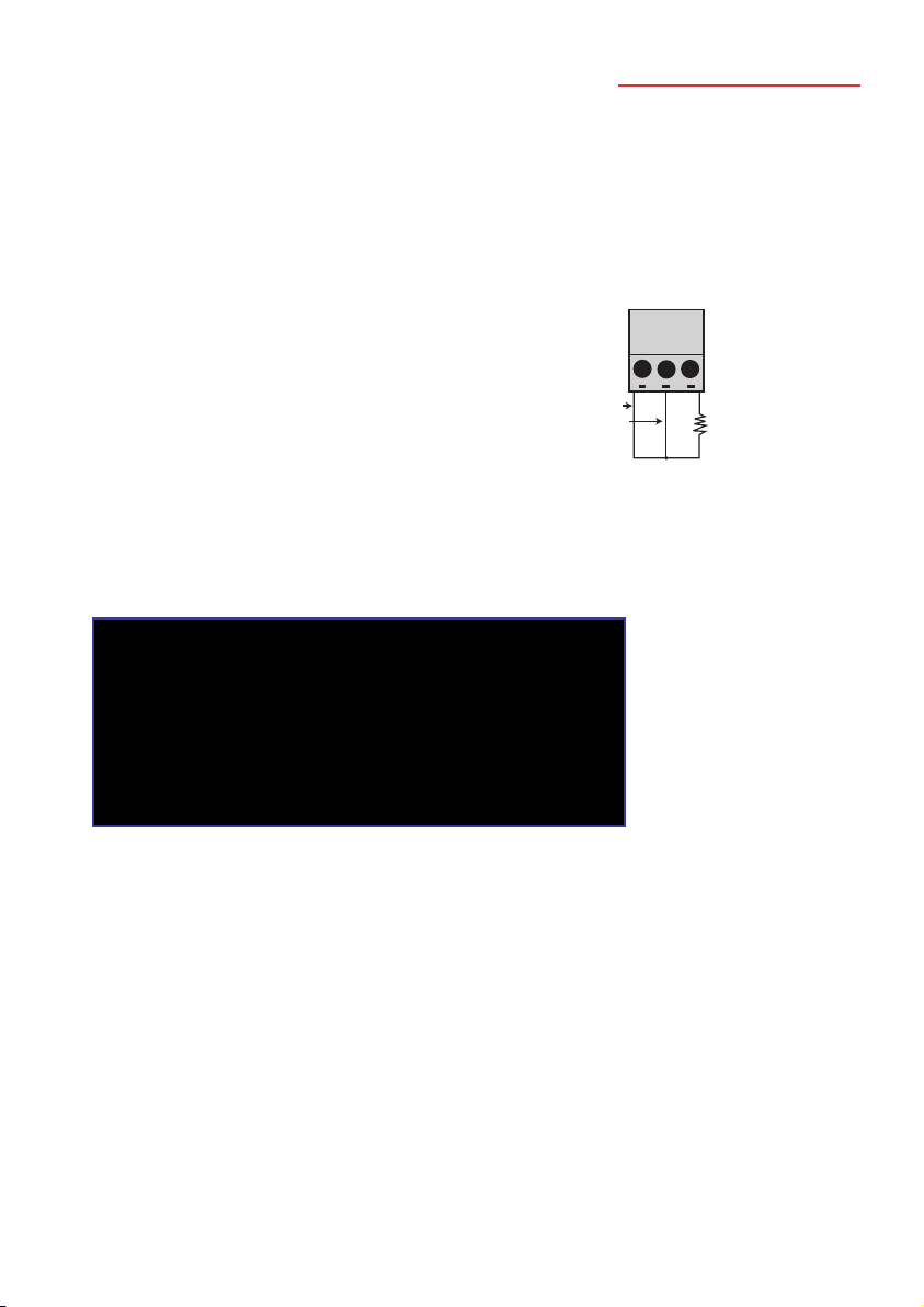
a) Connect the 100.000 Ohm precision resistor
between terminals A & B on input 1 (or other
input to choice). Link terminals B & C with copper
wire if a third wire is not fitted to the resistor.
b) In the main Control Panel, click ‘resistance’ in the display box (just below ch6
readout).The DP9800 display will show the corresponding temperature for a
100 Ohm input (0°C) to the relevant channel; this can be ignored during this
procedure.
c) Select the desired channel for calibration by clicking the appropriate check box.
d) Observe the readout value of the chosen channel. If the calibration of the
instrument is correct, the readout will indicate 100.000 Ohms (the least significant
digit is 1m Ohm and can be ignored.
Active input filtering is applied at a level determined by the software;
time must be allowed for the reading to settle (up to 5 minutes).
This is important during calibration procedures.
e) Repeat a) and c) above as required for other channels.
f) Repeat a) to d) above using the 350.00 Ohm precision resistor.
DP9800-RTD Control Panel
C B A
Red
Red
White
Page 18

4. Re-calibration of RTD version (DP9800-RTD)
To be conducted only by authorised and trained personnel using the
appropriate equipment. Unauthorised re-calibration may invalidate the instrument
warranty and would invalidate any applicable calibration certificate.
The PC Software must be running and the USB lead connected between the DP9800
and the PC, with communications established (on-line indicator in the control panel
flashing green).
Note: The next step will ‘clear’ the resident calibration data; this is a good
time to check that everything is in place for re-calibration.
Click on ‘calibrate’ in the lower left-hand area of the window.The following ‘calibrate’
window appears:
Clear the existing calibration data by clicking ‘Reset’ for the selected channel in the
calibration window.
17
DP9800 Temperature Monitor
DP9800-RTD, calibration
Page 19

Zero & Span calibration DP9800-RTD
a) Connect a 100.00 Ohm precision resistor to input 1 as indicated in 3a) and enter
this value in the top R box to the left.
b) Click on the ch1 check box to select ch1 for calibration.
c) In the main control panel, click ‘resistance’ in the display box (just below ch6
readout).
d) Click ‘reset’ and ‘restart’ (this clears the existing calibration data and prepares the
selected channel for calibration).
e) Click ‘next’ when ready.
f) Then follow the procedure as instructed in the dialogue screen to the lower left
of the ‘calibration’ window. Connect a 350.00 Ohm precision resistor in to input
1, in place of the 100.00 Ohm resistor and enter this value in the lower R box.
g) Click ‘next’ when ready and follow the procedure as instructed.
h) When the 350.00 Ohm calibration is completed, channel 1 is calibrated.
i) Click ‘send’
j) Repeat steps a) to j). for the other channels, clicking the checkbox for each
channel as selected.
k) When finished, click ‘send’ to send the calibration data to the instrument.
l) Close the ‘calibration’ window.
m) Re-connect the sensors as required and click ‘temperature’ in the ‘display’ box in
the main ‘control panel’ to resume temperature measurement.
Other values of calibration resistor can be used if preferred; the chosen value must be
entered in the R box as appropriate.
Note: m & c values are allocated by the software which computes any
measurement offset values to ensure precise calibration.These are not for
user adjustment.
Factory calibration values can be restored if required by
clicking on ‘Restore’ in the calibration window.
18
DP9800 Temperature Monitor
Page 20

4. Specifications
at an ambient temperature of 20°C
Input / Ranges
Thermocouple to IEC 584
Type J -200°C to 750°C
Type K -200°C to1200°C
Type T -200°C to 350°C
Type E -200°C to 900°C
Type N 0°C to 1300°C
Type R 0°C to 1760°C
Type S 0°C to 1760°C
Type B 250°C to 1800°C
RTD(Pt100) to IEC751, 3 wire -200°C to 850°C
Note: all inputs are non-isolated and sensors must be of insulated construction.
Accuracy
Thermocouples better than +/- 0.1°C +/-0.1% of span -100°C to span (Zero
J K T E & N to span Type N) +/-0.15% of span -101 to -200°C (J K T & E)
Thermocouples R S & B better than+/-0.1°C +/-0.15% of span
RTD better than +/- 0.05°C +/- 0.1% of span
Linearisation ±0.05°C
Zero drift ±0.01% of span per °C
Span drift ±0.01% of span per °C
Display LCD, backlight
Display resolution Thermocouple ranges 0.1°C
RTD range 0.01°C
User interface Front panel key for channel No. or auto-scan selection. PC software
for all other functions.
Indication Channel No., measured temperature (°C or °F)
Reference junction Automatic, accurate reference
compensation for junction compensation is incorporated
thermocouples for thermocouple ranges
Self calibration User facility incorporated.The instrument auto-calibrates on every
A/D cycle *
Sensor open circuit Upscale indication
detection & indication Independent alarms should be used for Process safety if required
Ambient operating 0 to 50°C
temperature
Storage temperature -20°C to 70°C
Display LCD with backlight
19
DP9800 Temperature Monitor
Page 21

Input Terminations 8 x thermocouple: mini
connectors
8 x RTD, terminal
blocks
PC Interface USB
Power supply 6Vdc (5.5-9.0V) via
universal mains
adaptor (supplied) 120-
250V 50/60Hz
Logging interval 5 seconds to 1 hour
On-board memory 512 sets of readings
PC software Supplied as standard on CD-ROM
Remote control & measure:- Log readings to file Download to PC
Logging, calibration
* The integral, self-calibration facility for
the thermocouple version is a rapid and
convenient method for on-site calibration and
does not require any additional equipment
other than the special, external link
(optional). Self-calibration of RTD ranges is
quickly and conveniently performed using
plug-in precision resistors (optional).
Traceable calibration can be achieved by the
user conveniently and without recourse to a
accredited Laboratory if there is access to a
certified DVM; this can be used to measure
the DP9800 internally generated calibrated
Voltage via the ‘cal port’ presented externally
to the instrument case. Considerable time
and cost saving are achieved by this method.
Ordering
Thermocouple input x8 DP9800-TC
RTD x 8 input DP9800-RTD
Calibration kit DP9800-CALT (external link for thermocouple model).
Included with DP9800-TC
DP9800-CALP (precision resistor set for RTD model)
Custom calibration details on application
Standard accessories The DP9800 is supplied with a power supply adaptor, USB lead,
PC software CD and instruction manual.The DP9800-TC is supplied
with a ‘ref’ link.
Specifications may be subject to change.
20
DP9800 Temperature Monitor
Page 22

5. Suggested application
Probe comparison calibration
Temperature sensors may need to be routinely checked and/or calibrated in accordance
with specified procedures.There are various ways of achieving such compliance which
typically involve sending the sensors to an accredited laboratory for certification, an
expensive and time consuming procedure.
A practical, highly cost effective alternative method is to use an in-house, portable
temperature calibration system from Omega; this provides a rapid and simple method of
sensor checking and traceable calibration ‘on the bench’.
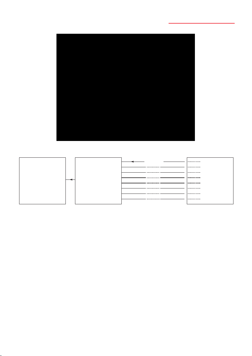
This comprises a thermal reference (dry block) calibrator, a certified reference
thermocouple or thermometer (RTD), a calibrated DP9800 8 channel indicator/logger
and PC software: this, when used with any Windows PC represents a complete solution
for on-site accreditation which allows direct comparison of the probes (up to seven at a
time) with the certified reference sensor. A simple calculation of difference temperature
(if any) between the logged values indicated by the reference and each test probe at a
given, stable temperature (chosen by the user) in the dry block calibrator gives the error
value for each sensor at particular temperatures.The procedure can be repeated for
alternative temperatures set on the dry block as required (e.g. 100, 125, 150°C).
The system can even be used independently of a PC if desired; rather than working
with logged data, readings for each probe can be taken manually by means of the DP9800
front panel key and differences calculated by the user.This is an equally valid procedure.
The design of the dry block ensures that all sensors located in its ‘well’ will be at exactly
the same temperature.The necessary calculations can be performed in a spreadsheet by
applying formulae to the relevant cells and the logged values imported into the
worksheet.
On this basis, the plant probes are traceably calibrated in-house for full compliance with
specified testing and validation procedures.
21
DP9800 Temperature Monitor
Page 23
22
DP9800 Temperature Monitor
USB
1
2
3
4
5
6
7
8
°
°
°
°
°
°
°
°
PC MULTI-CHANNEL
INDICATOR/LOGGER
UP TO 7 PLANT
TEMPERATURE SENSORS
DRY BLOCK
CALIBRATOR
REF PROBE
Page 24

Page 25

 Loading...