

Page 1
DP9601 High Precision Digital
Thermometer / Logger for
RTD Sensors
Page 2

Page 3

2
DP9601 Thermometer
Contents
1. About the DP9601 . . . . . . . . . . . . . . . . . . . . . . . . . . . . . . . . . . . . . . . . . . . . . . . . . . . 3
2. Installation . . . . . . . . . . . . . . . . . . . . . . . . . . . . . . . . . . . . . . . . . . . . . . . . . . . . . . . . . . 5
a. Supply Connection . . . . . . . . . . . . . . . . . . . . . . . . . . . . . . . . . . . . . . . . . . . . . . . . . . 5
b. Communication Interface . . . . . . . . . . . . . . . . . . . . . . . . . . . . . . . . . . . . . . . . . . . . . 5
c. Sensor Connection . . . . . . . . . . . . . . . . . . . . . . . . . . . . . . . . . . . . . . . . . . . . . . . . . . 6
3. Stand Alone Operation . . . . . . . . . . . . . . . . . . . . . . . . . . . . . . . . . . . . . . . . . . . . . . . 7
a. To read sensor temperature directly . . . . . . . . . . . . . . . . . . . . . . . . . . . . . . . . . . . . 9
b. To read differential temperature . . . . . . . . . . . . . . . . . . . . . . . . . . . . . . . . . . . . . . . 9
c. Matching DP9601 to calibrated sensors . . . . . . . . . . . . . . . . . . . . . . . . . . . . . . . . 10
d. SMART probe operation. . . . . . . . . . . . . . . . . . . . . . . . . . . . . . . . . . . . . . . . . . . . . 11
e. Temperature measurement with calibrated sensor . . . . . . . . . . . . . . . . . . . . . . . . 11
f. Using DP9601 to obtain a secondary sensor calibration . . . . . . . . . . . . . . . . . . . 12
g. On-board logging . . . . . . . . . . . . . . . . . . . . . . . . . . . . . . . . . . . . . . . . . . . . . . . . . . 13
h. Error indications . . . . . . . . . . . . . . . . . . . . . . . . . . . . . . . . . . . . . . . . . . . . . . . . . . . 13
i. 3 or 4 wire recognition (RTD). . . . . . . . . . . . . . . . . . . . . . . . . . . . . . . . . . . . . . . . 14
j. Variable filter rate . . . . . . . . . . . . . . . . . . . . . . . . . . . . . . . . . . . . . . . . . . . . . . . . . . 14
4. Operation with a PC . . . . . . . . . . . . . . . . . . . . . . . . . . . . . . . . . . . . . . . . . . . . . . . . 15
a. Install the software . . . . . . . . . . . . . . . . . . . . . . . . . . . . . . . . . . . . . . . . . . . . . . . . . 15
b. Control panel . . . . . . . . . . . . . . . . . . . . . . . . . . . . . . . . . . . . . . . . . . . . . . . . . . . . . 15
c. Sensor indication. . . . . . . . . . . . . . . . . . . . . . . . . . . . . . . . . . . . . . . . . . . . . . . . . . . 16
d. Settings . . . . . . . . . . . . . . . . . . . . . . . . . . . . . . . . . . . . . . . . . . . . . . . . . . . . . . . . . . 16
e. Input channel . . . . . . . . . . . . . . . . . . . . . . . . . . . . . . . . . . . . . . . . . . . . . . . . . . . . . . 17
f. Units and resolution . . . . . . . . . . . . . . . . . . . . . . . . . . . . . . . . . . . . . . . . . . . . . . . . 17
g. Coefficients and corrections. . . . . . . . . . . . . . . . . . . . . . . . . . . . . . . . . . . . . . . . . . 17
h. Custom coefficients . . . . . . . . . . . . . . . . . . . . . . . . . . . . . . . . . . . . . . . . . . . . . . . . 18
i. SMART probe . . . . . . . . . . . . . . . . . . . . . . . . . . . . . . . . . . . . . . . . . . . . . . . . . . . . . 19
j. Log . . . . . . . . . . . . . . . . . . . . . . . . . . . . . . . . . . . . . . . . . . . . . . . . . . . . . . . . . . . . . . 19
k. Memory . . . . . . . . . . . . . . . . . . . . . . . . . . . . . . . . . . . . . . . . . . . . . . . . . . . . . . . . . . 20
5. Analogue D to A output . . . . . . . . . . . . . . . . . . . . . . . . . . . . . . . . . . . . . . . . . . . . . 20
6. Instrument Re-Calibration. . . . . . . . . . . . . . . . . . . . . . . . . . . . . . . . . . . . . . . . . . . 21
7. Specifications. . . . . . . . . . . . . . . . . . . . . . . . . . . . . . . . . . . . . . . . . . . . . . . . . . . . . . . 23
Information in this publication may be subject to change; the DP9601 is a micro-processor
based, software driven instrument and may therefore be subject to software and hardware
changes in line with our policy of continuous product development.
Page 4

1. About the DP9601
The DP9601 is a successor to the very successful DP97 thermometer developed over
a 25 year period. Like its predecessor, the DP9601 provides laboratory standard
temperature measurement with RTD sensors and greater versatility to extend the
scope of applications.
Displayed values and user information are indicated on a bright clear OLED screen
with diffused backlighting. Data can be displayed in °C, °F, K, Ω as required; nine front
panel push keys, the only user controls, are used in conjunction with the display
screen. It is this arrangement which makes for very simple and “friendly” operation.
Resolution is 0.01°C: all computations are performed digitally without drift. Overall
stability is optimised by utilising only the highest quality components including high
precision, expensive metal film resistor networks.
There are two input ports for 3 or 4 wire RTD sensors; the instrument automatically
recognises 3 or 4 wire configurations.The measured temperature can be displayed
directly from one of the inputs or differentially between the two inputs. Differential
temperature and the two individual channel temperatures are displayed simultaneously.
Individual calibrated sensors can have their appropriate calibration values programmed
into the DP9601 using either the keypad or the PC software supplied.The PC
software also allows corrections in the form of constants for individual RTD sensors
to be programmed in.The non-volatile memory ensures that the values are retained
(until such time as they are changed) even after switch-off.Where the calibration
certificate relating to a particular probe states specific Ω values at stated
temperatures, up to ten such values are entered into the DP9601 with their relevant
temperature points using the front panel keypad or the software.The instrument then
digitally self-calibrates to the associated probe over the range embraced in the
calibrated values used; the temperature readout is “corrected” accordingly.Additional
manual procedures are not required to compute precise temperature readings since
these are displayed directly; miscalculation errors are thus eliminated.Very high system
accuracies, better than 40 milliKelvins can be achieved using probe matching.
Corrections which are “programmed in” can be displayed for confirmation. However,
initial input, adjustment, enabling and disabling of corrections are protected For by a
special key sequence to prevent accidental or unauthorised changes.Values can be
changed by an authorised user at any time.
3
DP9601 Thermometer
Page 5

For the RTD inputs, SMART probes can be used which incorporate dedicated
‘correction values‘ within the connector of each probe.When a SMART probe is
connected to input A or B or both inputs, the corrections are automatically applied
without the need for user intervention.
A common application for the DP9601 is the comparison calibration of “working”
sensors against a calibrated reference standard or semi-standard sensor. For example,
the sensor under test in channel B is compared against the reference sensor (with
programmed corrections) in channel A.
When applied, the null function corrects the differential temperature readout between
two sensors to zero. For example, the apparent temperature difference between two
sensors known to be at the same actual temperature can be corrected to zero prior
to, for example, heat exchanger experiments.
Both inputs can be scanned and values logged according to parameters set up by the
user in the PC software;the instrument incorporates a real-time clock and on-board
memory.
The adjustable contrast OLED display screen provides data readout, user prompts and
mode annunciation.This very important feature ensures a high degree of user
friendliness and confidence. User prompts indicate which buttons to press in the
appropriate sequence when selecting parameters and functions and when setting
calibration values. Mode annunciation indicates which mode of operation is currently
selected.
A flash drive USB port is provided to allow data to be stored and/or exported.
Firmware update are also facilitated via this port.
PC software running in WINDOWS is provided as standard; it allows programming of
custom calibration, remote control & measure and logging functions.
4
DP9601 Thermometer
Page 6
2. Installation
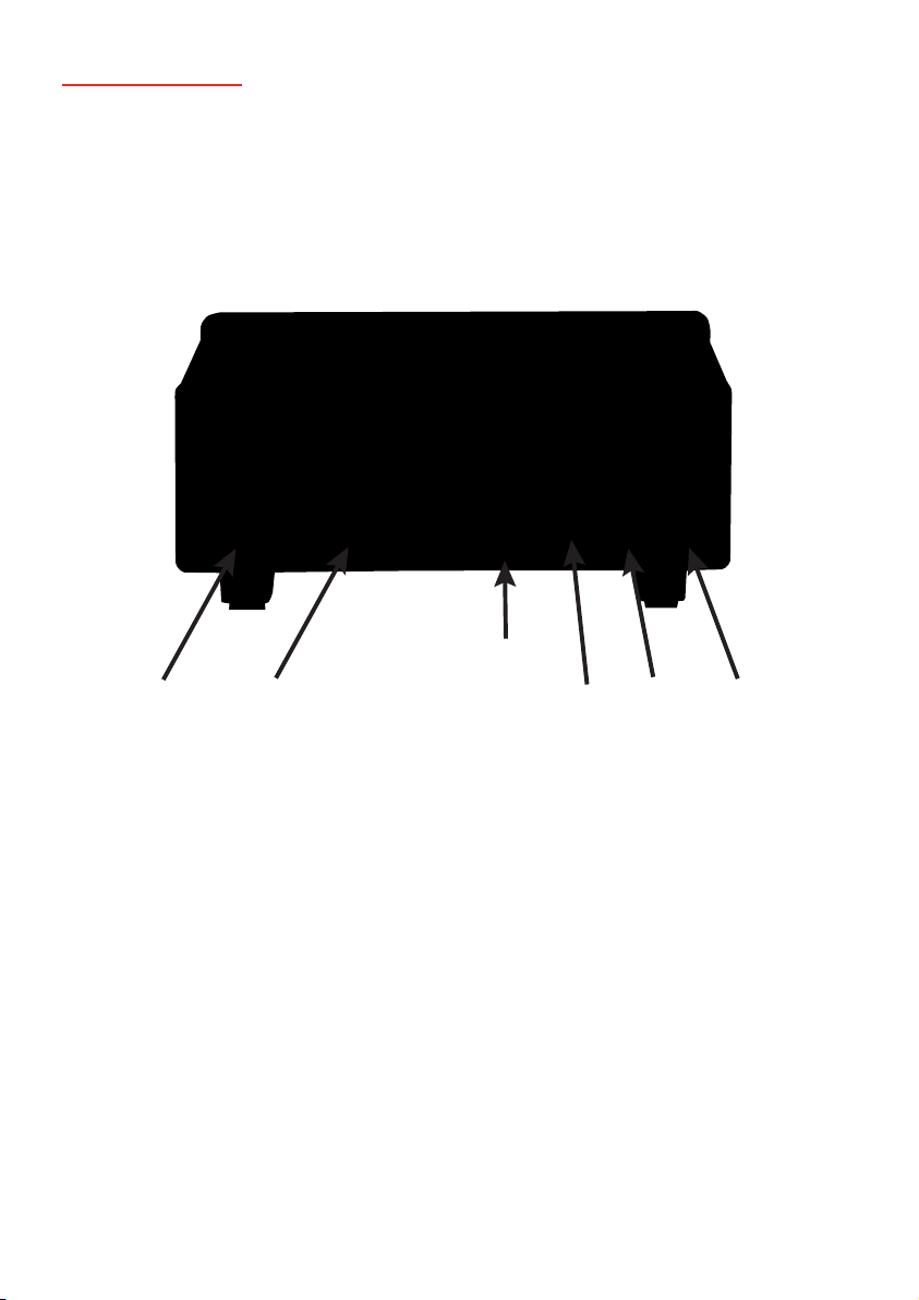
The instrument is for bench-top and portable use, folding ‘legs’ can be extended to
provide a convenient viewing angle.
All connections are made to the rear panel as indicated.
2a Supply Connection
Refer to the rear panel illustration. Primary power is provided by the internal
Lithium Ion battery which provides up to 12 hours of operation from a full
charge.The external 90 to 260V 50/60Hz power supply allows recharging and
continuous operation.The output lead with its fitted connector is plugged in to
the rear panel socket ‘DC in 5V IA’.
Pressing the front panel ‘POWER’ key switches the instrument on / off.
The battery charge indicator in the top right of the display indicates the state of
charge.The battery will charge whenever the instrument is connected to the
power adaptor.
5
DP9601 Thermometer
Analogue output
Pt100 input
Channel A
Pt100 input
Channel B
Supply
Connection
Flash
Communications
Drive
USB
Page 7
2b Communications Interface
Connect the USB cable supplied between the instrument and the PC. Refer to
the rear panel illustration.
2c Input Connection – Sensors
Refer to the rear panel illustration.
RTD sensors
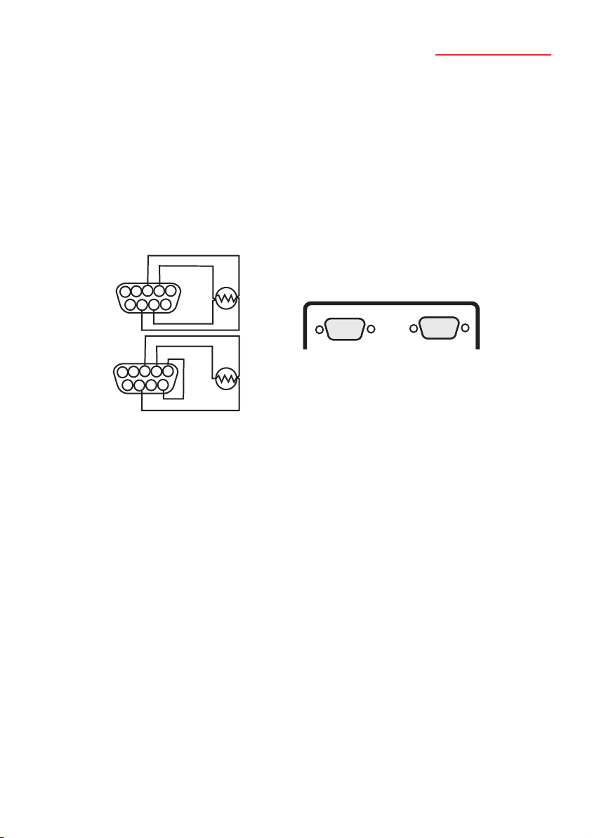
RTDs (Platinum resistance thermometers) must be fitted with a high quality
D-plug and connected to input PRT-A and/or PRT-B as required.A 3 or 4 wire
configuration can be used but they are connected differently as shown.The
instrument will automatically sense which configuration is employed.
Special care must be taken when connecting 3 wire RTD terminations
to the connector pins.A good crimp must be achieved to avoid Ohmic
contacts which would result in reading errors. Only use good quality
connectors with gold contact material; the Labfacility D type is
recommended.
Application note: Inputs are not isolated in the DP9601 which is primarily
designed for laboratory applications and site calibration of industrial temperature
sensors. Probes connected to the instrument must therefore be isolated from
high voltage pick-up.
The instrument should be disconnected from the mains adaptor and
operated from its internal batteries in such conditions.
6
DP9601 Thermometer
PRT - A
PRT - B
5
4
3 2 1
9 8 7
6
4 WIRE
V–
V+
I+
I-
5
4
3 2 1
9 8 7
6
3 WIRE
V–
V+
I+
I-
Page 8

3. Operation
Ensure that the instrument is connected to a suitable supply and that the required
connections are made.
Switch on using the ‘POWER’ key.The display will show the programme (firmware)
designation followed by a short delay while the internal checks are carried out.The
instrument will then commence normal operation according to the selected mode prior
to switch-off, e.g. if channel B, PRT was in use when switched off, this will be the mode
when switched on.
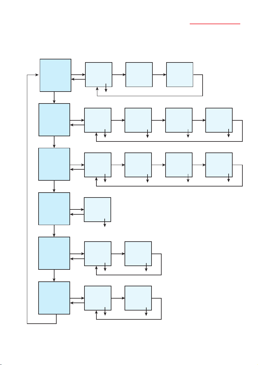
OPERATION requires the selection of appropriate menus which are shown on the
display screen. Menu screens are obtained as shown in the following sections although
the procedure is described in the text in each case.
Display brightness can be adjusted as required in the ‘SETTINGS’ sub-menu described
later.
7
DP9601 Thermometer
Page 9
8
DP9601 Thermometer
Main Menu
Correct
Main Menu
Logging
Main Menu
Settings
Main Menu
Brightness
Main Menu
D>A Setup
Enter
Escape
Enter
Escape
Enter
Escape
Enter
Escape
Enter
Escape
Pt100
Corr
View
Log
Smart
Probe
Set
Bright
D>A
Zero
Next
Corr
Next Next
Chan
Next
Write
Next Next
Log
Next
System
Next Next
D>A
Next Next
Span
Coeff
Chan
Start
Next
Log
Set
Next
Time
ENTER to edit
then
INC/DEC to change
ENTER to accept
Erase
Log
About
Next
Main Menu
A–B Null
Enter
Escape
Use Null
ENTER to
toggle on
or off
Next Next
New
Null
ENTER
Null is computed
then returns to main
menu screen
Page 10
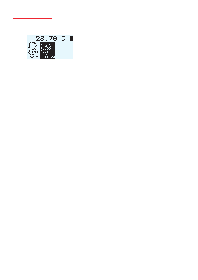
3a To read sensor temperature directly
Press ‘SENSOR’ key to select the required type of sensor if different to that
currently indicated
Brief repeated key presses will step through the various types or holding the key
depressed will auto-repeat (scroll through); this applies to other functions as well.
NOTE: If for any selected channel the sensor is either not connected
(including sensor open circuit) the display will show ‘BROKEN PROBE’.
Press ‘CHANNEL’ to select inputs A, B or A-B (differential)
Press UNITS to display the desired units °C, °F, K or Ω (dependent on the type of
sensor selected).
Press ‘RESOLUTION’ to display the desired resolution, either 0.01 or 0.001 for
°C, K and Ω only. Only 0.01 resolution can be used with °F.
3b To read differential temperature
The difference in temperature between two sensors can be obtained by displaying
channel A-B. Ensure that the required sensors are connected to the appropriate A
and B inputs.
Press ‘CHANNEL’ to select A-B after first setting up the individual channels A and
B with sensor type and corrections ON/OFF as required. Press ‘UNITS’ to display
the desired temperature units which must be appropriate to both types of sensor.
The value now displayed is the difference value between sensors A and B as
selected (i.e.A-B).
For calorimetry and certain other applications, to optimise the precision of such
differential measurements, the probe tolerances can be nulled as follows:
Nulling procedure requires the relevant probes A and B to be tagged for
repeatability. Ensure that both sensors are held at the same temperature
(say 0°C or other value) and measure A-B.
It is possible to null out differences between the two sensors measured
differentially as follows:
9
DP9601 Thermometer
Page 11
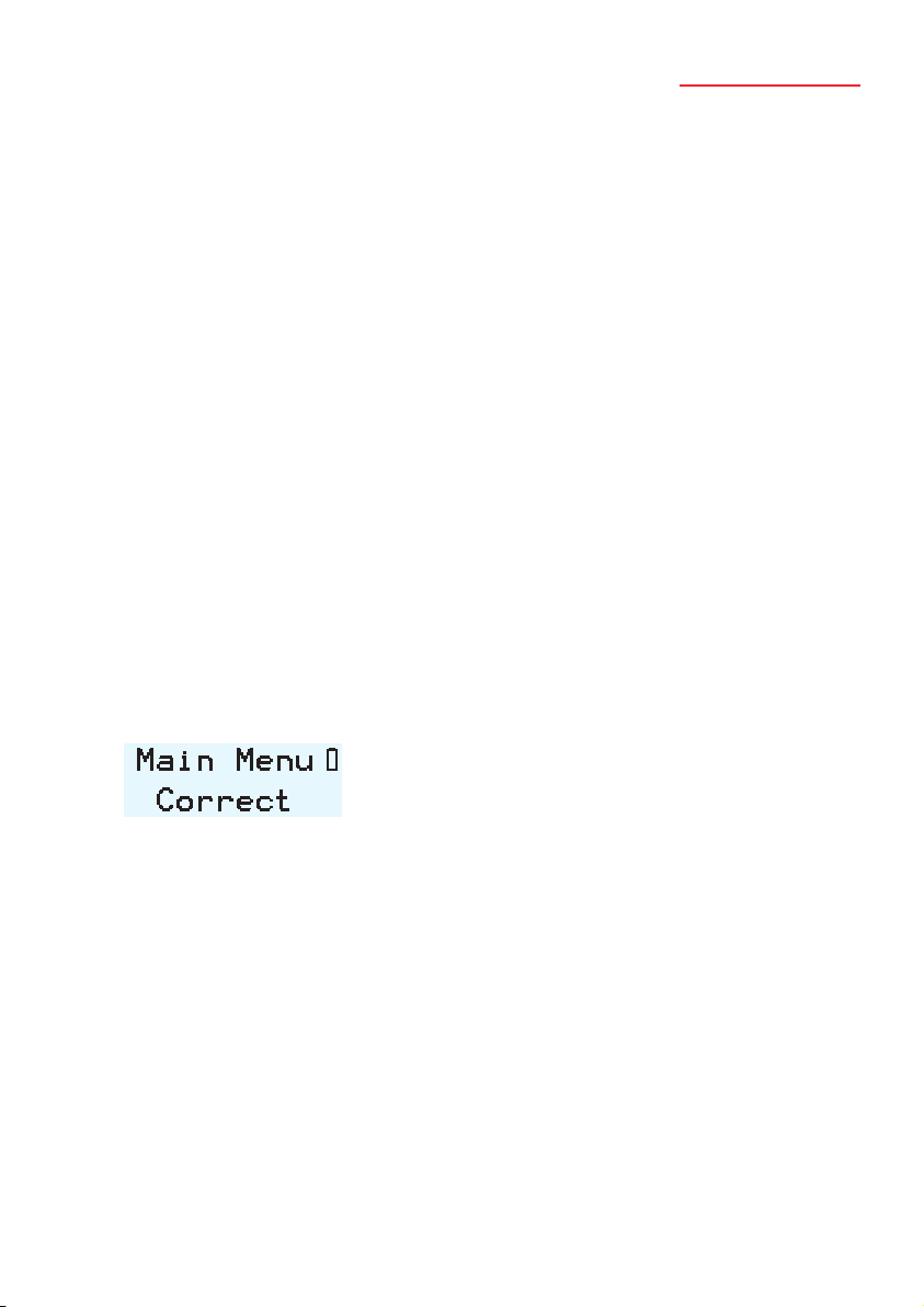
Obtain the ‘NULL’ menu A-B Null by scrolling through the sub-menus until the
menu appears. Press ‘ENTER’.
The display screen shows: =USE NULL ON/OFF & VALUE=
i) Acquiring a new null
ii) Applying a measured null value
The last null value will be applied such that the display value used is (A-B) –
(Null value).
The display screen shows: ACQUIRE NEW A-B
NULL VALUE (DEG C)
VALUE =
3c Matching DP9601 to calibrated sensors
It is possible to automatically match the DP9601 to RTD sensors with dedicated
calibration values via the PC software (see p17). Such values published in
associated certificate indicate true Ω, °C and value corresponding to accurately
known reference temperatures.
Viewing corrections via the keypad
1. Obtain the required thermocouple (TC) or Pt100 (PRT) ‘CORRECTIONS’
menu; press ‘MENU’ and then ‘CORRECT’. Press ‘ENTER’.
The display screen shows:
VIEW CORRECTIONS or VIEW CORRECTIONS
FOR THERMOCOUPLES FOR Pt100 SENSORS
10
DP9601 Thermometer
Page 12
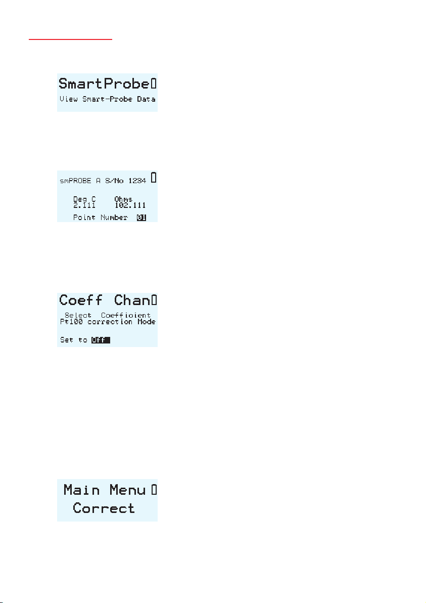
3d SMART probe operation
In the main menu, scroll down to ‘SETTINGS’ and press ‘ENTER’.The smart probe
screen is shown. Press ‘ENTER’ to view the Smart Probe data (table of values).
The probe tag and values are displayed when an appropriate probe is connected
to the instrument.
For custom coefficients
In the correction menu, scroll down to ‘COEFF’ screens and follow the prompts
to view values and to specify relevant channel (ie A / B / Both / off). Press ENTER
to select.
3e Temperature Measurement with Calibrated Sensor
To use the DP9601 with its associated calibrated sensor,ensure that;
1. The appropriate sensor(s) is/are connected to the relevant input(s) A or B.
2. Select the relevant channel to suit, ensure that the correct sensor type is
selected.
3. Then obtain ‘correct’ menu; press ‘MENU’; the ‘correct’ menu is obtained.
Scroll through options as required.
CORRECT OFF
CORRECT A
CORRECT B
CORRECT A+B
11
DP9601 Thermometer
Page 13

Press ‘ENTER” to select.
Press ‘ESCAPE’ to return to the main display which will confirm the corrections
status (CORRECT OFF OR CORRECTED).
There are eight annunciations to indicate the status of corrections when taking
readings with the DP9601:
Display screen
annunciation Status
1) OFF
2) N/A (i.e. when units are mV or Ohms)
3) OUTSIDE Tables either Local or Probe are selected but the
current electrical measurement is beyond the
electrical range defined in tables)
4) No Pts (Tables selected, but no table found)
5) Local T (Local tables i.e. in the instrument are applied)
6) Local C (Local coefficients i.e. in the instrument are applied)
7) Probe T (Probe tables i.e. in the Probe are applied)
8) Probe C (Probe coefficients i.e. in the Probe are applied)
3f Using DP9601 to obtain a secondary Calibration
There are two ways in which a non-calibrated sensor can be converted into a
secondary standard using a ‘sensor matched’ DP9601.
By means of CHANNEL A-B measurement. Connect the certified sensor to
Channel A and the un-calibrated sensor to Channel B.The sensors can be of
similar or dissimilar type, e.g. RTD certified sensor on Channel A and type K
thermocouple on T/C B.
NOTE:A-B display values at various stable, isothermal calibration
temperatures and compute sensor B corrected values accordingly.
Connect the certified sensor to Channel A and the un-calibrated sensor to
Channel B.
Compare direct A and B readings in turn at various stable, isothermal calibration
temperatures and compute sensor B corrected values accordingly. On this basis, a
range of values can be obtained for use in ‘correct B’ matching (procedure as
section 3iii)
12
DP9601 Thermometer
Page 14
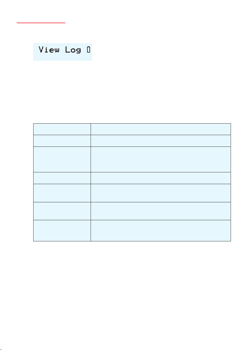
3g On-Board Logging
Select ‘LOGGING’ in the MENU. Press ‘ENTER’ to view, write, start, erase log.
Select the required memory slot (1 to 15) and enter the logging parameters.
Follow the on-screen prompts. Press ‘ESCAPE’ to exit the logging menu.
3h Error indications
The DP9601 has several modes of error indication according to internal or
external problems as follows:
DISPLAY CAUSE
BROKEN PROBE Open circuit sensor or sensor not connected to input
OUT OF RANGE Thermocouple ranges only; input mV value outside
calibration range (below min.Value or above full span
value
ILLEGAL A-B MODE A-B mode will only operate with C, F or Kelvin units
CAL LOST All calibration values corrupted or lost.
Perform re-calibration or RETURN TO FACTORY
CPU ERROR Failure of the two microprocessors to communicate.
RETURN TO FACTORY
BATTERY FLAT Inadequate battery charge to sustain operation
PLEASE RE-CHARGE within specification
Note: During normal operation, if selected probe is disconnected from
the instrument the display will indicate BROKEN PROBE. If the same
probe is re-connected, normal operation will be resumed.
13
DP9601 Thermometer
Page 15
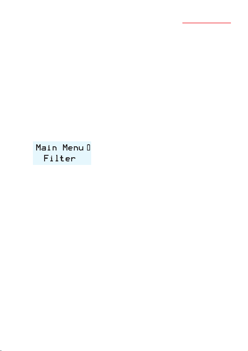
3i 3 or 4 Wire Recognition (RTD)
The DP9601 requires a minimum of 80 milliOhms lead resistance (e.g. 1 metre of
7 stranded 0.2mmΩ wire) to recognise a 4 wire probe. Otherwise the instrument
will default (perhaps correctly) to 3 wire mode.
If simulating a sensor input or calibrating the instrument, ensure 80mΩ lead
resistance between the resistance source and D plug (e.g. 1 metre of 7 x 0.2mm
Copper Cable).
3j Variable Filter Rate
In high resolution mode (RTD inputs only), the sampling rate can be varied
between 4 and 64 (i.e. the number of measurements averaged per display update).
The selection is made via the edit filter menu obtained as follows:
Press ‘MENU’ then ‘NEXT’.The edit filter menu is obtained.
The Display indicates: SELECT FILTER LENGTH 0.1 SECONDS
EACH VALUE =
Using the ‘Up/Down’ keys, enter the required value. Press ‘ENTER’ and the
resultant value will be stored until changed by the user. Press ‘ESCAPE’ to return
to the main display.
14
DP9601 Thermometer
Page 16

4. Operation with a PC
4a Install the Software
For use with a PC the software supplied with the DP9601 must be installed on
the PC and communication established (on-line green indicator showing) via the
USB lead supplied. System requirements for installing the software:Windows XP
with at least one USB port.All Windows operating systems prior to XP do not
support USB natively and are not recommended.
4b Control Panel
In the PRO Software window,double click on the ‘PRO Control Panel’ icon.The
following window is opened:
Note:When the control panel is opened subsequently, the tab selected prior to closing
will be applicable.
The on-line indicator shows ‘green’ when communications between the
instrument and the PC are established (see ‘settings’ on page 16). Local control of
the instrument is not possible (locked out) when communications between
instrument and PC are established and ‘Remote’ selected (remote control).
The front panel indicates ‘REM’.To revert to local control of the instrument (via
the front panel), click ‘LOCAL’; remote control via the PC is disabled.
15
DP9601 Thermometer
Page 17

16
DP9601 Thermometer
4c Sensor Indication
In the ‘Main’ window, the sensors for channel A and B are indicated in the relevant
boxes.
4d Settings
Click on the ‘SETTINGS’ tab for port selection if required. In many cases this may
not be required since communications may be established automatically. If not,
simply click on the appropriate port.
Page 18

4e Input Channel
Select A or B from the ‘INPUT’ box in the top centre of the control panel; the
measured value is displayed below in the ‘MEASURED VALUE’ box when
‘MEASURE NOW’ button is clicked.
4f Units and Resolution
These are selected via the appropriate boxes in the ‘Control Panel’.
4g Coefficients and Corrections
These are selected as required for each channel, their values having been set (or
default settings) via screens obtained by selecting tables ‘coefficients’ and/or ‘Tables’.
Matching to calibrated sensors (Tables Tab):
i) Select the desired input A or B in the MAIN window appropriate to the
chosen calibrated probe.
ii) Click on the ‘TABLES’ Tab
17
DP9601 Thermometer
Page 19

iii) Enter up to ten values of engineering units with 3 decimal places
(e.g. 100.100Ohms & 0.000°C) corresponding to the temperature as stated
on the calibration certificate for the ‘reference’ probe and click ‘SEND’;
this sends to table of values to the instrument. Existing values will be
overwritten.
iv) Stored ‘correction’ values can be switched ON or OFF as required in the
‘Main’ window.
v) Clicking ‘READ’ displays stored values (may be rounded up or down).
vi) Clicking ‘CLEAR’ clears values entered in the table on the window (not from
the instrument).
vii) Click ‘LOAD’ to load a corrections table from file.
viii) Click ‘SAVE’ to save the corrections table to file.
ix) Click ‘PRINT’ to print the corrections table.
4h Custom Coefficients
These can be used to effectively modify the transfer characteristic of a sensor if
required.The default coefficients are those for ITS 90; IPTS 68 was required for
example, the appropriate values could be entered.
i) The required channel,A or B as appropriate to the sensor in question must
be selected in the ‘MAIN’ window.
ii) Click on the ‘COEFFICIENTS’ tab.
iii) Enter the required values for A, B, C and Rto as appropriate and click ‘SEND’
to send these values to the instrument; existing values will be overwritten.
iv) Click ‘READ’ to see stored values at any time.
v) Click ‘LOAD’ to load a set of coefficients from file.
vi) Click ‘SAVE’ to save file.
vii) Click ‘PRINT’ to print the coefficients.
18
DP9601 Thermometer
Page 20

4i SMART Probe
Click on the ‘Probe ‘ tab to view the SMART probe window.This window is very
similar to the one in the ‘ Tables’ tab and the values stored in the probe can be
read, entered or edited.
The probe Serial No. is shown and can be modified to suit.
Click SAVE to save the values to the probe as required.
4j Log
This tab is used to control PC logging of measured values (i.e. readings are saved
to file on the PC and not on-board the instrument). Readings are saved in the
same folder as that in which the software resides.
The selected channel (as configured in the ‘Main’ tab) is indicated and the selected
sensor type. Measured value and units are also displayed. In the ‘Logging to PC’
panel, the logging interval is selected (1 to 3600 seconds). Logging commences
when ‘START’ is clicked and stopped when ‘STOP’ is clicked.
19
DP9601 Thermometer
Page 21
4k Memory
In this tab, readings stored on board the instrument can be retrieved and saved to
file (normally in the same folder which contains the PC software).
i) Click ‘READ’ to read the values.
ii) Click ‘SAVE’ to save the readings to file.
iii) Click ‘PRINT’ to print the readings.
5. Analogue (D to A) re-transmission output
In the main menu, scroll down to D>A Setup and press ‘ENTER’. Follow the on-screen
prompts to set up zero and span (degrees C) values. Press ‘ENTER’ to Edit Zero (value)
and press ‘NEXT’ to highlight the existing value; press ‘NEXT’ repeatedly to obtain the
desired value.Then press ‘ENTER’ to store the specified value. Press ‘ESCAPE’ and then
‘NEXT’; repeat the procedure for the span value.
20
DP9601 Thermometer
Page 22
6. Instrument Re-Calibration
It is recommended that this procedure is carried out by the supplier or by an
accredited laboratory facility.
Calibration must only be performed by an authorised person and in the
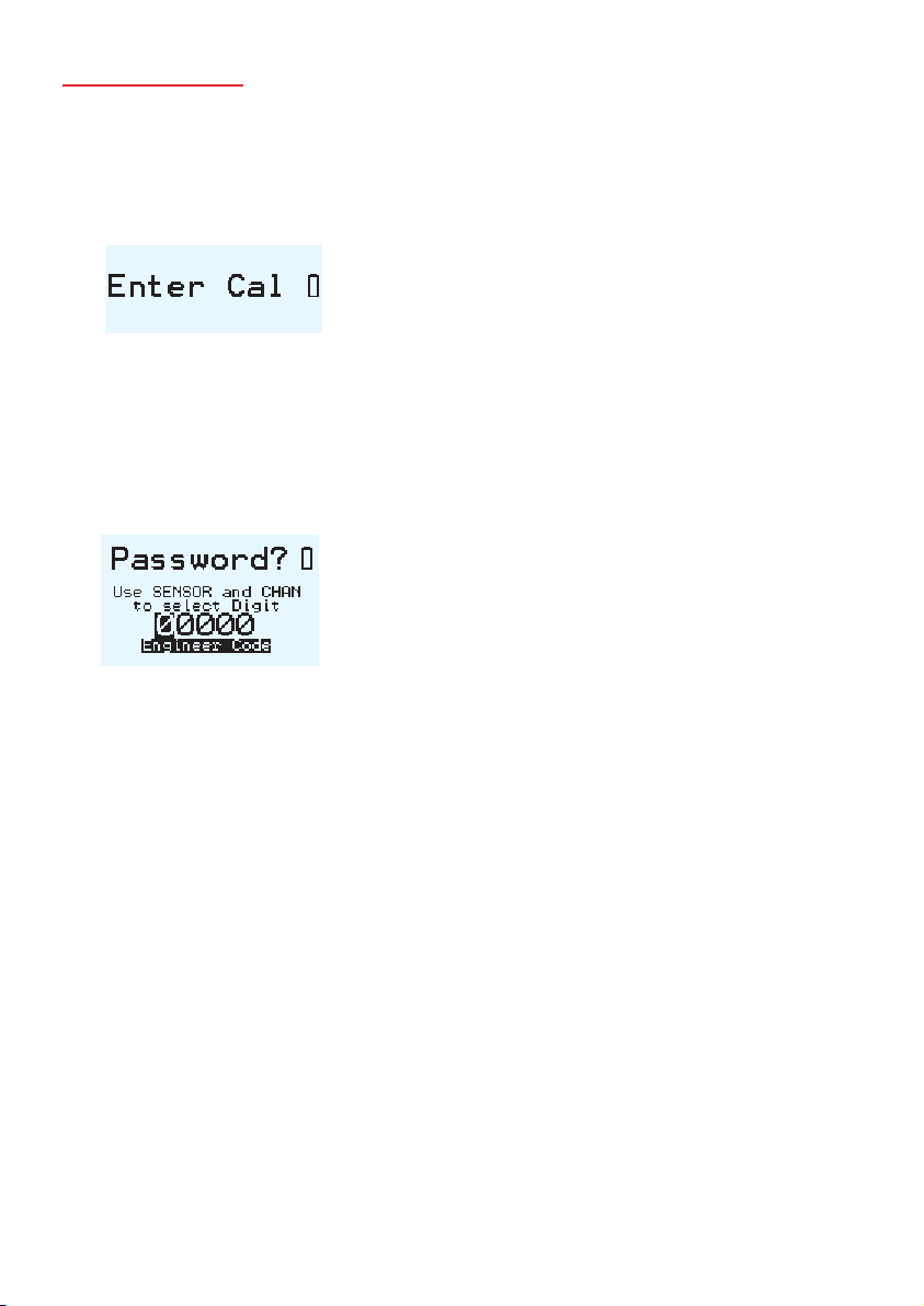
laboratory with a steady ambient temperature; access to the calibration level of
the software is via a 5 digit ‘engineer’ code; this must be entered at the prompt by
pressing ‘INC/DEC’ sequentially for the first digit.Then press ‘UNITS’ to move to the
next digit.
Re-calibration of the DP9601 is unlikely to be required routinely since its design provides
very good short and long term stability.
Item required for calibration:
i) A highly accurate resistance source providing 100.000Ω and 250.000Ω (No lead
resistance).
ii) Suitable connectors for the rear panel sockets as appropriate.
CAUTION – Do not proceed unless all specified items are available.
Failure to do so may invalidate the warranty.
21
DP9601 Thermometer
Page 23

Connect a 100 Ohm resistance to the PRT-A input port.The instrument displays the
value of the 100 Ohm input according to its previous calibration.The instrument now
measures the precise resistance and displays the value. Press ‘ENTER’ and the value is
sampled and entered. Press ‘ESCAPE’ if calibration of the channel is not required.
a) The display screen now shows; CALIBRATION
CH A PRT 100 OHMS
Connect a 250 Ohm resistance to the PRT-A port.The instrument now measures
the precise resistance and displays the value. Press ‘ENTER’ and the value is
sampled and entered.
b) The display screen now shows; CALIBRATION
CH B PRT 100 OHMS
Repeat the procedure as in c) above but using the PRT-B input port.
c) The display screen now shows; CALIBRATION
CH B PRT 250 OHMS
Repeat the procedure as in d) above but using the PRT-B input port.
22
DP9601 Thermometer
Page 24

7. Specifications
General
Inputs/Ranges/Sensors
Type RTD (Pt100) to IEC 751 (ITS 90 refers).
-200ºC to +850ºC
Ro = 100Ω
3 or 4 wire connection with automatic recognition (with
manual override)
Overall Accuracy ± 0.01ºC ± 0.0005% of span
Linearisation Conformity Better than ± 0.01ºC
Stability (vs ambient temperature)
Better than 0.0025ºC per 1ºC ambient change
Warm-up Negligible under normal ambient conditions.
Allow 5-10 minutes for full stability unless stored
at low temperature, then 30 minutes minimum.
Pt100 Sensor Current 0.5mA
Resolution of data display 0.01
Variable filter Sampling rate selectable between 4 and 64
(measurements averaged per reading).
Measurement Units °C, °F, K, Ω
Measurement Modes A, B or A-B.
Custom Calibration Up to 10 calibration values can be allocated to Pt100
input A & B and to thermocouples input A & B.Values
are retained in non-volatile memory until replaced by
user. ITS 90 or IPTS 68 coefficients can be used for
custom calibration.
Smart Sensor Connection Correction values stored in connector
Null Function Corrects differential temperature readout between two
sensors to zero.
Sensor Lead Resistance 5Ω each lead maximum
Logging 8000 readings
Supply Internal Lithium Ion rechargeable batteries.
Mains 90-260V 50/60Hz universal adaptor included.
Battery charge life up to 12 hours with full charge.
23
DP9601 Thermometer
Page 25

Series Mode Rejection 60dB @ 50Hz (50mV RMS applied)
Common Mode Rejection 30V RMS applied between input and earth produces no
measurable effect.
Display 128 x 64 pixel character OLED screen with diffused
backlighting.
Wide viewing angle, high contrast (adjustable).
Front Panel Controls 9 membrane push-keys to control all instrument
functions
Mechanical/Case Metal bench top case / adjustable tilt
Dimensions Overall 190mm(W) x 70mm(H) x 250mm(D)
Weight 3.0kg approx.
Input Connections 2 x Pt100 via D type connectors
USB Serial Isolated, 38400 Baud, 8 data, no parity, 1 stop bit.
Communications Remote control and measure.
PC Software (standard) Supplied as standard on CD-ROM. Remote control and
measure: Log readings to file/Download to
PC/Programming corrections
Analogue Output (standard) User programmable, 0 to 5V
Application Note:
Inputs are not isolated in the instrument, which is primarily designed for laboratory applications and
site calibration of industrial temperature sensors. Probes connected to the instrument must therefore
be isolated from high voltage pick-up.
24
DP9601 Thermometer
Page 26

Page 27

M-5181/0012
 Loading...