

Page 1
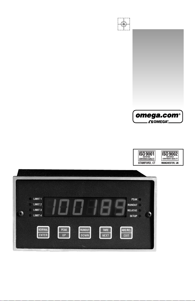
DP7700 SERIES
Dual Input Voltmeter
omega.com
e-mail: [email protected]
For latest product manuals:
omegamanual.info
User’s Guide
Shop online at
Page 2

Servicing North America:
USA: One Omega Drive, Box 4047
ISO 9001 Certified Stamford CT 06907-0047
Tel: (203) 359-1660 FAX: (203) 359-7700
e-mail: [email protected]
Canada: 976 Bergar
Laval (Quebec) H7L 5A1, Canada
Tel: (514) 856-6928 FAX: (514) 856-6886
e-mail: [email protected]
For immediate technical or application assistance:
USA and Canada: Sales Service: 1-800-826-6342 / 1-800-TC-OMEGA
®
Customer Service: 1-800-622-2378 / 1-800-622-BEST
®
Engineering Service: 1-800-872-9436 / 1-800-USA-WHEN
®
TELEX: 996404 EASYLINK: 62968934 CABLE: OMEGA
Mexico: En Espan˜ol: (001) 203-359-7803 e-mail: [email protected]
FAX: (001) 203-359-7807 [email protected]
Servicing Europe:
Benelux: Postbus 8034, 1180 LAAmstelveen, The Netherlands
Tel: +31 (0)20 3472121 FAX: +31 (0)20 6434643
Toll Free in Benelux: 0800 0993344
e-mail: [email protected]
Czech Republic: Frystatska 184, 733 01 Karvina´, Czech Republic
France: 11, rue Jacques Cartier, 78280 Guyancourt, France
Tel: +33 (0)1 61 37 2900 FAX: +33 (0)1 30 57 5427
Toll Free in France: 0800 466 342
e-mail: [email protected]
Germany/Austria: Daimlerstrasse 26, D-75392 Deckenpfronn, Germany
Tel: +49 (0)7056 9398-0 FAX: +49 (0)7056 9398-29
Toll Free in Germany: 0800 639 7678
e-mail: [email protected]
United Kingdom: One Omega Drive, River Bend Technology Centre
ISO 9002 Certified Northbank, Irlam, Manchester
M44 5BD United Kingdom
Tel: +44 (0)161 777 6611 FAX: +44 (0)161 777 6622
Toll Free in United Kingdom: 0800-488-488
e-mail: [email protected]
OMEGAnet®Online Service Internet e-mail
omega.com [email protected]
It is the policy of OMEGA Engineering, Inc. to comply with all worldwide safety and EMC/EMI
regulations that apply. OMEGA is constantly pursuing certification of its products to the European New
Approach Directives. OMEGA will add the CE mark to every appropriate device upon certification.
The information contained in this document is believed to be correct, but OMEGA accepts no liability for any
errors it contains, and reserves the right to alter specifications without notice.
WARNING: These products are not designed for use in, and should not be used for, human applications.
Page 3

TABLE OF CONTENTS
SPECIFICATIONS . . . . . . . . . . . . . . . . . . . . . . . . . . . . . . . . . . . . . . . . 1
DESCRIPTION . . . . . . . . . . . . . . . . . . . . . . . . . . . . . . . . . . . . . . . . . . . 4
SWITCH FUNCTIONS . . . . . . . . . . . . . . . . . . . . . . . . . . . . . . . . . . . . 4
LED INDICATORS . . . . . . . . . . . . . . . . . . . . . . . . . . . . . . . . . . . . . . . 5
SETUP . . . . . . . . . . . . . . . . . . . . . . . . . . . . . . . . . . . . . . . . . . . . . . . . . . 6
Limit Programming. . . . . . . . . . . . . . . . . . . . . . . . . . . . . . . . . . . . . 7
Limit One Delay . . . . . . . . . . . . . . . . . . . . . . . . . . . . . . . . . . . . . . . 7
Decimal Point Position . . . . . . . . . . . . . . . . . . . . . . . . . . . . . . . . . . 8
Filter Setup. . . . . . . . . . . . . . . . . . . . . . . . . . . . . . . . . . . . . . . . . . . . 8
Baud Rate Selection. . . . . . . . . . . . . . . . . . . . . . . . . . . . . . . . . . . . . 8
Echo Setup . . . . . . . . . . . . . . . . . . . . . . . . . . . . . . . . . . . . . . . . . . . . 8
Linefeed Setup . . . . . . . . . . . . . . . . . . . . . . . . . . . . . . . . . . . . . . . . . 8
Unit Address Setup . . . . . . . . . . . . . . . . . . . . . . . . . . . . . . . . . . . . . 8
Legend Setup . . . . . . . . . . . . . . . . . . . . . . . . . . . . . . . . . . . . . . . . . . 8
Continuous Update . . . . . . . . . . . . . . . . . . . . . . . . . . . . . . . . . . . . . 9
Device Code . . . . . . . . . . . . . . . . . . . . . . . . . . . . . . . . . . . . . . . . . . 9
Serial Command . . . . . . . . . . . . . . . . . . . . . . . . . . . . . . . . . . . . . . . 9
CALIBRATION. . . . . . . . . . . . . . . . . . . . . . . . . . . . . . . . . . . . . . . . . . . 9
Protection Code . . . . . . . . . . . . . . . . . . . . . . . . . . . . . . . . . . . . . . . 10
Protection Code Programming. . . . . . . . . . . . . . . . . . . . . . . . . . . . 10
Channel Selection Programming . . . . . . . . . . . . . . . . . . . . . . . . . . 10
Span Number Programming . . . . . . . . . . . . . . . . . . . . . . . . . . . . . 10
Dead Weight Zero . . . . . . . . . . . . . . . . . . . . . . . . . . . . . . . . . . . . . 10
Dead Weight Stay . . . . . . . . . . . . . . . . . . . . . . . . . . . . . . . . . . . . . 10
SERIAL COMMUNICATIONS . . . . . . . . . . . . . . . . . . . . . . . . . . . . . 11
Echo . . . . . . . . . . . . . . . . . . . . . . . . . . . . . . . . . . . . . . . . . . . . . . . . 12
Line Feed . . . . . . . . . . . . . . . . . . . . . . . . . . . . . . . . . . . . . . . . . . . . 13
Address Enable . . . . . . . . . . . . . . . . . . . . . . . . . . . . . . . . . . . . . . . 13
Address Disable . . . . . . . . . . . . . . . . . . . . . . . . . . . . . . . . . . . . . . . 13
Read Display . . . . . . . . . . . . . . . . . . . . . . . . . . . . . . . . . . . . . . . . . 13
Set Limit . . . . . . . . . . . . . . . . . . . . . . . . . . . . . . . . . . . . . . . . . . . . 13
Page 4

TABLE OF CONTENT
Peak and Runout . . . . . . . . . . . . . . . . . . . . . . . . . . . . . . . . . . . . . . 13
Remote Tare . . . . . . . . . . . . . . . . . . . . . . . . . . . . . . . . . . . . . . . . . . 13
Test Message . . . . . . . . . . . . . . . . . . . . . . . . . . . . . . . . . . . . . . . . . 14
Continuous Reading. . . . . . . . . . . . . . . . . . . . . . . . . . . . . . . . . . . . 14
Set Legend . . . . . . . . . . . . . . . . . . . . . . . . . . . . . . . . . . . . . . . . . . . 14
Remote Serial Command . . . . . . . . . . . . . . . . . . . . . . . . . . . . . . . . 14
Decimal Position . . . . . . . . . . . . . . . . . . . . . . . . . . . . . . . . . . . . . . 14
Reading Mode . . . . . . . . . . . . . . . . . . . . . . . . . . . . . . . . . . . . . . . . 15
Absolute or Relative . . . . . . . . . . . . . . . . . . . . . . . . . . . . . . . . . . . 15
Set Filter. . . . . . . . . . . . . . . . . . . . . . . . . . . . . . . . . . . . . . . . . . . . . 15
Calibration Span Number . . . . . . . . . . . . . . . . . . . . . . . . . . . . . . . 15
Serial Reading Mode . . . . . . . . . . . . . . . . . . . . . . . . . . . . . . . . . . . 15
Limit Mode . . . . . . . . . . . . . . . . . . . . . . . . . . . . . . . . . . . . . . . . . . 15
REMOTE INPUTS . . . . . . . . . . . . . . . . . . . . . . . . . . . . . . . . . . . . . . 16
INPUT CONNECTIONS . . . . . . . . . . . . . . . . . . . . . . . . . . . . . . . . . . 17
DP7700 BACK VIEW . . . . . . . . . . . . . . . . . . . . . . . . . . . . . . . . . . . . 17
DP7700 RANGE SETTINGS . . . . . . . . . . . . . . . . . . . . . . . . . . . . . . . 17
DP7700 REAR TERMINATIONS and HOOKUP. . . . . . . . . . . 18, 18a
18b, 18c, 18d
SCHEMATIC (DP7700 Top Board) . . . . . . . . . . . . . . . . . . . . . . . . . . 19
SCHEMATIC (DP7700 Bottom Board) . . . . . . . . . . . . . . . . . . . . . . . 22
SCHEMATIC (DP7700 Analog Input Option Board). . . . . . . . . . . . . 24
SCHEMATIC (DP7700 Output Option Board) . . . . . . . . . . . . . . . . . . 25
SCHEMATIC (DP7700 RS232/RS485 Option Board) . . . . . . . . . . . . 26
DIMENSIONS. . . . . . . . . . . . . . . . . . . . . . . . . . . . . . . . . . . . . . . . . . . 27
MOUNTING & WARRANTY . . . . . . . . . . . . . . . . . . . . . . . . . . . . . . 28
Page 5

SPECIFICATIONS
Accuracy:
• ±.01% of reading (1 counts of A/D @ 25°C. Temperature coefficient
50ppm/degree Celsius.
Display:
• -32768 to +32767 with programmable decimal points.
• .56” Red LED
NMRR:
• 70db
A/D Converter:
• 16 bits (65,536 counts) 1,000 reading per second maximum.
Input Analog Filter:
• 4 pole active anti-alias
• 500Hz cutoff on single channel unit, 250Hz cutoff on dual channel unit.
Rollover Error:
• ±50 NA maximum, (100 pA/C (per input channel)
Input Bias Current:
• ±50 NA maximum, (1200pA/C (per input channel)
Input Impedance:
• Range
Input Impedance
±200mVDC 1012Ω
±5VDC 1MΩ
±10VDC 1MΩ
4 - 20mA 10Ω
Excitation:
• ±15VDC, ±.5VDC @ 50mA
Range Selection:
• Selectable by DIP switch on rear of unit.
Calibration:
• Digital calibration via front panel switches
• No potentiometer adjustments
• Calibration switches can be disabled with access code to prevent
unauthorized access to calibration parameters.
1
Page 6

Front Panel Controls:
• Five push button switches for programming digital filter, offset, span, limits
and recall of peak reading or run out from storage.
Channels:
• One channel standard with second channel optional.
Reading Rate:
• Limited to 1000 per second divided by number of channels.
Digital Filter:
• Programmable cutoff frequency 1Hz to 500Hz.
• Display updates 3 time per second.
Peak Detector:
• Update at rate selected by digital filter. Peak is normally stored in memory
and recalled via front panel switch, over the serial interface or by selecting
peak detect display mode on rear connector. If peak display mode is selected an internal timer can be programmed to give limit #1 output up to 100
seconds after a programmed limit is reached. This output can be used to
reset the peak reading by tying limit #1 output to remote input.
Run Out Mode:
• Updated at rate selected by digital filter. Runout is normally stored in
memory and recalled via front panel switch, over the serial interface, or by
selecting runout display mode on rear connector. If runout display mode is
selected an internal timer can be programmed to give Limit #1 output up to
100 seconds after a programmed limit is reached. This output can be used to
reset the runout reading by tying Limit #1 output to remote input.
Analog Output:
• 0 - 10VDC, 0 - 5VDC, 4 - 20mA, tracks display reading.
• Voltage outputs will sink or source 1mA.
• 300V isolation between analog outputs and instrument ground
• 12 bit D/A converter updated at selected digital filter rate.
Convert/Hold Input:
• Normally high, if pulled low will hold display.
• Requires 1 millisecond positive pulse for single conversion.
Limit Outputs:
• Four isolated open collector transistor outputs rated 30VDC maximum.
• Will sink up to 50mA.
• 300V isolation between limit outputs and system ground.
• Limit #1 can be programmed to be delayed from 1 to 100 second in one second increments. Optional: Two form “A” relay contacts, rated 2.5 A @
115VAC.
2
Page 7

• Isolated transistor outputs not available when relays are installed. Limit 1
and Limit 2 activated the relay contacts.
I/O Method:
• Quick disconnect screw terminal block, RJ11 Jack for serial interface.
Power:
• 115/230VAC Selectable by switch on rear of unit.
• 8 watts maximum
• Optional 10-30VDC @ 600mA
Remote Inputs:
• Active low TTL compatible, 50 millisecond negative pulse required.
• Tare
• Display peak reading
• Display run out.
• Reset peak reading or run out reading.
Operation Temperature Range:
• -20°C to +60°C
Serial Interface:
• ASCII RS232 or RS485 compatible (optional).
• 300V isolation to system ground.
Options:
• -S2 ASCII RS232 serial interface
• -S4 ASCII RS485 serial interface
• -Dual Second input channel
• -A05 Analog output 0 - 5VDC
• -R Two relay outputs rated at 2.5A @ 115VAC, These relay outputs
take the place of the open collector outputs.
• -DC
9
/
18
9-18VDC @ 600mP
• -DC
18
/
36
18-36VDC @ 500mA
3
Page 8
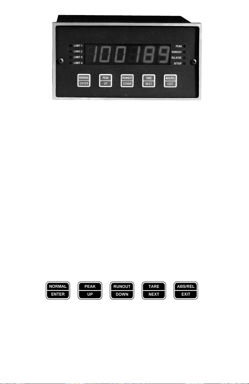
DESCRIPTION:
The Model DP7700 is a new high speed, high resolution panel meter that has the
power of a small stand alone computer. The unit can perform 1000 conversions per
second with 65000 counts of accuracy. It has an optional two channels 500 times per
second. It can detect and store a peak reading or the difference between the peak and
v
alley reading. Limits are programmable via the five front panel switches as well as the
span and gain setting. Tare (zero) of up to 50% is done via a single front panel switches
can be disabled to prevent unauthorized access and violation of calibration of unit.
SWITCH FUNCTIONS:
There are five switches located behind the front lens of the model DP7700. The front
panel switches appear as shown below. The text located at the top half of each switch
(i.e., NORMAL, PEAK, RUNOUT, TARE, ABS/REL) indicates that particular
switch’s function when the unit is in data acquisition and display mode. The text
locate
d in the lower half (i.e., ENTER, UP, DOWN, NEXT, EXIT) indicates the switch’s
function during setup and calibration. A complete description of each switch is as follows:
4
Page 9
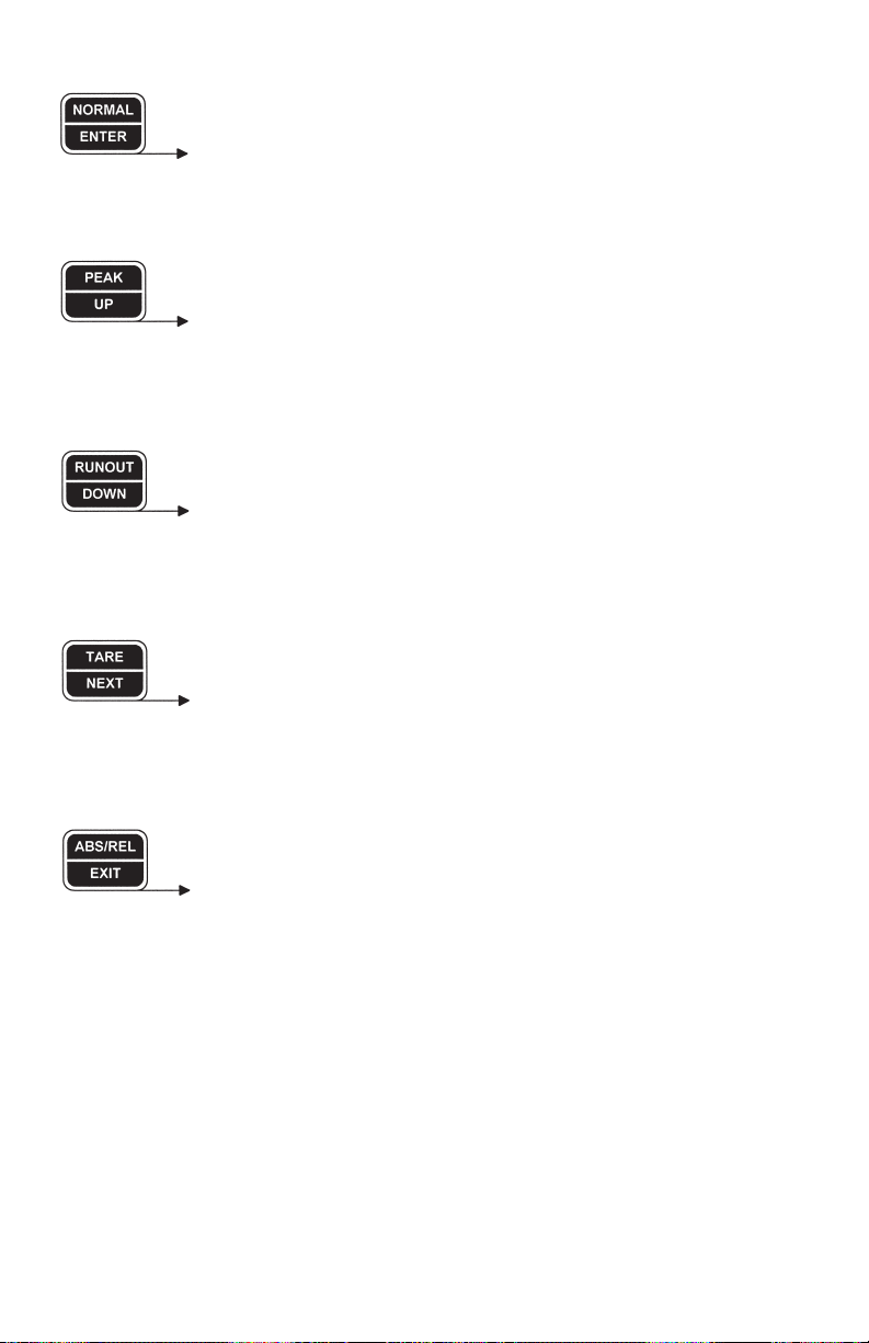
Data Acquisition & Display
: Press to set the display mode for actual reading.
Setup & Calibration Modes
: Press to record a complete setting and advance to the next setup.
Data Acquisition & Display
: Press to set the display mode for peak.
Setup & Calibration Modes
: Press to increment the digit/parameter being set.
Data Acquisition & Display
: Press to set the display mode for runout.
Setup & Calibration Modes
: Press to decrement the digit/parameter being set.
Data Acquisition & Display
: Press to record the current reading as the tare value.
Setup & Calibration Modes
: Press to advance to the next digit to be set.
Data Acquisition & Display
: Press to toggle between absolute and relative reading mode.
Setup & Calibration Modes
: Press to exit the setup or calibration mode at any time (all prior
changes are saved).
5
Page 10
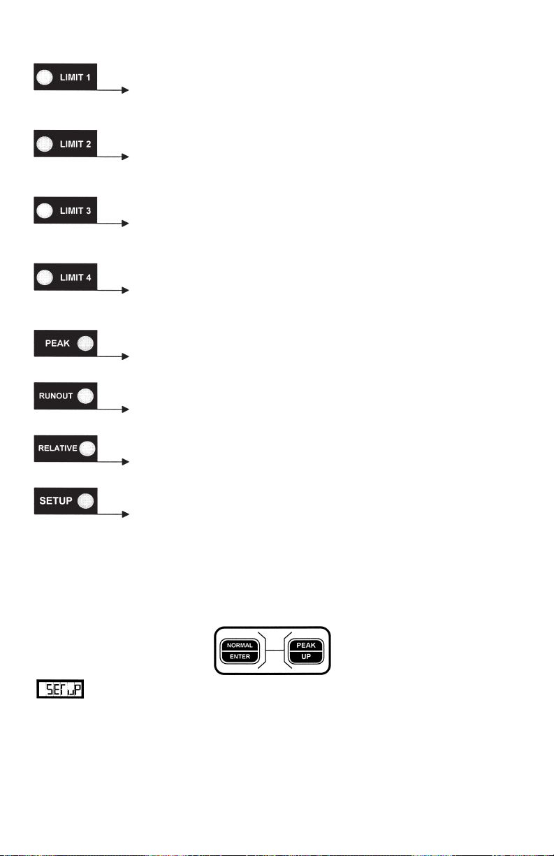
LED INDICATORS:
Limit 1 Illuminates when the display reading exceeds the set
limit, and in the setup mode when establishing the limit.
Limit 2 Illuminates when the display reading exceeds the set
limit, and in the setup mode when establishing the limit.
Limit 3 Illuminates when the display reading exceeds the set
limit, and in the setup mode when establishing the limit.
Limit 4 Illuminates when the display reading exceeds the set
limit, and in the setup mode when establishing the limit.
Peak Illuminates when the display is set in the peak mode.
Runout Illuminates when the display is set in the runout mode.
Relative Illuminates when the display is set in the relative
mode.
Setup Illuminates when the display is in the setup mode.
SETUP:
Meter setup is accomplished by using all five of the front panel switches. The setup
m
ode is entered by pressing the Normal [Enter] and Peak [Up] switches simultaneously.
will flash on the display for a second and the setup LED indicator will illuminate. While in the setup mode, programming of the meter functions is accomplished
by setting individual digits of the various parameters (with the exception of baud rate
and decimal point programming). A flashing digit indicates that it is the active digit
being set. The flashing digit can be incremented by pressing the UP switch; conversely, it can be decremented by pressing the DOWN switch. Once a particular digit has
been set to the desired value the NEXT switch can be pressed to advance to the next
6
Page 11

digit. Once all the digits have been set to the proper value the ENTER switch can be
pressed to advance to the next parameter. At any time during the setup sequence the
EXIT switch can be pressed to leave the setup mode and save the current settings. If
the setup sequence is completed the unit will save all settings and automatically return
to data acquisition and display mode. If a meter setup is started, and a long period
(approximately 100 seconds) of inactivity is detected by the meter, the meter will
return to data acquisition and display mode without saving any new settings.
Limit Programming:
All four limits are programmed in succession (1 through 4) immediately
after entering the setup mode. The corresponding LED illuminates to indicate which
limit is being programmed.
The limit number for each limit is programmed first. It can be set for any number
within the display span (as determined by the meter calibration). How the unit will use
that number for limit detection and activation is determined by the limit mode, which
is programmed following the limit number.
Will indicate that you are now programming the limit operating mode. A definition of
how the digits of the mode number affect operation of a limit follows:
1XX - Channel # 1
2XX - Channel # 2
X0X - High Limit
X1X - Low Limit
XX0 - Reading
XX1 - Peak
XX2 - Runout
Each limit (1 through 4) has it’s own limit number and limit mode to be entered.
Limit One Delay:
The limit one delay is a programmable delay, from 0 - 100 seconds,
between the time a reading exceeding the limit one number is detected and when the
limit one output will be activated. Using the delay feature, the limit one output can be
tied to the REMOTE RESET input on the rear of the unit to reset the peak reading so
that the next peak can be properly detected in a process sequence.
Decimal Point Position:
The calibration span number is displayed with the decimal point shown in
its selected position. The decimal point can be moved across the display to the desired
position using the UP and DOWN switches.
7
Page 12
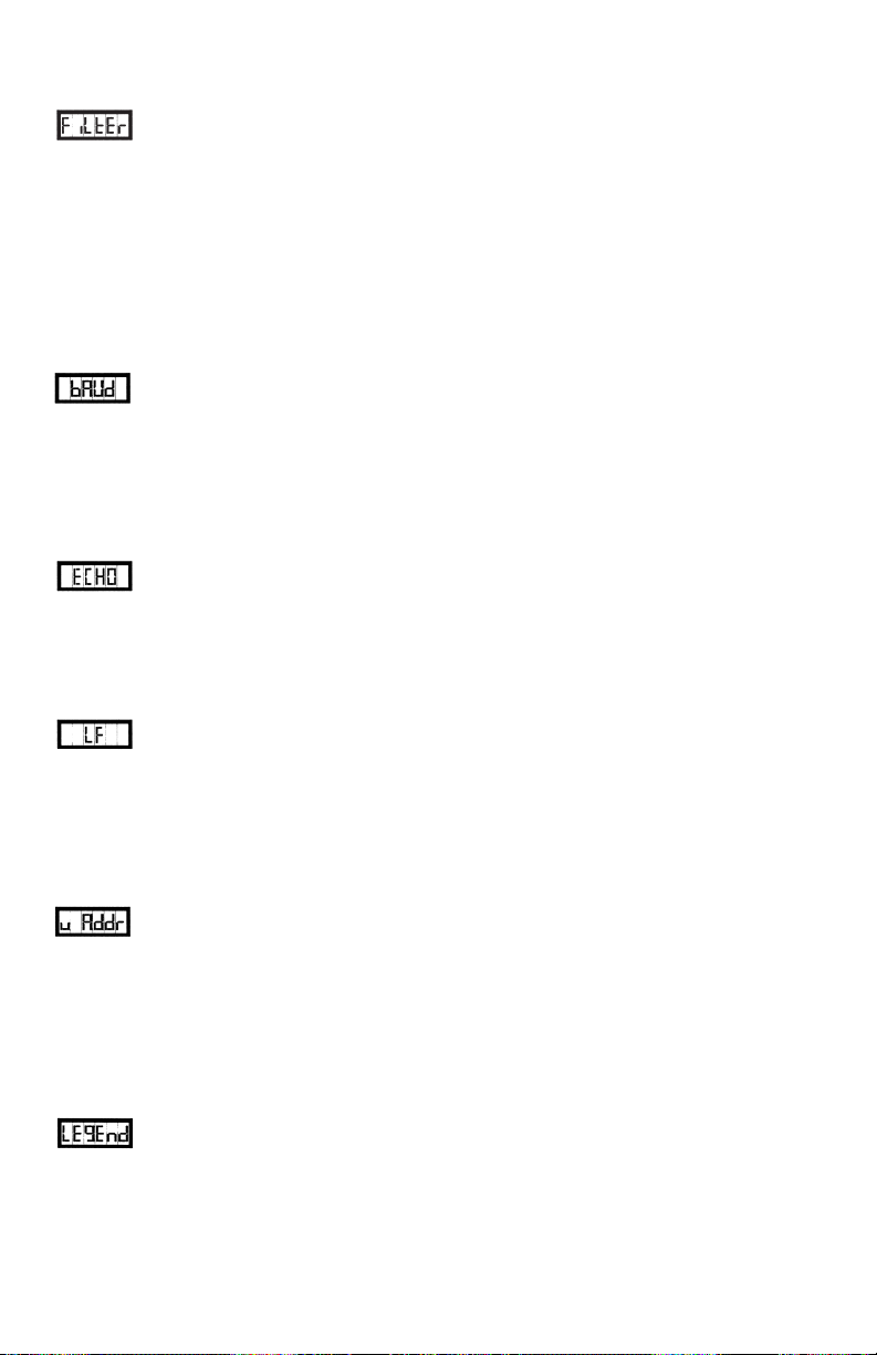
Filter Setup:
The digital filter determines the rate at which the limits are checked for output activation, peak/runout tracking, and analog output updates. The digital filter is
programmable from 1 to 500Hz. When stability is more an issue than speed the filter
should be set closer to 1Hz; conversely, when quick detection and activation is more
important the filter should be set closer to 500Hz. Note: Unless the serial option is
installed, the setup sequence is now finished and the unit will return to acquisition and
display mode.
Baud Rate Selection:
Program the desired baud rate using the UP or DOWN switches to toggle
through the available settings (300, 600, 1200, 2400, 4800, 9600, 19200, and 38400).
Once the proper baud rate is selected press the ENTER switch to advance to the next
setup.
Echo Setup:
The model DP7700 can be programmed to automatically re-transmit (echo)
characters received on its serial communications input. A value of one enables the
echo feature; conversely, programming a zero will disable it.
Linefeed Setup:
The unit can be programmed to transmit linefeed characters in addition to
the carriage return that is transmitted at the end of data strings. Programming a one
will enable transmission of linefeed characters, while programming a zero will prevent
their transmission.
Unit Address Setup:
Multiple DP7700 units can be networked together on a serial bus using the
addressing capability of the unit. Each unit can have a unique address from 0 to 250
(Note: 0 disables the address feature since the unit will respond to all incoming commands/queries).
Legend Setup:
The DP7700 can append a user selectable engineering units string to readings transmitted from the unit. This feature allows direct terminal readout in engineering units, or easier unit identification in multi-unit applications. Program the legend
number to the number corresponding with desired units as shown in the following
table.
8
Page 13
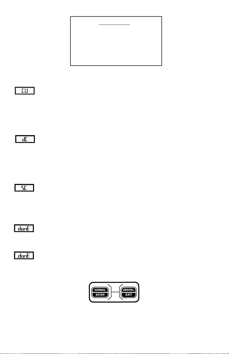
Legend Table
0 - No Legend 4 - kpa.
1 - lbs. 5 - mV.
2 - kgs. 6 - mA.
3 - psi. 7 - V.
Continuous Update:
The model DP7700 can be programmed to automatically transmit the display reading at selectable time intervals. The update interval can be programmed from
20 times per second (-1) up to a maximum of 3600 seconds (3600). A value of zero
disables the automatic update function.
Device Code:
A non-printable device code allows units to take turns on a serial bus when
daisy chained to a printer or some other data recording device. A value of one enables
transmission of the device code following the reading string; conversely, a value of
zero disables transmission of the device code.
Serial Command:
A serial command can automatically be executed upon receipt of a nonprintable code (see device code above). A table of numbers associated with each serial
command can be found in the serial communications section of the manual (on page
8). Program to the number associated with the command to be executed when the unit
receives a device code character on its serial communications input.
CALIBRATION:
The calibration mode is entered by pressing the Normal [Enter] and
ABS/REL [Exit] switches simultaneously. Note: This is the only method to check or
change the calibration of this unit externally.
9
Page 14
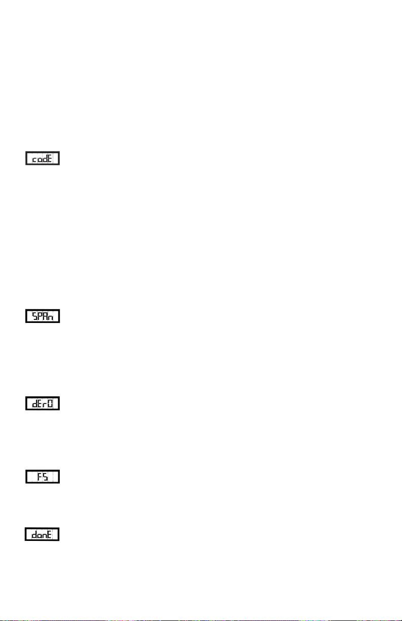
Protection Code:
Before any calibration can be performed on the unit a unique security code must be
entered. If the code is not entered correctly the unit will automatically revert to display and acquisition mode; otherwise, the user is allowed to proceed with the calibration sequence. To enter the code use the Peak[Up] or the Runout[Down] switches to
enter the code any were from 0 - 255. The unit is shipped from the factory with a programmed code of 10.
Protection Code Programming:
A different protection code can be programmed at this time. The code can
be anywhere in the range 0 - 255. If a new code is not required simply press ENTER to
continue with the calibration sequence.
Channel Selection Programming:
The display will now show one (1) to indicate that the calibration is to be performed
on channel #1 as the default. If channel number two calibration is required, select
number two (2). To select the channel number use the Peak[Up] or Runout[down]
switch to toggle the number. Press enter to continue with calibration.
Span Number Programming:
The span number is the display reading that is associated with the input
obtained during the DEAD WEIGHT STAY portion of the calibration sequence. The
span number can be programmed to a maximum of 32767 display counts.
Dead Weight Zero:
This is the zero (null) point calibration step. Set the transducer or calibrator
for zero output, allow sufficient time for the reading to stabilize, then press the
ENTER switch to store the new zero calibration data.
Dead Weight Stay:
This is the span point calibration step. Check to make sure that the span
setting is selected to match the desired input range. Set the transducer or calibrator for
full-scale output, allow sufficient time for the reading to stabilize, then press the
ENTER switch to store the new span calibration data.
10
Page 15

SERIAL COMMUNICATIONS:
With the serial communications option installed, the model DP7700 can easily be
interfaced to a computer, terminal, or printer. The unit can operate in stand-alone mode
or in networked applications. Both RS232 and RS485 serial communication options
are available, for the DP7700. The baud rate is user selectable, and can range from 300
to 38.4K baud. The unit uses a N,8,1 character data format (no parity, 8 data bits, 1
stop bit). All data is transmitted/received as ASCII characters. Characters strings are
transmitted/received with the leftmost character first and are terminated with a carriage
return [CR]. Incoming linefeeds are ignored by the unit, and it is optional to have the
unit transmit them. Leading zeros are acceptable for numeric data transmitted to the
unit. Decimal points are ignored by the unit, and are transmitted, when required, to
conform with the selected display format.
Listed below are the available commands for the model DP7700 (with the associated
command numbers). Following this is a discussion of how commands are interpreted
by the unit along with a brief description for each command.
1 EH Set Echo Mode
2 LF Set Line Feed Mode
3 AE Address Enable
4 AD Address Disable
5 RD Read Display
6 NOT USED
7 NOT USED
8 S1 Set Limit One
9 S2 Set Limit Two
10 S3 Set Limit Three
11 S4 Set Limit Four
12 SP Peak and Runout
13 NOT USED
14 SZ Remote Tare
15 NOT USED
16 NOT USED
17 NOT USED
18 NOT USED
19 TM Test Message
20 NOT USED
21 NOT USED
22 CR Set Continuous Reading Mode
23 NOT USED
24 NOT USED
25 NOT USED
26 LR Set Legend
27 SC Remote Serial Command
28 DP Set Decimal Point Position
29 NOT USED
34 NOT USED
35 PV Set Display Mode
36 AR Absolute or Relative
37 SF Program Filter
38 SN Calibration Span Number
39 NOT USED
40 NOT USED
41 SM Serial Read Mode
42 LM Limit Mode
11
Page 16

Each DP7700 command consists of two upper-case alpha ASCII characters. In most
instances, commands can be sent to the unit with a numeric value (ASCII format)
attached for parameter setting. When the unit receives and executes a valid command
it responds by transmitting “ok[CR]”. Commands can also be sent to the unit without
a parameter attached to interegate the current setting for the parameter associated with
that command. In this instance, the unit responds with the equivalent lower-case characters for that particular command along with an ASCII representation for the numeric
value of the parameter in question. The following is an example of a possible
exchange sequence between a model DP7700 and a host computer:
Exchange 1: HOST SENDS : “AE0[CR]”
DP7700 RESPONDS WITH : “HELLO ae 0[CR]”
(Note: The unit address is assumed to be set at zero.)
Exchange 2: HOST SENDS : “RD[CR]”
DP7700 RESPONDS WITH : “99.99lbs[CR]”
(Note: It is assumed the display reading is 99.99 and that the legend is set for lbs.)
Exchange 3 HOST SENDS : “S1 1000[CR]”
DP7700 RESPONDS WITH : “ok[CR]”
Exchange 4 HOST SENDS : “S1[CR]”
DP7700 RESPONDS WITH : “11 1000[CR]”
Exchange 5 HOST SENDS : “AD0[CR]”
DP7700 RESPONDS WITH : “BYE ad 0[CR]”
Note: Remember [CR] represents a carriage return character.
The following is a list of the serial commands available on the DP7700. Each command string is shown in quotes, a parameter/number field is represented by X (first) or
Y (second), the sign, where needed, is shown as a lower case s(s). A brief description is
given for each command along with any particular programming instructions.
ECHO: “EH X[CR]”
The echo command allows enabling or disabling of the unit’s echo feature. When the
echo feature is turned on the unit automatically echo’s all received characters.
X = 1 echo ON
X = 0 echo OFF
12
Page 17

LINE FEED: “LF X[CR]”
The unit can be set to send a line feed character following each transmitted string.
X = 1 line feeds are transmitted.
X = 0 line feeds are not transmitted
ADDRESS ENABLE: “AE XXX[CR]”
The address enable command, in conjunction with the address disable command, can
be used to network multiple DP7700 units. Once a unit’s address has been enabled it
will respond to all incoming commands until the unit’s address is disabled. When the
address enabled command is executed by a DP7700 it responds with “HELLO an
XXX[CR].” Note: a unit address of zero (0) disables the addressing feature and the
address enable command is not required.
ADDRESS DISABLE: “AD XXX[CR]”, or “AD[CR]”
This command disables the unit at the specified address, or when an address in not
attached, all units on the network. When the command is successfully executed, the
unit will respond with “BYE ad XXX[CR]”.
READ DISPLAY: “RD[C.R.]”
Requests transmission of the current DP7700 display reading. The type of reading
returned (i.e. peak, runout, or current input) will depend upon the display reading
mode selected. The unit will format the reading with sign and decimal point as needed.
SET LIMIT: “S# XXXXX[CR]”
Allows remote setting of the DP7700 limit numbers. The # should be replaced in the
string with the number of the limit to be set (1 through 4).
PEAK AND RUNOUT: “SP[CR]”
When this command is received the peak and runout reading are then reset.
REMOTE TARE: “SZ X[CR]”
The remote tare command allows tare “capture” similar to that performed by the front
panel TARE switch. When a number is attached to the command a new tare value is
captured.
13
Page 18

TEST MESSAGE: “TM[CR]”
The test message is primarily a diagnostic aid. When the test message command is
received the unit will respond by outputting information particular to the model number and software version/revision.
CONTINUOUS READING: “CR XXXX[CR]”
The continuous reading command allows setting of the automatic update feature of the
DP7700.
X = -1 - readings are transmitted 20 times per second
X = 0 - automatic updates disabled
XXXX = 1 - 3600 -number of seconds between updates
SET LEGEND: “LR X[CR]”
The set legend command allows a unit indicator to be attached to readings transmitted
by the unit.
X = ? legend number (from the table on page 9) for reading units.
REMOTE SERIAL COMMAND: “SC X YY[CR]”
In data logging applications, involving several units daisy-chained together, a problem
arises when it is desired to have several units automatically transmit readings at the
same time interval (since contention could result in scrambled data at the printer). To
compensate for this, the model DP7700 allows unit to “take turns” on the same serial
bus. This is done by enabling transmission of a special non-printable character at the
end of a reading string; which, when received by the following unit will cause it to
execute a serial command (RD would be most common). The second unit can have
the device code enabled and so on. Note: all units should have the echo function
enable so that messages will pass along to the following units in the chain.
DECIMAL POSITION: “DP X[CR]”
The display decimal point can be positioned using this command.
X = 0 88888 (no decimal point)
X = 1 8888.8
X = 2 888.88
X = 3 88.888
X = 4 8.8888
X = 5 .88888
14
Page 19

READING MODE: “PV X[CR]”
The display reading mode can be set using this command.
X = 0: Display is set for reading only
X = 1: Display is set for peak
X = 2: Display is set for runout
ABSOLUTE OR RELATIVE “AR X[CR]”
Allows changing of the display mode between absolute and relative.
X = 0 Absolute measurement only (tare is disabled)
X = 1 Relative measurement (tare enabled)
SET FILTER “SF XXX[CR]”
The set filter command can be used to remotely set the rate at which limit detection,
peak/runout tracking, and analog output updates are performed.
XXX = 1 - 500 (Hz)
CALIBRATION SPAN NUMBER “SN X YYYY[CR]”
X = Channel number (1 or 2)
YYYY = Calibration span number
SERIAL READING MODE “SM X[CR]”
X = 0 : Serial read outputs channel #1 (display reading)
X = 1 : Serial read outputs channel #2 reading
X = 2 : Serial read outputs channel #2 peak
X = 3 : Serial read outputs channel #2 runout
LIMIT MODE “LM X N[CR]”
X = Limit number
N = Limit mode, bit defined as follows:
Normal - 01 HEX
Peak - 02 HEX
Runout - 03 HEX
Channel #2 - 04 HEX
High limit - 08 HEX
15
Page 20

Example: Assume we want a high limit, normal (reading), active on channel one; then,
YY = 01 OR’ed 08 = 09 HEX (NOTE: unlike most serial command parameters, this
is not ASCII).
REMOTE INPUTS:
Seven logic level, active-low, remote inputs are located on the rear of the unit for interfacing to programmable logic controllers etc.. The remote inputs can be used to duplicate many of the front panel switch functions of the unit. A brief description of each
input follows below:
NORMAL MODE (remote input #1) - sets the display mode to reading only.
DATA REQUEST (remote input #2) - requests a serial transmission of the
display reading
RESET P/R (remote input #3) - resets the peak and runout readings
DATA HOLD (remote input #4) - A/D samples are ignored while this
input is active
RUNOUT MODE (remote input #5) - sets the display mode to runout
PEAK MODE (remote input #6) - sets the display mode to peak
CAPTURE TARE (remote input #7) - sets the tare value to the current display
reading
All remote inputs must be active for a minimum of 50mS (with the exception of DATA
HOLD which only needs to be held active a minimum of 1mS for detection).
16
Page 21
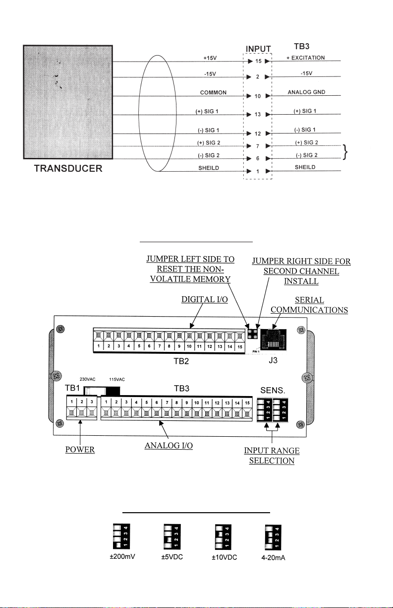
INPUT CONNECTIONS - TRANSDUCER TO TB3
USING INTERNAL ±15VDC SUPPLY
DP7700 BACK VIEW
DP7700 RANGE SETTINGS
17
Dual
Option
Only
NOTE: ONLY ONE RANGE SELECTOR SWITCH WOULD BE
INSTALLED UNLESS DUAL OPTION IS ORDERED.
Page 22

DP7700 REAR TERMINATIONS
TB1 (POWER INPUT - BOTTOM BOARD)
(1) AC LINE
(2) AC NEUTRAL
(3) EARTH GROUND
TB2 (TOP BOARD) TB3 (BOTTOM BOARD)
(1) LIMIT 1 (1) SHIELD
(2) LIMIT 2 (2) -15V
(3) LIMIT 3 (3) ANALOG OUTPUT
(4) LIMIT 4 (4) N/C
(5) NORMAL MODE (5) N/C
(6) DATA REQUEST (6) -SIGNAL2
(7) RESET P/R (7) +SIGNAL2
(8) DATA HOLD (8) N/C
(9) RUNOUT MODE (9) N/C
(10) PEAK MODE (10) COMMON
(11) CAPTURE TARE (11) N/C
(12) +5V (12) -SIGNAL1
(13) ISOLATED POWER (13) +SIGNAL1
(14) ISOLATED GROUND (14) N/C
(15) INSTRUMENT GROUND (15) +15VDC
J3 (RJ11 - TOP BOARD)
(1) RS485 SERIAL
(2) RS485 TERMINATION RESISTOR
(3) RS232 RX
(4) RS232 TX
(5) RS232 - GROUND
(6) RS485 ~SERIAL
18
Page 23
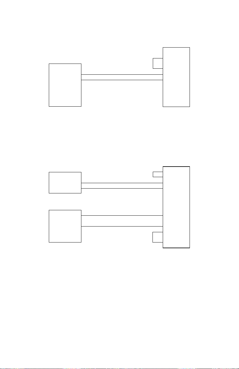
12
10
15
13
7
15
6
10
4 - 20 mA TWO WIRE HOOKUP
SINGLE CHANNEL
12
10
15
13
TRANSDUCER
with 4 - 20 mA
OUTPUT
+ 15VDC
+ 4 - 20 mA
DUAL CHANNEL
TRANSDUCER
with 4 - 20 mA
OUTPUT
TRANSDUCER
with 4 - 20 mA
OUTPUT
+ 15VDC
+ 4 - 20 mA
+ 4 - 20 mA
+ 15VDC
18 A
Note: (+) (-) signal input level is selectable by switch(s) on rear of unit.
Input range 0 to +20mVDC, +5VDC, +10VDC, and 4-20 mA.
Page 24
19
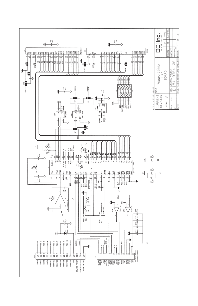
SCHEMATIC (DP-7700 Top Board)
Page 25
20
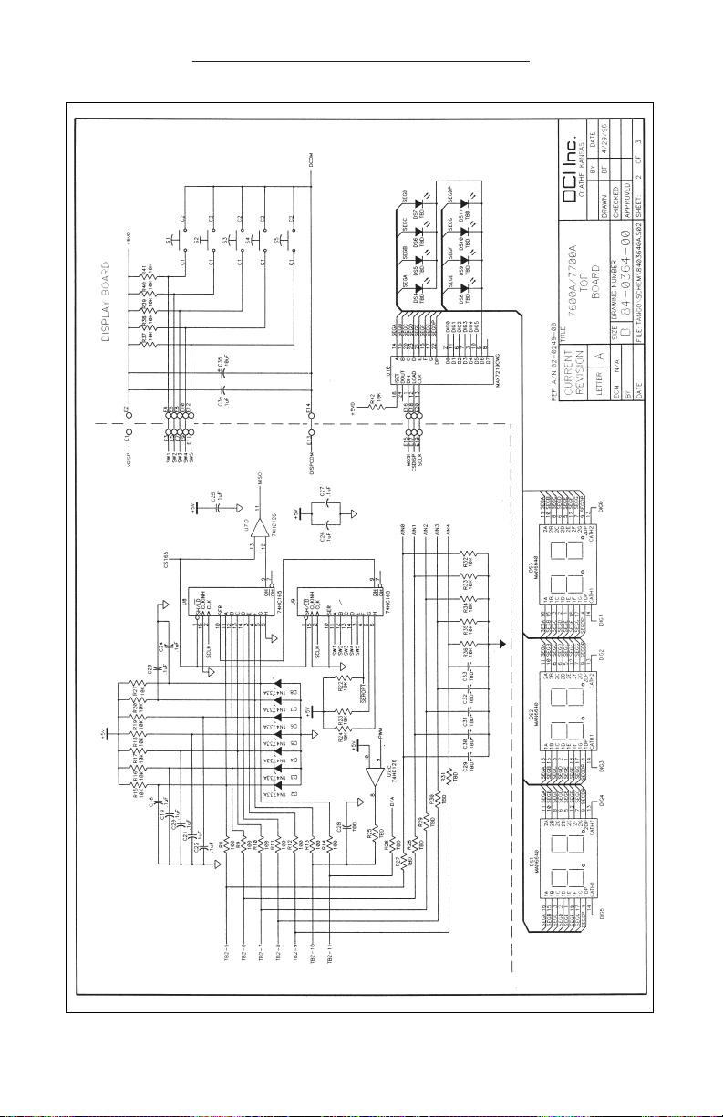
SCHEMATIC (DP-7700 Top Board)
Page 26
21
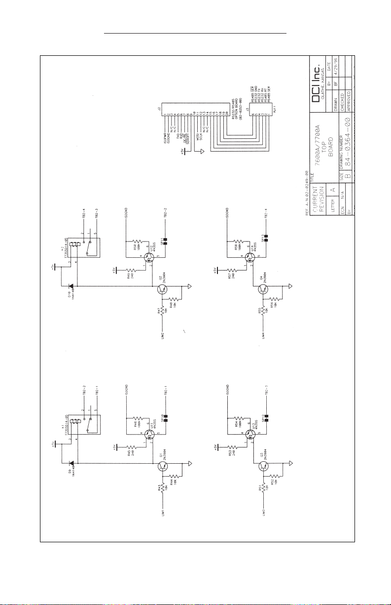
SCHEMATIC (DP-7700 Top Board)
Page 27
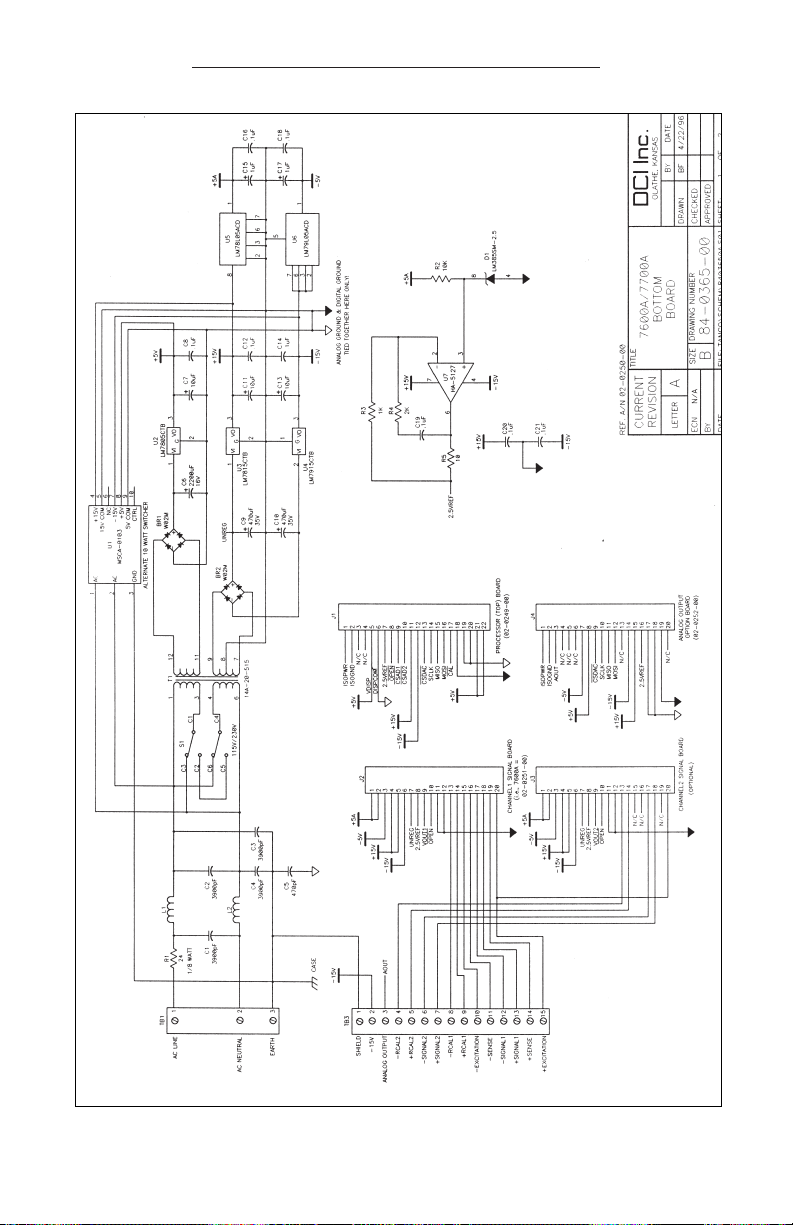
22
SCHEMATIC (DP-7700 Bottom Board)
Page 28

23
SCHEMATIC (DP-7700 Bottom Board)
Page 29
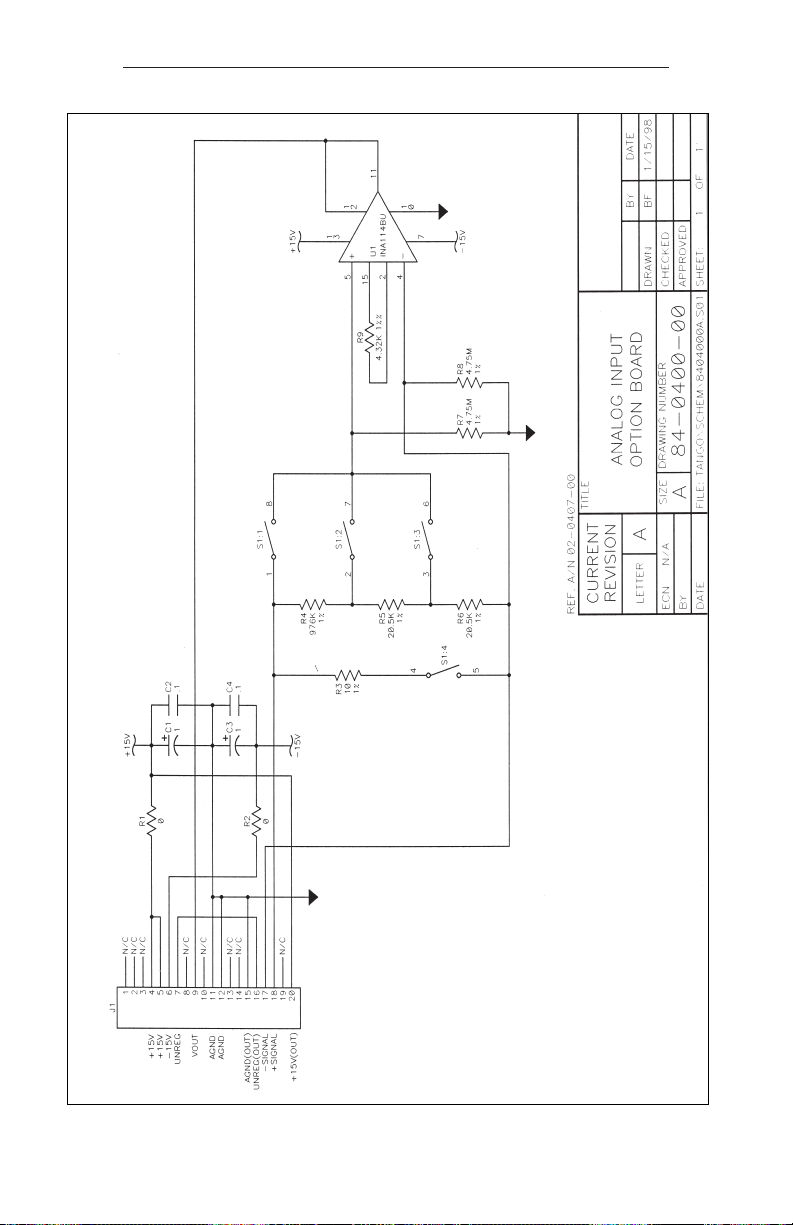
24
SCHEMATIC (DP-7700 Analog Input Option Board)
Page 30
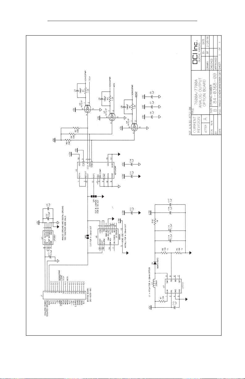
SCHEMATIC (DP-7700 Output Option Board)
25
Page 31
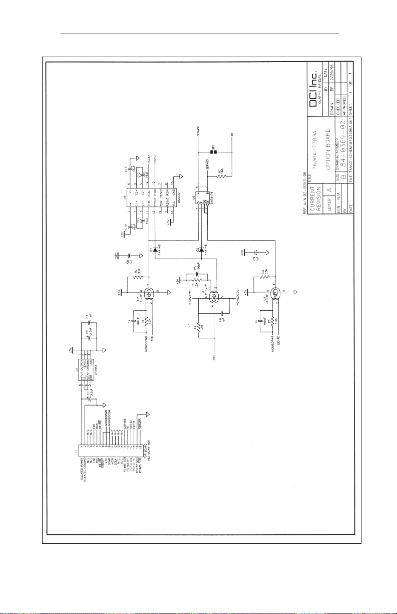
SCHEMATIC (DP-7700 RS232/RS485 Option Board)
26
Page 32
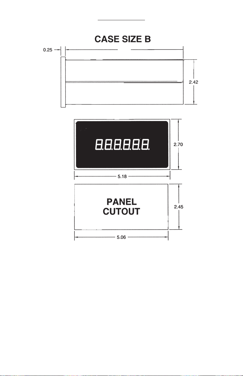
DIMENSIONS
27
6”
INCLUDING I/O CONNECTOR
Page 33
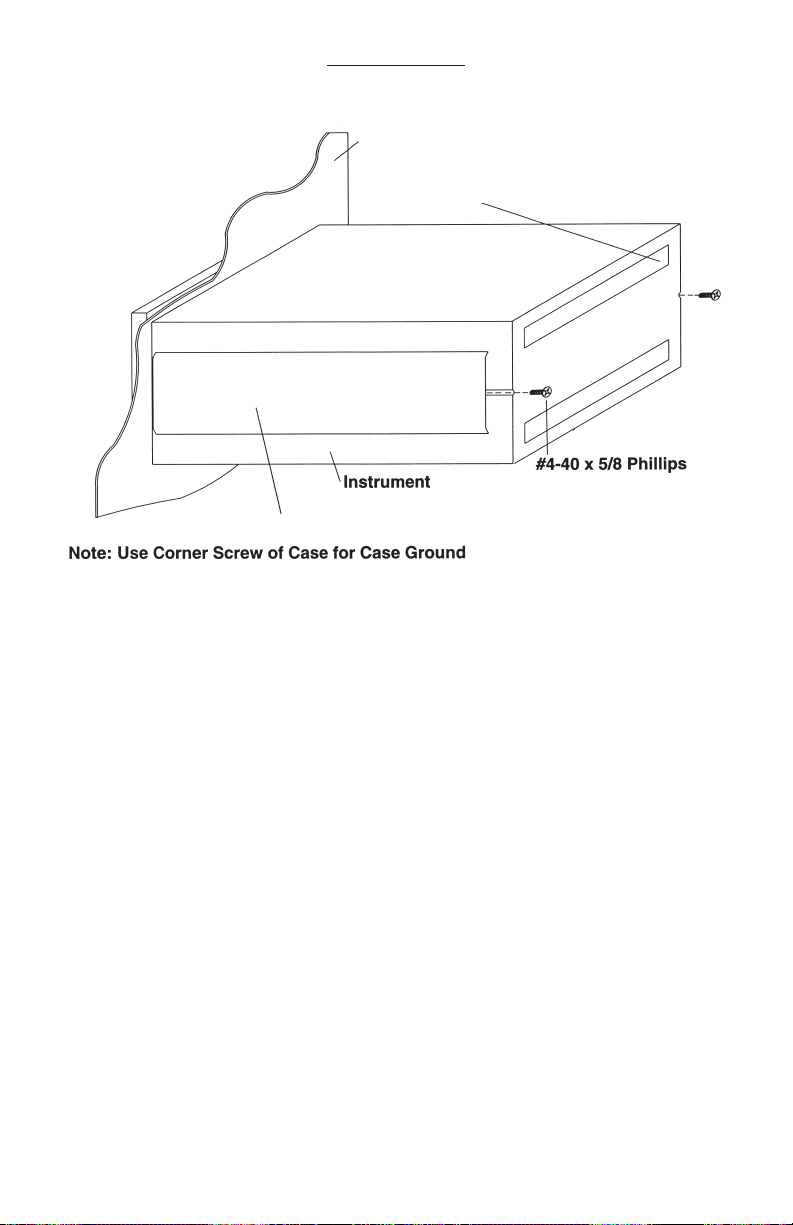
MOUNTING
Customers Panel with Cutout
to mount Omega Instrument
I/O Connectors Supplied by
Omega Number and Style Vary
Mounting Straps Supplied by Omega
28
Page 34

NOTES:
29
Page 35

WARRANTY/ DISCLAIMER
OMEGA ENGINEERING, INC. warrants this unit to be free of defects in materials and
workmanship for a period of 13 months from date of purchase. OMEGA’s WARRANTY adds an
additional one (1) month grace period to the normal one (1) year product warranty to cover
handling and shipping time. This ensures that OMEGA’s customers receive maximum
coverage on each product.
If the unit malfunctions, it must be returned to the factory for evaluation. OMEGA’s Customer
Service Department will issue an Authorized Return (AR) number immediately upon phone or
written request. Upon examination by OMEGA, if the unit is found to be defective, it will be
repaired or replaced at no charge. OMEGA’s WARRANTY does not apply to defects resulting
from any action of the purchaser, including but not limited to mishandling, improper interfacing,
operation outside of design limits, improper repair, or unauthorized modification. This
WARRANTY is VOID if the unit shows evidence of having been tampered with or shows evidence
of having been damaged as a result of excessive corrosion; or current, heat, moisture or vibration; improper specification; misapplication; misuse or other operating conditions outside of
OMEGA’s control. Components which wear are not warranted, including but not limited to
contact points, fuses, and triacs.
OMEGA is pleased to offer suggestions on the use of its various products. However,
OMEGA neither assumes responsibility for any omissions or errors nor assumes liability
for any damages that result from the use of its products in accordance with information
provided by OMEGA, either verbal or written. OMEGA warrants only that the parts
manufactured by the company will be as specified and free of defects. OMEGA MAKES
NO OTHER WARRANTIES OR REPRESENTATIONS OF ANY KIND WHATSOEVER,
EXPRESSED OR IMPLIED, EXCEPT THAT OF TITLE, AND ALL IMPLIED WARRANTIES
INCLUDING ANY WARRANTY OF MERCHANTABILITY AND FITNESS FOR A PARTICULAR
PURPOSE ARE HEREBY DISCLAIMED. LIMITATION OF LIABILITY: The remedies of purchaser set forth herein are exclusive, and the total liability of OMEGA with respect to this
order, whether based on contract, warranty, negligence, indemnification, strict liability or
otherwise, shall not exceed the purchase price of the component upon which liability is
based. In no event shall OMEGA be liable for consequential, incidental or special damages.
CONDITIONS: Equipment sold by OMEGA is not intended to be used, nor shall it be used: (1) as
a “Basic Component” under 10 CFR 21 (NRC), used in or with any nuclear installation or activity;
or (2) in medical applications or used on humans. Should any Product(s) be used in or with any
nuclear installation or activity, medical application, used on humans, or misused in any way,
OMEGA assumes no responsibility as set forth in our basic WARRANTY/ DISCLAIMER language,
and, additionally, purchaser will indemnify OMEGA and hold OMEGA harmless from any liability
or damage whatsoever arising out of the use of the Product(s) in such a manner.
RETURN REQUESTS/INQUIRIES
Direct all warranty and repair requests/inquiries to the OMEGA Customer Service Department.
BEFORE RETURNING ANY PRODUCT(S) TO OMEGA, PURCHASER MUST OBTAIN AN
AUTHORIZED RETURN (AR) NUMBER FROM OMEGA’S CUSTOMER SERVICE DEPARTMENT
(IN ORDER TO AVOID PROCESSING DELAYS). The assigned AR number should then be
marked on the outside of the return package and on any correspondence.
The purchaser is responsible for shipping charges, freight, insurance and proper packaging to
prevent breakage in transit.
FOR W
ARRANTY RETURNS, please have
the following information available BEFORE
contacting OMEGA:
1. Purchase Order number under which
the product was PURCHASED,
2. Model and serial number of the product
under warranty, and
3. Repair instructions and/or specific
problems relative to the product.
FOR NON-WARRANTY REPAIRS,
consult
OMEGA for current repair charges. Have the
following information available BEFORE
contacting OMEGA:
1. Purchase Order number to cover the
COST of the repair,
2. Model and serial number of the
product, and
3. Repair instructions and/or specific problems
relative to the product.
OMEGA’s policy is to make running changes, not model changes, whenever an improvement is possible.
This affords our customers the latest in technology and engineering.
OMEGA is a registered trademark of OMEGA ENGINEERING, INC.
© Copyright 2004 OMEGA ENGINEERING, INC. All rights reserved. This document may not be copied, photocopied,
reproduced, translated, or reduced to any electronic medium or machine-readable form, in whole or in part, without
the prior written consent of OMEGA ENGINEERING, INC.
Page 36

Where Do I Find Everything I Need for
Process Measurement and Control?
OMEGA…Of Course!
Shop online at omega.com
TEMPERATURE
Thermocouple, RTD & Thermistor Probes, Connectors, Panels & Assemblies
Wire: Thermocouple, RTD & Thermistor
Calibrators & Ice Point References
Recorders, Controllers & Process Monitors
Infrared Pyrometers
PRESSURE, STRAIN AND FORCE
Transducers & Strain Gages
Load Cells & Pressure Gages
Displacement Transducers
Instrumentation & Accessories
FLOW/LEVEL
Rotameters, Gas Mass Flowmeters & Flow Computers
Air Velocity Indicators
Turbine/Paddlewheel Systems
Totalizers & Batch Controllers
pH/CONDUCTIVITY
pH Electrodes, Testers & Accessories
Benchtop/Laboratory Meters
Controllers, Calibrators, Simulators & Pumps
Industrial pH & Conductivity Equipment
DATA ACQUISITION
Data Acquisition & Engineering Software
Communications-Based Acquisition Systems
Plug-in Cards for Apple, IBM & Compatibles
Datalogging Systems
Recorders, Printers & Plotters
HEATERS
Heating Cable
Cartridge & Strip Heaters
Immersion & Band Heaters
Flexible Heaters
Laboratory Heaters
ENVIRONMENTAL
MONITORING AND CONTROL
Metering & Control Instrumentation
Refractometers
Pumps & Tubing
Air, Soil & Water Monitors
Industrial Water & Wastewater Treatment
pH, Conductivity & Dissolved Oxygen Instruments
M2839/0604
 Loading...