

Page 1
DP63500-TT
DP63600-DDC
DP63700-AAC
DP63800-EE
DP63900-SS
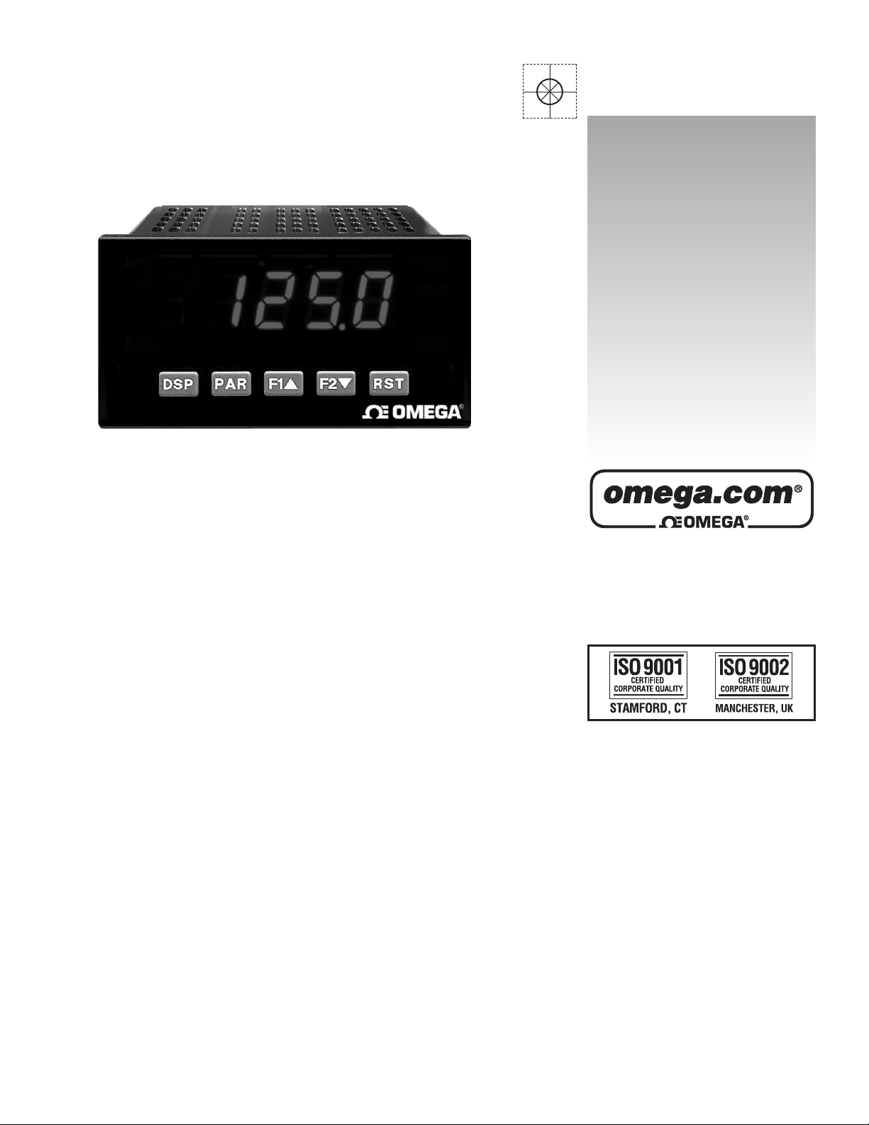
Digital PPanel MMeters
User’s Guide
LP0677X
Shop online at
omega.com
e-mail: [email protected]
For latest product manuals:
omegamanual.info
Page 2

OMEGAnet®Online Service
omega.com
Internet e-mail
Servicing North America:
U.S.A.: One Omega Drive, P.O. Box 4047
ISO 9001 Certified Stamford, CT 06907-0047
TEL: (203) 359-1660 FAX: (203) 359-7700
e-mail: [email protected]
Canada: 976 Bergar
Laval (Quebec) H7L 5A1, Canada
TEL: (514) 856-6928 FAX: (514) 856-6886
e-mail: [email protected]
For immediate technical or application assistance:
U.S.A. and Canada: Sales Service: 1-800-826-6342/1-800-TC-OMEGA
®
Customer Service: 1-800-622-2378/1-800-622-BEST
®
Engineering Service: 1-800-872-9436/1-800-USA-WHEN
®
Mexico: En Español: (001) 203-359-7803 e-mail: [email protected]
FAX: (001) 203-359-7807 [email protected]
Servicing Europe:
Czech Republic: Frystatska 184, 733 01 Karviná, Czech Republic
TEL: +420 (0)59 6311899 FAX: +420 (0)59 6311114
Toll Free: 0800-1-66342
e-mail: [email protected]
Germany/Austria: Daimlerstrasse 26, D-75392 Deckenpfronn, Germany
TEL: +49 (0)7056 9398-0 FAX: +49 (0)7056 9398-29
Toll Free in Germany: 0800 639 7678
e-mail: [email protected]
United Kingdom: One Omega Drive, River Bend Technology Centre
ISO 9002 Certified Northbank, Irlam, Manchester
M44 5BD United Kingdom
TEL: +44 (0)161 777 6611 FAX: +44 (0)161 777 6622
Toll Free in United Kingdom: 0800-488-488
e-mail: [email protected]
It is the policy of OMEGA Engineering, Inc. to comply with all worldwide safety and EMC/EMI
regulations that apply. OMEGA is constantly pursuing certification of its products to the European New
Approach Directives. OMEGA will add the CE mark to every appropriate device upon certification.
The information contained in this document is believed to be correct, but OMEGA accepts no liability for any
errors it contains, and reserves the right to alter specifications without notice.
WARNING : These products are not designed for use in, and should not be used for, human applications.
Page 3
3
z PROCESS, VOLTAGE, CURRENT, TEMPERATURE, AND STRAIN
GAGE INPUTS
z 5-DIGIT 0.56" RED SUNLIGHT READABLE DISPLAY
z VARIABLE INTENSITY DISPLAY
z 16 POINT SCALING FOR NON-LINEAR PROCESSES
z PROGRAMMABLE FUNCTION KEYS/USER INPUTS
z 9 DIGIT TOTALIZER (INTEGRATOR) WITH BATCHING
z OPTIONAL CUSTOM UNITS OVERLAY W/BACKLIGHT
z FOUR SETPOINT ALARM OUTPUTS (W/OPTION CARD)
z COMMUNICATION AND BUS CAPABILITIES (W/OPTION CARD)
z RETRANSMITTED ANALOG OUTPUT (W/OPTION CARD)
z PROGRAMMING SOFTWARE
z NEMA4X/IP65 SEALED FRONT BEZEL
GENERAL DESCRIPTION
The DP63x00 Panel Meters offer many features and performance capabilities
to suit a wide range of industrial applications. Available in five different models
to handle various analog inputs, including DC Voltage/Current, AC
Voltage/Current, Process, Temperature, and Strain Gage Inputs. Refer to pages
4 through 6 for the details on the specific models. The optional plug-in output
cards allow the opportunity to configure the meter for present applications,
while providing easy upgrades for future needs.
The meters employ a bright 0.56" LED display. The unit is available with a
red sunlight readable or a standard green LED. The intensity of display can be
adjusted from dark room applications up to sunlight readable, making it ideal
for viewing in bright light applications.
The meters provide a MAX and MIN reading memory with programmable
capture time. The capture time is used to prevent detection of false max or min
readings which may occur during start-up or unusual process events.
The signal totalizer (integrator) can be used to compute a time-input product.
This can be used to provide a readout of totalized flow, calculate service
intervals of motors or pumps, etc. The totalizer can also accumulate batch
weighing operations.
The meters have four setpoint outputs, implemented on Plug-in option cards.
The Plug-in cards provide dual FORM-C relays (5A), quad FORM-A (3A), or
either quad sinking or quad sourcing open collector logic outputs. The setpoint
alarms can be configured to suit a variety of control and alarm requirements.
RS232 and RS485 Communication and Modbus Capabilities are also
available as option cards. Readout values and setpoint alarm values can be
controlled through the bus. Additionally, the meters have a feature that allows a
remote computer to directly control the outputs of the meter. With an RS232 or
RS485 card installed, it is possible to configure the meter using a Windows
®
based program. The configuration data can be saved to a file for later recall.
A linear DC output signal is available as an optional Plug-in card. The card
provides either 20 mA or 10 Vsignals. The output can be scaled independent of
the input range and can track either the input, totalizer, max or min readings.
Once the meters have been initially configured, the parameter list may be
locked out from further modification in its entirety or only the setpoint values
can be made accessible.
The meters have been specifically designed for harsh industrial environments.
With NEMA 4X/IP65 sealed bezel and extensive testing of noise effects to CE
requirements, the meter provides a tough yet reliable application solution.
SAFETY SUMMARY
All safety related regulations, local codes and instructions that appear in this
literature or on equipment must be observed to ensure personal safety and to
prevent damage to either the instrument or equipment connected to it. If
equipment is used in a manner not specified by the manufacturer, the protection
provided by the equipment may be impaired.
Do not use this unit to directly command motors, valves, or other actuators
not equipped with safeguards. To do so can be potentially harmful to persons or
equipment in the event of a fault to the unit.
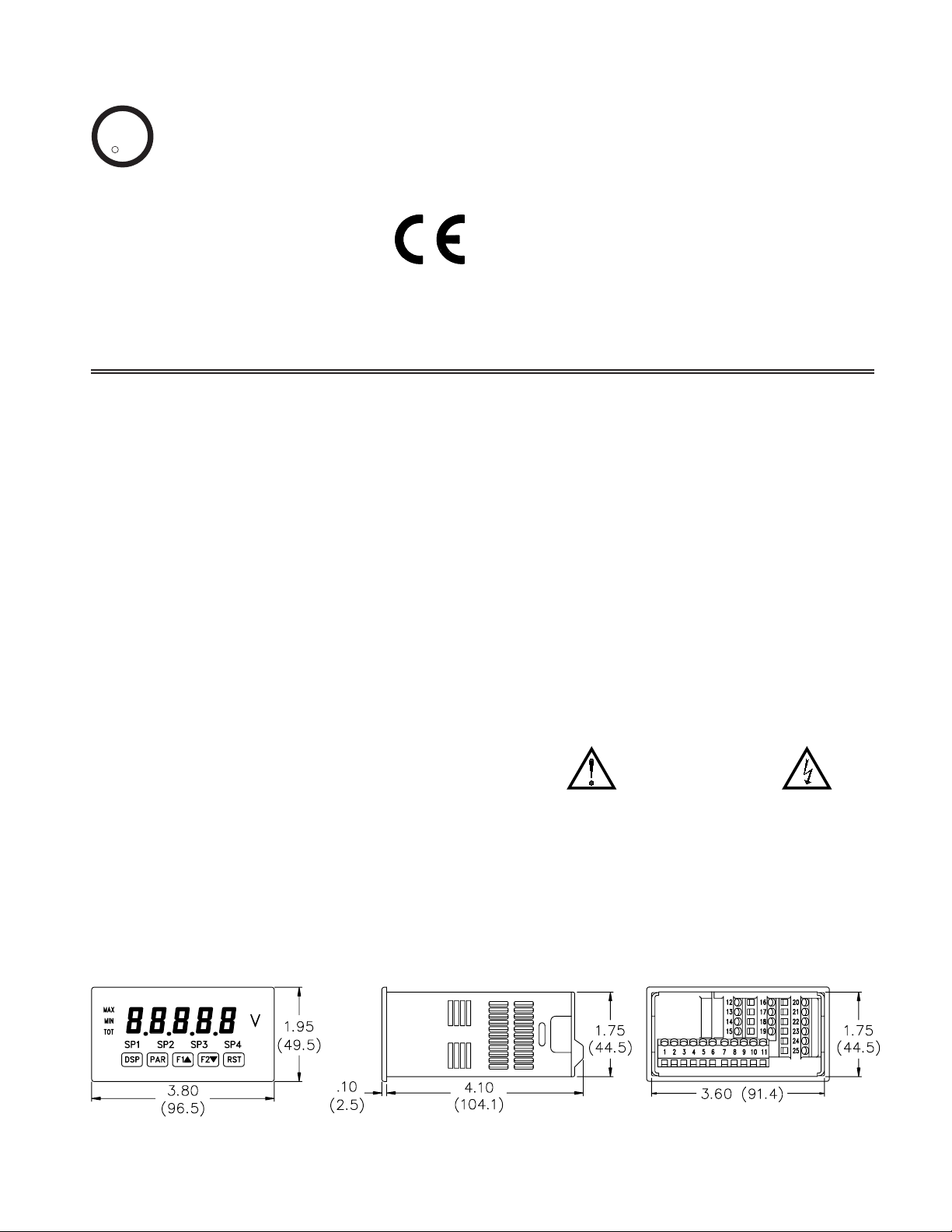
DIMENSIONS In inches (mm)
Note: Recommended minimum clearance (behind the panel) for mounting clip installation is
2.1" (53.4) H x 5.0" (127) W.
CAUTION: Risk of Danger
Read complete instructions prior to
installation and operation of the unit.
CAUTION: Risk of electric shock.
C
US LISTED
U
L
R
IND. CONT. EQ.
51EB
Page 4
4
GENERAL METER
SPECIFICATIONS
1. DISPLAY: 5 digit, 0.56" (14.2 mm) red sunlight readable or standard green
LEDs, (-19999 to 99999)
2. POWER:
AC Versions:
AC Power: 85 to 250 VAC, 50/60 Hz, 15 VA
Isolation: 2300 Vrms for 1 min. to all inputs and outputs.
DC Versions (Not available on DP63700):
DC Power: 11 to 36 VDC, 11 W
(derate operating temperature to 40° C if operating <15 VDC and three
plug-in option cards are installed)
AC Power: 24 VAC, ± 10%, 50/60 Hz, 15 VA
Isolation: 500 Vrms for 1 min. to all inputs and outputs (50 V working).
3. ANNUNCIATORS:
MAX - maximum readout selected
MIN - minimum readout selected
TOT - totalizer readout selected, flashes when total overflows
SP1 - setpoint alarm 1 is active
SP2 - setpoint alarm 2 is active
SP3 - setpoint alarm 3 is active
SP4 - setpoint alarm 4 is active
Units Label - optional units label backlight
4. KEYPAD: 3 programmable function keys, 5 keys total
5. A/D CONVERTER: 16 bit resolution
6. UPDATE RATES:
A/D conversion rate: 20 readings/sec.
Step response: 200 msec. max. to within 99% of final readout value
(digital filter and internal zero correction disabled)
700 msec. max. (digital filter disabled, internal zero correction enabled)
DP63700 Only: 1 sec max. to within 99% of final readout value (digital
filter disabled)
Display update rate: 1 to 20 updates/sec.
Setpoint output on/off delay time: 0 to 3275 sec.
Analog output update rate: 0 to 10 sec
Max./Min. capture delay time: 0 to 3275 sec.
7. DISPLAYMESSAGES:
“OLOL” - Appears when measurement exceeds + signal range.
“ULUL” - Appears when measurement exceeds - signal range
DP63500: “SHrt” - Appears when shorted sensor is detected. (RTD only)
DP63500: “OPEN” - Appears when open sensor is detected.
“. . . .” - Appears when display values exceed + display range.
“- . . .” - Appears when display values exceed - display range.
8. INPUT CAPABILITIES: See specific product specifications, pages 4-6
9. EXCITATION POWER: See specific product specifications, pages 4-6
10. LOW FREQUENCY NOISE REJECTION: (Does not apply to DP63700)
Normal Mode: > 60 dB @ 50 or 60 Hz ±1%, digital filter off
Common Mode: >100 dB, DC to 120 Hz
11. USER INPUTS: Three programmable user inputs
Max. Continuous Input: 30 VDC
Isolation To Sensor Input Common: Not isolated. (Not DP63700)
DP63700: Isolation To Sensor Input Common: 1400 Vrms for 1 min.
Working Voltage: 125 V
Response Time: 50 msec. max.
Logic State: Jumper selectable for sink/source logic
12. TOTALIZER:
Function:
Time Base: second, minute, hour, or day
Batch: Can accumulate (gate) input display from a user input
Time Accuracy: 0.01% typical
Decimal Point: 0 to 0.0000
Scale Factor: 0.001 to 65.000
Low Signal Cut-out: -19,999 to 99,999
Total: 9 digits, display alternates between high order and low order readouts
13. CUSTOM LINEARIZATION:
Data Point Pairs: Selectable from 2 to 16
Display Range: -19,999 to 99,999
Decimal Point: 0 to 0.0000
DP63500: Ice Point Compensation: user value (0.00 to 650.00 μV/°C)
14. MEMORY: Nonvolatile E
2
PROM retains all programmable parameters
and display values.
15. ENVIRONMENTALCONDITIONS:
Operating Temperature Range: 0 to 50°C (0 to 45°C with all three plug-in
cards installed)
Vibration According to IEC 68-2-6: 5 to 150 Hz, in X, Y, Z direction for 1.5
hours, 2g’s.
Shock According to IEC 68-2-27: Operational 25 g (10g relay), 11 msec in 3
directions.
Storage Temperature Range: -40 to 60°C
Operating and Storage Humidity: 0 to 85% max. RH non-condensing
Altitude: Up to 2000 meters
16. CERTIFICA TIONS AND COMPLIANCES:
SAFETY
UL Recognized Component, File #E313607, UL61010A-1, CSA C22.2
No. 1010-1
DP63500 Only: File # E123489, UL873, CSA C22.2 No. 24
Recognized to U.S. and Canadian requirements under the Component
Recognition Program of Underwriters Laboratories, Inc.
UL Listed, File # E313547, UL508, CSA C22.2 No. 14-M95
LISTED by Und. Lab. Inc. to U.S. and Canadian safety standards
Type 4X Enclosure rating (Face only), UL50
IEC 61010-1, EN 61010-1: Safety requirements for electrical
equipment for measurement, control, and laboratory use, Part I
IP65 Enclosure rating (Face only), IEC 529
IP20 Enclosure rating (Rear of unit), IEC 529
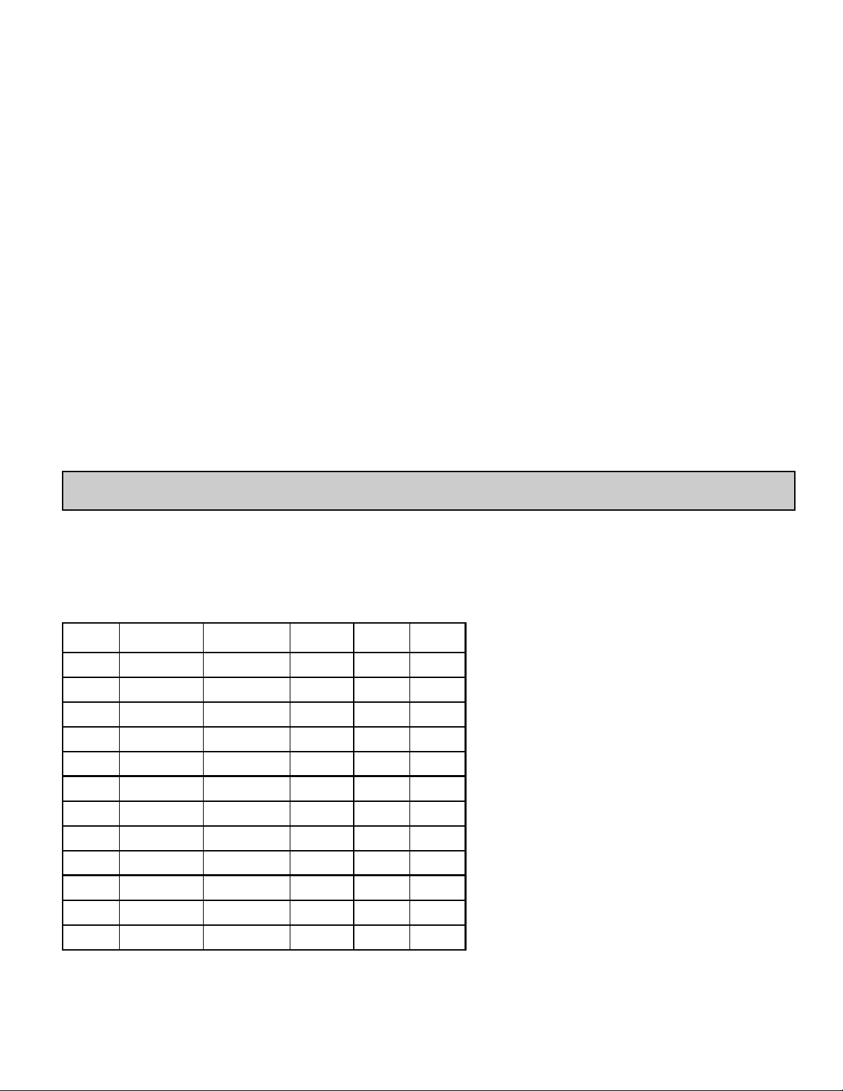
VIN> 3.6 VDC VIN< 0.9 VDC
Inactive
VIN< 0.9 VDC VIN> 3.6 VDC
Active
SINKING INPUTS
22 KΩΩpull-up to +5 V
SOURCING INPUTS
22 KΩΩpull-down
INPUT STATE
General Meter Specifications . . . . . . . . . . . . 4
Universal DC Input Panel Meter . . . . . . . . . . 5
Process Input Panel Meter . . . . . . . . . . . . . . 6
AC True RMS Voltage and Current Meter . . . 6
Strain Gage Input Panel Meter . . . . . . . . . . . 7
Thermocouple and RTD Input Meter . . . . . . 7
Optional Plug-In Cards . . . . . . . . . . . . . . . . . 8
Installing the Meter . . . . . . . . . . . . . . . . . . . . 9
Setting the Jumpers . . . . . . . . . . . . . . . . . . . 9
Wiring the Meter . . . . . . . . . . . . . . . . . . . . . 11
Reviewing the Front Buttons and Display . . 14
Programming the Meter . . . . . . . . . . . . . . . 15
Factory Service Operations . . . . . . . . . . . . 24
Parameter Value Chart . . . . . . . . . . . . . . . . 26
Programming Overview . . . . . . . . . . . . . . . 28
TABLE OF CONTENTS
Page 5
ELECTROMAGNETIC COMPATIBILITY
Notes:
1. Self-recoverable loss of performance during EMI disturbance at 10 V/m:
Measurement input and/or analog output signal may deviate during
EMI disturbance.
For operation without loss of performance:
Unit is mounted in a metal enclosure (Buckeye SM7013-0 or equivalent)
I/O and power cables are routed in metal conduit connected to earth
ground.
Refer to EMC Installation Guidelines section of the bulletin for additional
information.
17. CONNECTIONS: High compression cage-clamp terminal block
Wire Strip Length: 0.3" (7.5 mm)
Wire Gage: 30-14 AWG copper wire
Torque: 4.5 inch-lbs (0.51 N-m) max.
18. CONSTRUCTION: This unit is rated for NEMA 4X/IP65 outdoor use.
IP20 Touch safe. Installation Category II, Pollution Degree 2. One piece
bezel/case. Flame resistant. Synthetic rubber keypad. Panel gasket and
mounting clip included.
19. WEIGHT: 10.4 oz. (295 g)
5
Power mains class A
Enclosure class AEN 55011RF interference
Emissions to EN 50081-2
150 KHz - 80 MHz
Level 3; 10 V/rms EN 61000-4-6RF conducted interference
Level 3; 2 Kv power
Level 4; 2 Kv I/OEN 61000-4-4Fast transients (burst)
80 MHz - 1 GHz
Level 3; 10 V/m
1
EN 61000-4-3Electromagnetic RF fields
Level 3; 8 Kv air
Level 2; 4 Kv contactEN 61000-4-2Electrostatic discharge
200 Hz, 50% duty cycle
900 MHz ±5 MHz
Immunity to EN 50082-2
Level 3; 10 V/mENV 50204Simulation of cordless telephones
MODEL DP63600 - UNIVERSAL DC INPUT
* After 20 minute warm-up. Accuracy is specified in two ways:
Accuracy over an 18 to 28°C and 10 to 75% RH environment; and
accuracy over a 0 to 50°C and 0 to 85% RH (non-condensing
environment). Accuracy over the 0 to 50°C range includes the
temperature coefficient effect of the meter.
EXCITATION POWER:
Transmitter Power: 24 VDC, ±5%, regulated, 50 mAmax.
Reference Voltage: 2 VDC, ± 2%
Compliance: 1 kohm load min. (2 mA max.)
Temperature coefficient: 40 ppm/°C max.
Reference Current: 1.75 mADC, ± 2%
Compliance: 10 kohm load max.
Temperature coefficient: 40 ppm/°C max.
z FOUR VOLTAGE RANGES (300 VDC Max)
z FIVE CURRENT RANGES (2A DC Max)
z THREE RESISTANCE RANGES (10K Ohm Max)
z SELECTABLE 24 V, 2 V, 1.75 mAEXCITATION
DP63600 SPECIFICATIONS
INPUT RANGES:
INPUT
RANGE
ACCURACY*
(18 to 28°C)
ACCURACY*
(0 to 50°C)
IMPEDANCE/
COMPLIANCE
MAX
CONTINUOUS
OVERLOAD
RESOLUTION
±200 mVDC
0.03% of reading
+30 μV
0.12% of reading
+40 μV
1.066 Mohm 100 V
10 μV
±2 VDC
0.03% of reading
+0.3 mV
0.12% of reading
+0.4 mV
1.066 Mohm 300 V 0.1 mV
±20 VDC
0.03% of reading
+3 mV
0.12% of reading
+4 mV
1.066 Mohm 300 V 1 mV
±300 VDC
0.05% of reading
+30 mV
0.15% of reading
+40 mV
1.066 Mohm 300 V 10 mV
±200 μADC
0.03% of reading
+0.03 μA
0.12% of reading
+0.04μA
1.11 Kohm 15 mA 10 nA
±2 mADC
0.03% of reading
+0.3 μA
0.12% of reading
+0.4 μA
111 o hm 50 mA
0.1 μA
±20 mADC
0.03% of reading
+3μA
0.12% of reading
+4 μA
11.1 ohm 150 mA
1 μA
±200 mADC
0.05% of reading
+30 μA
0.15% of reading
+40 μA
1.1 ohm 500 mA
10 μA
±2 ADC
0.5% of reading
+0.3 mA
0.7% of reading
+0.4 mA
0.1 ohm 3 A 0.1 mA
100 ohm
0.05% of reading
+30 Mohm
0.2% of reading
+40 Mohm
0.175 V 30 V 0.01 ohm
1000 ohm
0.05% of reading
+0.3 ohm
0.2% of reading
+0.4 ohm
1.75 V 30 V 0.1 ohm
10 Kohm
0.05% of reading
+1 ohm
0.2% of reading
+1.5 ohm
17.5 V 30 V 1 ohm
Page 6
6
MODEL DP63700 - AC TRUE RMS VOLT AND
C
URRENT
z FOUR VOLTAGE RANGES (300 VAC Max)
z FIVE CURRENT RANGES (5 A Max)
z ACCEPTS AC OR DC COUPLED INPUTS
z THREE WAY ISOLATION: POWER, INPUT AND OUTPUTS
DP63700 SPECIFICATIONS
INPUT RANGES:
Isolation To Option Card Commons and User Input Commons: 125 Vrms
Isolation To AC Power Terminals: 250 Vrms
*Conditions for accuracy specification:
- 20 minutes warmup
- 18-28°C temperature range, 10-75% RH non-condensing
- 50 Hz - 400 Hz sine wave input
- 1% to 100% of range
- Add 0.1% reading + 20 counts error over 0-50°C range
- Add 0.2% reading + 10 counts error for crest factors up to 3, add 1% reading up to 5
- Add 0.5% reading + 10 counts of DC component
- Add 1% reading + 20 counts error over 20 Hz to 10 KHz range
** Non-repetitive surge rating: 15 Afor 5 seconds
*** Inputs are direct coupled to the input divider and shunts. Input signals with
high DC component levels may reduce the usable range.
MAX CREST FACTOR (Vp/VRMS): 5 @ Full Scale Input
INPUT COUPLING: AC or AC and DC
INPUT CAPACITANCE: 10 pF
COMMON MODE VOLTAGE: 125 VAC working
COMMON MODE REJECTION: (DC to 60 Hz) 100 dB
INPUT
RANGE
ACCURACY*
MAX DC
BLOCKING
IMPEDANCE
(60 Hz)
MAX
CONTINUOUS
OVERLOAD
RESOLUTION
2 mA
0.1% of reading
+2 μA
±50 mA
111 ohm 50 mA
0.1 μA
20 mA
0.1% of reading
+20 μA
±150 mA
11.1 ohm 150 mA
1 μA
200 mA
0.1% of reading
+0.2 mA
±500 mA
1.1 ohm 500 mA
10 μA
5 A
0.5% of reading
+5 mA
±7 A***
0.02 ohm 7 A** 1 mA
200 mV
0.1% of reading
+0.4 mV
±10 V
686 Kohm 30 V 0.01 mV
2 V
0.1% of reading
+2 mV
±50 V
686 Kohm 30 V 0.1 mV
20 V
0.1% of reading
+20 mV
±300 V
686 Kohm 300 V 1 mV
300 V
0.2% of reading
+0.3 V
±300 V***
686 Kohm 300 V 0.1 V
200 μA
0.1% of reading
+0.4 μA
±15 mA
1.11 Kohm 15 mA
0.01 μA
MODEL DP63800 - PROCESS INPUT
z DUAL RANGE INPUT (20 mA or 10 VDC)
z 24 VDC TRANSMITTER POWER
DP63800 SPECIFICATIONS
SENSOR INPUTS:
* After 20 minute warm-up. Accuracy is specified in two ways: Accuracy over an 18
to 28°C and 10 to 75% RH environment; and accuracy over a 0 to 50°C and 0 to
85%RH (non-condensing environment). Accuracy over the 0 to 50°C range
includes the temperature coefficient effect of the meter.
EXCITATION POWER:
Transmitter Power: 24 VDC, ±5%, regulated, 50 mAmax.
INPUT
(RANGE)
ACCURACY*
(18 to 28°C)
ACCURACY*
(0 to 50°C)
IMPEDANCE/
COMPLIANCE
MAX
CONTINUOUS
OVERLOAD
DISPLAY
RESOLUTION
20 mA
(-2 to 26 mA)
0.03% of
reading +2 μA
0.12% of
reading +3 μA
20 ohm 150 mA
1 μA
10 VDC
(-1 to 13 VDC)
0.03% of
reading +2 mV
0.12% of
reading +3 mV
500 Kohm 300 V 1 mV
Page 7
7
MODEL DP63900 - STRAIN GAGE INPUT
z LOAD CELL, PRESSURE AND TORQUE BRIDGE INPUTS
z DUAL RANGE INPUT: ±24 mV OR ±240 mV
z SELECTABLE 5 VDC OR 10 VDC BRIDGE EXCITATION
z PROGRAMMABLE AUTO-ZERO TRACKING
DP63900 SPECIFICATIONS
SENSOR INPUTS:
CONNECTION TYPE: 4-wire bridge (differential)
2-wire (single-ended)
COMMON MODE RANGE (w.r.t. input common): 0 to +5 VDC
Rejection: 80 dB (DC to 120 Hz)
BRIDGE EXCITATION :
Jumper Selectable: 5 VDC @ 65 mA max., ±2%
10 VDC @ 125 mA max., ±2%
Temperature coefficient (ratio metric): 20 ppm/°C max.
INPUT RANGE
ACCURACY*
(18 to 28°C)
ACCURACY*
(0 to 50°C)
IMPEDANCE
MAX
CONTINUOUS
OVERLOAD
RESOLUTION
±24 mVDC
0.02% of
reading +3 μV
0.07% of
reading +4 μV
100 Mohm 30 V
1 μV
±240 mVDC
0.02% of
reading +30 μV
0.07% of
reading +40 μV
100 Mohm 30 V
10 μV
* After 20 minute warm-up. Accuracy is specified in two ways: Accuracy over an 18
to 28°C and 10 to 75% RH environment; and accuracy over a 0 to 50°C and 0 to
85% RH (non-condensing environment). Accuracy over the 0 to 50°C range
includes the temperature coefficient effect of the meter.
MODEL DP63500 - THERMOCOUPLE AND RTD INPUT
z THERMOCOUPLE AND RTD INPUTS
z CONFORMS TO ITS-90 STANDARDS
z CUSTOM SCALING FOR NON-STANDARD PROBES
z TIME-TEMPERATURE INTEGRATOR
DP63500 SPECIFICATIONS
READOUT:
Resolution: Variable: 0.1, 0.2, 0.5, or 1, 2, or 5 degrees
Scale: F or C
Offset Range: -19,999 to 99,999 display units
THERMOCOUPLE INPUTS:
Input Impedance: 20 MΩ
Lead Resistance Effect: 0.03μV/ohm
Max. Continuous Overvoltage: 30 V
RTD INPUTS:
Type: 3 or 4 wire, 2 wire can be compensated for lead wire resistance
Excitation current: 100 ohm range: 165 μA
10 ohm range: 2.6 mA
Lead resistance: 100 ohm range: 10 ohm/lead max.
10 ohm range: 3 ohms/lead max.
Max. continuous overload: 30 V
CUSTOM RANGE: Up to 16 data point pairs
Input range: -10 to 65 mV
0 to 400 ohms, high range
0 to 25 ohms, low range
Display range: -19999 to 99999
STANDARD
***
ACCURACY*
(0 to 50°C)
ACCURACY*
(18 to 28°C)
RANGE
no official
standard
0.9°C0.4°C-100 to 260°C
10 ohm Copper
alpha = .00427
INPUT TYPE
no official
standard
0.5°C0.2°C-80 to 260°C
120 ohm Nickel
alpha = .00672
no official
standard
1.6°C0.4°C-200 to 850°C
100 ohm Pt
alpha = .003919
IEC 7511.6°C0.4°C-200 to 850°C
100 ohm Pt
alpha = .00385
0.20% of reading
+ 0.007 Ω
0.04% of reading
+ 0.005 Ω
0 to 25 Ω
(1 MΩ res.)
Custom
10 ohm range
0.12% of reading
+ 0.05 Ω
0.02% of reading
+ 0.04 Ω
0 to 400 Ω
(10 MΩ res.)
Custom
100 ohm range
ACCURACY*
(0 to 50°°C)
0.12% of reading
+ 5μV
0.02% of reading
+ 4μV
-10 to 65mV
(1 μV res.)
Custom
mV range
ACCURACY*
(18 to 28°°C)
RANGEINPUT TYPE
WIRE COLOR
INPUT
TYPE
RANGE
ACCURACY*
(0 to 50°C)
STANDARD
ANSI BS 1843
T
-200 to 400°C
-270 to -200°C
1.2°C
**
2.1°C
ITS-90
(+) blue
(-) red
(+) white
(-) blue
E
-200 to 871°C
-270 to -200°C
1.0°C
**
2.4°C
ITS-90
(+) purple
(-) red
(+) brown
(-) blue
J -200 to 760°C 1.1°C 2.3°C ITS-90
(+) white
(-) red
(+) yellow
(-) blue
K
-200 to 1372°C
-270 to -200°C
1.3°C
**
3.4°C
ITS-90
(+) yellow
(-) red
(+) brown
(-) blue
R -50 to 1768°C 1.9°C 4.0°C ITS-90
no
standard
(+) white
(-) blue
S -50 to 1768°C 1.9°C 4.0°C ITS-90
no
standard
(+) white
(-) blue
B
100 to 300°C
300 to 1820°C
3.9°C
2.8°C
5.7°C
4.4°C
ITS-90
no
standardnostandard
N
1.3°C
**
3.1°C
ITS-90
(+) orange
(-) red
(+) orange
(-) blue
C
(W5/W26)
0 to 2315°C 1.9°C 6.1°C
ASTM
E988-90***nostandardnostandard
*After 20 min. warm-up. Accuracy is specified in two ways: Accuracy over an 18
to 28°C and 15 to 75% RH environment; and Accuracy over a 0 to 50°C and 0 to
85% RH (non condensing) environment. Accuracy specified over the 0 to 50°C
operating range includes meter tempco and ice point tracking effects. The
specification includes the A/D conversion errors, linearization conformity, and
thermocouple ice point compensation. Total system accuracy is the sum of meter
and probe errors. Accuracy may be improved by field calibrating the meter readout
at the temperature of interest.
** The accuracy over the interval -270 to -200°C is a function of temperature,
ranging from 1°C at -200°C and degrading to 7°C at -270°C. Accuracy may be
improved by field calibrating the meter readout at the temperature of interest.
*** These curves have been corrected to ITS-90.
ACCURACY*
(18 to 28°C)
-200 to 1300°C
-270 to -200°C
Page 8
8
WARNING: Disconnect all power to the unit before
installing Plug-in cards.
Adding Option Cards
The DP63x00 and LDP63x00 series meters can be fitted with up to three
optional plug-in cards. The details for each plug-in card can be reviewed in the
specification section below. Only one card from each function type can be
installed at one time. The function types include Setpoint Alarms (LDP6-CDS),
Communications (LDP6-CDC), and Analog Output (LDP6-CDL). The plug-in
cards can be installed initially or at a later date.
DP63700 Isolation Specifications For All Option Cards
Isolation To Sensor Commons: 1400 Vrms for 1 min.
Working Voltage: 125 V
Isolation to User Input Commons: 500 Vrms for 1 min.
Working Voltage 50 V
COMMUNICATION CARDS (LDP6-CDC)
A variety of communication protocols are available for the DP63x00 and
LDP63x00 series. Only one of these cards can be installed at a time. When
programming the unit via RLCPro, a Windows
®
based program, the RS232 or
RS485 Cards must be used.
SERIAL COMMUNICATIONS CARD
Type: RS485 or RS232
Isolation To Sensor & User Input Commons: 500 Vrms for 1 min.
Working Voltage: 50 V. Not Isolated from all other commons.
Data: 7/8 bits
Baud: 300 to 19,200
Parity: no, odd or even
Bus Address: Selectable 0 to 99, Max. 32 meters per line (RS485)
Transmit Delay: Selectable for 2 to 50 msec or 50 to 100 msec (RS485)
MODBUS CARD
Type: RS485; RTU and ASCII MODBUS modes
Isolation To Sensor & User Input Commons: 500 Vrms for 1 minute.
Working Voltage: 50 V. Not isolated from all other commons.
Baud Rates: 300 to 38400.
Data: 7/8 bits
Parity: No, Odd, or Even
Addresses: 1 to 247.
Transmit Delay: Programmable; See Transmit Delay explanation.
LINEAR DC OUTPUT (LDP6-CDL)
Either a 0(4)-20 mA or 0-10 V retransmitted linear DC output is available
from the analog output plug-in card. The programmable output low and high
scaling can be based on various display values. Reverse slope output is possible
by reversing the scaling point positions.
LDP6-CDL10 - Retransmitted Analog Output Card
ANALOG OUTPUT CARD
Types: 0 to 20 mA, 4 to 20 mAor 0 to 10 VDC
Isolation To Sensor & User Input Commons: 500 Vrms for 1 min.
Working Voltage: 50 V. Not Isolated from all other commons.
Accuracy: 0.17% of FS (18 to 28°C); 0.4% of FS (0 to 50°C)
Resolution: 1/3500
Compliance: 10 VDC: 10 KΩ load min., 20 mA: 500 Ω load max.
Update time: 200 msec. max. to within 99% of final output value (digital
filter and internal zero correction disabled)
700 msec. max. (digital filter disabled, internal zero correction enabled)
SETPOINT CARDS (LDP6-CDS)
The DP63x00 and LDP63x00 series has 4 available setpoint alarm output
plug-in cards. Only one of these cards can be installed at a time. (Logic state of
the outputs can be reversed in the programming.) These plug-in cards include:
LDP6-CDS10 - Dual Relay, FORM-C, Normally open & closed
LDP6-CDS20 - Quad Relay, FORM-A, Normally open only
LDP6-CDS30 - Isolated quad sinking NPN open collector
LDP6-CDS40 - Isolated quad sourcing PNP open collector
DUAL RELAY CARD
Type: Two FORM-C relays
Isolation To Sensor & User Input Commons: 2000 Vrms for 1 min.
Working Voltage: 240 Vrms
Contact Rating:
One Relay Energized: 5 amps @ 120/240 VAC or 28 VDC (resistive load),
1/8 HP @120 VAC, inductive load
Total current with both relays energized not to exceed 5 amps
Life Expectancy: 100 K cycles min. at full load rating. External RC snubber
extends relay life for operation with inductive loads
QUAD RELAY CARD
Type: Four FORM-Arelays
Isolation To Sensor & User Input Commons: 2300 Vrms for 1 min.
Working Voltage: 250 Vrms
Contact Rating:
One Relay Energized: 3 amps @ 240 VAC or 30 VDC (resistive load), 1/10
HP @120 VAC, inductive load
Total current with all four relays energized not to exceed 4 amps
Life Expectancy: 100K cycles min. at full load rating. External RC snubber
extends relay life for operation with inductive loads
QUAD SINKING OPEN COLLECTOR CARD
Type: Four isolated sinking NPN transistors.
Isolation To Sensor & User Input Commons: 500 Vrms for 1 min.
Working Voltage: 50 V. Not Isolated from all other commons.
Rating: 100 mA max @ V
SAT
= 0.7 V max. V
MAX
= 30 V
QUAD SOURCING OPEN COLLECTOR CARD
Type: Four isolated sourcing PNPtransistors.
Isolation To Sensor & User Input Commons: 500 Vrms for 1 min.
Working Voltage: 50 V. Not Isolated from all other commons.
Rating: Internal supply: 24 VDC ± 10% , 30 mA max. total
External supply: 30 VDC max., 100 mA max. each output
ALL FOUR SETPOINT CARDS
Response Time: 200 msec. max. to within 99% of final readout value (digital
filter and internal zero correction disabled)
700 msec. max. (digital filter disabled, internal zero correction enabled)
OPTIONAL P
LUG-IN OUTPUT
CARDS
LDP6-CDC20 - RS232 Serial
LDP6-CDC40 - ModbusLDP6-CDC10 - RS485 Serial
ACCESSORIES
UNITS LABEL KIT - Not required for DP63500
Each meter has a units indicator with backlighting that can be customized
using the Units Label Kit. The backlight is controlled in the programming.
Each DP63500 meter is shipped with °F and °C overlay labels which can be
installed into the meter’s bezel display assembly.
PROGRAMMING SOFTWARE
DP6-SOFT is a Windows®based program that allows configuration of the
DP63x00 meters from a PC. The software offers standard drop-down menu
commands, that make it easy to program the meter. The DP63x00 program can
then be saved in a PC file for future use. A serial plug-in card is required to
program the meter using the software.
Page 9
9
Installation
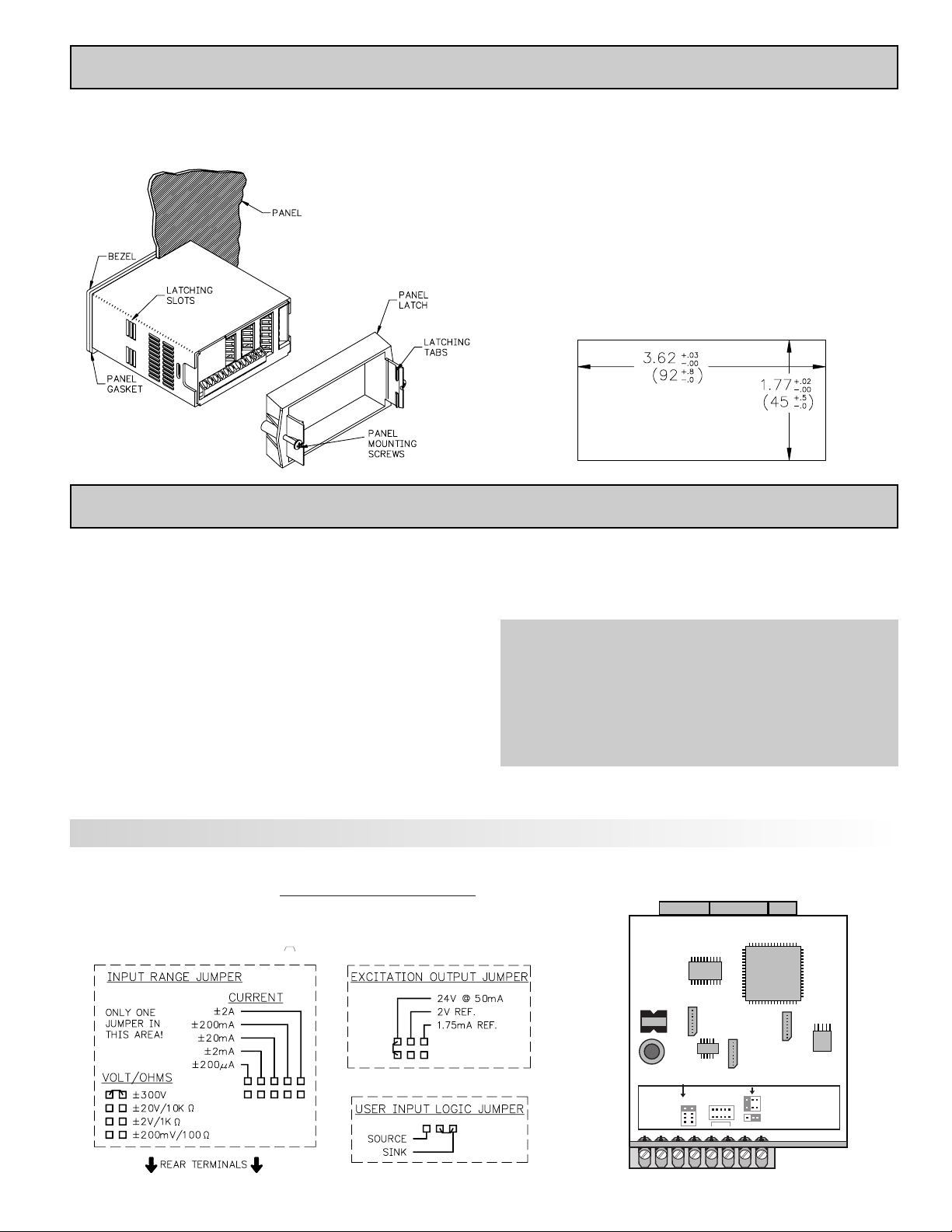
The DP63x00meets NEMA 4X/IP65 requirements when properly installed.
The unit is intended to be mounted into an enclosed panel. Prepare the panel
cutout to the dimensions shown. Remove the panel latch from the unit. Slide
the panel gasket over the rear of the unit
to the back of the bezel. The unit
should be installed fully
assembled. Insert the unit into
the panel cutout.
While holding the unit in place, push the panel latch over the rear of the unit
so that the tabs of the panel latch engage in the slots on the case. The panel
latch should be engaged in the farthest forward slot possible. To achieve a
proper seal, tighten the latch screws evenly until the unit is snug in the panel
(Torque to approximately 7 in-lbs [79N-cm]). Do not over-tighten the screws.
Installation Environment
The unit should be installed in a location that does not exceed the maximum
operating temperature and provides good air circulation. Placing the unit near
devices that generate excessive heat should be avoided.
The bezel should be cleaned only with a soft cloth and neutral soap product.
Do NOT use solvents. Continuous exposure to direct sunlight may accelerate
the aging process of the bezel.
Do not use tools of any kind (screwdrivers, pens, pencils, etc.) to operate the
keypad of the unit.
PANEL CUT-OUT
1.0 INSTALLING THE METER
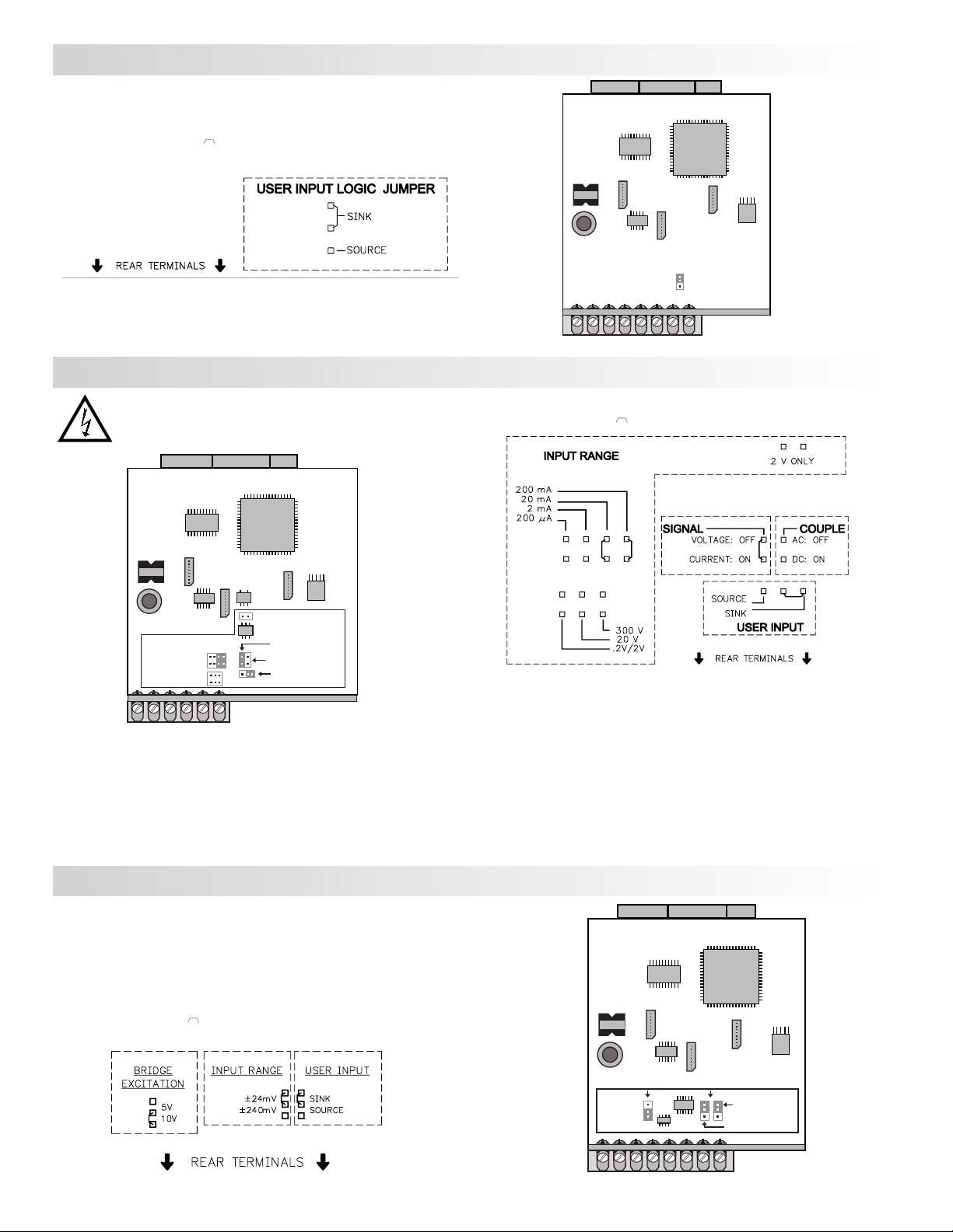
2.0 SETTING THE JUMPERS
The meter can have up to four jumpers that must be checked and / or changed
prior to applying power. The following Jumper Selection Figures show an
enlargement of the jumper area.
To access the jumpers, remove the meter base from the case by firmly
squeezing and pulling back on the side rear finger tabs. This should lower the
latch below the case slot (which is located just in front of the finger tabs). It is
recommended to release the latch on one side, then start the other side latch.
Input Range Jumper
This jumper is used to select the proper input range. The input range selected
in programming must match the jumper setting. Select a range that is high enough
to accommodate the maximum input to avoid overloads. The selection is different
for each meter. See the Jumper Selection Figure for appropriate meter.
Excitation Output Jumper
If your meter has excitation, this jumper is used to select the excitation range
for the application. If excitation is not being used, it is not necessary to check or
move this jumper.
User Input Logic Jumper
This jumper selects the logic state of all the user inputs. If the user inputs are
not used, it is not necessary to check or move this jumper.
DP63700:
Signal Jumper
This jumper is used to select the signal type. For current signals, the jumper
is installed. For voltage signals, remove the jumper from the board. (For 2 V
inputs, this removed jumper can be used in the “2 V only” location.)
Couple Jumper
This jumper is used for AC / DC couple. If AC couple, then the jumper is
removed from the board. If DC couple is used, then the jumper is installed.
DP63600 Jumper Selection
Main
Circuit
Board
JUMPER
LOCATION
JUMPER
LOCATION
CURRENT
EXCITATION
USER INPUT
VOLT/
OHM
JUMPER SELECTIONS
The indicates factory setting.
Input Range Jumper
One jumper is used for voltage/ohms or current input ranges. Select the proper input range high
enough to avoid input signal overload. Only one jumper is allowed in this area
. Do not have a jumper
in both the voltage and current ranges at the same time. Avoid placing the jumper across two ranges.
Page 10
10
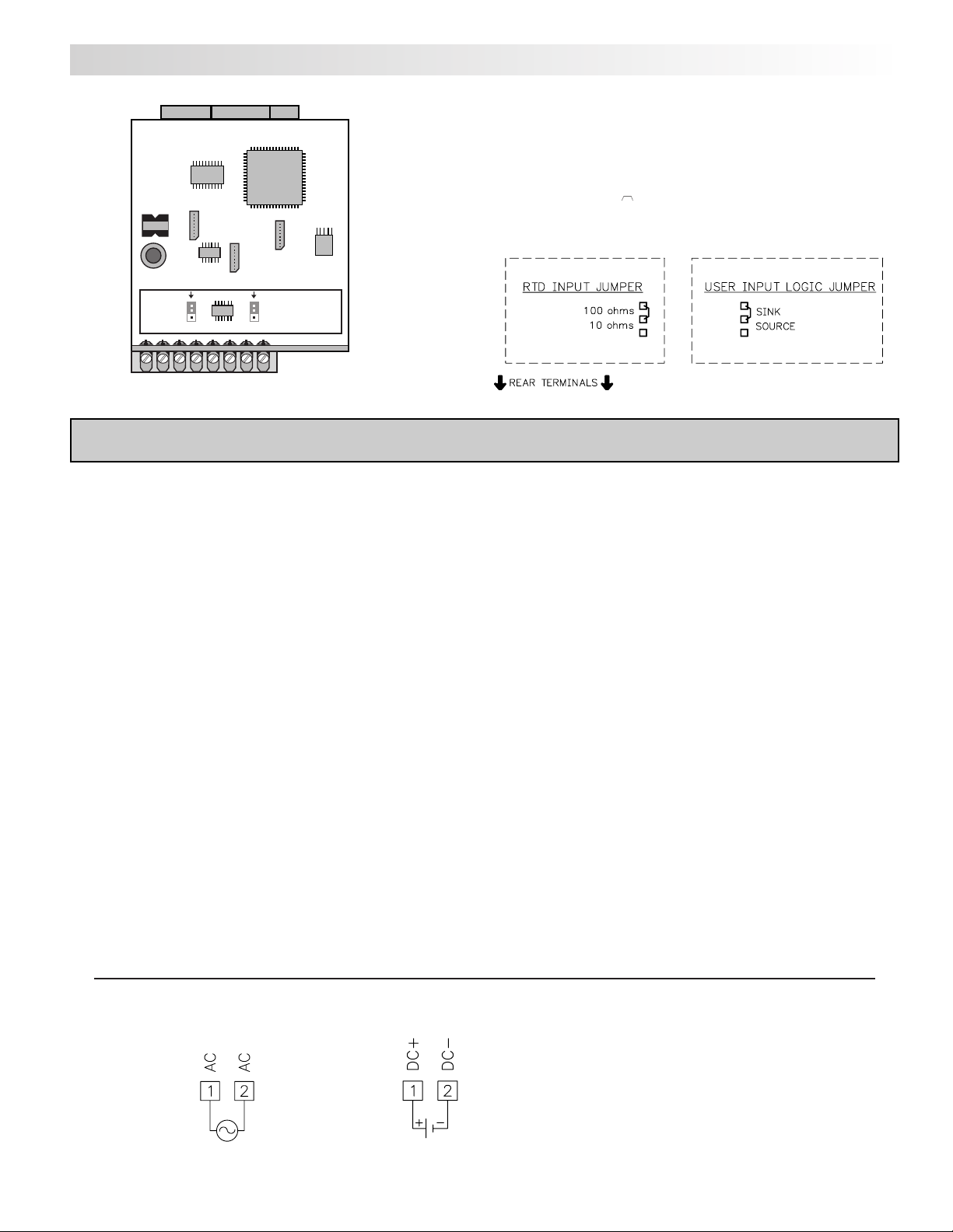
DP63800 Jumper Selection
DP63900 Jumper Selection
JUMPER SELECTIONS
The indicates factory setting.
Main
Circuit
Board
USER INPUT
JUMPER
LOCATION
Main
Circuit
Board
JUMPER
LOCATION
JUMPER
LOCATION
USER INPUT
INPUT RANGE
BRIDGE
JUMPER SELECTIONS
The indicates factory setting.
Bridge Excitation
One jumper is used to select bridge excitation to allow use of the higher sensitivity 24 mV input
range. Use the 5 V excitation with high output (3 mV/V) bridges. The 5 V excitation also reduces
bridge power compared to 10 V excitation.
A maximum of four 350 ohm load cells can be driven by the internal bridge excitation voltage.
DP63700 Jumper Selection
JUMPER SELECTIONS
The indicates factory setting.
Signal Jumper
One jumper is used for the input signal type. For current signals, the jumper
is installed. For voltage signals, remove the jumper from the board. (For 2 V
inputs, this removed jumper can be used in the “2 V only” location.)
Couple Jumper
One jumper is used for AC / DC couple. If AC couple is used, then the jumper
is removed from the board. If DC couple is used, then the jumper is installed.
Input Range Jumper
For most inputs, one jumper is used to select the input range. However, for
the following ranges, set the jumpers as stated:
5 A: Remove all jumpers from the input range.
2 V: Install one jumper in “.2/2V” position and one jumper in “2 V only”.
All Other Ranges: One jumper in the selected range only.
Do not have a jumper in both the voltage and current ranges at the same time.
Avoid placing a jumper across two ranges.
CAUTION: To maintain the electrical safety of the meter, remove
unneeded jumpers completely from the meter. Do not move the
jumpers to positions other than those specified.
Main
Circuit
Board
Jumper
Locations
CURR/VOLT
SIGNAL
2 V ONLY
USER INPUT
AC/DC COUPLE
VOLTAGE
CURRENT
RANGES
Page 11
11
WIRING OVERVIEW
Electrical connections are made via screw-clamp terminals located on the
back of the meter. All conductors should conform to the meter ’s voltage and
current ratings. All cabling should conform to appropriate standards of good
installation, local codes and regulations. It is recommended that power supplied
to the meter (DC or AC) be protected by a fuse or circuit breaker.
When wiring the meter, compare the numbers embossed on the back of the
meter case against those shown in wiring drawings for proper wire position.
Strip the wire, leaving approximately 0.3" (7.5 mm) bare lead exposed (stranded
wires should be tinned with solder). Insert the lead under the correct screwclamp terminal and tighten until the wire is secure. (Pull wire to verify
tightness.) Each terminal can accept up to one #14 AWG (2.55 mm) wire, two
#18 AWG (1.02 mm), or four #20 AWG (0.61 mm).
EMC INSTALLATION GUIDELINES
Although this meter is designed with a high degree of immunity to ElectroMagnetic Interference (EMI), proper installation and wiring methods must be
followed to ensure compatibility in each application. The type of the electrical
noise, its source or the method of coupling into the unit may be different for
various installations.Listed below are some EMC guidelines for successful
installation in an industrial environment.
1. The meter should be mounted in a metal enclosure, which is properly
connected to protective earth.
2. With use of the lower input ranges or signal sources with high source
impedance, the use of shielded cable may be necessary. This helps to guard
against stray AC pick-up. Attach the shield to the input common of the meter.
Line voltage monitoring and 5A CT applications do not usually require
shielding.
3. To minimize potential noise problems, power the meter from the same power
branch, or at least the same phase voltage as that of the signal source.
4. Never run Signal or Control cables in the same conduit or raceway with AC
power lines, conductors feeding motors, solenoids, SCR controls, and
heaters, etc. The cables should be run in metal conduit that is properly
grounded. This is especially useful in applications where cable runs are long
and portable two-way radios are used in close proximity or if the installation
is near a commercial radio transmitter.
5. Signal or Control cables within an enclosure should be routed as far away as
possible from contactors, control relays, transformers, and other noisy
components.
6. In extremely high EMI environments, the use of external EMI suppression
devices, such as ferrite suppression cores, is effective. Install them on Signal
and Control cables as close to the unit as possible. Loop the cable through the
core several times or use multiple cores on each cable for additional
protection. Install line filters on the power input cable to the unit to suppress
power line interference. Install them near the power entry point of the
enclosure. The following EMI suppression devices (or equivalent) are
recommended:
Ferrite Suppression Cores for signal and control cables:
Fair-Rite # 0443167251
TDK # ZCAT3035-1330A
Steward #28B2029-0A0
Line Filters for input power cables:
Schaffner # FN610-1/07
Schaffner # FN670-1.8/07
Corcom #1VR3
Note: Reference manufacturer’s instructions when installing a line filter.
7. Long cable runs are more susceptible to EMI pickup than short cable runs.
Therefore, keep cable runs as short as possible.
8. Switching of inductive loads produces high EMI. Use of snubbers across
inductive loads suppresses EMI.
3.0 WIRING THE METER
3.1 POWER WIRING
AC Power
Terminal 1: VAC
Terminal 2: VAC
DC Power
Terminal 1: +VDC
Terminal 2: -VDC
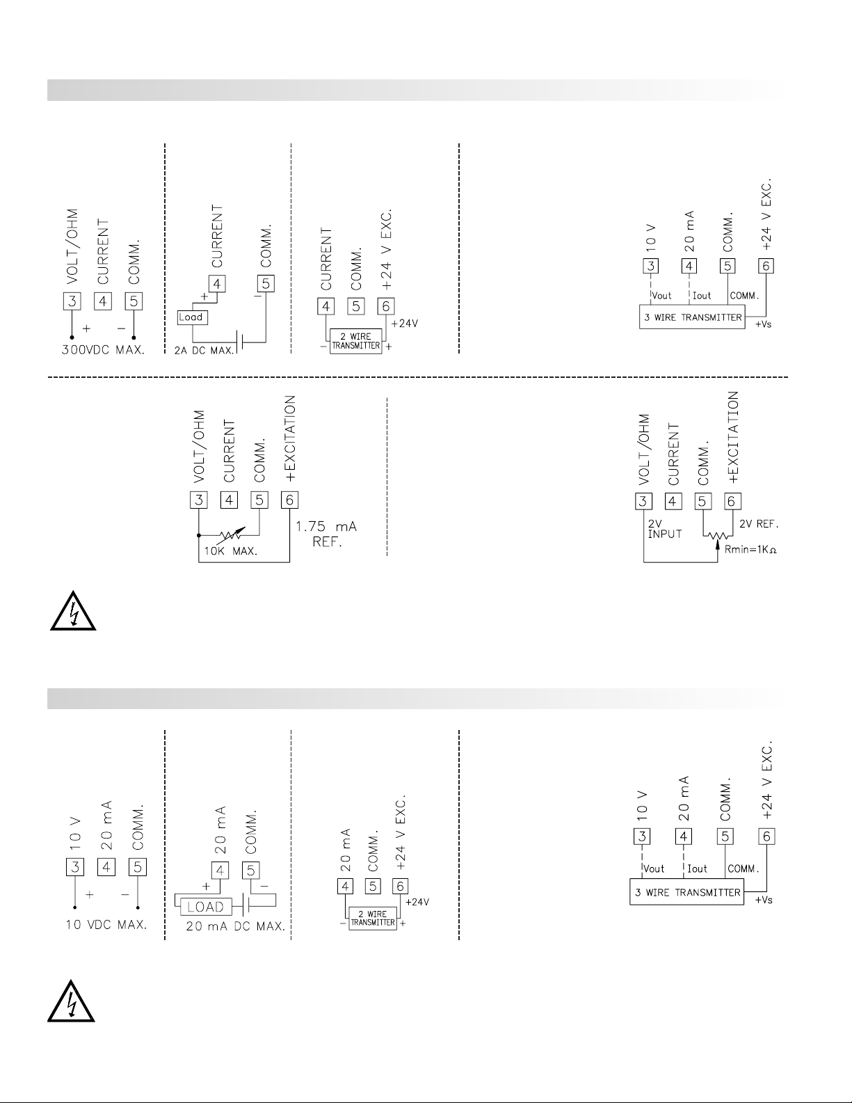
DP63500 Jumper Selection
Main
Circuit
Board
JUMPER
LOCATION
JUMPER
LOCATION
USER INPUT
RTD
INPUT
JUMPER SELECTIONS
The indicates factory setting.
RTD Input Jumper
One jumper is used for RTD input ranges. Select the proper range to match
the RTD probe being used. It is not necessary to remove this jumper when
not using RTD probes.
Page 12
12
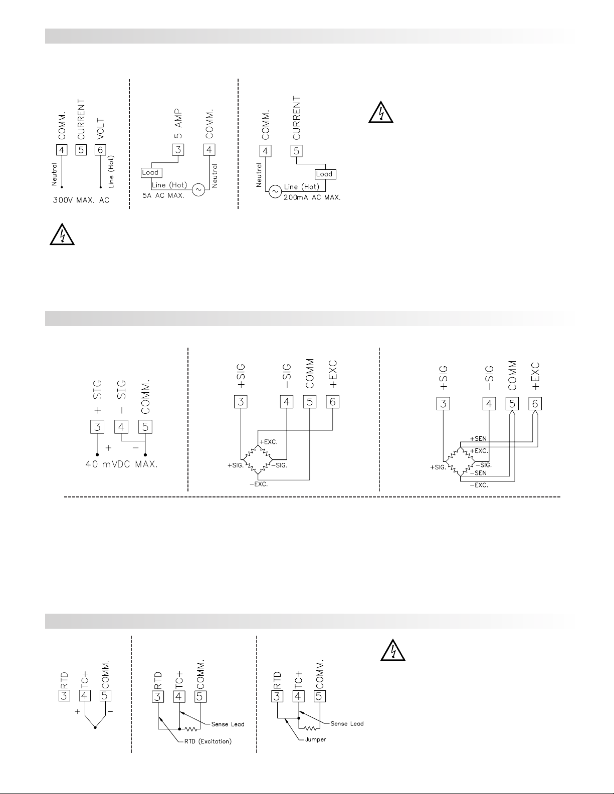
Current Signal
(self powered)
Terminal 4: +ADC
Terminal 5: -ADC
Voltage Signal
(self powered)
Terminal 3: +VDC
Terminal 5: -VDC
Current Signal (2 wire
requiring excitation)
Terminal 4: -ADC
Terminal 6: +ADC
Excitation Jumper: 24 V
Before connecting signal wires, the Input Range Jumper and Excitation Jumper should be verified for proper position.
3.2 INPUT SIGNAL WIRING
Current Signal (3 wire
requiring excitation)
Terminal 4: +ADC (signal)
Terminal 5: -ADC (common)
Terminal 6: +Volt supply
Excitation Jumper: 24 V
Voltage Signal (3 wire
requiring excitation)
Terminal 3: +VDC (signal)
Terminal 5: -VDC (common)
Terminal 6: +Volt supply
Excitation Jumper: 24 V
Resistance Signal
(3 wire requiring
excitation)
Terminal 3: Resistance
Terminal 5: Resistance
Terminal 6: Jumper to
terminal 3
Excitation Jumper:
1.75 mA REF.
Potentiometer Signal
(3 wire requiring excitation)
Terminal 3: Wiper
Terminal 5: Low end of pot.
Terminal 6: High end of pot.
Excitation Jumper: 2 V REF.
Input Range Jumper: 2 Volt
Module 1 Input Range: 2 Volt
Note: The Apply signal scaling style
should be used because the signal will
be in volts.
Current Signal
(self powered)
Terminal 4: +ADC
Terminal 5: -ADC
Voltage Signal
(self powered)
Terminal 3: +VDC
Terminal 5: -VDC
Current Signal (2 wire
requiring excitation)
Terminal 4: -ADC
Terminal 6: +ADC
DP63800 INPUT SIGNAL WIRING
DP63600 INPUT SIGNAL WIRING
Current Signal (3 wire
requiring excitation)
Terminal 4: +ADC (signal)
Terminal 5: -ADC (common)
Terminal 6: +Volt supply
Voltage Signal (3 wire
requiring excitation)
Terminal 3: +VDC (signal)
Terminal 5: -VDC (common)
Terminal 6: +Volt supply
CAUTION: Sensor input common is NOT isolated from user input common. In order to preserve the safety of the meter application, the sensor input
common must be suitably isolated from hazardous live earth referenced voltages; or input common must be at protective earth ground potential. If not,
hazardous live voltage may be present at the User Inputs and User Input Common terminals. Appropriate considerations must then be given to the
potential of the user input common with respect to earth common; and the common of the isolated plug-in cards with respect to input common.
CAUTION: Sensor input common is NOT isolated from user input common. In order to preserve the safety of the meter application, the sensor input
common must be suitably isolated from hazardous live earth referenced voltages; or input common must be at protective earth ground potential. If not,
hazardous live voltage may be present at the User Inputs and User Input Common terminals. Appropriate considerations must then be given to the
potential of the user input common with respect to earth common; and the common of the isolated plug-in cards with respect to input common.
Page 13
13
4-Wire Bridge Input
2-Wire Single
Ended Input
6-Wire Bridge Input
DEADLOAD COMPENSATION
In some cases, the combined deadload and liveload output may exceed the
range of the 24 mV input. To use this range, the output of the bridge can be offset
a small amount by applying a fixed resistor across one arm of the bridge. This
shifts the electrical output of the bridge downward to within the operating range
of the meter. A 100 K ohm fixed resistor shifts the bridge output approximately
-10 mV (350 ohm bridge, 10 V excitation).
Connect the resistor between +SIG and -SIG. Use a metal film resistor with a
low temperature coefficient of resistance.
BRIDGE COMPLETION RESISTORS
For single strain gage applications, bridge completion resistors must be
employed externally to the meter. Only use metal film resistors with a low
temperature coefficient of resistance.
Load cells and pressure transducers are normally implemented as full
resistance bridges and do not require bridge completion resistors.
Before connecting signal wires, the Input Range Jumper should be verified for proper position.
DP63500 INPUT SIGNAL WIRING
3-Wire RTD
Thermocouple
2-Wire RTD
CAUTION: Sensor input common is NOT isolated
from user input common. In order to preserve the
safety of the meter application, the sensor input
common must be suitably isolated from hazardous
live earth referenced voltages; or input common
must be at protective earth ground potential. If not,
hazardous live voltage may be present at the User
Inputs and User Input Common terminals.
Appropriate considerations must then be given to the
potential of the user input common with respect to
earth common; and the common of the isolated plugin cards with respect to input common.
CAUTION:
1. Where possible, connect the neutral side of the signal (including current shunts) to the input common of the meter. If the input signal is sourced from
an active circuit, connect the lower impedance (usually circuit common) to the input signal common of the meter.
2. For phase-to-phase line monitoring where a neutral does not exist, or for any other signal input in which the isolation voltage rating is exceeded, an isolating potential
transformer must be used to isolate the input voltage from earth. With the transformer, the input common of the meter can then be earth referenced for safety.
3. When measuring line currents, the use of a current transformer is recommended. If using external current shunts, insert the shunt in the neutral return line. If the
isolation voltage rating is exceeded, the use of an isolating current transformer is necessary.
Current Signal (Amps)Voltage Signal Current Signal (Milliamps)
Before connecting signal wires, the Signal, Input Range and Couple Jumpers
should be verified for proper position.
CAUTION: Connect only one input signal range to the
meter. Hazardous signal levels may be present on
unused inputs.
CAUTION: The isolation rating of the input common of the
meter with respect to the option card commons and the
user input common Terminal 8 (If used) is 125 Vrms; and
250 Vrms with respect to AC Power (meter Terminals 1 &
2). To be certain that the ratings are not exceeded, these
voltages should be verified by a high-voltage meter before
wiring the meter.
DP63900 INPUT SIGNAL WIRING
DP63700 INPUT SIGNAL WIRING
Page 14
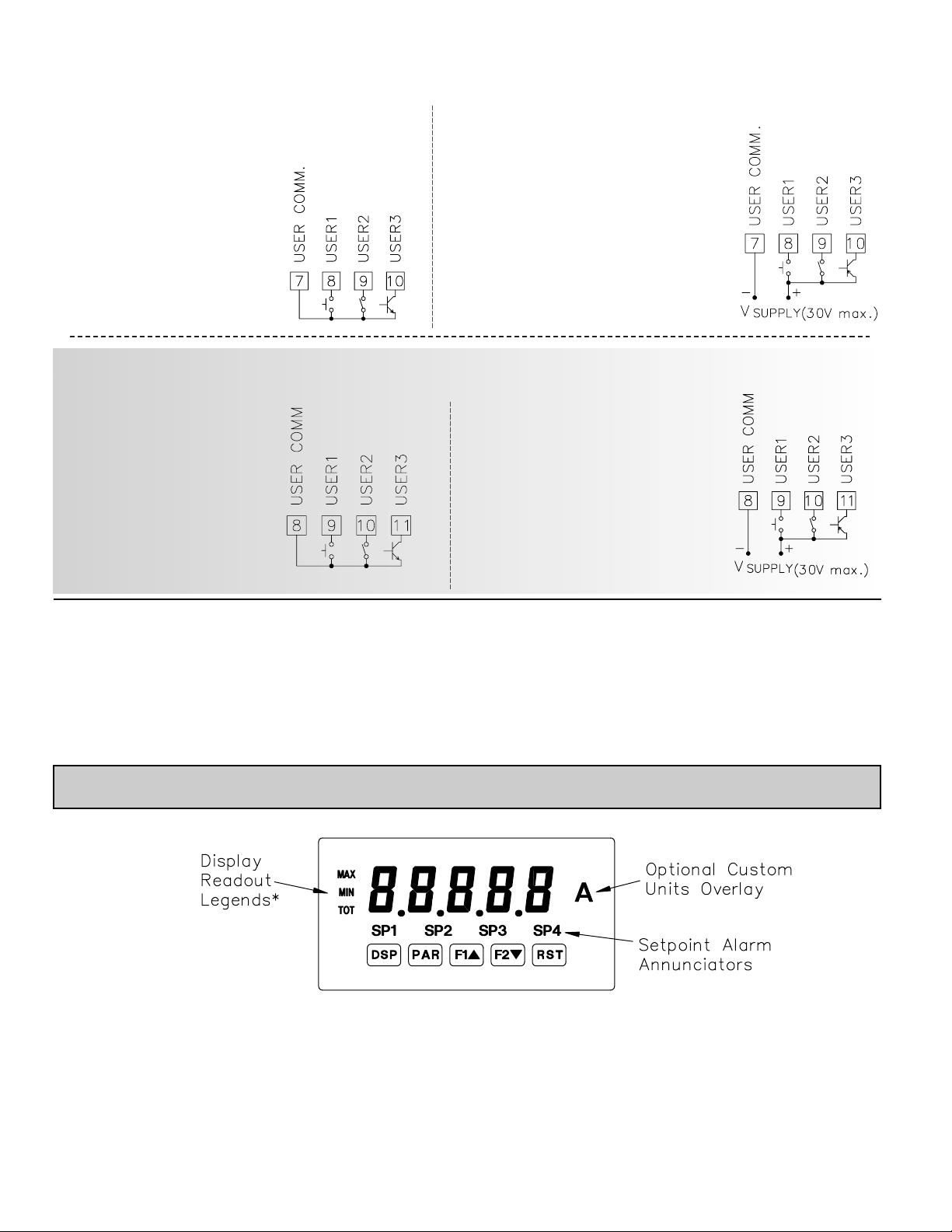
14
Sinking Logic
Terminal 8-10:
Terminal 7:
}
In this logic, the user inputs of the
meter are internally pulled up to +5 V
with 22 K resistance. The input is active
when it is pulled low (<0 .9 V).
3.3 USER INPUT WIRING
Before connecting the wires, the User Input Logic Jumper should be verified for proper position. If not using User
Inputs, then skip this section. Only the appropriate User Input terminal has to be wired.
Sourcing Logic
Terminal 8-10: + VDC thru external switching device
Terminal 7: -VDC thru external switching device
In this logic, the user inputs of the meter are
internally pulled down to 0 V with 22 K
resistance. The input is active when a voltage
greater than 3.6 VDC is applied.
Connect external switching device between
appropriate User Input terminal and User Comm.
Sourcing Logic
Terminals 9-11:
+ VDC through external switching device
Terminal 8:
-VDC through external switching device
In this logic, the user inputs of the meter are
internally pulled down with 22 K resistance.
The input is active when a voltage greater
than 3.6 VDC is applied.
Sinking Logic
Terminals 9-11
Terminal 8
In this logic, the user inputs of the
meter are internally pulled up to +5 V
with 22 K resistance. The input is
active when it is pulled low (<0 .9 V).
Connect external
switching device between
appropriate User Input
terminal and User Comm.
}
DP63700 ONLY
* Display Readout Legends may be locked out in Factory Settings.
** Factory setting for the F1, F2, and RST keys is NO mode.
RST
F2
W
F1
V
PAR
DSP
Hold with F1V, F2Wto scroll value by x1000
Reset (Function key)**
Decrement selected parameter value
Function key 2; hold for 3 seconds for Second Function 2**
Increment selected parameter value
Function key 1; hold for 3 seconds for Second Function 1**
Store selected parameter and index to next parameterAccess parameter list
Quit programming and return to display modeIndex display through max/min/total/input readouts
PROGRAMMING MODE OPERATIONDISPLAY MODE OPERATION
4.0 R
EVIEWING THE FRONT BUTTONS AND DISPLAY
3.4 SETPOINT (ALARMS) WIRING
3.5 SERIAL COMMUNICATION WIRING
3.6 ANALOG OUTPUT WIRING
⎫⎫
⎬⎬
⎭⎭
See appropriate plug-in card bulletin for details.
BUTTON
Page 15
15
OVERVIEW
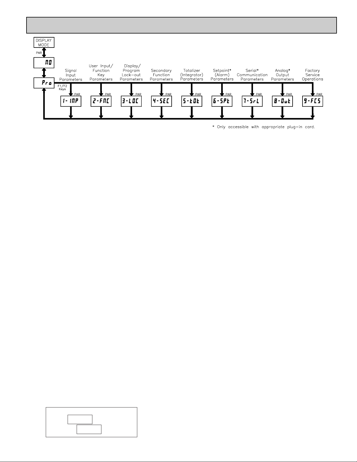
PROGRAMMING MENU
5.0 PROGRAMMING THE METER
DISPLAY MODE
The meter normally operates in the Display Mode. In this mode, the meter
displays can be viewed consecutively by pressing the
DSP key. The
annunciators to the left of the display indicate which display is currently shown;
Max Value (MAX), Min Value (MIN), or Totalizer Value (TOT). Each of these
displays can be locked from view through programming. (See Module 3) The
Input Display Value is shown with no annunciator.
PROGRAMMING MODE
Two programming modes are available.
Full Programming Mode permits all parameters to be viewed and modified.
Upon entering this mode, the front panel keys change to Programming Mode
operations. This mode should not be entered while a process is running, since
the meter functions and User Input response may not operate properly while
in Full Programming Mode.
Quick Programming Mode permits only certain parameters to be viewed
and/or modified. When entering this mode, the front panel keys change to
Programming Mode operations, and all meter functions continue to operate
properly. Quick Programming Mode is configured in Module 3. The Display
Intensity Level “” parameter is available in the Quick Programming
Mode only when the security code is non-zero. For a description, see Module
9—Factory Service Operations. Throughout this document, Programming
Mode (without Quick in front) always refers to “Full” Programming Mode.
PROGRAMMING TIPS
The Programming Menu is organized into nine modules (See above). These
modules group together parameters that are related in function. It is
recommended to begin programming with Module 1 and proceed through each
module in sequence. Note that Modules 6 through 8 are only accessible when
the appropriate plug-in option card is installed. If lost or confused while
programming, press the
DSP key to exit programming mode and start over.
When programming is complete, it is recommended to record the meter settings
on the Parameter Value Chart and lock-out parameter programming with a User
Input or lock-out code. (See Modules 2 and 3 for lock-out details.)
FACTORY SETTINGS
Factory Settings may be completely restored in Module 9. This is a good
starting point if encountering programming problems. Throughout the module
description sections which follow, the factory setting for each parameter is
shown below the parameter display. In addition, all factory settings are listed on
the Parameter Value Chart following the programming section.
ALTERNATING SELECTION DISPLAY
In the module description sections which follow, the dual display with
arrows appears for each programming parameter. This is used to illustrate the
display alternating between the parameter (top display) and the parameter's
Factory Setting (bottom display). In most cases, selections or value ranges for
the parameter will be listed on the right.
Indicates Program Mode Alternating Display
Parameter
Selection/Value
ª
«
STEP BY STEP PROGRAMMING INSTRUCTIONS:
PROGRAMMING MODE ENTRY (PAR KEY)
The Programming Mode is entered by pressing the PAR key. If this mode is
not accessible, then meter programming is locked by either a security code or a
hardware lock. (See Modules 2 and 3 for programming lock-out details.)
MODULE ENTRY (ARROW & PAR KEYS)
Upon entering the Programming Mode, the display alternates between
and the present module (initially ). The arrow keys (
F1S and F2T) are used
to select the desired module, which is then entered by pressing the
PAR key.
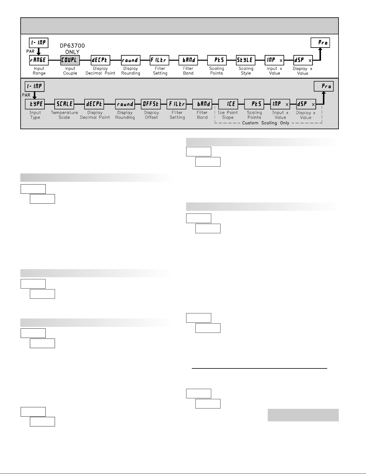
PARAMETER (MODULE) MENU (PAR KEY)
Each module has a separate parameter menu. These menus are shown at the
start of each module description section which follows. The
PAR key is pressed
to advance to a particular parameter to be changed, without changing the
programming of preceding parameters. After completing a module, the display
will return to . From this point, programming may continue by selecting
and entering additional modules. (See MODULE ENTRY above.)
PARAMETER SELECTION ENTRY (ARROW & PAR KEYS)
For each parameter, the display alternates between the parameter and the
present selection or value for that parameter. For parameters which have a list
of selections, the arrow keys (
F1S and F2T) are used to sequence through the
list until the desired selection is displayed. Pressing the
PAR key stores and
activates the displayed selection, and also advances the meter to the next
parameter.
NUMERICAL VALUE ENTRY (ARROW, RST & PAR KEYS)
For parameters which require a numerical value entry, the arrow keys can be
used to increment or decrement the display to the desired value. When an arrow
key is pressed and held, the display automatically scrolls up or scrolls down.
The longer the key is held, the faster the display scrolls.
The
RST key can be used in combination with the arrow keys to enter large
numerical values. When the
RST key is pressed along with an arrow key, the
display scrolls by 1000’s. Pressing the
PAR key stores and activates the
displayed value, and also advances the meter to the next parameter.
PROGRAMMING MODE EXIT (DSP KEYor P AR KEYat )
The Programming Mode is exited by pressing the DSP key (from anywhere
in the Programming Mode) or the
PAR key (with displayed). This will
commit any stored parameter changes to memory and return the meter to the
Display Mode. If a parameter was just changed, the
PAR key should be pressed
to store the change before pressing the
DSP key. (If power loss occurs before
returning to the Display Mode, verify recent parameter changes.)
Page 16
16
5.1 MODULE 1 - SIGNAL INPUT
PARAMETERS (
)
ª
«
ª
«
DP63700 INPUT RANGE
DP63700 INPUT COUPLE
Select the input range that corresponds to the external signal. This selection
should be high enough to avoid input signal overload but low enough for the
desired input resolution. This selection and the position of the Input Range
Jumper must match.
The input signal can be either AC coupled (rejecting the DC components of
the signal) or DC coupled (measures both the AC and DC components of the
signal). The coupling jumper and the setting of this parameter must match.
dC
or
AC
SELECTION
RANGE
RESOLUTION
5.000 A
200.00 mA
20.000 mA
2.0000 mA
200.00 µA
200uA
RANGE
RESOLUTION
SELECTION
300.0 V
20.000 V
2.0000 V
200.00 mV
0.2u
DP63500 PARAMETER MENU
ª
«
DP63600 INPUT RANGE
Select the input range that corresponds to the external signal. This selection
should be high enough to avoid input signal overload but low enough for the
desired input resolution. This selection and the position of the Input Range
Jumper must match.
1000o
10000 ohm
1000.0 ohm
±200.00 mV
±2.0000 A
2A
SELECTION
RANGE
RESOLUTION
RANGE
RESOLUTION
SELECTION
100o
300u
100.00 ohm
±300.00 V
±200.00 mA
20u
2u
±20.000 V
±2.0000 V
±20.000 mA
±2.0000 mA
±200.00 µA
200uA
Refer to the appropriate Input Range for the selected
meter. Use only one Input Range, then proceed to Display
Decimal Point.
ª
«
DP63800 INPUT RANGE
Select the input range that corresponds to the external signal.
10.000 V
20.000 mA
RANGE
RESOLUTION
SELECTION
ª
«
DP63900 INPUT RANGE
Select the input range that corresponds to the external signal. This selection
should be high enough to avoid input signal overload but low enough for the
desired input resolution. This selection and the position of the Input Range
Jumper must match.
RANGE
RESOLUTION
0.02u
SELECTION
±24 mV
±240 mV
ª
«
DP63500 INPUT TYPE
Select the input type that corresponds to the input sensor. For RTD types,
check the RTD Input Jumper for matching selection. For custom types, the
Temperature Scale parameter is not available, the Display Decimal Point is
expanded, and Custom Sensor Scaling must be completed.
CS-rH
Custom RTD Low
Custom RTD High
N TC
B TC
Cu427
Custom TC
RTD copper 10 Ω
S TC
R TC
SELECTION TYPETYPESELECTION
Ni672
Pt392
RTD nickel 672
RTD platinum 392
K TC
Pt385
RTD platinum 385
C TC
J TC
E TC
TTC
tc-t
ª
«
DP63500 TEMPERATURE SCALE
Select the temperature scale. This selection applies for Input, MAX, MIN,
and TOT displays. This does not change the user installed Custom Units
Overlay display. If changed, those parameters that relate to the temperature
scale should be checked. This selection is not available for custom sensor types.
°C°F
ª
«
0.000 0.00000.000.00
DISPLAY DECIMAL POINT
Select the decimal point location for the Input, MAX and MIN displays. (The
TOT display decimal point is a separate parameter.) This selection also affects
, and parameters and setpoint values.
For the DP63500, these are only
available with Custom Scaling.
⎫
⎬
⎭
DP63x00 PARAMETER MENU
Page 17

17
DP63500: ICE POINT SLOPE
DP63500: TEMPERATURE DISPLAY OFFSET*
ª
«
DISPLAY ROUNDING*
100502010
521
Rounding selections other than one, cause the Input Display to ‘round’to the
nearest rounding increment selected (ie. rounding of ‘5’ causes 122 to round to
120 and 123 to round to 125). Rounding starts at the least significant digit of
the Input Display. Remaining parameter entries (scaling point values, setpoint
values, etc.) are not automatically adjusted to this display rounding selection.
ª
«
The temperature display can be corrected with an offset value. This can be
used to compensate for probe errors, errors due to variances in probe placement
or adjusting the readout to a reference thermometer. This value is automatically
updated after a Zero Display to show how far the display is offset. Avalue of
zero will remove the affects of offset.
to
ª
«
FILTER SETTING*
The input filter setting is a time constant expressed in tenths of a second. The
filter settles to 99% of the final display value within approximately 3 time
constants. This is an Adaptive Digital Filter which is designed to steady the
Input Display reading. Avalue of ‘0’ disables filtering.
to seconds
ª
«
FILTER BAND*
The digital filter will adapt to variations in the input signal. When the
variation exceeds the input filter band value, the digital filter disengages. When
the variation becomes less than the band value, the filter engages again. This
allows for a stable readout, but permits the display to settle rapidly after a large
process change. The value of the band is in display units. Aband setting of ‘0’
keeps the digital filter permanently engaged.
to display units
* Factory Setting can be used without affecting basic start-up.
ª
«
This parameter sets the slope value for ice point compensation for the
Custom TC range (
) only. The fixed thermocouple ranges are
automatically compensated by the meter and do not require this setting. To
calculate this slope, use μV data obtained from thermocouple manufacturers’
tables for two points between 0°C and 50°C. Place this corresponding μV and
°C information into the equation:
slope = (μV
2
- μV1)/(°C2- °C1).
Due to the nonlinear output of thermocouples, the compensation may show
a small offset error at room temperatures. This can be compensated by the offset
parameter. A value of 0 disables internal compensation when the thermocouple
is externally compensated.
to μV/°C
For the DP63500, the following parameters only apply to
Custom Sensor Scaling.
ª
«
SCALING POINTS*
Linear - Scaling Points (2)
For linear processes, only 2 scaling points are necessary. It is recommended
that the 2 scaling points be at opposite ends of the input signal being applied.
The points do not have to be the signal limits. Display scaling will be linear
between and continue past the entered points up to the limits of the Input Signal
Jumper position. Each scaling point has a coordinate-pair of Input Value (
)
and an associated desired Display Value (
).
Nonlinear - Scaling Points (Greater than 2)
For non-linear processes, up to 16 scaling points may be used to provide a
piece-wise linear approximation. (The greater the number of scaling points
used, the greater the conformity accuracy.) The Input Display will be linear
between scaling points that are sequential in program order. Each scaling point
has a coordinate-pair of Input Value (
) and an associated desired Display
Value (
). Data from tables or equations, or empirical data could be used to
derive the required number of segments and data values for the coordinate pairs.
to
ª
«
SCALING STYLE
If Input Values and corresponding Display Values are known, the Key-in
(
) scaling style can be used. This allows scaling without the presence or
changing of the input signal. If Input Values have to be derived from the actual
input signal source or simulator, the Apply (
) scaling style must be used.
After using
scaling style, this parameter will default back to , but the
scaling values will be shown from the previous applied method.
This parameter does not apply for the DP63500. Scaling values for the
DP63500 must be keyed-in.
ª
«
INPUT VALUE FOR SCALING POINT 1
For Key-in (), enter the known first Input Value by using the arrow keys.
(The Input Range selection sets up the decimal location for the Input Value).
For Apply (
), apply the input signal to the meter, adjust the signal source
externally until the desired Input Value appears. In either method, press the
PAR key to enter the value being displayed.
to
ª
«
DISPLAY VALUE FOR SCALING POINT 1
to
Enter the first coordinating Display Value by using the arrow keys. This is
the same for
and scaling styles. The decimal point follows the
selection.
ª
«
INPUT VALUE FOR SCALING POINT 2
to
For Key-in (), enter the known second Input Value by using the arrow
keys. For Apply (
), adjust the signal source externally until the next
desired Input Value appears. (Follow the same procedure if using more than 2
scaling points.)
These bottom selections are not
available for the DP63500.
⎫
⎬
⎭
Note: style - Pressing the RST key will advance the display to the next
scaling display point without storing the input value.
KEY
key-in data
APLY
apply signal
Page 18
18
ª
«
DISPLAY VALUE FOR SCALING POINT 2
to
General Notes on Scaling
1. Input Values for scaling points should be confined to the limits of the Input
Range Jumper position.
2. The same Input Value should not correspond to more than one Display V alue.
(Example: 20 mA can not equal 0 and 10.)
This is referred to as read out jumps (vertical scaled segments).
3. The same Display Value can correspond to more than one Input Value.
(Example: 0 mA and 20 mA can equal 10.)
This is referred to as readout dead zones (horizontal scaled segments).
4. The maximum scaled Display Value spread between range maximum and
minimum is limited to 65,535. For example using +20 mA range the
maximum +20 mAcan be scaled to is 32,767 with 0 mA being 0 and Display
Rounding of 1. (Decimal points are ignored.) The other half of 65,535 is for
the lower half of the range 0 to -20 mA even if it is not used. With Display
Rounding of 2, +20 mA can be scaled for 65,535 (32,767 x 2) but with even
Input Display values shown.
5. For input levels beyond the first programmed Input Value, the meter extends
the Display Value by calculating the slope from the first two coordinate pairs
(
/ & / ). If = 4 mA and = 0, then 0 mA
would be some negative Display Value. This could be prevented by making
= 0 mA / = 0, = 4 mA / = 0, with = 20 mA /
= the desired high Display Value. The calculations stop at the limits of
the Input Range Jumper position.
6. For input levels beyond the last programmed Input Value, the meter extends
the Display Value by calculating the slope from the last two sequential
coordinate pairs. If three coordinate pair scaling points were entered, then the
Display Value calculation would be between
/ & / .
The calculations stop at the limits of the Input Range Jumper position.
Enter the second coordinating Display Value by using the arrow keys. This is
the same for
and scaling styles. (Follow the same procedure if using
more than 2 scaling points.)
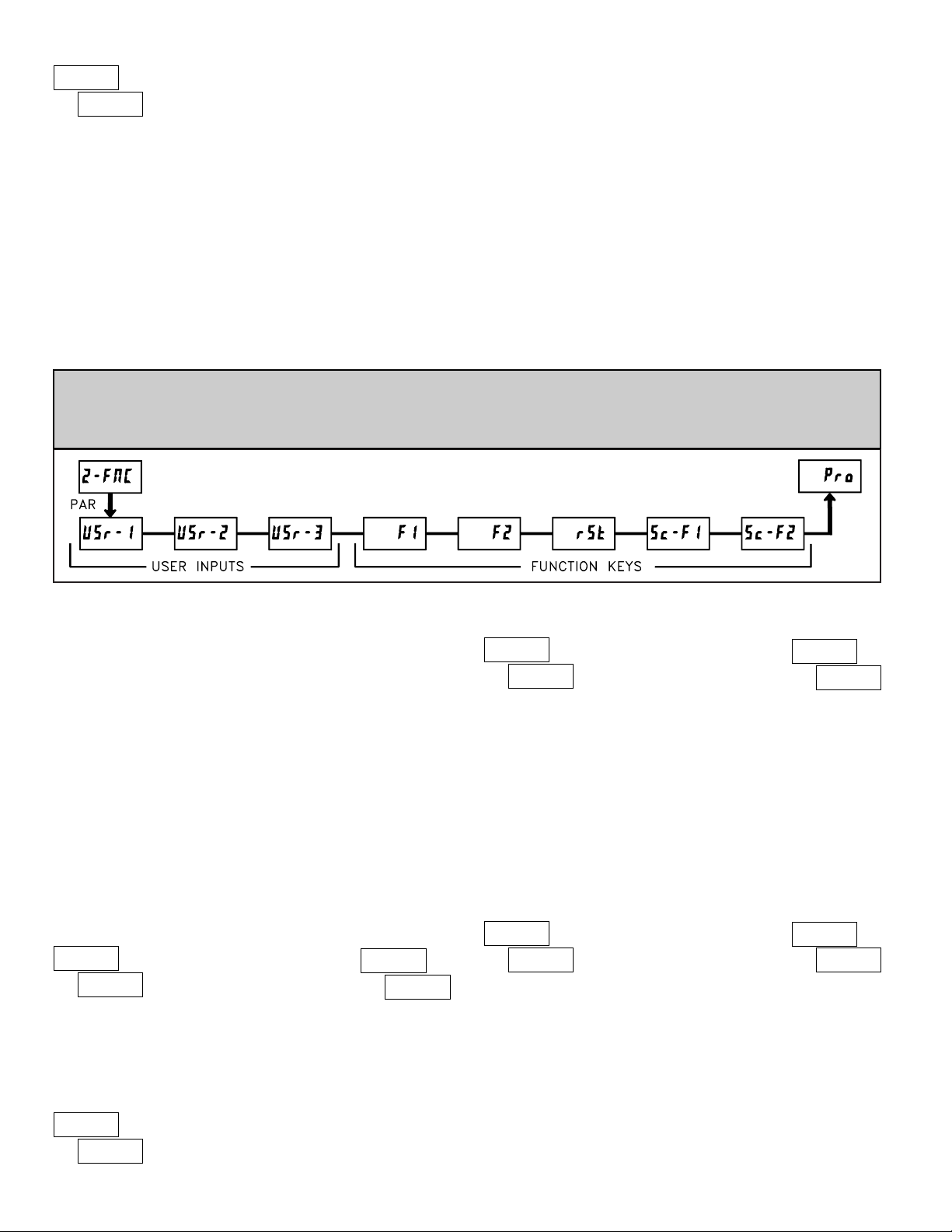
5.2 MODULE 2 - USER INPUT AND FRONT PANEL FUNCTION KEY
PARAMETERS ()
PARAMETER MENU
The three user inputs are individually programmable to perform specific
meter control functions. While in the Display Mode or Program Mode, the
function is executed the instant the user input transitions to the active state.
The front panel function keys are also individually programmable to perform
specific meter control functions. While in the Display Mode, the primary
function is executed the instant the key is pressed. Holding the function key for
three seconds executes a secondary function. It is possible to program a
secondary function without a primary function.
In most cases, if more than one user input and/or function key is programmed
for the same function, the maintained (level trigger) actions will be performed
while at least one of those user inputs or function keys are activated. The
momentary (edge trigger) actions will be performed every time any of those
user inputs or function keys transition to the active state.
Note: In the following explanations, not all selections are available for both
user inputs and front panel function keys. Alternating displays are shown
with each selection. Those selections showing both displays are available for
both. If a display is not shown, it is not available for that selection.
will represent all three user inputs. will represent all five function keys.
ª
«
ª
«
NO FUNCTION
No function is performed if activated. This is the factory setting for all user
inputs and function keys. No function can be selected without affecting basic
start-up.
ª
«
PROGRAMMING MODE LOCK-OUT
Programming Mode is locked-out, as long as activated
(maintained action). A security code can be configured to
allow programming access during lock-out.
ZERO (TARE) DISPLAY
ª
«
ª
«
The Zero (Tare) Display provides a way to zero the Input Display value at
various input levels, causing future Display readings to be offset. This function
is useful in weighing applications where the container or material on the scale
should not be included in the next measurement value. When activated
(momentary action),
flashes and the Display is set to zero. At the same
time, the Display value (that was on the display before the Zero Display) is
subtracted from the Display Offset Value and is automatically stored as the new
Display Offset Value (
). If another Zero (tare) Display is performed, the
display will again change to zero and the Display reading will shift accordingly.
ª
«
ª
«
RELATIVE/ABSOLUTE DISPLAY
This function will switch the Input Display between Relative and Absolute.
The Relative is a net value that includes the Display Offset Value. The Input
Display will normally show the Relative unless switched by this function.
Regardless of the display selected, all meter functions continue to operate based
on relative values. The Absolute is a gross value (based on Module 1 DSPand
INP entries) without the Display Offset Value. The Absolute display is selected
as long as the user input is activated (maintained action) or at the transition of
the function key (momentary action). When the user input is released, or the
function key is pressed again, the input display switches back to Relative
display.
(absolute) or (relative) is momentarily displayed at transition
to indicate which display is active.
Page 19

19
ª
«
HOLD DISPLAY
The shown display is held but all other meter functions
continue as long as activated (maintained action).
ª
«
HOLD ALL FUNCTIONS
The meter disables processing the input, holds all display
contents, and locks the state of all outputs as long as activated
(maintained action). The serial port continues data transfer.
ª
«
SYNCHRONIZE METER READING
The meter suspends all functions as long as activated
(maintained action). When the user input is released, the
meter synchronizes the restart of the A/D with other
processes or timing events.
ª
«
ª
«
STORE BATCH READING IN TOTALIZER
The Input Display value is one time added (batched) to the Totalizer at
transition to activate (momentary action). The Totalizer retains a running sum of
each batch operation until the Totalizer is reset. When this function is selected,
the normal operation of the Totalizer is overridden.
ª
«
SELECT TOTALIZER DISPLAY
The Totalizer display is selected as long as activated
(maintained action). When the user input is released, the
Input Display is returned. The DSP key overrides the active
user input. The Totalizer continues to function including
associated outputs independent of being displayed.
ª
«
ª
«
RESET TOTALIZER
When activated (momentary action), flashes and the T otalizer resets to
zero. The Totalizer then continues to operate as it is configured. This selection
functions independent of the selected display.
ª
«
RESET AND ENABLE TOTALIZER
When activated (momentary action), flashes and
the Totalizer resets to zero. The Totalizer continues to
operate while active (maintained action). When the user
input is released, the T otalizer stops and holds its value. This
selection functions independent of the selected display.
ª
«
ENABLE TOTALIZER
The Totalizer continues to operate as long as activated
(maintained action). When the user input is released, the
Totalizer stops and holds its value. This selection functions
independent of the selected display.
ª
«
SELECT MAXIMUM DISPLAY
The Maximum display is selected as long as activated
(maintained action). When the user input is released, the
Input Display returns. The DSP key overrides the active
user input. The Maximum continues to function
independent of being displayed.
ª
«
RESET MAXIMUM
When activated (momentary action), flashes and
the Maximum resets to the present Input Display value. The
Maximum function then continues from that value. This
selection functions independent of the selected display.
ª
«
RESET, SELECT, ENABLE MAXIMUM DISPLAY
When activated (momentary action), the Maximum value
is set to the present Input Display value. Maximum continues
from that value while active (maintained action). When the
user input is released, Maximum detection stops and holds its
ª
«
SELECT MINIMUM DISPLAY
The Minimum display is selected as long as activated
(maintained action). When the user input is released, the
Input Display is returned. The DSPkey overrides the active
user input. The Minimum continues to function
independent of being displayed.
RESET MINIMUM
ª
«
When activated (momentary action), flashes and
the Minimum reading is set to the present Input Display
value. The Minimum function then continues from that value.
This selection functions independent of the selected display.
ª
«
RESET, SELECT, ENABLE MINIMUM DISPLAY
When activated (momentary action), the Minimum value
is set to the present Input Display value. Minimum continues
from that value while active (maintained action). When the
user input is released, Minimum detection stops and holds
ª
«
ª
«
RESET MAXIMUM AND MINIMUM
When activated (momentary action), flashes and the Maximum and
Minimum readings are set to the present Input Display value. The Maximum and
Minimum function then continues from that value. This selection functions
independent of the selected display.
ª
«
ª
«
CHANGE DISPLAY INTENSITY LEVEL
When activated (momentary action), the display intensity changes to the next
intensity level (of 4). The four levels correspond to Display Intensity Level (
) settings of 0, 3, 8, and 15. The intensity level, when changed via the User
Input/ Function Key, is not retained at power-down, unless Quick Programming
or Full Programming mode is entered and exited. The meter will power-up at the
last saved intensity level.
its value. This selection functions independent of the selected display . The DSP
key overrides the active user input display but not the Minimum function.
value. This selection functions independent of the selected display. The DSP key
overrides the active user input display but not the Maximum function.
Page 20
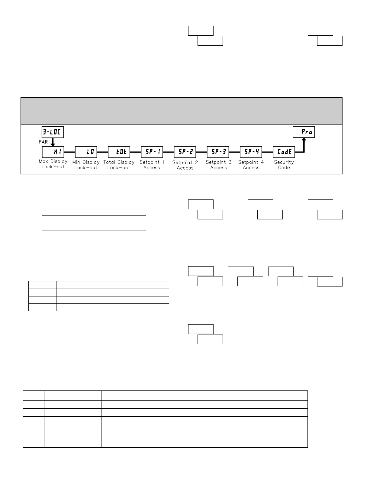
20
SETPOINT SELECTIONS
- Select main or alternate setpoints
- Reset Setpoint 1 (Alarm 1)
- Reset Setpoint 2 (Alarm 2)
- Reset Setpoint 3 (Alarm 3)
- Reset Setpoint 4 (Alarm 4)
- Reset Setpoint 3 & 4 (Alarm 3 & 4)
- Reset Setpoint 2, 3 & 4 (Alarm 2, 3 & 4)
- Reset Setpoint All (Alarm All)
The following selections are accessible only with the Setpoint plug-in card
installed. Refer to the Setpoint Card Bulletin shipped with the Setpoint plug-in
card for an explanation of their operation.
Setpoint
Card
Only
ª
«
ª
«
PRINT REQUEST
The meter issues a block print through the serial port when activated. The
data transmitted during a print request is programmed in Module 7. If the user
input is still active after the transmission is complete (about 100 msec), an
additional transmission occurs. As long as the user input is held active,
continuous transmissions occur.
ª
«
PROGRAM MODE SECURITY CODE*
By entering any non-zero value, the prompt will appear when trying
to access the Program Mode. Access will only be allowed after entering a
matching security code or universal code of
. With this lock-out, a user input
would not have to be configured for Program Lock-out. However, this lock-out
is overridden by an inactive user input configured for Program Lock-out.
ª
«
ª
«
ª
«
ª
«
SP-1 SP-2 SP-3 SP-4 SETPOINT ACCESS*
The setpoint displays can be programmed for , or (See the
following table). Accessible only with the Setpoint plug-in card installed.
ª
«
ª
«
ª
«
MAXIMUM DISPLAY LOCK-OUT*
MINIMUM DISPLAY LOCK-OUT*
TOTALIZER DISPLAY LOCK-OUT*
These displays can be programmed for or . When programmed for
, the display will not be shown when the DSP key is pressed regardless of
Program Lock-out status. It is suggested to lock-out the display if it is not needed.
The associated function will continue to operate even if its display is locked-out.
5.3 MODULE 3 - DISPLAY AND
PROGRAM LOCK-OUT
PARAMETERS ()
PARAMETER MENU
* Factory Setting can be used without affecting basic start-up.
to
Module 3 is the programming for Display lock-out and “Full” and “Quick”
Program lock-out.
When in the Display Mode, the available displays can be read consecutively
by repeatedly pressing the DSP key. An annunciator indicates the display being
shown. These displays can be locked from being visible. It is recommended that
the display be set to
when the corresponding function is not used.
“Full” Programming Mode permits all parameters to be viewed and
modified. This Programming Mode can be locked with a security code and/or
user input. When locked and the PAR key is pressed, the meter enters a Quick
Programming Mode. In this mode, the setpoint values can still be read and/or
changed per the selections below. The Display Intensity Level ()
parameter also appears whenever Quick Programming Mode is enabled and the
security code is greater than zero.
SELECTION DESCRIPTION
Visible but not changeable in Quick Programming Mode
Visible and changeable in Quick Programming Mode
Not visible in Quick Programming Mode
Immediate access.“Full” ProgrammingNot Active
0
No accessQuick ProgrammingActive
0
Immediate access.“Full” ProgrammingNot Active
>0
After Quick Programming with correct code # at prompt.Quick Programming w/Display IntensityActive
>0
After Quick Programming with correct code # at prompt.Quick Programming w/Display Intensity————
not
>0
Immediate access.“Full” Programming————
not
0
“FULL” PROGRAMMING MODE ACCESS
WHEN PAR KEY IS
PRESSED
USER INPUT
STATE
USER INPUT
CONFIGURED
SECURITY
CODE
PROGRAMMING MODE ACCESS
Throughout this document, Programming Mode (without Quick in front) always refers to “Full” Programming (all meter parameters are accessible).
SELECTION DESCRIPTION
Visible in Display Mode
Not visible in Display Mode
⎧
⎨
⎩
Page 21
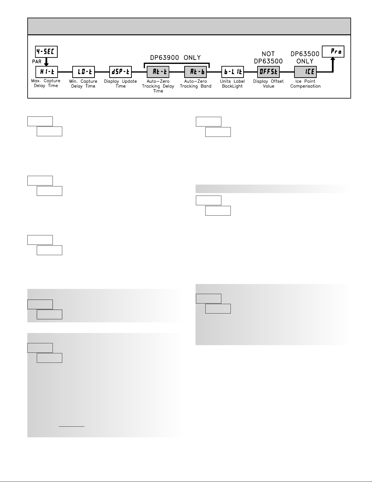
21
ª
«
MAX CAPTURE DELAY TIME*
When the Input Display is above the present MAX value for the entered
delay time, the meter will capture that display value as the new MAX reading.
A delay time helps to avoid false captures of sudden short spikes.
ª
«
MIN CAPTURE DELAY TIME*
When the Input Display is below the present MIN value for the entered delay
time, the meter will capture that display value as the new MIN reading. Adelay
time helps to avoid false captures of sudden short spikes.
ª
«
UNITS LABEL BACKLIGHT*
The Units Label Kit Accessory contains a sheet of custom unit overlays
which can be installed in to the meter’s bezel display assembly. The backlight
for these custom units is activated by this parameter.
ª
«
DISPLAY OFFSET VALUE*
Unless a Zero Display was performed or an offset from Module 1 scaling is
desired, this parameter can be skipped. The Display Offset Value is the
difference from the Absolute (gross) Display value to the Relative (net) Display
value for the same input level. The meter will automatically update this Display
Offset Value after each Zero Display. The Display Offset Value can be directly
keyed-in to intentionally add or remove display offset. See Relative / Absolute
Display and Zero Display explanations in Module 2.
ª
«
DISPLAY UPDATE RATE*
This parameter determines the rate of display update. When set to 20
updates/second, the internal re-zero compensation is disabled, allowing for the
fastest possible output response.
5.4 MODULE 4 - SECONDARY FUNCTION PARAMETERS ()
PARAMETER MENU
* Factory Setting can be used without affecting basic start-up.
to sec.
to sec.
to
updates/sec.
ª
«
DP63900: AUTO-ZERO TRACKING
to sec.
ª
«
DP63900: AUTO-ZERO BAND
to
The meter can be programmed to automatically compensate for zero drift.
Drift may be caused by changes in the transducers or electronics, or
accumulation of material on weight systems.
Auto-zero tracking operates when the readout remains within the tracking
band for a period of time equal to the tracking delay time. When these
conditions are met, the meter re-zeroes the readout. After the re-zero operation,
the meter resets and continues to auto-zero track.
The auto-zero tracking band should be set large enough to track normal zero
drift, but small enough to not interfere with small process inputs.
For filling operations, the fill rate must exceed the auto-zero tracking rate.
This avoids false tracking at the start of the filling operation.
Fill Rate ≥ tracking band
tracking time
Auto-zero tracking is disabled by setting the auto-zero tracking parameter = 0.
ª
«
DP63500: ICE POINT COMPENSATION*
This parameter turns the internal ice point compensation on or off. Normally,
the ice point compensation is on. If using external compensation, set this
parameter to off. In this case, use copper leads from the external compensation
point to the meter. If using Custom TC range, the ice point compensation can
be adjusted by a value in Module 1 when this is yes.
This parameter does not apply for the DP63500.
Page 22
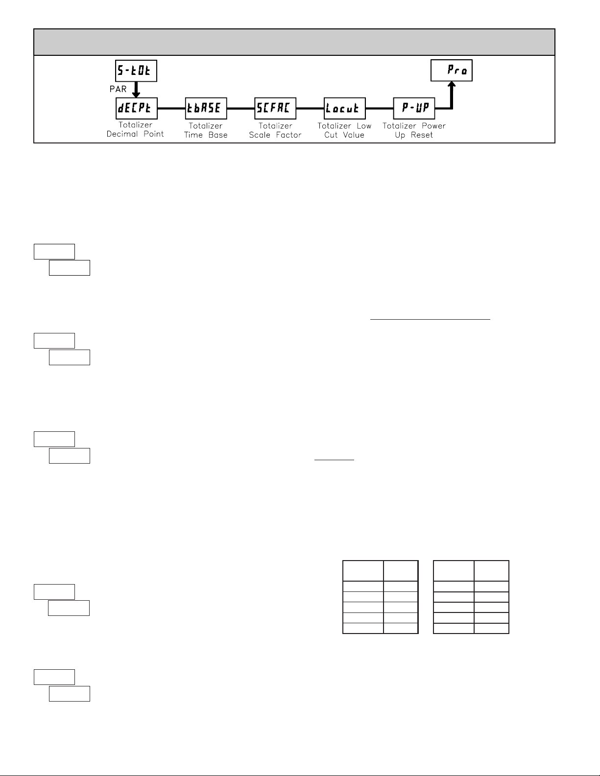
22
* Factory Setting can be used without affecting basic start-up.
5.5 MODULE 5 - TOTALIZER (INTEGRATOR
) PARAMETERS (
)
PARAMETER MENU
ª
«
TOTALIZER DECIMAL POINT*
For most applications, this matches the Input Display Decimal Point
(
). If a different location is desired, refer to Totalizer Scale Factor.
0.000 0.00000.000.00
ª
«
TOTALIZER TIME BASE
This is the time base used in T otalizer accumulations. If the Totalizer is being
accumulated through a user input programmed for Batch, then this parameter
does not apply.
ª
«
TOTALIZER SCALE FACTOR*
For most applications, the Totalizer reflects the same decimal point location
and engineering units as the Input Display. In these cases, the Totalizer Scale
Factor is 1.000. The Totalizer Scale Factor can be used to scale the Totalizer to
a different value than the Input Display. Common possibilities are:
1. Changing decimal point location (example tenths to whole)
2. Average over a controlled time frame.
Details on calculating the scale factor are shown later.
If the Totalizer is being accumulated through a user input programmed for
Batch, then this parameter does not apply.
ª
«
TOTALIZER LOW CUT VALUE*
to
to
A low cut value disables Totalizer when the Input Display value falls below
the value programmed.
ª
«
TOTALIZER POWER UP RESET*
Reset buffer
Do not reset buffer
rSt
NO
The Totalizer can be reset to zero on each meter power-up by setting this
parameter to reset.
-
seconds (÷ 1)
-
days (÷ 86400)
TOTALIZER HIGH ORDER DISPLAY
When the total exceeds 5 digits, the front panel annunciator TOT flashes. In
this case, the meter continues to totalize up to a 9 digit value. The high order 4
digits and the low order 5 digits of the total are displayed alternately. The letter
“
” denotes the high order display.
TOTALIZER BATCHING
The T otalizer Time Base and scale factor are overridden when a user input or
function key is programmed for store batch (
). In this mode, when the user
input or function key is activated, the Input Display reading is one time added
to the Totalizer (batch). The Totalizer retains a running sum of each batch
operation until the T otalizer is reset. This is useful in weighing operations, when
the value to be added is not based on time but after a filling event.
TOTALIZER USING TIME BASE
Totalizer accumulates as defined by:
Input Display x Totalizer Scale Factor
Totalizer Time Base
Where:
Input Display - the present input reading
Totalizer Scale Factor - 0.001 to 65.000
Totalizer Time Base - (the division factor of
)
Example: The input reading is at a constant rate of 10.0 gallons per minute. The
Totalizer is used to determine how many gallons in tenths has flowed.
Because the Input Display and Totalizer are both in tenths of gallons, the
Totalizer Scale Factor is 1. With gallons per minute, the Totalizer Time Base
is minutes (60). By placing these values in the equation, the Totalizer will
accumulate every second as follows:
10.0 x 1.000
= 0.1667 gallon accumulates each second
60
This results in:
10.0 gallons accumulates each minute
600.0 gallons accumulates each hour
TOTALIZER SCALE FACTOR CALCULATION EXAMPLES
1. When changing the Totalizer Decimal Point () location from the
Input Display Decimal Point (
), the required Totalizer Scale Factor is
multiplied by a power of ten.
Example: Input (
) = 0.0 Input () = 0.00
(x = Totalizer display is round by tens or hundreds)
2. To obtain an average reading within a controlled time frame, the selected
Totalizer Time Base is divided by the given time period expressed in the same
timing units.
Example: Average temperature per hour in a 4 hour period, the scale factor
would be 0.250. To achieve a controlled time frame, connect an external timer
to a user input programmed for
. The timer will control the start (reset)
and the stopping (hold) of the totalizer.
- minutes (÷ 60)
-
hours (÷ 3600)
The totalizer accumulates (integrates) the Input Display value using one of
two modes. The first is using a time base. This can be used to compute a timetemperature product. The second is through a user input or function key
programmed for Batch (one time add on demand). This can be used to provide
a readout of temperature integration, useful in curing and sterilization
applications. If the T otalizer is not needed, its display can be locked-out and this
module can be skipped during programming.
.001x10
.010
.10.0
10.00
100.000
Scale
Factor
Totalizer
Scale
Factor
0.00 10
0.0 1
0 .1
x10 .01
x100 .001
Totalizer
Page 23
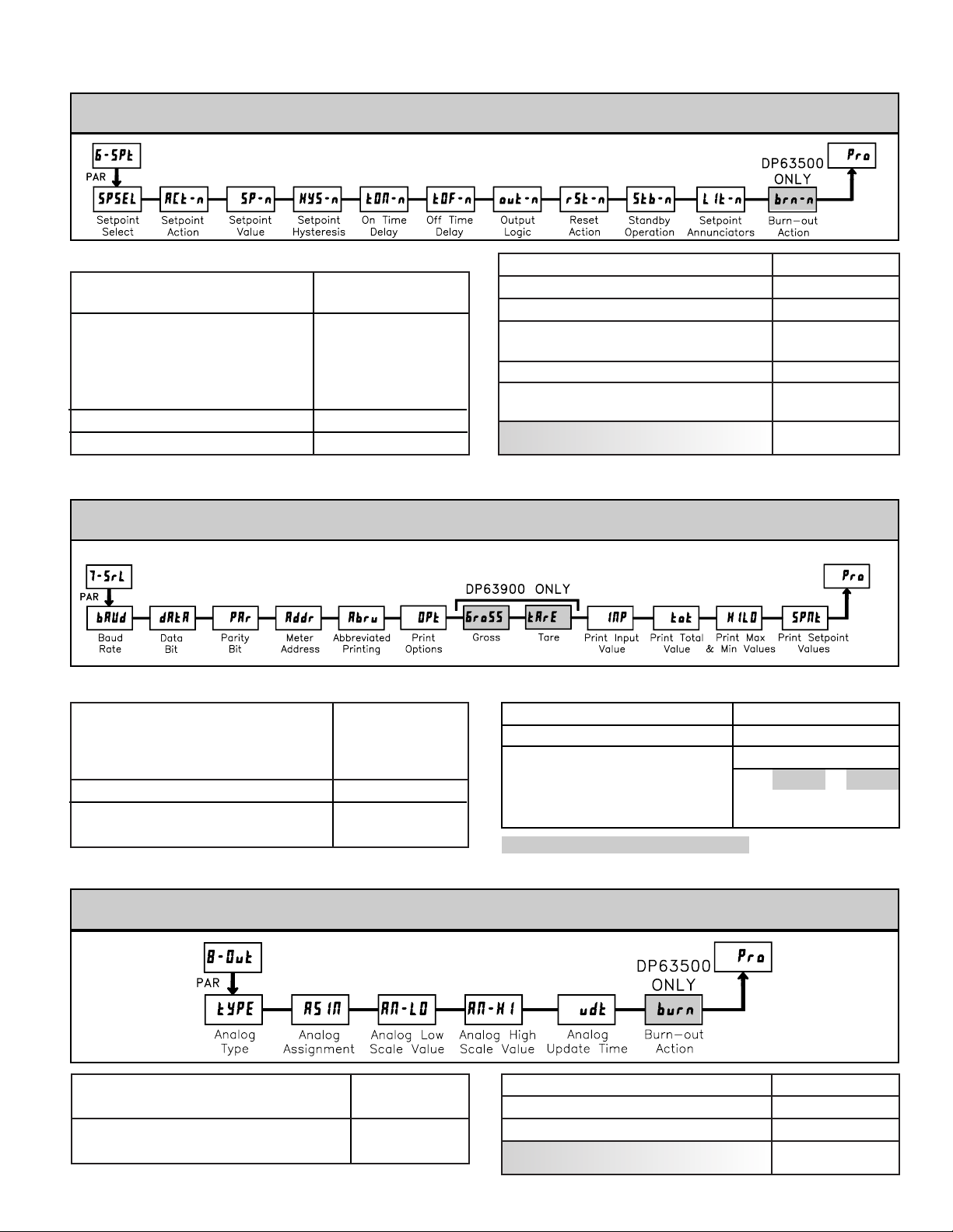
23
5.6 MODULE 6 - SETPOINT
(ALARM) PARAMETERS
(
)
PARAMETER MENU
- SELECT SETPOINT
SP-4SP-2
SP-3NO SP-1
- SETPOINT HYSTERESIS
- SETPOINT VALUE
- SETPOINT ACTION
1 to 65000
-19999 to 99999
bANdAb-LO
totHIAU-LO
dE-LOAb-HI
totLoAU-HI
dE-HIOFF
OFF
FLASH
rEv
YES
LAtC2
rEv
0.0 to 3275.0 sec
0.0 to 3275.0 sec
ON
nor
OFF
- SETPOINT ANNUNCIATORS
NO
- STANDBY OPERATION
LAtC1
AUto
- RESET ACTION
nor
- OUTPUT LOGIC
- OFF TIME DELAY
- ON TIME DELAY
5.7 MODULE 7 - SERIAL COMMUNICATIONS PARAMETERS ()
PARAMETER MENU
19200
9600
NO
8
4800
2400
1200
600
EVEN
Odd
7
- PARITY BIT
- DATA BITS
300
- BAUD RATE
YES
0 to 99
NO
SPNt
HILO
tot
INP
tArE6roSS
5.8 MODULE 8 - ANALOG OUTPUT PARAMETERS ()
PARAMETER MENU
0-10
4-20
totHI
LOINP
0-20
- ANALOG TYPE
- ANALOG ASSIGNMENT
HI LO
0.0 to 10.0 sec.
- ANALOG UPDATE TIME
- ANALOG LOW SCALE VALUE
-19999 to 99999
-19999 to 99999
Modules 6, 7, and 8 are accessible only with the appropriate plug-in cards installed. A quick overview of each Module is
listed below. Refer to the corresponding plug-in card bulletin for a more detailed explanation of each parameter selection.
This module is for RS232 and RS485.
- ANALOG HIGH SCALE VALUE
- PROBE BURN-OUT ACTION
DP63500 ONLY
- PROBE BURN-OUT ACTION
DP63500 ONLY
These two options are for the DP63900 ONLY.
- PRINT OPTIONS
- METER ADDRESS
- ABBREVIATED PRINTING
Repeat programming for each setpoint.
Page 24
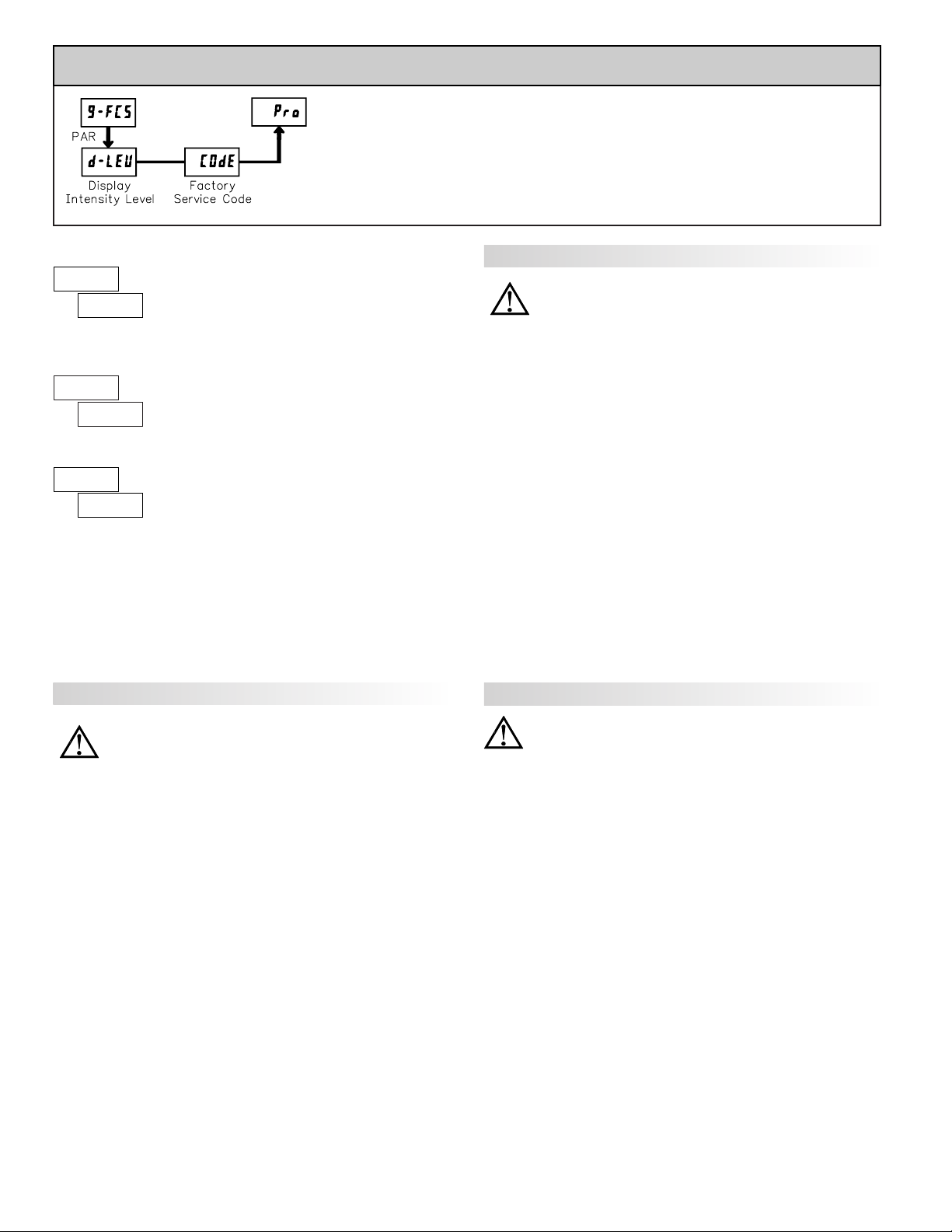
24
5.9 MODULE 9 - FACTORY SERVICE OPERATIONS ()
PARAMETER MENU
Enter the desired Display Intensity Level (0-15) by
using the arrow keys. The display will actively dim or
brighten as the levels are changed. This parameter also
appears in Quick Programming Mode when enabled.
DISPLAY INTENSITY LEVEL
ª
«
The meter has been fully calibrated at the factory.
Scaling to convert the input signal to a desired display
value is performed in Module 1. If the meter appears to be
indicating incorrectly or inaccurately, refer to
Troubleshooting before attempting to calibrate the meter.
When recalibration is required (generally every 2 years), it should only be
performed by qualified technicians using appropriate equipment. Calibration
does not change any user programmed parameters. However, it may affect the
accuracy of the input signal values previously stored using the Apply (
)
Scaling Style.
Calibration may be aborted by disconnecting power to the meter before
exiting Module 9. In this case, the existing calibration settings remain in effect.
CALIBRATION
ª
«
Before starting, verify that the Input Ranger Jumper is set for the range to be
calibrated. Also verify that the precision signal source is connected and ready.
Allow a 30 minute warm-up period before calibrating the meter.
and PAR
can be chosen to exit the calibration mode without any changes taking place.
Then perform the following procedure:
1. Use the arrow keys to display
and press PAR.
2. Choose the range to be calibrated by using the arrow keys and press PAR.
3. When the zero range limit appears on the display, apply the appropriate:
- Voltage ranges: dead short applied
- Current ranges: open circuit
- Resistance ranges: dead short with current source connected
4. Press PAR and
will appear on the display for about 10 seconds.
5. When the top range limit appears on the display, apply the appropriate:
- Voltage ranges: top range value applied (The 300 V range is the exception.
It is calibrated with a 100 V signal.)
- Current ranges: top range value
- Resistance ranges: top range value (The ohms calibration requires
connection of the internal current source through a resistance substitution
device and the proper voltage range selection.)
6. Press PAR and
will appear on the display for about 10 seconds.
7. When
appears, press PAR twice.
8. If the meter is not field scaled, then the input display should match the value
of the input signal.
9. Repeat the above procedure for each input range to be calibrated.
WARNING: Calibration of this meter requires a signal source with an
accuracy of 0.01% or better and an external meter with an accuracy
of 0.005% or better. Resistance inputs require a resistance
substitution device with an accuracy of 0.01% or better.
WARNING: Calibration of this meter requires a signal source with an
accuracy of 0.01% or better and an external meter with an accuracy
of 0.005% or better.
DP63600 - Input Calibration
DP63700 - Input Calibration
DP63800 - Input Calibration
Before starting, verify that the precision signal source is connected to the
correct terminals and ready. Allow a 30 minute warm-up period before
calibrating the meter.
and PAR can be chosen to exit the calibration mode
without any changes taking place.
Then perform the following procedure:
1. Use the arrow keys to display
and press PAR.
2. Choose the range to be calibrated by using the arrow keys and press PAR.
(
and PAR can be chosen to exit the calibration mode without any changes
taking place.)
3. When the zero range limit appears on the display, apply the appropriate:
- Voltage range: dead short applied
- Current range: open circuit
4. Press PAR and
will appear on the display for about 10 seconds.
5. When the top range limit appears on the display, apply the appropriate:
- Voltage range: 10 VDC
- Current range: 20 mADC
6. Press PAR and
will appear on the display for about 10 seconds.
7. When
appears, press PAR twice.
8. If the meter is not field scaled, then the input display should match the value
of the input signal.
9. Repeat the above procedure for each input range to be calibrated.
WARNING: In the DP63700, DC signals are used to calibrate the AC
ranges. Calibration of the DP63700 requires a DC voltmeter with an
accuracy of 0.025% and a precision DC signal source capable of:
1. +1% of full scale, DC
2. -1% of full scale, DC
3. +100% of full scale, DC; (300 V range = +100 V calibration)
4. -100% of full scale, DC; (300 V range = -100 V calibration)
Before starting, verify the Input Range and Signal Jumpers are set for the
range to be calibrated and the Couple jumper is installed for DC. Also verify the
DC signal source is connected and ready. Allow a 30 minute warm-up period
before calibrating the meter.
and PAR can be chosen to exit the calibration
mode without any changes taking place.
Then perform the following procedure:
1. Press the arrow keys to display
and press PAR.
2. The meter displays
. Use the arrow keys to select the range that matches
the Signal Jumper setting. Press PAR.
3. Apply the signal matching the meter prompt.
4. Press PAR and
will appear on the display, wait for next prompt.
5. Repeat steps 3 and 4 for the remaining three prompts.
6. When
appears, press PAR twice.
7. If the meter is scaled to show input signal, the Input Display should match
the value of the input signal in the Display Mode.
8. Repeat the above procedure for each range to be calibrated or to recalibrate
the same range. It is only necessary to calibrate the input ranges being used.
9. When all desired calibrations are completed, remove the external signal
source and restore original configuration and jumper settings. If AC is being
measured, continue with AC Couple Offset Calibration.
ª
«
RESTORE FACTORY DEFAULTS
Use the arrow keys to display and press PAR.
The meter will display
and then return to .
Press DSP key to return to Display Mode. This will
overwrite all user settings with the factory settings.
Page 25
25
It is recommended that Input Calibration be performed first.
1. With meter power removed, set the Input Range Jumper for 20 V, the Couple
Jumper for DC, and set the Signal Jumper for voltage by removing the jumper.
2. Connect a wire (short) between Volt (terminal 6) and COMM (terminal 4).
3. Apply meter power.
4. In Module 1, program as follows: Range:
; Couple: ; Decimal Point:
; Round: ; Filter: ; Band: ; Points: ; Style: ; INP1: ; DSP1:
; INP2: ; DSP2:
5. In Module 4, program as follows: Hi-t: ; Lo-t:
6. Press PAR then DSP to exit programming and view the Input Display.
7. The readout displays the DC coupled zero input, record the value.
8. Remove the meter power and set the Couple Jumper to AC by removing the
jumper.
9. Maintaining the short between terminals 4 and 6, reapply the meter power.
10. Keeping all programming the same, view the Input Display.
11. The readout now displays the AC coupled zero input, record the value.
12. In Module 9, Use the arrow keys to display
and press PAR.
13. Press the down arrow key twice to
and press PAR.
14. Calculate the offset
using the following formula:
= AC coupled reading (step 11) - DC coupled reading (step 7)
15. Use the arrow keys to enter the calculated
.
16. Press PAR three times, to exit programming.
17. Remove the meter power and remove the short from terminals 4 and 6.
18. Restore the original jumper and configuration settings.
AC Couple Offset Calibration - DP63700
DP63900 - Input Calibration
DP63500 - Input Calibration
WARNING: Calibration of this meter requires a signal source with an
accuracy of 0.01% or better and an external meter with an accuracy of
0.005% or better.
Before starting, connect -SIG (terminal 4) to COMM (terminal 5). This
allows a single ended signal to be used for calibration. Connect the calibration
signal to +SIG (terminal 3) and -SIG (terminal 4). Verify the Input Range
jumper is in the desired position. Allow a 30 minute warm-up period before
calibrating the meter.
and PAR can be chosen to exit the calibration mode
without any changes taking place. Perform the following procedure:
1. Press the arrow keys to display
and press PAR.
2. Choose the range to be calibrated by using the arrow keys and press PAR.
3. When the zero range limit appears on the display, apply 0 mVbetween +SIG
and -SIG.
4. Press PAR and ---- will appear, wait for next prompt.
5. When the top range limit appears on the display, apply the corresponding
+SIG and -SIG voltage (20 mV or 200 mV).
6. Press PAR and ---- will appear, on the display for about 10 seconds.
7. When
appears, press PAR twice to exit programming.
8. Repeat the above procedure for each range to be calibrated or to recalibrate
the same range. It is only necessary to calibrate the input ranges being used.
9. When all desired calibrations are completed, remove -SIG to COMM
connection and external signal source.
10. Restore original configuration and jumper settings.
100 OHM RTD Range Calibration
1. Set the Input Range Jumper to 100 ohm.
2. Use the arrow keys to display
and press PAR. Then choose
and press PAR.
3. At
, apply a direct short to input terminals 3, 4 and 5 using a three wire
link. Wait 10 seconds, then press PAR.
4. At
, apply a precision resistance of 300 ohms (with an accuracy of
0.01% or better) using a three wire link, to terminals 3, 4 and 5. Wait 10
seconds, press PAR.
5. Connect the RTD, return to the Display Mode and verify the input reading
(with 0 Display Offset) is correct. If not correct repeat calibration.
THERMOCOUPLE Range Calibration
1. Use the arrow keys to display and press PAR. Then choose and
press PAR.
2. At
, apply a dead short or set calibrator to zero to input terminals 4 and
5. Wait 10 seconds, then press PAR.
3. At
, apply 50.000 mV input signal (with an accuracy of 0.01% or
better) to input terminals 4 and 5. Wait 10 seconds, then press PAR.
4. Return to the Display Mode.
5. Continue with Ice Point Calibration.
ICE POINT Calibration
1. Remove all option cards or invalid results will occur.
2. The ambient temperature must be within 20°C to 30°C.
3. Connect a thermocouple (types T , E, J, K, or N only) with an accuracy of 1 °C
or better to the meter.
4. Verify the readout Display Offset is 0, Temperature Scale is °C, Display
Resolution is 0.0, and the Input Range is set for the connected thermocouple.
5. Place the thermocouple in close thermal contact to a reference thermometer
probe. (Use a reference thermometer with an accuracy of 0.25°C or better.)
The two probes should be shielded from air movement and allowed sufficient
time to equalize in temperature. (A calibration bath could be used in place of
the thermometer.)
6. In the Normal Display mode, compare the readouts.
7. If a difference exists then continue with the calibration.
8. Enter Module 9, use the arrow keys to display
and press PAR. Then
choose and press PAR.
9. Calculate a new Ice Point value using: existing Ice Point value + (reference
temperature - Display Mode reading). All values are based on °C.
10. Enter the new Ice Point value.
11. Return to the Display Mode and verify the input reading (with 0 Display
Offset) is correct. If not correct repeat steps 8 through 10.
Warning: Calibration of this meter requires precision instrumentation
operated by qualified technicians. It is recommended that a
calibration service calibrates the meter.
Before selecting any of the calibration procedures, the input to the meter
must be at 0 mV or 0 ohms. Set the digital filer in Module 1 to 1 second. Allow
a 30 minute warm-up period before calibrating the meter. The
and PAR can
be chosen to exit calibration mode without any changes taking place.
10 OHM RTD Range Calibration
1. Set the Input Range Jumper to 10 ohm.
2. Use the arrow keys to display and press PAR. Then choose
and press PAR.
3. At , apply a direct short to input terminals 3, 4 and 5 using a three wire
link. Wait 10 seconds, then press PAR.
4. At , apply a precision resistance of 15 ohms (with an accuracy of 0.01%
or better) using a three wire link, to input terminals 3, 4 and 5. Wait 10
seconds, then press PAR.
5. Connect the RTD, return to the Display Mode and verify the input reading
(with 0 Display Offset) is correct. If not correct repeat calibration.
ANALOG OUTPUT CARD CALIBRATION
Before starting, verify that the precision voltmeter (voltage output) or current
meter (current output) is connected and ready. Perform the following procedure:
1. Use the arrow keys to display
and press PAR.
2. Use the arrow keys to choose
and press PAR.
3. Using the chart below, step through the five selections to be calibrated. At
each prompt, use the DP63x00arrow keys to adjust the external meter display
to match the selection being calibrated. When the external reading matches,
or if this range is not being calibrated, press PAR.
4. When
appears remove the external meters and press PAR twice.
SELECTION EXTERNAL METER ACTION
0.00 Adjust if necessary, press PAR
4.00 Adjust if necessary, press PAR
20.00 Adjust if necessary, press PAR
0.00 Adjust if necessary, press PAR
10.00 Adjust if necessary, press PAR
Page 26
26
TROUBLESHOOTING
CHECK: Active (lock-out) user input
ENTER: Security code requested
PROGRAM: Module 4 as Hi-t: 0.0 LO-t: 3271.1 (to disable zero chop feature)
PRESS: Reset KEY (If cannot clear contact factory.)ERROR CODE (Err 1-4)
CHECK: Corresponding plug-in card installationMODULES or PARAMETERS NOT ACCESSIBLE
INCREASE: Module 1 filtering, rounding, input range
CHECK: Wiring is per EMC installation guidelines
JITTERY DISPLAY
CHECK: Module 1 programming, Input Range Jumper position, input connections, input signal level“ULUL” in DISPLAY (SIGNAL LOW)
CHECK: Module 1 programming, Input Range Jumper position, input connections, input signal level“OLOL” in DISPLAY (SIGNAL HIGH)
CHECK: Module 1 programming, Input Range Jumper position, input connections, input signal level,
Module 4 Display Offset is zero, press DSP for Input Display
PERFORM: Module 9 Calibration (If the above does not correct the problem.)
INCORRECT INPUT DISPLAY VALUE
CHECK: Module 3 programmingMAX, MIN, TOT LOCKED-OUT
PROGRAM LOCKED-OUT
CHECK: Power level, power connectionsNO DISPLAY
REMEDIESPROBLEM
DISPLAY ZERO’S AT LEVELS BELOW 1% OF RANGE
For further assistance, contact technical support at the appropriate company numbers listed.
PARAME TER VALUE CHART
Programmer ________________ Date ________
MODEL NUMBER ________ Meter# _____________ Security Code __________
1-INP Signal Input Parameters
DP63500: TEMPERATURE SCALE
DISPLAY PARAMETER
FACTORY
SETTING
SCALE
tyPE
rAN6E
DP63500: INPUT TYPE
MODEL DEPENDENT
°F
tc-
dECPt
COUPL
* DISPLAY RESOLUTION
DP63700: INPUT COUPLE
0
AC
OFFSt
USER SETTING
round
DP63500: DISPLAY OFFSET
DISPLAY ROUNDING INCREMENT
0
1
FILtr 1.0
bANd 10
PtS
ICE
SCALING POINTS
DP63500: ICE POINT SLOPE
2
0.00
INP 1
StYLE
* INPUT VALUE 1
SCALING STYLE - NOT DP63500
0.000
KEY
dSP 1
* DISPLAY VALUE 1
0
INP 2
* INPUT VALUE 2
1.000
dSP 2
* DISPLAY VALUE 2
1000
dSP 4
dSP 5
dSP 3
INP 4
INP 5
INP 3
* DISPLAY VALUE 4
* DISPLAY VALUE 5
* DISPLAY VALUE 3
* INPUT VALUE 4
* INPUT VALUE 5
* INPUT VALUE 3
0
0
0
0.000
0.000
0.000
* Decimal point location is model and programming dependent.
0.000
0
0.000
0
0.000
0
0.000
0
0.000
0
0
0.000
0.000
0
0
0.000
0
0.000
0
0.000
0
0.000
* INPUT VALUE 7
* DISPLAY VALUE 12
* INPUT VALUE 9
* DISPLAY VALUE 14
* INPUT VALUE 8
* DISPLAY VALUE 13
* INPUT VALUE 6
* DISPLAY VALUE 11
* INPUT VALUE 10
* DISPLAY VALUE 15
* DISPLAY VALUE 7
* INPUT VALUE 13
* INPUT VALUE 11
* DISPLAY VALUE 9
* DISPLAY VALUE 16
* INPUT VALUE 15
* DISPLAY VALUE 8
* INPUT VALUE 14
* DISPLAY VALUE 6
* INPUT VALUE 12
* DISPLAY VALUE 10
* INPUT VALUE 16
INP 7
dSP 12
INP 9
dSP 14
INP 8
dSP 13
INP 6
dSP 11
INP 10
dSP 15
dSP 7
INP 13
INP 11
dSP 9
dSP 16
INP 15
dSP 8
INP 14
dSP 6
INP 12
dSP 10
INP 16
USER SETTING
FACTORY
SETTING
PARAMETERDISPLAY
FILTER SETTING - DP63700 0.5
FILTER ENABLE BAND - DP63700 0.020
Page 27
27
5-tOt Totalizer (Integrator) Parameters
8-Out Analog Output Parameters
7-SrL Serial Communication Parameters
DISPLAY PARAMETER
FACTORY
SETTING
USER SETTING
dECPt
* TOTALIZER DECIMAL POINT
0
tbASE
TOTALIZER TIME BASE
SCFAC
TOTALIZER SCALE FACTOR
1.000
Locut
* TOTALIZER LOW CUT VALUE
-19999
P-UP
TOTALIZER POWER-UP RESET
NO
DISPLAY PARAMETER
FACTORY
SETTING
USER SETTING
bAUd
BAUD RATE
9600
dAtA
DATA BIT
7
PAr
PARITY BIT
Odd
Addr
METER ADDRESS
0
tArE
6ross
Opt
Abrv
DP63900: PRINT GROSS OFFSET
ENTER PRINT OPTIONS
ABBREVIATED PRINTING
NO
NO
NO
YES
INP
PRINT INPUT VALUE
YES
tot
PRINT TOTAL VALUE
YES
HILO
PRINT MAX & MIN VALUES
YES
SPNt
NO
PRINT SETPOINT VALUES
PARAMETER
FACTORY
SETTING
USER SETTING
tYPE
4-20
ASIN
ANALOG ASSIGNMENT
INP
AN-LO
* ANALOG LOW SCALE VALUE
0
AN-HI
* ANALOG HIGH SCALE VALUE
1000
burn
udt
DP63500: PROBE BURN-OUT ACTION
ANALOG UPDATE TIME
LO
0.0
ANALOG TYPE
DISPLAY
400
OFF
nor
NO
AUto
nor
0.0
0.0
2
400
300
OFF
SP-4
USER SETTING
OFF
nor
NO
AUto
nor
0.0
0.0
2
300
OFF
SP-3
FACTORY
SETTING
USER SETTING
FACTORY
SETTING
200
OFF
nor
NO
AUto
nor
0.0
0.0
2
200
100
* SETPOINT VALUE (alternate)
OFF
SP-2
USER SETTING
OFF
nor
SETPOINT ANNUNCIATORS
brn-n
LIt-n
NO
STANDBY OPERATION
Stb-n
AUto
RESET ACTION
rSt-n
nor
OUTPUT LOGIC
out-n
0.0
OFF TIME DELAY
tOF-n
0.0
ON TIME DELAY
tON-n
2
* SETPOINT HYSTERESIS
HYS-n
100
* SETPOINT VALUE (main)
SP-n
OFF
SETPOINT ACTION
ACt-n
SP-1
FACTORY
SETTING
USER SETTING
FACTORY
SETTING
PARAMETERDISPLAY
6-SPt Setpoint (Alarm) Parameters
9-FCS Factory Setting Parameters
Select alternate list to program these values.
4-SEC Secondary Function Parameters
FACTORY
SETTING
USER SETTINGPARAMETERDISPLAY
0
0.02
0.00
OFF
ON
DP63900: AUTO-ZERO DELAY
DP63900: AUTO-ZERO BAND
DISPLAY OFFSET - NOT DP63500
At-t
At-b
OFFSt
b-LIt
ICE
2
DISPLAY UPDATE TIME
dSP-t
0.0
MIN CAPTURE DELAY TIME
LO-t
0.0
MAX CAPTURE DELAY TIME
HI-t
DP63500: ICE POINT COMPENSATION
* Decimal point location is model and programming dependent.
3
DISPLAY INTENSITY LEVEL
d-LEv
USER SETTING
FACTORY
SETTING
PARAMETERDISPLAY
2-FNC User Input and Function Key Parameters
DISPLAY PARAMETER USER SETTING
FACTORY
SETTING
USr-1
USER INPUT 1
NO
USr-2
USER INPUT 2
NO
USr-3
USER INPUT 3
NO
F1
FUNCTION KEY 1
NO
F2
FUNCTION KEY 2
NO
rSt
RESET KEY
NO
Sc-F1
2nd FUNCTION KEY 1
NO
Sc-F2
2nd FUNCTION KEY 2
NO
3-LOC Display and Program Lockout Parameters
TOTAL DISPLAY LOCKOUT
MIN DISPLAY LOCKOUT
0
SECURITY CODE
CodE
LOC
LOC
SETPOINT 2 ACCESS
SETPOINT 4 ACCESS
SP-2
SP-4
LOC
LOC
SETPOINT 1 ACCESS
SETPOINT 3 ACCESS
SP-1
SP-3
LOCtOt
LOC
LOC
MAX DISPLAY LOCKOUT
LO
HI
FACTORY
SETTING
USER SETTINGPARAMETERDISPLAY
DP63900: PRINT TARE OFFSET
UNITS LABEL BACKLIGHT - DP63500 ON
DP63500: PROBE BURN-OUT
ACTION
Page 28
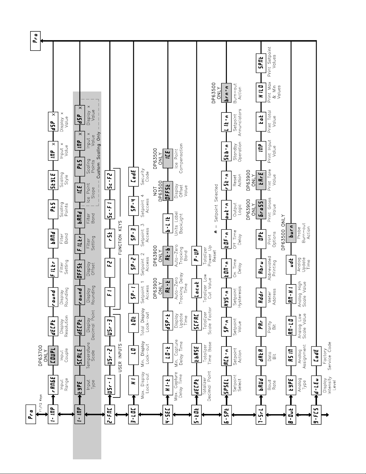
28
DP63X00 PROGRAMMING QUICK OVERVIEW
DP635
00 O
NLY
Page 29
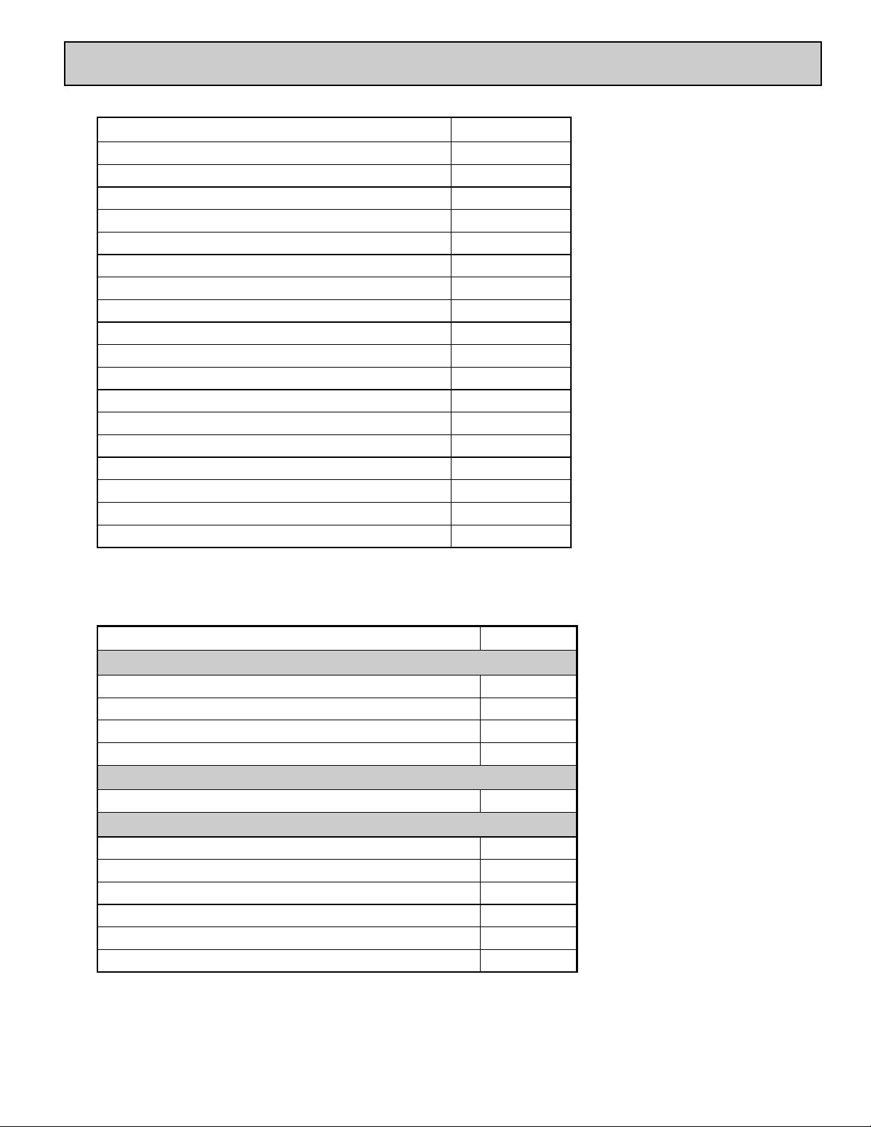
29
PART NUMBER INFORMATION
DESCRIPTION PART NUMBERS
Strain Gage Input, 85-250 VAC power
Process Input, 85-250 VAC power
AC Current and Volt Input, 85-250 VAC power
DC Current and Volt Input, 85-250 VAC power
Temperature Input, 85-250 VAC power
DP63900-S
DP63800-E
DP63700-AC
DP63600-DC
DP63500-T
Strain Gage Input, 11-36 VDC/24 VAC power
Process Input, 11-36 VDC/24 VAC power
DC Current and Volt Input, 11-36 VDC/24 VAC power
Temperature Input, 11-36 VDC/24 VAC power
DP63900-S-LV
DP63800-E-LV
DP63600-DC-LV
DP63500-T-LV
Strain Gage Input, 85-250 VAC power, green LED display
Process Input, 85-250 VAC power, green LED display
AC Current and Volt Input, 85-250 VAC power, green LED display
DC Current and Volt Input, 85-250 VAC power, green LED display
Temperature Input, 85-250 VAC power, green LED display
DP63900-S-GN
DP63800-E-GN
DP63700-AC-GN
DP63600-DC-GN
DP63500-T-GN
Strain Gage Input, 11-36 VDC/24 VAC power, green LED display
Process Input, 11-36 VDC/24 VAC power, green LED display
DC Current and Volt Input, 11-36 VDC/24 VAC power, green LED display
Temperature Input, 11-36 VDC/24 VAC power, green LED display
DP63900-S-GN-LV
DP63800-E-GN-LV
DP63600-DC-GN-LV
DP63500-T-GN-LV
ACCESSORIES
DESCRIPTION PART NUMBERS
Setpoint Alarms
Dual Setpoint relay output Card DP6-CDS10
Quad Setpoint relay output Card DP6-CDS20
Quad Setpoint sinking open collector output Card DP6-CDS30
Quad Setpoint sourcing open collector output Card DP6-CDS40
Analog Output
Extended MODBUS communications output card with dual RJ11 connectors
Extended RS485 serial communications output card with dual RJ11 connectors
Extended RS232 serial communications output card with 9-pin D connector
Communications
MODBUS communications output card with terminal block
RS485 serial communications output card with terminal block
RS232 serial communications output card with terminal block
Analog Output card
DP6-CDC4C
DP6-CDC1C
DP6-CDC2C
DP6-CDC40
DP6-CDC10
DP6-CDC20
DP6-CDL10
Page 30

30
Page 31

WARRANTY/DISCLAIMER
OMEGA ENGINEERING, INC. warrants this unit to be free of defects in materials and workmanship for a
period of 13 months from date of purchase. OMEGA’s WARRANTY adds an additional one (1) month grace
period to the normal one (1) year product warranty to cover handling and shipping time. This ensures
that OMEGA’s customers receive maximum coverage on each product.
If the unit malfunctions, it must be returned to the factory for evaluation. OMEGA’s Customer Service
Department will issue an Authorized Return (AR) number immediately upon phone or written request. Upon
examination by OMEGA, if the unit is found to be defective, it will be repaired or replaced at no charge.
OMEGA’s WARRANTY does not apply to defects resulting from any action of the purchaser, including but
not limited to mishandling, improper interfacing, operation outside of design limits, improper repair, or
unauthorized modification. This WARRANTY is VOID if the unit shows evidence of having been tampered
with or shows evidence of having been damaged as a result of excessive corrosion; or current, heat,
moisture or vibration; improper specification; misapplication; misuse or other operating conditions outside
of OMEGA’s control. Components in which wear is not warranted, include but are not limited to contact
points, fuses, and triacs.
OMEGA is pleased to offer suggestions on the use of its various products. However, OMEGA
neither assumes responsibility for any omissions or errors nor assumes liability for any
damages that result from the use of its products in accordance with information provided by
OMEGA, either verbal or written. OMEGA warrants only that the parts manufactured by the
company will be as specified and free of defects. OMEGA MAKES NO OTHER WARRANTIES OR
REPRESENTATIONS OF ANY KIND WHATSOEVER, EXPRESSED OR IMPLIED, EXCEPT THAT OF
TITLE, AND ALL IMPLIED WARRANTIES INCLUDING ANY WARRANTY OF MERCHANTABILITY
AND FITNESS FOR A PARTICULAR PURPOSE ARE HEREBY DISCLAIMED. LIMITATION OF
LIABILITY: The remedies of purchaser set forth herein are exclusive, and the total liability of
OMEGA with respect to this order, whether based on contract, warranty, negligence,
indemnification, strict liability or otherwise, shall not exceed the purchase price of the
component upon which liability is based. In no event shall OMEGA be liable for consequential,
incidental or special damages.
CONDITIONS: Equipment sold by OMEGA is not intended to be used, nor shall it be used: (1) as a “Basic
Component” under 10 CFR 21 (NRC), used in or with any nuclear installation or activity; or (2) in medical
applications or used on humans. Should any Product(s) be used in or with any nuclear installation or activity,
medical application, used on humans, or misused in any way, OMEGA assumes no responsibility as set forth
in our basic WARRANTY/DISCLAIMER language, and, additionally, purchaser will indemnify OMEGA and
hold OMEGA harmless from any liability or damage whatsoever arising out of the use of the Product(s) in
such a manner.
RETURN REQUESTS/INQUIRIES
Direct all warranty and repair requests/inquiries to the OMEGA Customer Service Department. BEFORE
RETURNING ANY PRODUCT(S) TO OMEGA, PURCHASER MUST OBTAIN AN AUTHORIZED RETURN (AR)
NUMBER FROM OMEGA’S CUSTOMER SERVICE DEPARTMENT (IN ORDER TO AVOID PROCESSING
DELAYS). The assigned AR number should then be marked on the outside of the return package and on any
correspondence.
The purchaser is responsible for shipping charges, freight, insurance and proper packaging to prevent
breakage in transit.
OMEGA’s policy is to make running changes, not model changes, whenever an improvement is possible. This affords our
customers the latest in technology and engineering.
OMEGA is a registered trademark of OMEGA ENGINEERING, INC.
© Copyright 2006 OMEGA ENGINEERING, INC. All rights reserved. This document may not be copied, photocopied,
reproduced, translated, or reduced to any electronic medium or machine-readable form, in whole or in part, without the
prior written consent of OMEGA ENGINEERING, INC.
FOR WARRANTY RETURNS, please have the
following information available BEFORE
contacting OMEGA:
1. Purchase Order number under which the product
was PURCHASED,
2. Model and serial number of the product under
warranty, and
3. Repair instructions and/or specific problems
relative to the product.
FOR NON-
WARRANTY REPAIRS, consult OMEGA
for current repair charges. Have the following
information available BEFORE contacting OMEGA:
1. Purchase Order number to cover the COST of the
repair,
2. Model and serial number of the product, and
3. Repair instructions and/or specific problems
relative to the product.
Page 32

Where Do I Find Everything I Need for
Process Measurement and Control?
OMEGA…Of Course!
Shop online at omega.com
TEMPERATURE
] Thermocouple, RTD & Thermistor Probes, Connectors, Panels & Assemblies
] Wire: Thermocouple, RTD & Thermistor
] Calibrators & Ice Point References
] Recorders, Controllers & Process Monitors
] Infrared Pyrometers
PRESSURE, STRAIN AND FORCE
] Transducers & Strain Gages
] Load Cells & Pressure Gages
] Displacement Transducers
] Instrumentation & Accessories
FLOW/LEVEL
] Rotameters, Gas Mass Flowmeters & Flow Computers
] Air Velocity Indicators
] Turbine/Paddlewheel Systems
] Totalizers & Batch Controllers
pH/CONDUCTIVITY
] pH Electrodes, Testers & Accessories
] Benchtop/Laboratory Meters
] Controllers, Calibrators, Simulators & Pumps
] Industrial pH & Conductivity Equipment
DATA ACQUISITION
] Data Acquisition & Engineering Software
] Communications-Based Acquisition Systems
] Plug-in Cards for Apple, IBM & Compatibles
] Datalogging Systems
] Recorders, Printers & Plotters
HEATERS
] Heating Cable
] Cartridge & Strip Heaters
] Immersion & Band Heaters
] Flexible Heaters
] Laboratory Heaters
ENVIRONMENTAL
MONITORING AND CONTROL
] Metering & Control Instrumentation
] Refractometers
] Pumps & Tubing
] Air, Soil & Water Monitors
] Industrial Water & Wastewater Treatment
] pH, Conductivity & Dissolved Oxygen Instruments
M4491/0706
 Loading...