

Page 1
INSTRUCTION
SHEET
Shop online at: omega.com e-mail: [email protected]
For latest product manuals: omegamanual.info
DP63100-S
PROCESS CONTROL EQUIPMENT
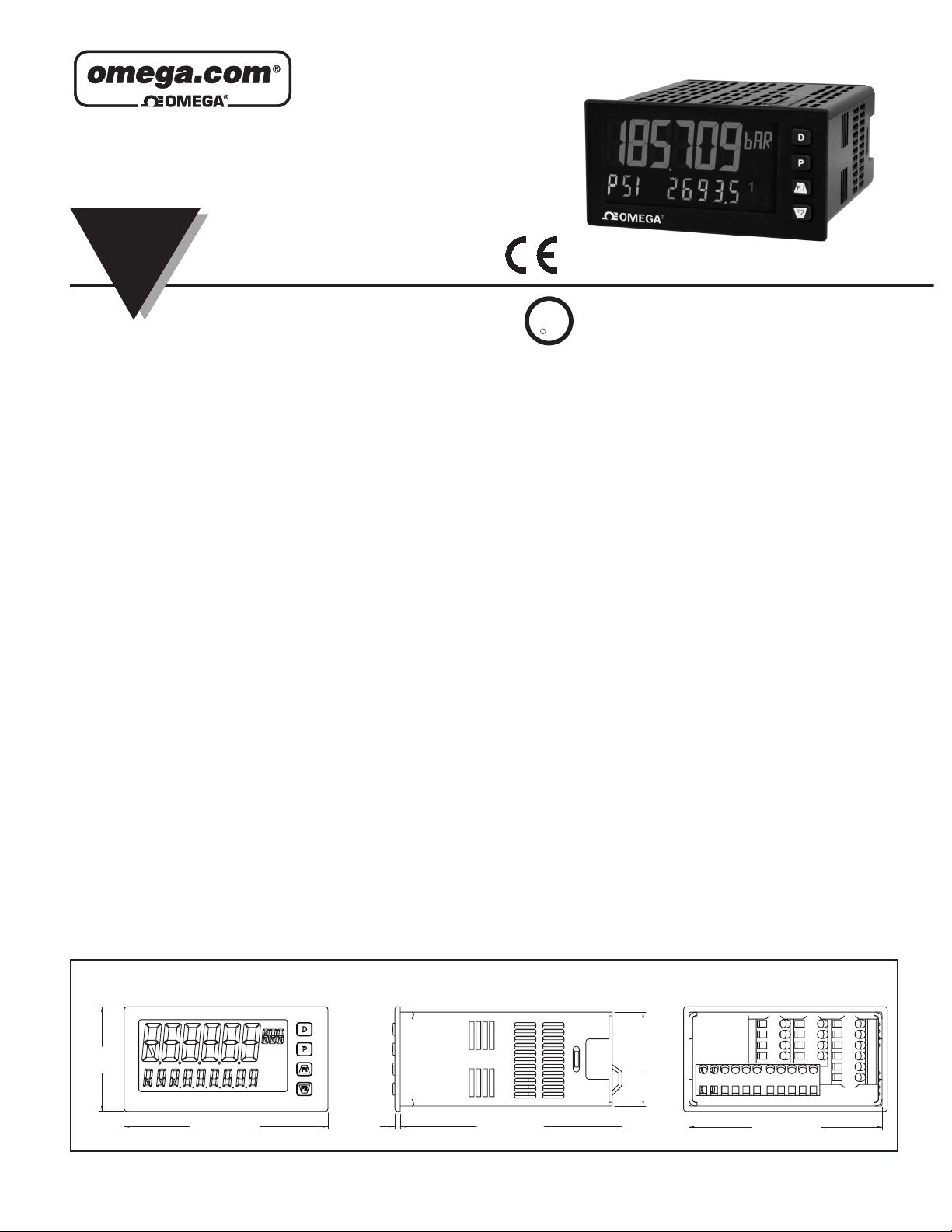
1/8 DIN Strain Gage Input Panel Meter
MQS5315-0713
U
R
C
US LISTED
L
3RSD
SPECIFICATIONS
POWER:
AC Power: 40 to 250 VAC, 50/60 Hz, 20 VA
DC Power: 21.6 to 250 VDC, 8 W
Isolation: 2300 Vrms for 1 min. to all inputs and outputs.
INPUT:
Connection Type: 4-wire bridge (differential); 2-wire (single-ended)
Common Mode Range (with respect to input common): 0 to +5 VDC
Rejection: 80 dB (DC to 120 Hz)
Input Ranges:
± 24 mVDC
± 240 mVDC
EXCITATION POWER: Jumper selectable
+5 VDC @ 65 mADC max., +/-2%
+10 VDC @ 125 mADC max., +/-2%
Temperature Coefficient (ratio metric): 20 ppm/ºC max.
USER INPUTS: Three programmable user inputs
Max. Continuous Input: 30 VDC
Isolation To Sensor Input Common: Not isolated.
CUSTOM LINEARIZATION:
Data Point Pairs: Selectable from 2 to 16
Display Range: -199,999 to 999,999
Decimal Point: 0 to 0.0000
ENVIRONMENTAL CONDITIONS:
Operating Temperature Range: 0 to 50 °C
Storage Temperature Range: -40 to 60 °C
Vibration to IEC 68-2-6: Operational 5-150 Hz, 2 g
Shock to IEC 68-2-27: Operational 25 g (10 g relay)
Operating and Storage Humidity: 0 to 85% max. RH non-condensing
Altitude: Up to 2000 meters
CERTIFICATIONS AND COMPLIANCES:
CE Approved
EN 61326-1 Immunity to Industrial Locations
Emission CISPR 11 Class A
IEC/EN 61010-1
RoHS Compliant
UL Listed: File #E70366
Type 4X Indoor Enclosure rating (Face only)
IP65 Enclosure rating (Face only)
IP20 Enclosure rating (Rear of unit)
CONNECTIONS: High compression cage-clamp terminal block
Wire Strip Length: 0.3" (7.5 mm)
Wire Gauge Capacity: One 14 AWG (2.55 mm) solid,
two 18 AWG (1.02 mm) or four 20 AWG (0.61 mm)
CONSTRUCTION: This unit is rated NEMA 4X/IP65 for indoor use only.
IP20 Touch safe. Installation Category II, Pollution Degree 2. One piece
bezel/ case. Flame resistant. Synthetic rubber keypad. Panel gasket and
mounting clip included.
WEIGHT: 8 oz. (226.8 g)
DIMENSIONS In inches (mm)
1.95
(49.53)
3.80 (96.52)
Note: Recommended minimum clearance (behind the panel) for mounting clip
installation is 2.1" (53.4) H x 5.5" (140) W.
1.75
1
2
3
4
0.10
(2.54)
4.14 (105)
(44.45)
3.60 (91.44)
LP0###A
LP0950A
Page 2
SAFETY SUMMARY
PANEL
LATCHING
SLOTS
BEZEL
PANEL
GASKET
PANEL
LATCH
LATCHING
TABS
PANEL
MOUNTING
SCREWS
All safety related regulations, local codes and instructions that appear in this
literature or on equipment must be observed to ensure personal safety and to
prevent damage to either the instrument or equipment connected to it. If
equipment is used in a manner not specified by the manufacturer, the protection
provided by the equipment may be impaired. Do not use this unit to directly
command motors, valves, or other actuators not equipped with safeguards. To do
so can be potentially harmful to persons or equipment in the event of a fault to
the unit.
CAUTION: Risk of Danger.
Read complete instructions prior to
installation and operation of the unit.
CAUTION:
Risk of electric shock.
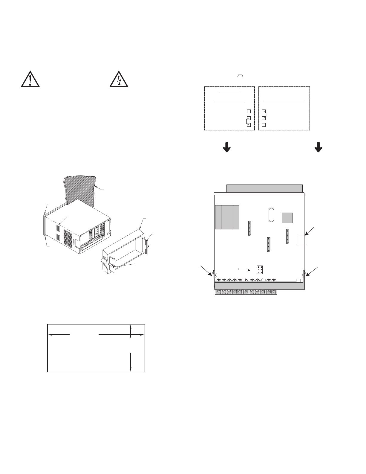
SETTING THE JUMPERS
Bridge Excitation
This jumper is used to select bridge excitation voltage level. Use the 5 V
excitation with high output (3 mV/V) bridges, so that the higher sensitivity 24
mV range can be used. Using the 5 V excitation also reduces bridge power
consumption compared to the 10 V excitation. A maximum of four 350 ohm load
cells can be driven by the internal bridge excitation voltage.
JUMPER SELECTIONS
The indicates factory setting.
BRIDGE
EXCITATION
INPUT RANGE
METER INSTALLATION
The DP63100-S meets NEMA 4X/IP65 requirements when properly
installed. The unit is intended to be mounted into an enclosed panel. Prepare the
panel cutout to the dimensions shown. Remove the panel latch from the unit.
Slide the panel gasket over the rear of the unit to the back of the bezel. The unit
should be installed fully assembled. Insert the unit into the panel cutout.
While holding the unit in place, push the panel latch over the rear of the unit
so that the tabs of the panel latch engage in the slots on the case. The panel latch
should be engaged in the farthest forward slot possible. To achieve a proper seal,
tighten the latch screws evenly until the unit is snug in the panel (Torque to
approximately 7 in-lbs [79N-cm]). Do not over-tighten the screws.
Finger
Tab
5V
10V
REAR TERMINALS
FRONT DISPLAY
Main Circuit Board
JUMPER
LOCATION
±24mV
±240mV
USB
Connector
Finger
Tab
Installation Environment
The unit should be installed in a location that does not exceed the operating
temperature and provides good air circulation. Placing the unit near devices that
generate excessive heat should be avoided.
PANEL CUT-OUT
+.03
3.62
-.00
+.8
(92 )
-.0
1.77
(45 )
+.02
-.00
+.5
-.0
REAR TERMINALS
2
Page 3
POWER WIRING
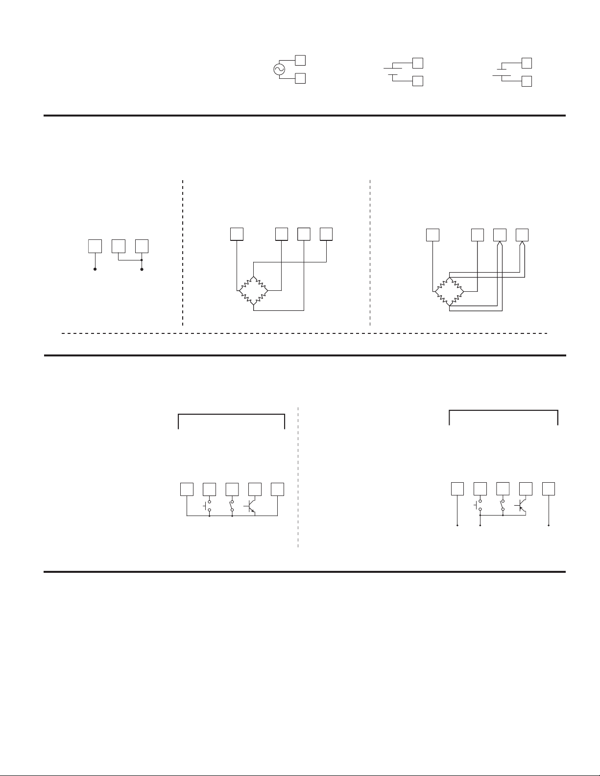
46
The power supplied to the meter shall employ a 15 Amp UL
approved circuit breaker for AC input and a 1 Amp, 250 V UL
approved fuse for DC input. It shall be easily accessible and
marked as a disconnecting device to the installed unit. This device
is not directly intended for connection to the mains without a
reliable means to reduce transient over-voltages to 1500 V.
AC Power
AC/DC
1
2
AC/DC
DC Power
+
-
1
2
AC/DC
AC/DC
OR
-
+
1
2
INPUT SIGNAL WIRING
IMPORTANT: Before connecting signal wires, the Input Range Jumper and Bridge Excitation Jumper should be verified for proper position.
AC/DC
AC/DC
2-Wire Single
Ended Input
- SIG
+ SIG
COMM
4-Wire Bridge Input
+SIG
-SIG
3 4
EXC
COMM
65
6-Wire Bridge Input
3 4 5
-EXC.
+EXC.
-SIG.
+SIG.
+ -
+SIG.
USER INPUT WIRING
If not using User Inputs, then skip this section. User Input terminal does not need to be wired in order to remain in inactive state.
Sinking Logic (USrACt LO)
When the USrACt parameter is
programmed to LO, the user inputs
of the meter are internally pulled up
to +3.3 V with 20 KW resistance.
The input is active when it is pulled
low (<1.1 V).
USER INPUTS
USER COMM
7
USER 3
USER 2
USER 1
118 9 10
Sourcing Logic (USrACt HI)
When the USrACt parameter is
programmed to HI, the user inputs of
the meter are internally pulled down
to 0 V with 20 KW resistance. The
input is active when a voltage greater
than 2.2 VDC is applied.
USER COMM
+SIG
-SIG
+SEN
+EXC.
-SIG.
-SEN
-EXC.
USER INPUTS
USER 1
USER COMM
87
COMM
53
USER 2
EXC
109
USER 3
USER COMM
11
SETPOINT (ALARMS) WIRING
SERIAL COMMUNICATION WIRING
ANALOG OUTPUT WIRING
See appropriate plug-in card bulletin for wiring details.
3
-
V
SUPPLY
+
(30V max.)
Page 4

OMEGAnet
omega.com
®
Online Service
Internet e-mail
Servicing North America:
U.S.A.: One Omega Drive, P.O. Box 4047
ISO 9001 Certified Stamford, CT 06907-0047
TEL: (203) 359-1660
FAX: (203) 359-7700
e-mail: [email protected]
Canada: 976 Bergar
For immediate technical or application assistance:
U.S.A. and Canada: Sales Service: 1-800-826-6342/1-800-TC-OMEGA
Customer Service: 1-800-622-2378/1-800-622-BEST
Engineering Service: 1-800-872-9436/1-800-USA-WHEN
®
®
Mexico: En Español: (001) 203-359-7803
It is the policy of OMEGA Engineering, Inc. to comply with all worldwide safety and EMC/EMI regulations that apply. OMEGA is constantly pursuing certification of its
products to the European New Approach Directives. OMEGA will add the CE mark to every appropriate device upon certification.
The information contained in this document is believed to be correct, but OMEGA accepts no liability for any errors it contains, and reserves the right to alter specifications without notice.
WARNING : These products are not designed for use in, and should not be used for, human applications.
Czech Republic: Frystatska 184, 733 01 Karviná, Czech Republic
Germany/Austria: Daimlerstrasse 26, D-75392 Deckenpfronn, Germany
TEL: +49 (0)7056 9398-0
FAX: +49 (0)7056 9398-29
Toll Free in Germany: 0800 639 7678
e-mail: [email protected]
United Kingdom: One Omega Drive, River Bend Technology Centre
ISO 9002 Certified Northbank, Irlam, Manchester
M44 5BD United Kingdom
TEL: +44 (0)161 777 6611
®
Servicing Europe:
WARRANTY/DISCLAIMER
OMEGA ENGINEERING, INC. warrants this unit to be free of defects in materials and workmanship for a period of 25 months from date of purchase.
OMEGA’s WARRANTY adds an additional one (1) month grace period to the normal two (2) year product warranty to cover handling and shipping time.
This ensures that OMEGA’s customers receive maximum coverage on each product.
If the unit malfunctions, it must be returned to the factory for evaluation. OMEGA’s Customer Service Department will issue an Authorized Return (AR)
number immediately upon phone or written request. Upon examination by OMEGA, if the unit is found to be defective, it will be repaired or replaced at no
charge. OMEGA’s WARRANTY does not apply to defects resulting from any action of the purchaser, including but not limited to mishandling, improper
interfacing, operation outside of design limits, improper repair, or unauthorized modification. This WARRANTY is VOID if the unit shows evidence of having
been tampered with or shows evidence of having been damaged as a result of excessive corrosion; or current, heat, moisture or vibration; improper
specification; misapplication; misuse or other operating conditions outside of OMEGA’s control. Components in which wear is not warranted, include but
are not limited to contact points, fuses, and triacs.
OMEGA is pleased to offer suggestions on the use of its various products. However, OMEGA neither assumes responsibility for any
omissions or errors nor assumes liability for any damages that result from the use of its products in accordance with information
provided by OMEGA, either verbal or written. OMEGA warrants only that the parts manufactured by the company will be as specified
and free of defects. OMEGA MAKES NO OTHER WARRANTIES OR REPRESENTATIONS OF ANY KIND WHATSOEVER, EXPRESSED OR
IMPLIED, EXCEPT THAT OF TITLE, AND ALL IMPLIED WARRANTIES INCLUDING ANY WARRANTY OF MERCHANTABILITY AND FITNESS
FOR A PARTICULAR PURPOSE ARE HEREBY DISCLAIMED. LIMITATION OF LIABILITY: The remedies of purchaser set forth herein are
exclusive, and the total liability of OMEGA with respect to this order, whether based on contract, warranty, negligence, indemnification,
strict liability or otherwise, shall not exceed the purchase price of the component upon which liability is based. In no event shall OMEGA
be liable for consequential, incidental or special damages.
CONDITIONS: Equipment sold by OMEGA is not intended to be used, nor shall it be used: (1) as a “Basic Component” under 10 CFR 21 (NRC), used in or
with any nuclear installation or activity; or (2) in medical applications or used on humans. Should any Product(s) be used in or with any nuclear installation
or activity, medical application, used on humans, or misused in any way, OMEGA assumes no responsibility as set forth in our basic WARRANTY/
DISCLAIMER language, and, additionally, purchaser will indemnify OMEGA and hold OMEGA harmless from any liability or damage whatsoever arising out
of the use of the Product(s) in such a manner.
Direct all warranty and repair requests/inquiries to the OMEGA Customer Service Department. BEFORE RETURNING ANY PRODUCT(S) TO OMEGA,
RETURN REQUESTS/INQUIRIES
PURCHASER MUST OBTAIN AN AUTHORIZED RETURN (AR) NUMBER FROM OMEGA’S CUSTOMER SERVICE DEPARTMENT (IN ORDER TO AVOID
PROCESSING DELAYS). The assigned AR number should then be marked on the outside of the return package and on any correspondence.
The purchaser is responsible for shipping charges, freight, insurance and proper packaging to prevent breakage in transit.
FOR WARRANTY RETURNS, please have the following information
available BEFORE contacting OMEGA:
1. Purchase Order number under which the product was PURCHASED,
2. Model and serial number of the product under warranty, and
3. Repair instructions and/or specific problems relative to the product.
OMEGA’s policy is to make running changes, not model changes, whenever an improvement is possible. This affords our customers the latest in technology and
engineering. OMEGA is a registered trademark of OMEGA ENGINEERING, INC.
© Copyright 2006 OMEGA ENGINEERING, INC. All rights reserved. This document may not be copied, photocopied, reproduced, translated, or reduced to any
electronic medium or machine-readable form, in whole or in part, without the prior written consent of OMEGA ENGINEERING, INC.
FOR NON-WARRANTY REPAIRS, consult OMEGA for current repair charges.
Have the following information available BEFORE contacting OMEGA:
1. Purchase Order number to cover the COST of the repair,
2. Model and serial number of the product, and
3. Repair instructions and/or specific problems relative to the product.
 Loading...