

Page 1
LP0690X
User’s Guide
DDPP6633000000AA-TT
DDPP6633000000BB-TT
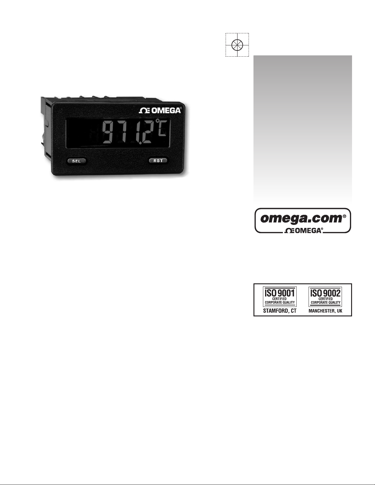
Digital PPanel MMeter
Shop online at
omega.com
e-mail: [email protected]
For latest product manuals:
omegamanual.info
Page 2

OMEGAnet®Online Service
omega.com
Internet e-mail
Servicing North America:
U.S.A.: One Omega Drive, P.O. Box 4047
ISO 9001 Certified Stamford, CT 06907-0047
TEL: (203) 359-1660 FAX: (203) 359-7700
e-mail: [email protected]
Canada: 976 Bergar
Laval (Quebec) H7L 5A1, Canada
TEL: (514) 856-6928 FAX: (514) 856-6886
e-mail: [email protected]
For immediate technical or application assistance:
U.S.A. and Canada: Sales Service: 1-800-826-6342/1-800-TC-OMEGA
®
Customer Service: 1-800-622-2378/1-800-622-BEST
®
Engineering Service: 1-800-872-9436/1-800-USA-WHEN
®
Mexico: En Español: (001) 203-359-7803 e-mail: [email protected]
FAX: (001) 203-359-7807 [email protected]
Servicing Europe:
Czech Republic: Frystatska 184, 733 01 Karviná, Czech Republic
TEL: +420 (0)59 6311899 FAX: +420 (0)59 6311114
Toll Free: 0800-1-66342
e-mail: [email protected]
Germany/Austria: Daimlerstrasse 26, D-75392 Deckenpfronn, Germany
TEL: +49 (0)7056 9398-0 FAX: +49 (0)7056 9398-29
Toll Free in Germany: 0800 639 7678
e-mail: [email protected]
United Kingdom: One Omega Drive, River Bend Technology Centre
ISO 9002 Certified Northbank, Irlam, Manchester
M44 5BD United Kingdom
TEL: +44 (0)161 777 6611 FAX: +44 (0)161 777 6622
Toll Free in United Kingdom: 0800-488-488
e-mail: [email protected]
It is the policy of OMEGA Engineering, Inc. to comply with all worldwide safety and EMC/EMI
regulations that apply. OMEGA is constantly pursuing certification of its products to the European New
Approach Directives. OMEGA will add the CE mark to every appropriate device upon certification.
The information contained in this document is believed to be correct, but OMEGA accepts no liability for any
errors it contains, and reserves the right to alter specifications without notice.
WARNING : These products are not designed for use in, and should not be used for, human applications.
Page 3
3
z COLD JUNCTION COMPENSATION (Enable/Disable)
z MINIMUM AND MAXIMUM DISPLAY CAPTURE
z LCD, REFLECTIVE OR GREEN/RED LED BACKLIGHTING
z 0.48" (12.2 mm) HIGH DIGITS
z OPTIONAL SETPOINT OUTPUT MODULES
z OPTIONAL SERIAL COMMUNICATION MODULES (RS232 or RS485)
z OPERATES FROM 9 TO 28 VDC POWER SOURCE
z FRONT PANEL OR SOFTWARE PROGRAMMABLE
z DISPLAY COLOR CHANGE CAPABILITY AT SETPOINT OUTPUT
z NEMA 4X/IP65 SEALED FRONT BEZEL
GENERAL DESCRIPTION
The DP63000 provides the user the ultimate in flexibility, from its complete
user programming to the optional setpoint control and communication
capability. This unit accepts a thermocouple input and provides a temperature
display in Celcius or Farenheit. The meter also features minimum and
maximum display capture, display offset, °F or °C indicator, and programmable
user input. The display can be toggled either manually or automatically between
the selected displays.
The DP63000 display has 0.48" (12.2 mm) high digits. The LCD is available
in two versions, reflective and red/green backlight. The backlight version is user
selectable for the desired color and also has variable display intensity.
The capability of the DP63000 can be easily expanded with the addition of
option modules. Setpoint capability is field installable with the addition of the
setpoint output modules. Serial communications capability for RS232 or RS485
is added with a serial option module.
The DP63000 can be powered from an optional Power Supply (Model
Number DP6-MLPS1), that attaches directly to the back of a DP63000. The
DP6-MLPS1 is powered from 85 to 250 VAC and provides up to 400 mA to
drive the unit and sensors.
SAFETY SUMMARY
All safety related regulations, local codes and instructions that appear in this
literature or on equipment must be observed to ensure personal safety and to
prevent damage to either the instrument or equipment connected to it. If
equipment is used in a manner not specified by the manufacturer, the protection
provided by the equipment may be impaired.
Do not use this meter to directly command motors, valves, or other actuators
not equipped with safeguards. To do so can be potentially harmful to persons or
equipment in the event of a fault to the meter.
CAUTION: Risk of Danger.
Read complete instructions prior to
installationand operation of the unit.
CAUTION: Risk of electric shock.
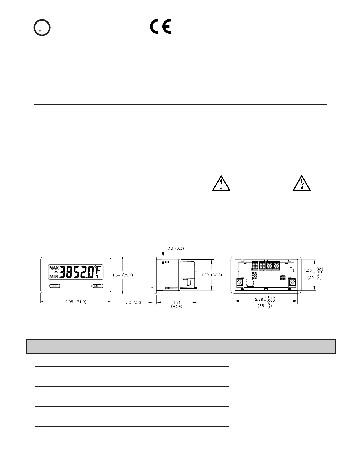
DIMENSIONS In inches (mm)
Note: Recommended minimum clearance (behind the panel) for mounting clip installation is 2.15" (54.6) H x 3.00" (76.2) W.
C
US LISTED
U
L
R
IND. CONT. EQ.
51EB
z THERMOCOUPLE INPUTS
Thermocouple types T, E, J, K, R, S, B, N, or mV
z PROGRAMMABLE TEMPERATURE OFFSET
z SELECTABLE °F or °C WITH 1 or 0.1 DEGREE RESOLUTION
z °F OR °C DISPLAY ANNUNCIATORS
z CONFORMS TO ITS-90 TEMPERATURE STANDARD
PART NUMBER INFORMATION
DP6-SNK0Dual Sinking Open Collector Output card
DP6-SOFT
DP6-485-CABLERS485 Programming Cable (DB9-RJ11)
DP63000B-T
PC Configuration Software for Windows 98, ME, 2000, XP
*
Thermocouple Input Meter with backlight display
DP6-232-CABLE
DP6-RLY0
DP6-MLPS1Micro-Line Power Supply, 85 to 250 VAC
Single Relay Output Card
RS232 Programming Cable (DB9-RJ11)
DP6-COM2RS232 Serial Communications Card
DP6-COM1RS485 Serial Communications Card
DP63000A-TThermocouple Input Meter with reflective display
PART NUMBERDESCRIPTION
Page 4
1. DISPLAY: 5 digit LCD 0.48" (12.2 mm) high digits
DP63000A-T: Reflective LCD with full viewing angle
DP63000B-T: Transmissive LCD with selectable red or green LED
backlight, viewing angle optimized. Display color change capability with
output state when using an output module.
2. POWER: Input voltage range is +9 to +28 VDC with short circuit and input
polarity protection. Must use a DP6-MLPS1 or an NEC Class 2 or SELV
rated power supply.
3. READOUT:
Resolution: 1 or 0.1 degrees
Scale: °F or °C
Offset Range: -999 to 9999 display units
4. THERMOCOUPLE INPUTS:
Isolation: TC+ and TC- terminals are not electrically isolated from the power
supply or optional comms cards.
Response Time: 500 msec.
Open Sensor Display:
OPEN
Overrange/Underrange Input: OLOL/ULUL
Overrange/Underrange Display : “.....”/“-.....”
Maximum Input Voltage: 30 VDC, TC+ to TC-
Maximum Input Voltage TC-: 3 VDC max. with respect to common
*After 20 min. warm-up. Accuracy is specified in two ways: Accuracy at
23°C and 15 to 75% RH environment; and Accuracy over a -35 to 75°C and 0
to 85% RH (non condensing) environment. Accuracy specified over the -35 to
75°C operating range includes meter tempco and cold junction tracking effects.
The specification includes the A/D conversion errors, linearization conformity,
and thermocouple cold junction compensation. T otal system accuracy is the sum
of meter and probe errors. Accuracy may be improved by field calibrating the
meter readout at the temperature of interest.
5. USER INPUT (USR): Programmable input. Connect terminal to common
(USR COMM) to activate function. Internal 10KΩ pull-up resistor to +9 to
28 VDC.
Threshold Levels: V
IL
= 1.0 V max; VIH= 2.4 V min; V
MAX
= 28 VDC
Response Time: 5 msec typ.; 50 msec debounce (activation and release)
6. CERTIFICATIONS AND COMPLIANCES:
SAFETY
UL Recognized Component, File #E313607, UL61010A-1, CSA 22.2 No. 61010-1
Recognized to U.S. and Canadian requirements under the Component
Recognition Program of Underwriters Laboratories, Inc.
UL Listed, File # E313547, UL508, CSA C22.2 No. 14-M95
LISTED by Und. Lab. Inc. to U.S. and Canadian safety standards
Type 4X Indoor Enclosure rating (Face only), UL50
IEC 61010-1, EN 61010-1: Safety requirements for electrical equipment
for measurement, control, and laboratory use, Part 1.
IP65 Enclosure rating (Face only), IEC 529
ELECTROMAGNETIC COMPATIBILITY
Emissions and Immunity to EN 61326: Electrical Equipment for
Measurement, Control and Laboratory use.
Note:
1. Criterion A: Normal operation within specified limits.
Refer to EMC Installation Guidelines for additional information.
7. MEMORY: Nonvolatile E
2
PROM memory retains all programming
parameters and max/min values when power is removed.
8. CONNECTIONS: Wire clamping screw terminals
Wire Strip Length: 0.3" (7.5 mm)
Wire Gage: 30-14 AWG copper wire
Torque: 5 inch-lbs (0.565 N-m) max.
9. ENVIRONMENTALCONDITIONS:
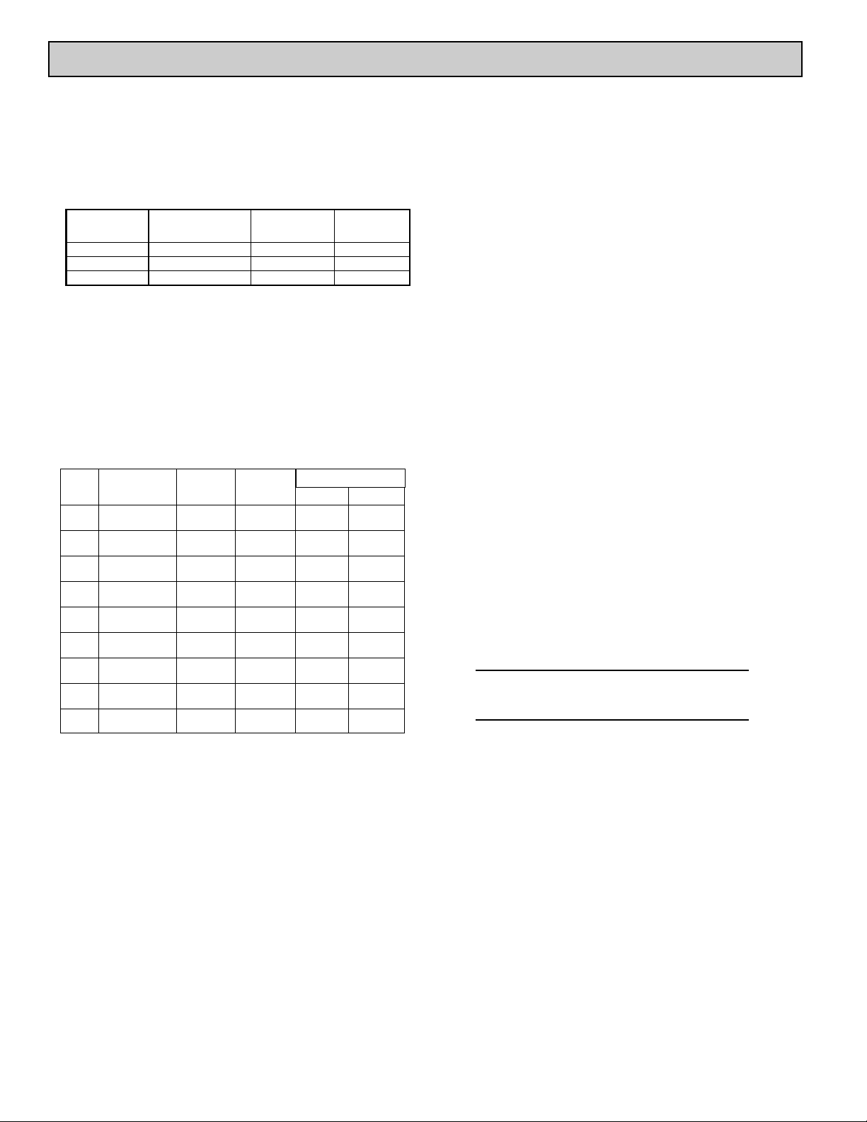
Operating Temperature Range for DP63000A-T: -35 to 75°C
Operating T emperatur e Range forDP63000B-T depends on display color
and intensity level as per below:
Storage Temperature: -35 to 85°C
Operating and Storage Humidity: 0 to 85% max. relative humidity (non-
condensing)
Altitude: Up to 2000 meters
10. CONSTRUCTION: This unit is rated for NEMA4X/IP65 requirements for
indoor use. Installation Category I, Pollution Degree 2. High impact plastic
case with clear viewing window. Panel gasket and mounting clip included.
11. WEIGHT: 3.2 oz (100 g)
4
GENERAL METER SPECIFICATIONS
MODEL
NO.
DISPLAYCOLOR
INPUT CURRENT
@ 9 VDC WITHOUT
DP6-RLY0
INPUT CURRENT
@ 9 VDC WITH
DP6-RLY0
DP63000A-T --- 10 mA 40 mA
DP63000B-T Red (max intensity) 85 mA 115 mA
DP63000B-T Green (max intensity) 95 mA 125 mA
TEMPERATURE
1 & 2 -35 to 75°C
3 -35 to 70°C
4 -35 to 60°C
5 -35 to 50°C
1 & 2 -35 to 75°C
3 -35 to 65°C
5
4
-35 to 35°C
-35 to 50°C
INTENSITY LEVEL
Class AEN 55011Emissions
Emissions:
30 A/m
3 V/rms
Criterion A
Criterion A
EN 61000-4-8
EN 61000-4-6RF conducted interference
1 kV L-L,
Criterion AEN 61000-4-5Surge
1 kV signal
2 kV power
Criterion AEN 61000-4-4Fast transients (burst)
2 kV L&N-E power
10 V/m
Criterion AEN 61000-4-3Electromagnetic RF fields
8 kV air discharge
4 kV contact discharge
Criterion AEN 61000-4-2Electrostatic discharge
Immunity to Industrial Locations:
Power frequency magnetic fields
Green Display
Red Display
ACCURACY
@ -35 to 75°C
±°C
0.08 mV
5.8
8.1
4.9
42.6<540°C
15.0>540
°C
15.0
no
standard
no
standard
0.02 mV-10.00 to 65.00mV
(+) brown
(-) blue
(+) yellow
(-) red
2.3
-200 to 1372°C
-328 to 2502°F
K
(+) orange
(-) blue
(+) orange
(-) red
2.8
-200 to 1300°C
-328 to 2372°F
N
(+) brown
(-) blue
(+) purple
(-) red
2.7
-200 to 871°C
-328 to 1600°F
E
no
standard
no
standard
9.1<540°C
4.5>540
°C
200 to 1820°C
392 to 3308°F
B
(+) white
(-) blue
no
standard
4.5
-50 to 1768°C
-58 to 3214°F
S
(+) white
(-) blue
no
standard
4.5
-50 to 1768°C
-58 to 3214°F
R
(+) yellow
(-) blue
(+) white
(-) red
1.9
-200 to 760°C
-328 to 1400°F
J
(+) white
(-) blue
(+) blue
(-) red
2.3
-200 to 400°C
-328 to 752°F
T
BS 1843ANSI
15.0
4.3
5.8
ACCURACY
@ 23°C
±°C
RANGETC TYPE
WIRE COLOR
Page 5
5
ADDING OPTION CARDS
The DP63000 meters can be fitted with optional output cards and/or serial
communications cards. The details for the plug-in cards can be reviewed in the
specification section below. The plug-in cards, that are sold separately, can be
installed initially or at a later date.
WARNING: Disconnect all power to the unit before
installing Plug-in card.
SINGLE RELAY CARD
Type: Single FORM-C relay
Isolation To Sensor & User Input Commons: 1400 Vrms for 1 min.
Working Voltage: 150 Vrms
Contact Rating: 1 amp @ 30 VDC resistive; 0.3 amp @ 125 VAC resistive
Life Expectancy: 100,000 minimum operations
Response Time:
Turn On Time: 4 msec max.
Turn Off Time: 4 msec max.
DUAL SINKING OUTPUT CARD
Type: Non-isolated switched DC, N Channel open drain MOSFET
Current Rating: 100 mA max.
V
DS ON
: 0.7 V @ 100 mA
V
DS MAX
: 30 VDC
Offstate Leakage Current: 0.5 mA max.
RS485 SERIAL COMMUNICATIONS CARD
Type: RS485 multi-point balanced interface (non-isolated)
Note: Non-grounded (isolated) thermocouple probes must be used when
multiple units are connected in an RS485 network, or measurement
errors will occur.
Baud Rate: 300 to 38.4k
Data Format: 7/8 bits; odd, even, or no parity
Bus Address: 0 to 99; max 32 meters per line
Transmit Delay: Selectable (refer to DP6-COM bulletin)
RS232 SERIAL COMMUNICATIONS CARD
Type: RS232 half duplex (non-isolated)
Baud Rate: 300 to 38.4k
Data Format: 7/8 bits; odd, even, or no parity
OPTIONAL PLUG-IN CARDS
1.0 INSTALLING THE METER
INSTALLATION
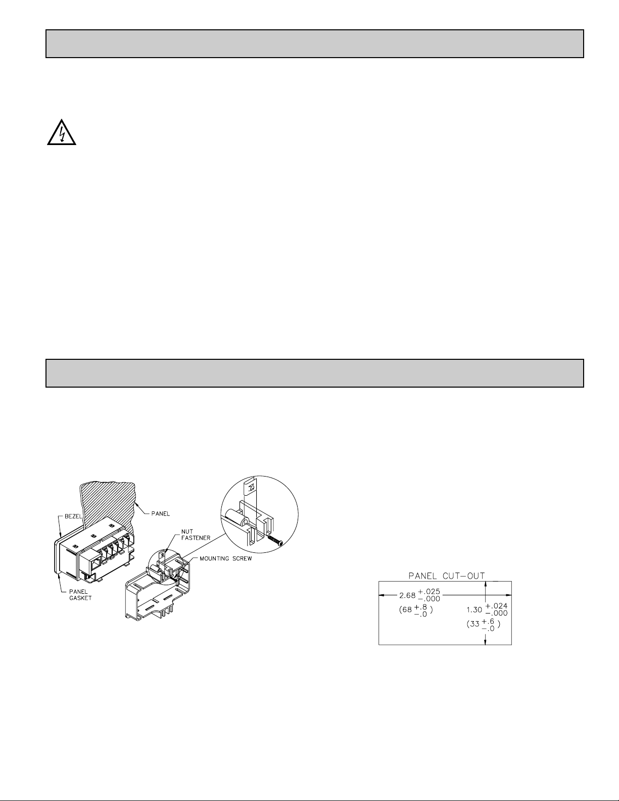
The meter meets NEMA 4X/IP65 requirements when properly installed. The
unit is intended to be mounted into an enclosed panel. Prepare the panel cutout
to the dimensions shown. Remove the panel latch from the unit. Slide the panel
gasket over the rear of the unit to the back of the bezel. The unit should be
installed fully assembled. Insert the unit into the panel cutout.
While holding the unit in place, push the panel latch over the rear of the unit
so that the tabs of the panel latch engage in the slots on the case. The panel latch
should be engaged in the farthest forward slot possible. T o achieve a proper seal,
tighten the latch screws evenly until the unit is snug in the panel (Torque to
approx. 28 to 36 in-oz [0.202 to 0.26 N-m]). Do not over-tighten the screws.
INSTALLATION ENVIRONMENT
The unit should be installed in a location that does not exceed the operating
temperature and provides good air circulation. Placing the unit near devices that
generate excessive heat should be avoided.
The bezel should only be cleaned with a soft cloth and neutral soap product.
Do NOT use solvents. Continuous exposure to direct sunlight may accelerate the
aging process of the bezel.
Do not use tools of any kind (screwdrivers, pens, pencils, etc.) to operate the
keypad of the unit.
Page 6
WIRING OVERVIEW
Electrical connections are made via screw-clamp terminals located on the
back of the meter. All conductors should conform to the meter ’s voltage and
current ratings. All cabling should conform to appropriate standards of good
installation, local codes and regulations. It is recommended that the power
supplied to the meter (DC or AC) be protected by a fuse or circuit breaker.
Strip the wire, leaving approximately 0.3" (7.5 mm) bare lead exposed
(stranded wires should be tinned with solder.) Insert the lead under the correct
screw-clamp terminal and tighten until the wire is secure. (Pull wire to verify
tightness.) Each terminal can accept up to one #14 AWG (2.55 mm) wire, two
#18 AWG (1.02 mm), or four #20 AWG (0.61 mm).
EMC INSTALLATION GUIDELINES
Although this meter is designed with a high degree of immunity to ElectroMagnetic Interference (EMI), proper installation and wiring methods must be
followed to ensure compatibility in each application. The type of the electrical
noise, source or coupling method into the meter may be different for various
installations. The meter becomes more immune to EMI with fewer I/O
connections. Cable length, routing, and shield termination are very important
and can mean the difference between a successful or troublesome installation.
Listed below are some EMC guidelines for successful installation in an
industrial environment.
1. The meter should be mounted in a metal enclosure, which is properly
connected to protective earth.
2. Use shielded (screened) cables for all Signal and Control inputs. The shield
(screen) pigtail connection should be made as short as possible. The
connection point for the shield depends somewhat upon the application.
Listed below are the recommended methods of connecting the shield, in order
of their effectiveness.
a. Connect the shield only at the panel where the unit is mounted to earth
ground (protective earth).
b. Connect the shield to earth ground at both ends of the cable, usually when
the noise source frequency is above 1 MHz.
c. Connect the shield to common of the meter and leave the other end of the
shield unconnected and insulated from earth ground.
3. Never run Signal or Control cables in the same conduit or raceway with AC
power lines, conductors feeding motors, solenoids, SCR controls, and
heaters, etc. The cables should be ran in metal conduit that is properly
grounded. This is especially useful in applications where cable runs are long
and portable two-way radios are used in close proximity or if the installation
is near a commercial radio transmitter.
4. Signal or Control cables within an enclosure should be routed as far as possible
from contactors, control relays, transformers, and other noisy components.
5. In extremely high EMI environments, the use of external EMI suppression
devices, such as ferrite suppression cores, is effective. Install them on Signal
and Control cables as close to the unit as possible. Loop the cable through the
core several times or use multiple cores on each cable for additional protection.
Install line filters on the power input cable to the unit to suppress power line
interference. Install them near the power entry point of the enclosure. The
following EMI suppression devices (or equivalent) are recommended:
Ferrite Suppression Cores for signal and control cables:
Fair-Rite # 0443167251
TDK # ZCAT3035-1330A
Steward # 28B2029-0A0
Line Filters for input power cables:
Schaffner # FN610-1/07
Schaffner # FN670-1.8/07
Corcom # 1 VR3
Note: Reference manufacturer’s instructions when installing a line filter.
6. Long cable runs are more susceptible to EMI pickup than short cable runs.
Therefore, keep cable runs as short as possible.
7. Switching of inductive loads produces high EMI. Use of snubbers across
inductive loads suppresses EMI.
3.0 W
IRING THE M
ETER
6
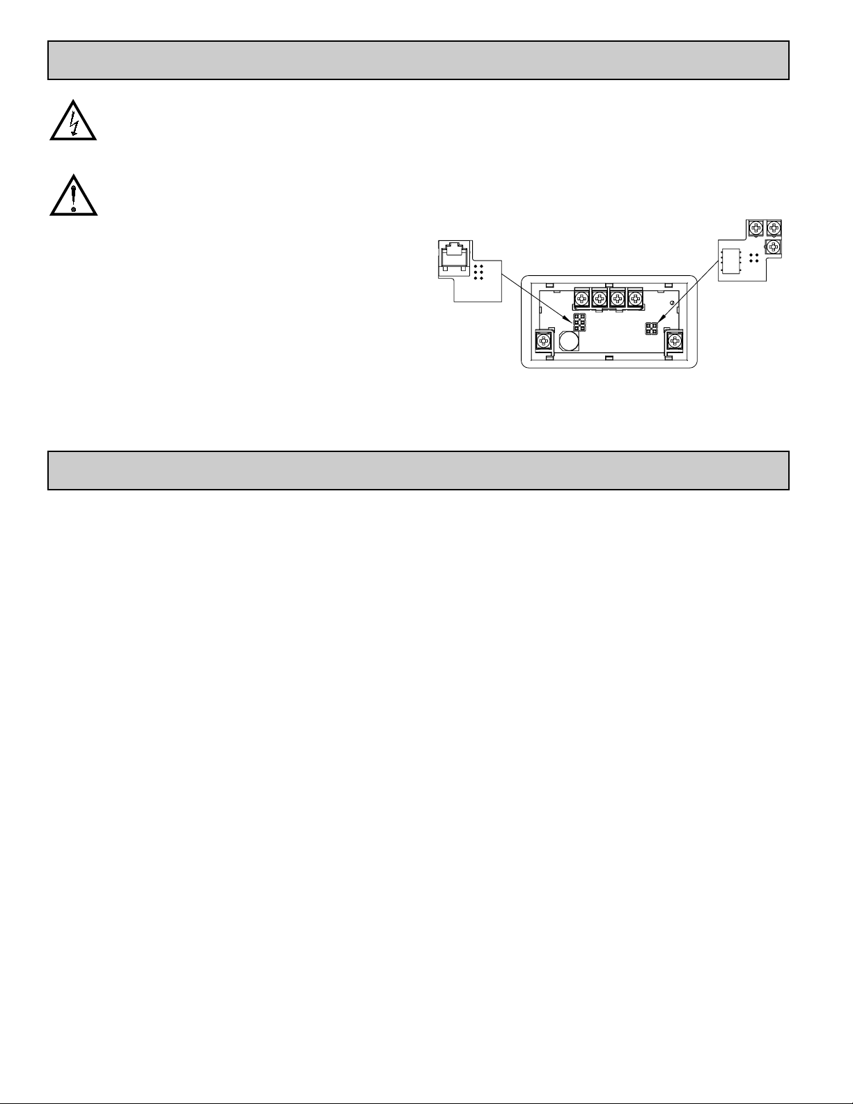
2.0 INSTALLING PLUG-IN CARDS
WARNING: Exposed line voltage exists on the circuit boards.
Remove all power to the meter and load circuits before
accessing inside of the meter.
CAUTION: The Plug-in cards and main circuit board contain static
sensitive components. Before handling the cards, discharge
static charges from your body by touching a grounded bare
metal object. Ideally, handle the cards at a static controlled
clean workstation. Also, only handle the cards by the edges.
Dirt, oil or other contaminants that may contact the cards can
adversely affect circuit operation.
REMOVING THE REAR COVER
To remove the rear cover, locate the cover locking tab below the 2nd and 3rd
input terminals. T o release the tab, insert a small, flat blade screwdriver between
the tab and the plastic wall below the terminals. Inserting the screwdriver will
provide enough pressure to release the tab locks. To replace the cover, align the
cover with the input terminals and press down until the cover snaps into place.
The Plug-in cards are separately purchased option cards that perform specific
functions. The cards plug into the main circuit board of the meter.
Comms Card
Setpoint Card
Page 7
7
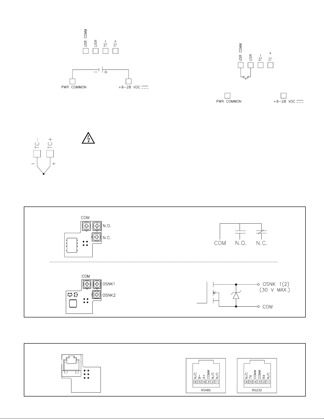
3.1 POWER WIRING
DC Power
+9 to +28 VDC: +VDC
Power Common: -VDC
3.2 USER INPUT WIRING
Sinking Logic
USR COMM
USR
The user input of the meter is
internally pulled up to +9 to +28 V
with 10 K resistance. The input is
active when it is pulled low (<0 .7 V).
Connect external switching device between the
User Input terminal and User Input Common.
}
3.3 INPUT WIRING
3.4 SETPOINT (OUTPUT) WIRING
3.5 SERIAL COMMUNICATION WIRING
SINGLE SETPOINT RELAY PLUG-IN CARD
SERIAL COMMUNICATIONS PLUG-IN CARD
RJ11 CONNECTOR PIN OUTS
ELECTRICAL CONNECTIONS
DUAL SETPOINT N-FET OPEN DRAIN PLUG-IN CARD
ELECTRICAL CONNECTIONS
Thermocouple
CAUTION: Power input common and sensor input common are NOT isolated
from user input common. In order to preserve the safety of the meter
application, the power ionput common and the sensor input common must
be suitably isolated from hazardous live earth referenced voltages; or
input common must be at protective earth ground potential. If not, hazardous
live voltage may be present at the User Inputs and User Input Common
terminals. Appropriate considerations must then be given to the potential of
the user input common with respect to earth common; and the common of
the isolated plug-in cards with respect to input common.
Page 8
8
4.0 REVIEWING THE FRONT BUTTONS AND DISPLAY
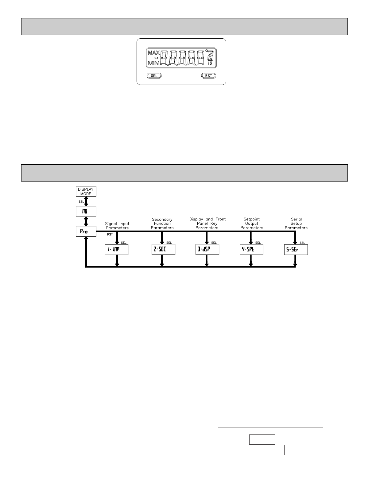
PROGRAMMING MODE ENTRY (SEL BUTTON)
It is recommended that all programming changes be made off line, or before
installation. The meter normally operates in the Display Mode. No parameters
can be programmed in this mode. The Programming Mode is entered by
pressing and holding the
SEL button. If it is not accessible then it is locked by
either a security code, or a hardware lock.
MODULE ENTRY (SEL & RST BUTTONS)
The Programming Menu is organized into separate modules. These modules
group together parameters that are related in function. The display will alternate
between
Pro and the present module. The RST button is used to select the desired
module. The displayed module is entered by pressing the
SEL button.
MODULE MENU (SEL BUTTON)
Each module has a separate module menu (which is shown at the start of each
module discussion). The
SEL button is pressed to advance to a particular
parameter to be changed, without changing the programming of preceding
parameters. After completing a module, the display will return to
Pro NO.
Programming may continue by accessing additional modules.
SELECTION / VALUE ENTRY
For each parameter, the display alternates between the present parameter and
the selections/value for that parameter. The
RST button is used to move through
the selections/values for that parameter. Pressing the
SEL button, stores and
activates the displayed selection/value. This also advances the meter to the next
parameter.
For numeric values, press the
RST button to access the value. The right hand
most digit will begin to flash. Pressing the
RST button again increments the
digit by one or the user can hold the
RST button and the digit will automatically
scroll. The
SEL button will advance to the next digit. Pressing and holding the
SEL button will enter the value and move to the next parameter.
PROGRAMMING MODE EXIT (SEL BUTTON)
The Programming Mode is exited by pressing the SEL button with Pro NO
displayed. This will commit any stored parameter changes to memory and
return the meter to the Display Mode. (If power loss occurs before returning to
the Display Mode, verify recent parameter changes.)
PROGRAMMING TIPS
It is recommended to start with Module 1 and proceed through each module
in sequence. When programming is complete, it is recommended to record the
parameter programming and lock out parameter programming with the user
input or programming security code.
FACTORY SETTINGS
Factory Settings may be completely restored in Module 2. This is useful
when encountering programming problems.
Pressing both the
SEL and the RST button on power-up will also load the
factory settings and display
rESEt. This allows operation in the event of a
memory failure or corrupted data.
ALTERNATING SELECTION DISPLAY
In the explanation of the modules, the following dual display with arrows will
appear. This is used to illustrate the display alternating between the parameter
on top and the parameter’s Factory Setting on the bottom. In most cases,
selections and values for the parameter will be listed on the right.
5.0 PROGRAMMING THE METER
OVERVIEW
PROGRAMMING MENU
Indicates Program Mode Alternating Display
Factory Settings are shown.
Parameter
Selection/Value
BUTTON DISPLAY MODE OPERATION ENTERING PROGRAM MODE PROGRAMMING MODE OPERATION
SEL Index display through enabled values Press and hold for 2 seconds to activate Store selected parameter and index to next parameter
RST Resets values (MIN / MAX) or outputs
Advances through the program menu
Increments selected parameter value or selection
OPERATING MODE DISPLAY DESIGNATORS
MAX - Maximum display capture value
MIN - Minimum display capture value
“1” - To the right of the display indicates setpoint 1 output activated.
“2” - To the right of the display indicates setpoint 2 output activated.
Pressing the SEL button toggles the meter through the selected displays. If display scroll is enabled, the display will toggle automatically every four seconds between
the enabled display values.
ª
«
N0
USrIN
Page 9
9
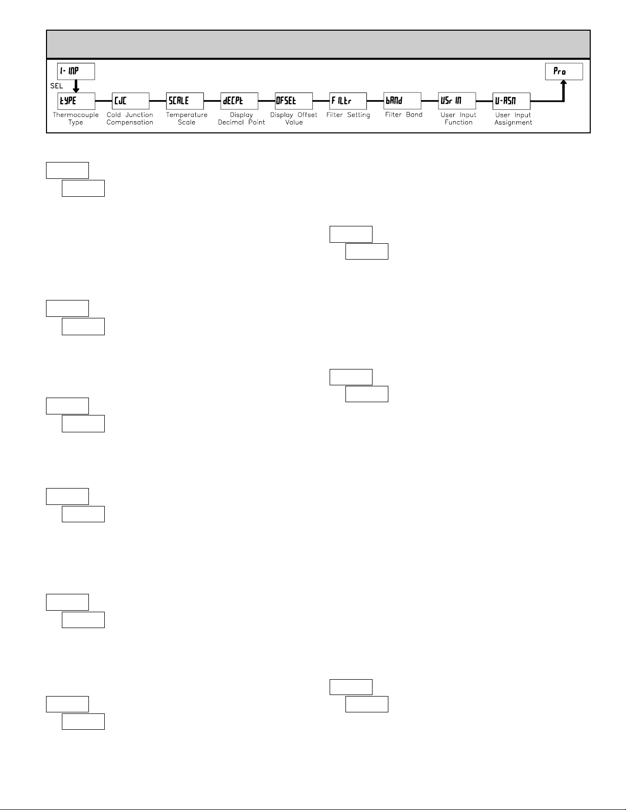
5.1 MODULE 1 - SIGNAL INPUT
PARAMETERS (
1-INP)
PARAMETER MENU
ª
«
tc-J
tYPE
THERMOCOUPLE TYPE
ª
«
0
dECPt
0.00
DISPLAY DECIMAL POINT
Select the decimal point location for the desired display resolution. This
selection applies for the Input, MAX and MIN displays. This parameter does
not appear if
tYPE = VOLt or for types R, S or B thermocouples which have a
fixed 1 degree resolution.
ª
«
1
FILtr
FILTER SETTING
If the displayed temperature is difficult to read due to small process
variations or noise, increased levels of filtering will help to stabilize the display.
Software filtering effectively combines a fraction of the current input reading
with a fraction of the previous displayed reading to generate the new display.
0,1 2 3
ª
«
10
bANd
FILTER BAND
The filter will adapt to variations in the input signal. When the variation
exceeds the input filter band value, the filter disengages. When the variation
becomes less than the band value, the filter engages again. This allows for a
stable readout, but permits the display to settle rapidly after a large process
change. The value of the band is in display units, independent of the Display
Decimal Point position. A band setting of ‘0’ keeps the filter permanently
engaged at the filter level selected above.
00 to 199 display units
Select the thermocouple type used for the application. The appropriate curve
will be automatically loaded for the selected type.
Selecting
VOLt displays the millivolt input signal with 10 μV resolution.
ª
«
°F
SCALE
TEMPERATURE SCALE
Select the temperature scale. This selection applies for the Input, MAX and
MIN displays. This parameter does not appear if
tYPE = VOLt.
°C°F
R
tc-r
SELECTION TC TYPETC TYPESELECTION
VOLt
tc-n
N
K
tc-b
tc-S
tc-K
B
S
J
tc-j
E
tc-E
T
tc-t
ª
«
0
OFSEt
DISPLAY OFFSET VALUE
The temperature display can be corrected with an offset value. This can be
used to compensate for probe errors, errors due to variances in probe placement
or adjusting the readout to a reference thermometer.
-999 to 9999
This parameter enables or disables internal cold junction compensation. For
most applications, cold junction compensation should be enabled (
yES). This
parameter does not appear if
tYPE = VOLt.
COLD JUNCTION COMPENSATION
NOyES
ª
«
yES
CJC
USER INPUT FUNCTION
ª
«
NO
USrIN
Setpoint 1 and 2 Reset
Setpoint 1 Reset
Setpoint 2 Reset
Print and Reset
Reset both setpoint 1 and 2 outputs.
Resets setpoint 1 output.
Resets setpoint 2 output.
Same as Print Request followed by a
momentary reset of the assigned value(s).
rSt12
rSt-1
rSt-2
P-r5t
Print Request
Serial transmit of the active parameters
selected in the Print Options menu
(Module 5).
Print
Select the value(s) to which the User Input Function is assigned. The User
Input Assignment only applies if a selection of reset, display hold, or print and
reset is selected in the User Input Function menu.
USER INPUT ASSIGNMENT
ª
«
dSP
U-ASN
Filter values represent no filtering (0), up to heavy filtering (3). Avalue of 1
for the filter uses 1/4 of the new input and 3/4 of the previous display to
generate the new display. A filter value of 2 uses 1/8 new and 7/8 previous. A
filter value of 3 uses 1/16 new and 15/16 previous.
dSP
HI-LO
LO
HI
MODE
Reset (Edge triggered)
Program Mode Lock-out
No Function
DESCRIPTIONDISPLAY
Display Select
(Edge Triggered)
Advance once for each activation.
d-SEL
Backlight Color
(Edge Triggered)
Change backlight color with each
activation (backlight version only).
COLOr
Display Intensity Level
(Edge Triggered)
Increase intensity one level for each
activation (backlight version only).
d-LEV
Display Hold
Holds the assigned display, but all other
meter functions continue as long as
activated (maintained action).
Resets the assigned value(s) to the
current input value.
rESEt
d-HLd
See Programming Mode Access chart
(Module 3).
P-Loc
User Input disabled.
NO
Page 10
10
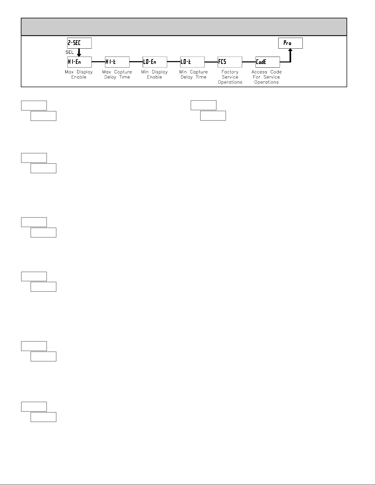
5.2 MODULE 2 - SECONDARY FUNCTION PARAMETERS (2-SEC)
PARAMETER MENU
MIN DISPLAY ENABLE
YESNO
ª
«
2.0
HI-t
ª
«
NO
LO-En
ª
«
NO
FCS
MAX CAPTURE DELAY TIME
When the Input Display is above the present MAX value for the entered
delay time, the meter will capture that display value as the new MAX reading.
A delay time helps to avoid false captures of sudden short spikes.
ª
«
2.0
LO-t
MIN CAPTURE DELAY TIME
When the Input Display is below the present MIN value for the entered delay
time, the meter will capture that display value as the new MIN reading. Adelay
time helps to avoid false captures of sudden short spikes.
0.0 to 999.9 sec.
ª
«
NO
HI-En
MAX DISPLAY ENABLE
0.0 to 999.9 sec.
Select YES to perform either of the Factory Service Operations shown below.
FACTORY SERVICE OPERATIONS
yESNO
YESNO
Enables the Maximum Display Capture capability.
Enables the Minimum Display Capture capability.
The unit uses stored voltage calibration and cold
junction temperature values to provide accurate
temperature and voltage measurements. Over time, the
electrical characteristics of the components inside the
meter could slowly change. The result is that the stored
calibration values may no longer accurately define the input circuit. For most
applications, recalibration every 1 to 2 years should be sufficient.
Calibration of the unit involves a voltage calibration and a cold junction
calibration. It is recommended that both calibrations be performed. The voltage
calibration MUST precede the cold junction calibration. Allow 30 minute warm
up before performing any calibration related procedure. The following
procedures should be performed at an ambient temperature of 15 to 35 °C (59
to 95 °F).
Calibration should only be performed by individuals experienced in
calibrating electronic equipment.
CAUTION: The accuracy of the calibration equipment will directly affect the
accuracy of the unit.
Input Voltage Calibration
1. Connect a precision DC voltage source with an accuracy of 0.01% or better
to the TC+ (positive) and the TC- (negative) terminals of the unit. Set the
output of the voltage source to zero.
2. With the display at
CodE 48, press and hold the SEL button for 2 seconds. Unit
will display
CAL NO.
3. Press the
RST button to select INP.
4. Press the
SEL button. Display reads 0.0u.
5. With the voltage source set to zero, press
SEL. Display reads CALC for about
eight seconds.
6. When display reads
60.0u, apply 60.000 mV input signal. Press SEL. Display
reads
CALC for about eight seconds.
7. When display reads
CAL NO, press SEL twice to exit Module 2 and return to
the normal display mode.
8. Proceed to Cold Junction Calibration.
Cold Junction Calibration
1. Install all option cards needed for your application and the rear cover,
or invalid results will occur.
2. The ambient temperature must be within 20°C to 30°C.
3. Connect a thermocouple (types T , E, J, K, or N only) with an accuracy of 1°C
or better to the meter.
4. Enter programming mode and verify the following settings in Module 1:
tYPE = thermocouple type connected to the unit
CJC = YES; SCALE = °C; dECPt = 0.0; OFSEt = 0
5. Place the thermocouple in close thermal contact to a reference thermometer
probe. (Use a reference thermometer with an accuracy of 0.25°C or better.)
The two probes should be shielded from air movement and allowed sufficient
time to equalize in temperature. (A calibration bath of known temperature
could be used in place of the thermometer.)
6. Compare the unit display with the reference temperature indicator (or
calibration bath). If a difference of more than ±1.0 °C exists, note the
difference (CJ error) and continue with cold junction calibration.
CJ Error = Reference Temperature - Unit Display.
7. Enter programming mode. Step through Module 2 to the Service Access
Code parameter and select
CodE 48. Press and hold the SEL button until the
unit displays
CAL NO. Press the RST button to select CJC.
8. Press
SEL. Display reads CJC followed by the current cold junction value.
Calculate a new cold junction value as follows:
New cold junction = Current cold junction + CJ Error (noted above)
9. Press RST and set the display to the new cold junction value. Press and hold
SEL. Display reads CALC for about four seconds and then returns to CAL NO.
10. Press
SEL twice to exit calibration and return to the normal display mode.
Verify the input reading is correct. If not, repeat steps 6 through 10.
CALIBRATION
ª
«
48
CodE
RESTORE FACTORY DEFAULT SETTINGS
Entering Code 66 will overwrite all user settings with
the factory settings. The meter will display
rESEt and then
return to
CodE 00. Press SEL button to exit the module.
Pressing both the SEL and the RST button on power-up
will also load the factory settings and display
rESEt. This allows operation in
the event of a memory failure or corruted data.
ª
«
66
CodE
Page 11
11
The Security Code determines the programming mode and the accessibility
of programming parameters. This code can be used along with the Program
Mode Lock-out (
P-Loc) in the User Input Function parameter (Module 1).
Two programming modes are available. Full Programming mode allows all
parameters to be viewed and modified. Quick Programming mode permits only
the Setpoint values to be modified, but allows direct access to these values
without having to enter Full Programming mode.
Programming a Security Code other than 0, requires this code to be entered
at the
CodE prompt in order to access Full Programming mode. Depending on the
code value, Quick Programming may be accessible before the
CodE prompt
appears (see chart).
PROGRAMMING SECURITY CODE
000 to 999
USER INPUT
FUNCTION
USER INPUT
STATE
SECURITY
CODE
MODE WHEN “SEL”
BUTTON IS PRESSED
FULL PROGRAMMING
MODE ACCESS
0 Full Programming Immediate Access
not P-Loc
______
1-99 Quick Programming
100-999
CodE prompt
With correct code entry
at
CodE prompt *
0 Programming Lock No Access
Active
1-99 Quick Programming No Access
P-Loc
100-999
CodE prompt
With correct code entry
at
CodE prompt *
Not Active 0-999 Full Programming Immediate Access
* Entering Code 222 allows access regardless of security code.
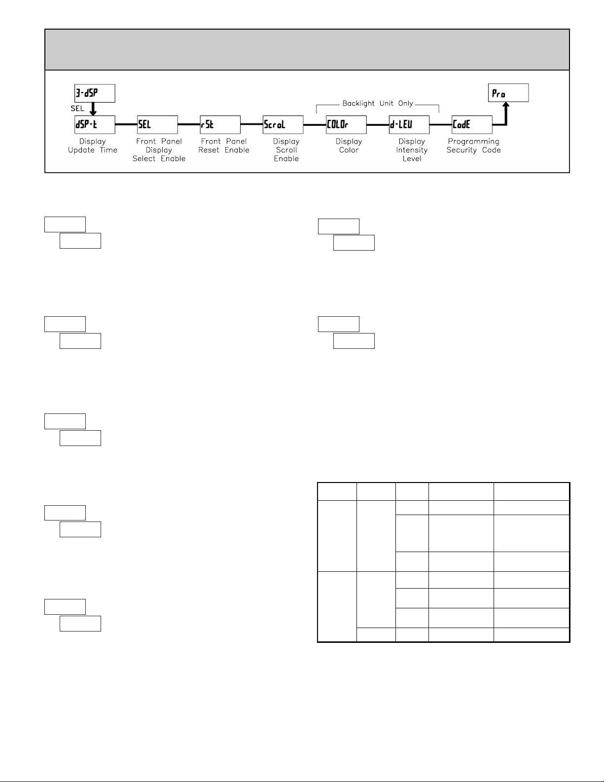
5.3 MODULE 3 - DISPLAY AND F
RONT PANEL B
UTTON
PARAMETERS (3-dSP)
PARAMETER MENU
The yES selection allows the SEL button to toggle through the enabled
displays.
FRONT PANEL DISPLAY SELECT ENABLE (SEL)
This selection allows the RST button to reset the selected value(s).
FRONT PANEL RESET ENABLE (RST)
The yES selection allows the display to automatically scroll through the
enabled displays. The scroll rate is every 4 seconds.
DISPLAY SCROLL ENABLE
NOyES
dSPNO
HI
LO
HI-LO
NOyES
Enter the desired display color, red or green. This parameter is active for
backlight units only.
DISPLAY COLOR (BACKLIGHT UNIT ONLY)
6rnrEd
Enter the desired Display Intensity Level (1-5). The display will actively dim
or brighten as levels are changed. This parameter is active for backlight units only .
DISPLAY INTENSITY LEVEL (BACKLIGHT UNIT ONLY)
1 to 5
ª
«
1
dSP-t
ª
«
yES
SEL
ª
«
dSP
rSt
ª
«
NO
ScroL
ª
«
rEd
COLOr
ª
«
5
d-LEV
ª
«
000
CodE
DISPLAY UPDATE TIME
This parameter sets the display update time in seconds.
10.5 2
seconds
After Quick
Programming with
correct code entry at
CodE prompt *
Page 12
12
SETPOINT VALUE
Enter the desired setpoint value. The decimal point position for the setpoint
and hysteresis values follow the selection set in Module 1.
-9999 to 99999
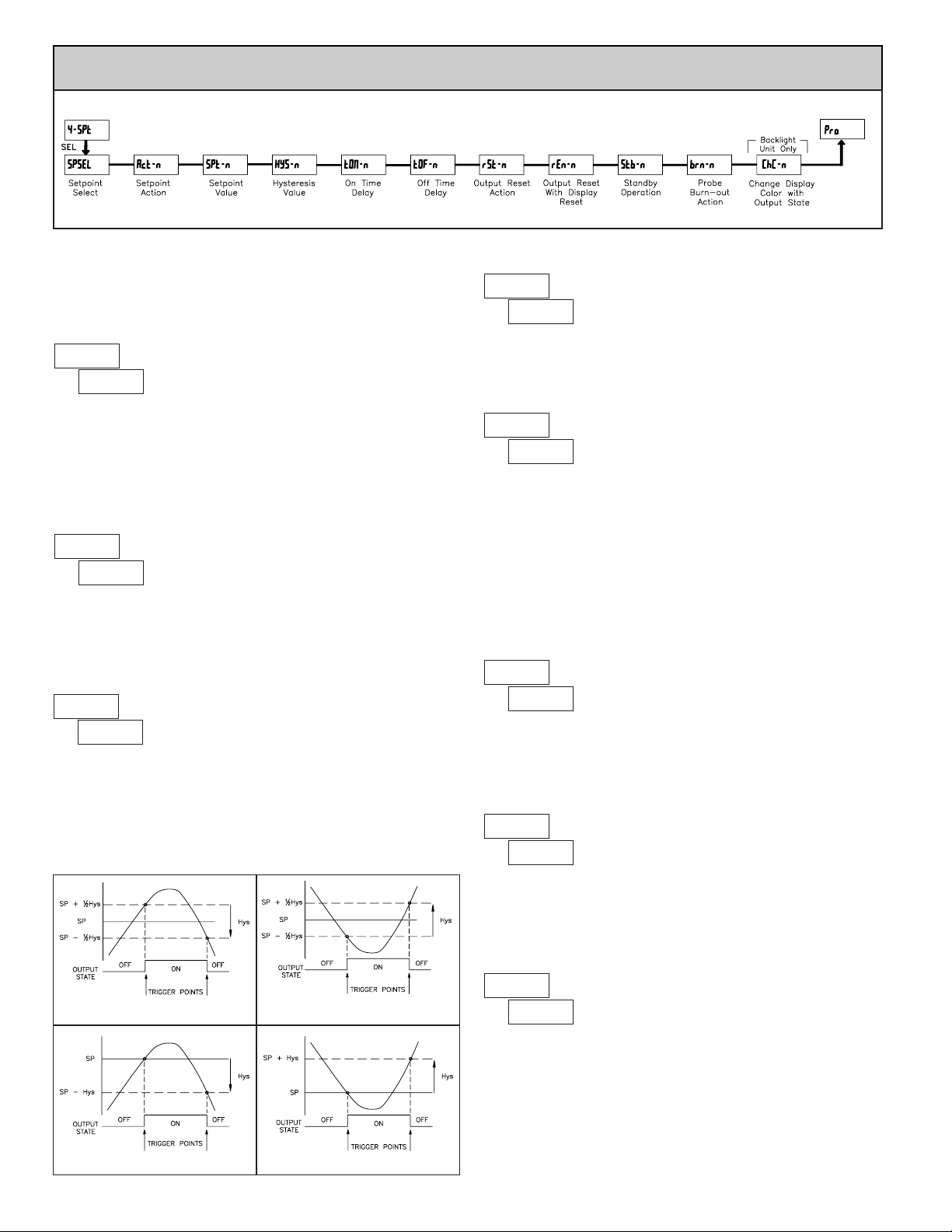
5.4 MODULE 4 - SETPOINT OUTPUT PARAMETERS (4-SPt)
PARAMETER MENU
The Setpoint Output Parameters are only active when an optional output
module is installed in the meter.
Enter the setpoint (output) to be programmed. The
n in the following
parameters will reflect the chosen setpoint number. After the chosen setpoint
is completely programmed, the display will return to
SPSEL. Repeat steps for
each setpoint to be programmed. Select
NO to exit the module. The number of
setpoints available is setpoint output card dependent.
SETPOINT SELECT
SP-2SP-1NO
ª
«
NO
SPSEL
Select YES to enable Setpoint 2 and access the setup parameters. If NO is
selected, the unit returns to
SPSELand setpoint 2 is disabled.
SETPOINT 2 ENABLE
NOYES
ª
«
NO
Enb-2
Enter the action for the selected setpoint (output). See Setpoint Output
Figures for a visual detail of each action.
SETPOINT ACTION
ª
«
HI-Ub
Act-n
ª
«
100
SPt-n
LO-UbHI-UbLO-bL
HI-bL
LO-Ub
=
HI-Ub
=
LO-bL
=
HI-bL
=
Low Acting, with unbalanced hysteresis
High Acting, with unbalanced hysteresis
Low Acting, with balanced hysteresis
High Acting, with balanced hysteresis
High Acting (Balanced Hys) = HI-bL
Low Acting (Unbalanced Hys) = LO-Ub
Low Acting (Balanced Hys) = LO-bL
High Acting (Unbalanced Hys) = HI-Ub
ª
«
2
HYS-n
HYSTERESIS VALUE
1 to 59999
Enter desired hysteresis value. See Setpoint Output Figures for visual
explanation of how setpoint output actions (balanced and unbalanced) are
affected by the hysteresis. When the setpoint is a control output, usually
balanced hysteresis is used. For alarm applications, usually unbalanced
hysteresis is used. For unbalanced hysteresis modes, the hysteresis functions on
the low side for high acting setpoints and functions on the high side for low
acting setpoints.
Note: Hysteresis eliminates output chatter at the switch point, while time delay
can be used to prevent false triggering during process transient events.
ª
«
0.0
tOF-n
ª
«
0.0
tON-n
OFF TIME DELAY
ON TIME DELAY
OUTPUT RESET ACTION
LAtCHAuto L-dLY
0.0 to 599.9 Sec
0.0 to 599.9 Sec
Enter the time value in seconds that the output is delayed from turning on
after the trigger point is reached. Avalue of 0.0 allows the meter to update the
output status per the response time listed in the Specifications.
Enter the time value in seconds that the output is delayed from turning off
after the trigger point is reached. Avalue of 0.0 allows the meter to update the
output status per the response time listed in the Specifications.
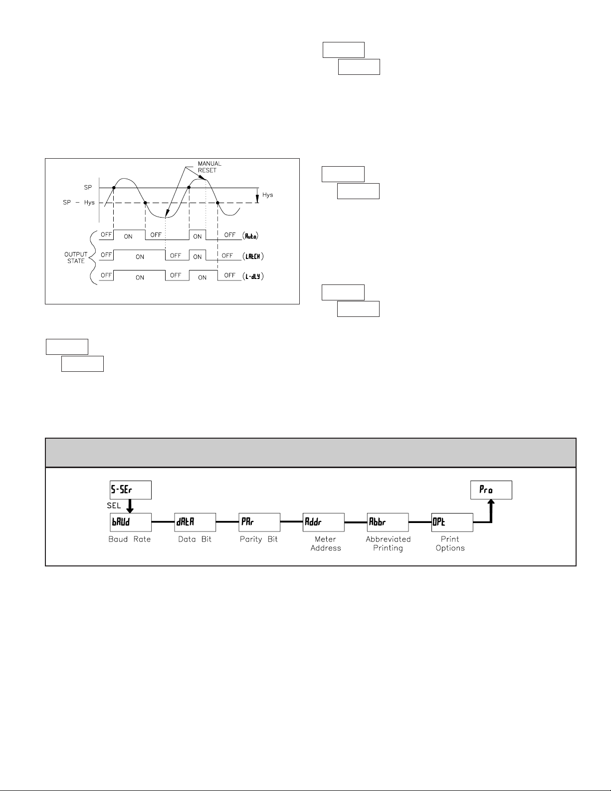
Enter the reset action of the output. See figure for details.
Auto = Automatic action; This action allows the output to automatically reset off
at the trigger points per the Setpoint Action shown in Setpoint Output
Figures. The “on” output may be manually reset (off) immediately by the
front panel RST button or user input.The output remains off until the trigger
point is crossed again.
LAtCH = Latch with immediate reset action; This action latches the output on at
the trigger point per the Setpoint Action shown in Setpoint Output Figures.
Latch means that the output can only be turned off by the front panel RST
button or user input manual reset, serial reset command or meter power cycle.
ª
«
Auto
rSt-n
Page 13
13
5.5 MODULE 5 - SERIAL SETUP PARAMETERS (
5-SSEr
)
Enter the probe burn-out action. In the event of a temperature probe failure
(open), the output can be programmed to be on or off.
PROBE BURN-OUT ACTION
ONOFF
This parameter enables the backlight DP63000 to switch the backlight
color when the output state changes. This parameter is only active for the
backlight version.
CHANGE DISPLAY COLOR w/OUTPUT STATE
YESNO
The Serial Setup Parameters are only active when the optional RS232 or RS485 serial communications module is installed in the meter. Refer to the DP6-COM
bulletin for complete details on DP63000 serial communications.
PARAMETER MENU
This parameter enables the RST button or user input to reset the output when
the display is reset.
Note: For this parameter to operate, the
RST button or User Input being used
must be set to
dSP and the Input value must be displayed. If these conditions are
not met, the output will not reset.
ª
«
YES
rEn-n
OUTPUT RESET WITH DISPLAY RESET
YESNO
When YES, the output is disabled (after a power up) until the trigger point is
crossed. Once the output is on, the output operates normally per the Setpoint
Action and OutputReset Action.
ª
«
NO
Stb-n
STANDBY OPERATION
YESNO
When the user input or RST button is activated (momentary action), the
corresponding “on” output is reset immediately and remains off until the
trigger point is crossed again. (Previously latched alarms will be off if power
up Display Value is lower than setpoint value.)
L-dLY = Latch with delay reset action; This action latches the output on at the
trigger point per the Setpoint Action shown in Setpoint Output Figures. Latch
means that the output can only be turned off by the front panel RST button
or user input manual reset, serial reset command or meter power cycle. When
the user input or RST button is activated (momentary action), the meter
delays the event until the corresponding “on” output crosses the trigger off
point. (Previously latched outputs are off if power up Display Value is lower
than setpoint value. During a power cycle, the meter erases a previous L-dLY
reset if it is not activated at power up.)
Setpoint Output Reset Actions
ª
«
NO
ChC-n
ª
«
OFF
brn-n
Page 14
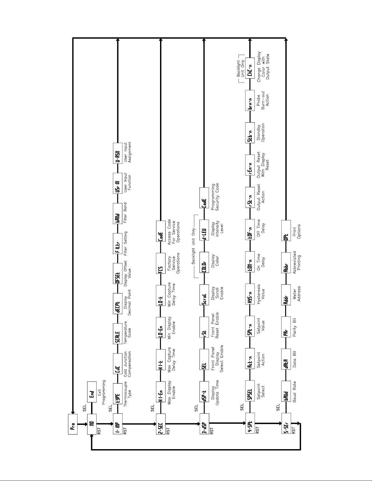
PROGRAMMING QUICK OVERVIEW
Press and hold SEL button
to enter Programming Mode.
Page 15

WARRANTY/DISCLAIMER
OMEGA ENGINEERING, INC. warrants this unit to be free of defects in materials and workmanship for a
period of 13 months from date of purchase. OMEGA’s WARRANTY adds an additional one (1) month grace
period to the normal one (1) year product warranty to cover handling and shipping time. This ensures
that OMEGA’s customers receive maximum coverage on each product.
If the unit malfunctions, it must be returned to the factory for evaluation. OMEGA’s Customer Service
Department will issue an Authorized Return (AR) number immediately upon phone or written request. Upon
examination by OMEGA, if the unit is found to be defective, it will be repaired or replaced at no charge.
OMEGA’s WARRANTY does not apply to defects resulting from any action of the purchaser, including but
not limited to mishandling, improper interfacing, operation outside of design limits, improper repair, or
unauthorized modification. This WARRANTY is VOID if the unit shows evidence of having been tampered
with or shows evidence of having been damaged as a result of excessive corrosion; or current, heat,
moisture or vibration; improper specification; misapplication; misuse or other operating conditions outside
of OMEGA’s control. Components in which wear is not warranted, include but are not limited to contact
points, fuses, and triacs.
OMEGA is pleased to offer suggestions on the use of its various products. However, OMEGA
neither assumes responsibility for any omissions or errors nor assumes liability for any
damages that result from the use of its products in accordance with information provided by
OMEGA, either verbal or written. OMEGA warrants only that the parts manufactured by the
company will be as specified and free of defects. OMEGA MAKES NO OTHER WARRANTIES OR
REPRESENTATIONS OF ANY KIND WHATSOEVER, EXPRESSED OR IMPLIED, EXCEPT THAT OF
TITLE, AND ALL IMPLIED WARRANTIES INCLUDING ANY WARRANTY OF MERCHANTABILITY
AND FITNESS FOR A PARTICULAR PURPOSE ARE HEREBY DISCLAIMED. LIMITATION OF
LIABILITY: The remedies of purchaser set forth herein are exclusive, and the total liability of
OMEGA with respect to this order, whether based on contract, warranty, negligence,
indemnification, strict liability or otherwise, shall not exceed the purchase price of the
component upon which liability is based. In no event shall OMEGA be liable for consequential,
incidental or special damages.
CONDITIONS: Equipment sold by OMEGA is not intended to be used, nor shall it be used: (1) as a “Basic
Component” under 10 CFR 21 (NRC), used in or with any nuclear installation or activity; or (2) in medical
applications or used on humans. Should any Product(s) be used in or with any nuclear installation or activity,
medical application, used on humans, or misused in any way, OMEGA assumes no responsibility as set forth
in our basic WARRANTY/DISCLAIMER language, and, additionally, purchaser will indemnify OMEGA and
hold OMEGA harmless from any liability or damage whatsoever arising out of the use of the Product(s) in
such a manner.
RETURN REQUESTS/INQUIRIES
Direct all warranty and repair requests/inquiries to the OMEGA Customer Service Department. BEFORE
RETURNING ANY PRODUCT(S) TO OMEGA, PURCHASER MUST OBTAIN AN AUTHORIZED RETURN (AR)
NUMBER FROM OMEGA’S CUSTOMER SERVICE DEPARTMENT (IN ORDER TO AVOID PROCESSING
DELAYS). The assigned AR number should then be marked on the outside of the return package and on any
correspondence.
The purchaser is responsible for shipping charges, freight, insurance and proper packaging to prevent
breakage in transit.
OMEGA’s policy is to make running changes, not model changes, whenever an improvement is possible. This affords our
customers the latest in technology and engineering.
OMEGA is a registered trademark of OMEGA ENGINEERING, INC.
© Copyright 2006 OMEGA ENGINEERING, INC. All rights reserved. This document may not be copied, photocopied,
reproduced, translated, or reduced to any electronic medium or machine-readable form, in whole or in part, without the
prior written consent of OMEGA ENGINEERING, INC.
FOR WARRANTY RETURNS, please have the
following information available BEFORE
contacting OMEGA:
1. Purchase Order number under which the product
was PURCHASED,
2. Model and serial number of the product under
warranty, and
3. Repair instructions and/or specific problems
relative to the product.
FOR NON-
WARRANTY REPAIRS, consult OMEGA
for current repair charges. Have the following
information available BEFORE contacting OMEGA:
1. Purchase Order number to cover the COST of the
repair,
2. Model and serial number of the product, and
3. Repair instructions and/or specific problems
relative to the product.
Page 16

Where Do I Find Everything I Need for
Process Measurement and Control?
OMEGA…Of Course!
Shop online at omega.com
TEMPERATURE
] Thermocouple, RTD & Thermistor Probes, Connectors, Panels & Assemblies
] Wire: Thermocouple, RTD & Thermistor
] Calibrators & Ice Point References
] Recorders, Controllers & Process Monitors
] Infrared Pyrometers
PRESSURE, STRAIN AND FORCE
] Transducers & Strain Gages
] Load Cells & Pressure Gages
] Displacement Transducers
] Instrumentation & Accessories
FLOW/LEVEL
] Rotameters, Gas Mass Flowmeters & Flow Computers
] Air Velocity Indicators
] Turbine/Paddlewheel Systems
] Totalizers & Batch Controllers
pH/CONDUCTIVITY
] pH Electrodes, Testers & Accessories
] Benchtop/Laboratory Meters
] Controllers, Calibrators, Simulators & Pumps
] Industrial pH & Conductivity Equipment
DATA ACQUISITION
] Data Acquisition & Engineering Software
] Communications-Based Acquisition Systems
] Plug-in Cards for Apple, IBM & Compatibles
] Datalogging Systems
] Recorders, Printers & Plotters
HEATERS
] Heating Cable
] Cartridge & Strip Heaters
] Immersion & Band Heaters
] Flexible Heaters
] Laboratory Heaters
ENVIRONMENTAL
MONITORING AND CONTROL
] Metering & Control Instrumentation
] Refractometers
] Pumps & Tubing
] Air, Soil & Water Monitors
] Industrial Water & Wastewater Treatment
] pH, Conductivity & Dissolved Oxygen Instruments
M4483/0607
 Loading...