

Page 1
TM
User’s Guide
Shop online at
omega.com
e-mail: info@omega.com
For latest product manuals:
www.omegamanual.info
Universal 6/12 Channel ¼ DIN Panel Meter
DP606A/DP612A
Page 2

omega.com info@omega.com
Servicing North America:
Omega Engineering, Inc.
U.S.A.
800 Connecticut Ave, Suite 5N01
Headquarters:
Norwalk, CT 06854 USA
Toll-Free: 1-800-826-6342 (USA & Canada only)
Customer Service: 1-800-622-2378 (USA & Canada only)
Engineering Service: 1-800-872-9436 (USA & Canada only)
Tel: (203) 359-1660 Fax: (203) 359-7700
e-mail: info@omega.com
For Other Locations Visit omega.com/worldwide
The information contained in this document is believed to be correct, but OMEGA accepts no liability for any errors it contains, and reserves
the right to alter specifications without notice.
Page 3

Table of
Contents
DP600A, DP606A, DP612A Series
Table of Contents
Section ..................................................................................... Page
Section 1 Introduction .................................................................................... 1
Section 2 Installation and Operating Conditions ..................................... 2
Section 3 Mounting Instructions .................................................................. 3
Section 4 Wiring Instructions ....................................................................... 4
4.1 Rear Panel Diagram ................................................................. 4
4.2 Connecting Power .................................................................... 5
4.3 Connecting Alarms .................................................................. 6
4.4 Connecting Communications ................................................ 7
4.5 Connecting Inputs .................................................................... 7
Section 5 Navigation ....................................................................................... 8
5.1 RUN Mode ................................................................................. 8
5.2 Lock Zones ................................................................................. 9
5.3 Clear Alarms ............................................................................. 9
5.4 Check Alarm Values ................................................................ 9
5.5 Function Select Mode ............................................................... 9
5.6 Reset Defaults ........................................................................... 9
5.7 Function Select Mode ............................................................ 10
5.8 Function 1-Enter Password .................................................. 11
5.9 Function 2-Set Active Zones ................................................ 11
5.10 Function 3 and 4-Set Low and High Alarms .................... 12
5.11 Function 5-Modbus Address ............................................. 13
5.12 Function 6-Set Scan Time ................................................... 13
5.13 Function 7-Set Device Configuration ......................... 14-15
5.14 Function 8-Password Enable/Disable ............................... 16
5.15 Function 9-Calibration ........................................................ 16
5.16 Function A/B-Alarm Relay Function ................................ 17
5.17 Function C/D-Scaling .......................................................... 18
5.18 Function F-Serial Configuration ....................................... 19
Section 6 Serial Interface ............................................................................. 20
6.1 Modbus Functions .................................................................. 20
6.2 Data Formats ........................................................................... 21
6.3 Multiple Register Reads ....................................................... 21
6.4 Multiple Register Writes ...................................................... 22
6.5 Request Packet Sizes ............................................................. 22
Page 4

Table of Contents
Section ..................................................................................... Page
Table of
DP600A, DP606A, DP612A Series
Contents
Section 7 Modbus Register Assignments ................................................. 23
7.1 System Registers ..................................................................... 23
7.2 Temperature Registers .......................................................... 24
7.3 Status Registers ...................................................................... 24
7.4 Zone Registers ........................................................................ 25
7.5 User Calibration ...................................................................... 26
7.6 Enumerated Values ............................................................... 26
7.7 Sensor Type ............................................................................. 26
7.8 RTD Type ................................................................................. 26
7.9 Thermocouple Type .............................................................. 27
7.10 Sensor Status ......................................................................... 27
7.11 System State .......................................................................... 27
7.12 Process Unit .......................................................................... 28
7.13 Alarm Type ............................................................................ 28
7.14 Alarm Status ......................................................................... 28
7.15 Setting Toggle ....................................................................... 28
Section 8 Specifications ................................................................................ 29
8.1 Alarm Relays ........................................................................... 29
8.2 Input Accuracy ....................................................................... 30
Section 9 Approvals Information ............................................................... 31
Page 5

Table of
Contents
DP600A, DP606A, DP612A Series
Table of Figures and Tables
Figures ..................................................................................... Page
Figure 1 Side and Panel Cutout Views ...................................................... 3
Figure 2 DP606A/DP612A: Rear Panel Connections ............................... 4
Figure 3 Main Power Connections ............................................................. 5
Figure 4 Relay Connections ......................................................................... 6
Figure 5 3 Wire RTD Wiring Diagram ....................................................... 7
Figure 6 Front Panel Diagram ..................................................................... 8
Figure 7 Process Input Scaling .................................................................. 18
Table ........................................................................................ Page
Table 1 Rear Panel Connections ................................................................ 4
Table 2 9 Pin Input Power/Relay Wiring Summary .............................. 5
Table 3 Connecting Communications ...................................................... 7
Table 4 Function Codes ............................................................................. 10
Table 5 Device Configuration .................................................................. 14
Table 6 Alarm Relay Configuration ....................................................... 17
Table 7 Serial Port Configuration ........................................................... 19
Table 8 Modbus Functions ....................................................................... 20
Table 9 Mulitple Register Writes ............................................................ 22
Table 10 Packet Sizes ................................................................................... 22
Table 11 System Registers .......................................................................... 23
Table 12 Temperature Registers ................................................................ 24
Table 13 Sensor Status Registers ............................................................... 24
Table 14 Zone Registers .............................................................................. 25
Table 15 User Calibration ........................................................................... 26
Table 16 Input Accuracy ............................................................................. 30
Page 6

1
Introduction
Section 1 - Introduction
The DP606A/DP612A Display Meter offers a flexible, easy to use 6 or 12 zone, 4 digit
temperature and process measurement solution in a rugged ¼ DIN Aluminum
housing. Selectable configuration eliminates the need for jumpers.
The DP606A supports 6 independent zones and the DP612A supports up to 12 zone
(3 wire RTD limited to 6 zones on all models). All zones are scanned at a 400ms rate.
The display shows the reading of each zone sequentially. High and low Alarms with
SPDT relay outputs are available for monitoring and alarm purposes.
The universal input supports 9 thermocouple types (J, K, T, E, R, S, B, C, and N), 2 or
3 wire RTDs (Pt 100, Ni 120, Cu 10), DC voltage (0-1 Vdc), or DC current (0 – 24 mA).
Independent alarms are available for each zone. Each alarm can be configured for
above (HI), below (LO) or HI/LO triggering. Alarms conditions will be indicated on
the display meter and may be used to activate either of the 2 SPDT relay outputs.
A user selectable RS232 or RS485 serial port interface is standard on all models and
uses the Modbus RTU protocol for configuration management and data transfer.
The universal AC power supply accepts 90–240 Vac. The isolated DC power option
accepts 9–36 Vdc.
A security password can be used to prevent front panel tampering of the
configuration.
1
Page 7

Installation and Operating Conditions
Section 2 - Installation and Operating Conditions
This Instrument is marked with the international Caution symbol. It is important to
read and follow the Setup Guide before installing or commissioning this device. The
Guide contains important information relating to safety and EMC.
The instrument is a device protected in accordance with UL 61010:2010 Electrical
Safety Requirements for Electrical Equipment for Measurement, Control and
Laboratory. The device has no power-on switch. Installations must include a switch
or circuit breaker that is compliant to IEC 947-1 and 947-3. It must be suitably
located to be easily reached and marked as the disconnecting device for the
equipment.
WARNING: Do NOT connect AC power to your device until you have completed
all input and output connections. This device is a panel mount device protected in
accordance with Class I of EN 61010 (115/230 AC power connections), Class III for
the DC power option (9-36Vdc). It must be installed by a trained electrician with
corresponding qualifications. Failure to follow all instructions and warnings may
result in injury.
Use Copper conductors only, minimum 20 AWG, UL Rated, for power and outputs.
Insulation must be rated for at least 85ºC and 600V.
2
This device is not designed for use in, and should not be used for, patient-connected
applications.
Safety:
EMC:
WARNING: Failure to follow all instructions and warnings is at your own risk and
may result in property damage, bodily injury and/or death. Omega Engineering
is not responsible for any damages or loss arising or resulting from any failure to
follow any and all instructions or observe any and all warnings.
• Do not exceed the voltage rating on the label located on the device housing.
• Always disconnect power before changing signal and power connections.
• Do not operate this instrument in flammable or explosive atmospheres.
• Do not expose this instrument to rain or moisture.
• Whenever EMC is an issue use shielded cables.
• Never run signal and power wires in the same conduit.
• Use signal wire connections with twisted-pair cables.
• If EMC problems occur Install Ferrite Bead(s) on signal wires close to the
instrument.
CAUTION: Risk of electric shock. Disconnect all power sources before servicing.
2
Page 8
3
Pane l
Bezel
Cas e Slide Sc re w
SideView
User
Acce ssible
BehindPanel
PanelCutout
92mm
92mm
Mounting Instructions
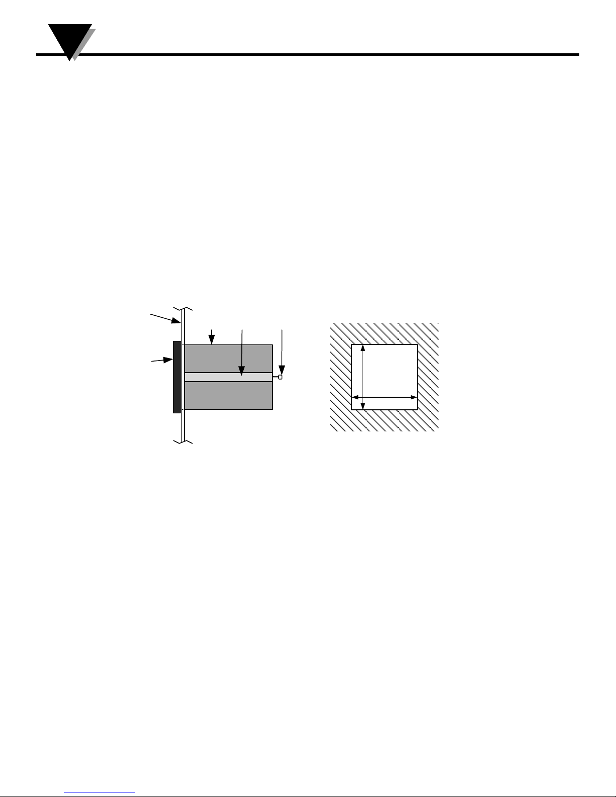
Section 3 - Mounting Instructions
Select a location for the monitor that is free from excessive shock, vibration, dirt,
moisture and oil. Mount the monitor into a 3 5/8” (92mm) square cutout. The
monitor as shipped is 1/4 DIN (92mm square), so it does not have to be removed
from its housing to be mounted. Remove the two screws that secure the mounting
slides. Remove the slides and insert the case into the cutout from the front side of
the panel. Reinstall the two slides and two screws. The length of the slides must be
reduced if the monitor is to be mounted in an extra thick panel.
Ensure that the unit is properly grounded to the panel which should be earth
grounded. Use the supplementary ground point indicated on the rear panel if a
good ground connection cannot be maintained from the mounting slides alone.
Figure 1 - Side and Panel Cutout Views
3
Page 9
1
2
3
4
5
6
19
13
1 12
7
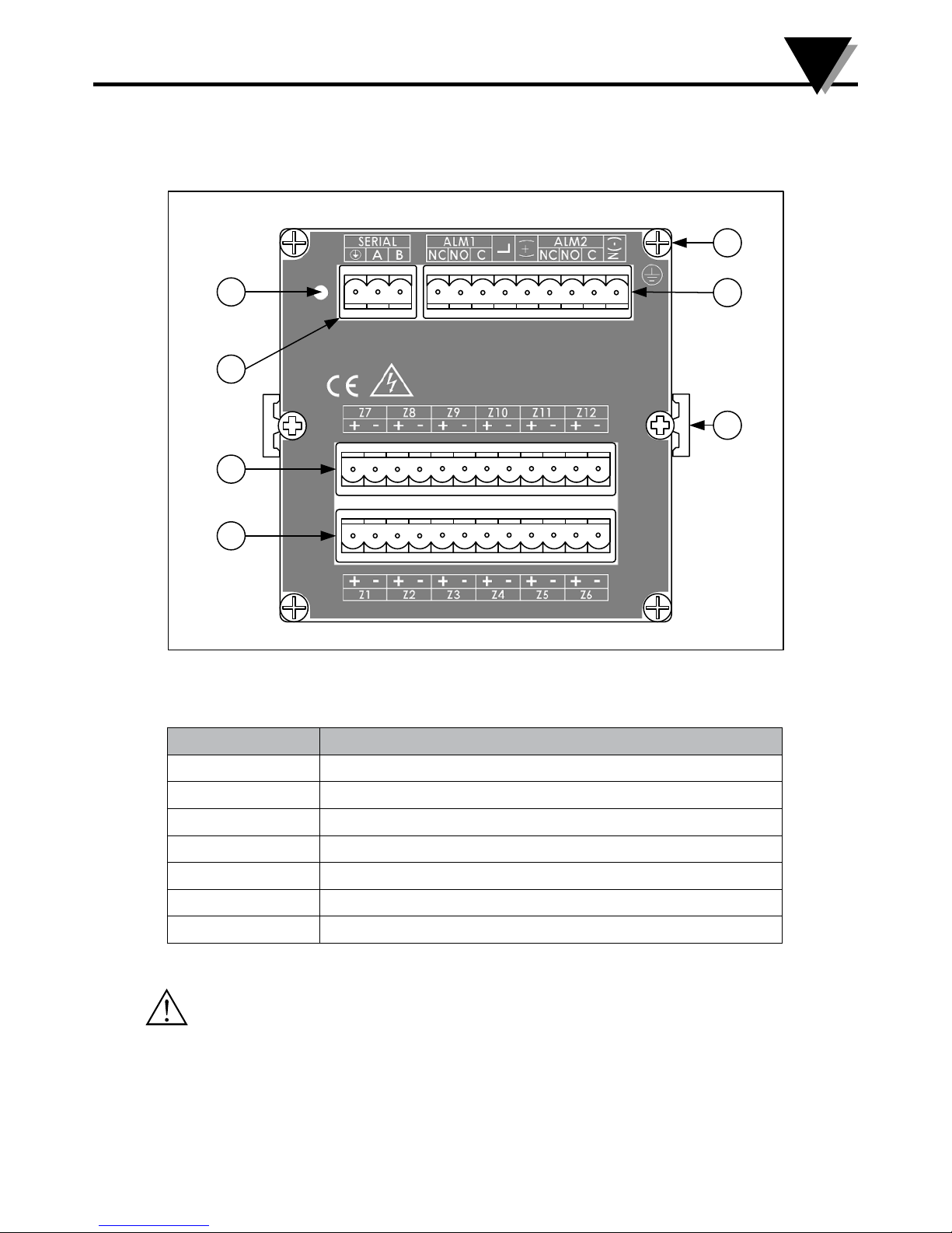
Section 4.1 - Rear Panel Diagram
Wiring Instructions
4
Figure 2 - DP606A/DP612A: Rear Panel Connections
Item Description
1 Reset Pinhole
2 Serial Connector
3 Input 7 through 12
4 Input 1 through 6
5 Supplementary Ground Point
6 Power and Alarm Connector
7 Mounting Slide
Caution: Use only provided terminals. Torque all connections to 0.5-0.6Nm.
Table 1 - Rear Panel Connections
4
Page 10
4
NC
L
ALM1
NO C
(+)
N(-)
NC
ALM2
NO C
19
N
L
SW
Fuse
SW
+
-
Or
DCPOWEROPTION
90–240Vac
9–36Vdc
ACP O WER
Fuse
Wiring Instructions
Section 4.2 - Connecting Power
Pin No. Code Description
1 N(-) Neutral Power / DC-Power supply
2 ALM2 C Alarm Relay 2 Common
3 ALM2 NO Alarm Relay 2 Normally Open
4 ALM2 NC Alarm Relay 2 Normally Closed
5 (+) DC + Power supply (9-36 VDC)
6 L Line Power (90-240 VAC)
7 ALM1 C Alarm Relay 1 Common
8 ALM1 NO Alarm Relay 1 Normally Open
9 ALM1 NC Alarm Relay 1 Normally Closed
Table 2 - 9-Pin Input Power/Relay Wiring Summary
Connect the main power connections to pins 4 and 9 (AC Power) or pins 5 (+) and 9
(-) (DC Power) of the 9pin power / output connector as shown in Figure 3.
Figure 3 - Main Power Connections
For the low-voltage power option, maintain the same degree of protection as the
standard high-voltage input power units (90–240 Vac) by using a Safety Agency
Approved DC source with the same Overvoltage Category and pollution degree as
the AC model.
The Safety European Standard EN61010-1 for measurement, control, and laboratory
equipment requires that fuses must be specified based on IEC127. This standard
specifies the letter code “T” for a Time-lag fuse.
5
Page 11
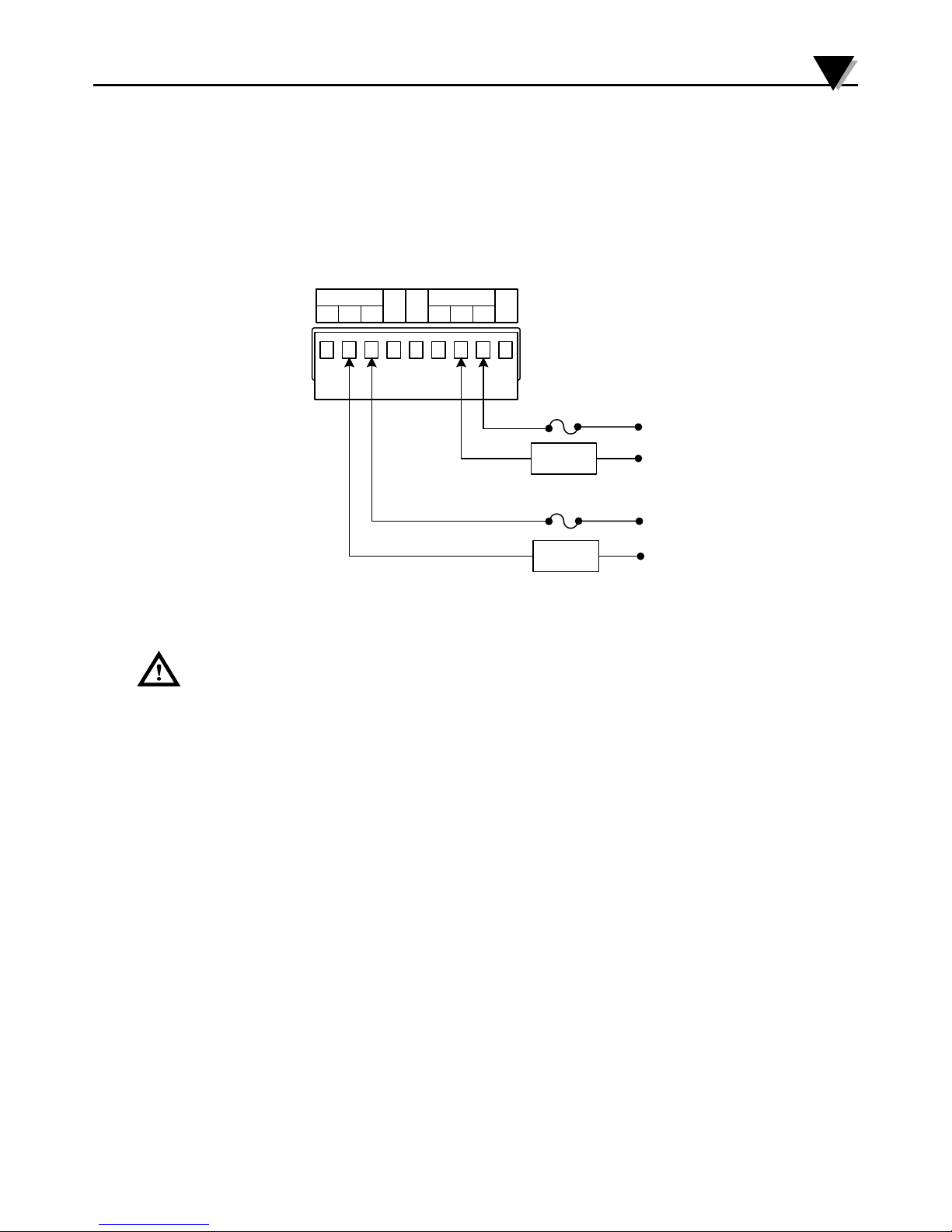
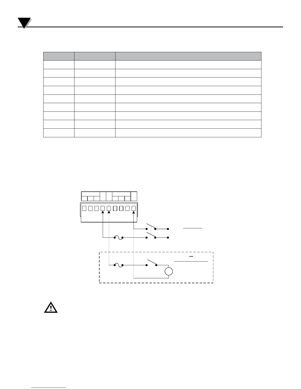
Section 4.3 - Connecting Alarms
NC
L
ALM1
NO C
(+)
N(-)
NC
ALM2
NO C
19
Fuse
Fuse
Lo ad
Load
The DP606A/DP612A Series includes SPDT mechanical relays with internal
snubbers on the normally open contact side. When powered and not in an alarm
state the relays are Energized and the NO contact is connected to the Relay
common contact. If an alarm condition occurs or if the unit loses power the relay is
deenergized and the NC contact is connected to the Relay common contact.
Wiring Instructions
4
Figure 4 - Relay Connections
WARNING: For the low-voltage power option, maintain the same degree of
protection as the standard high-voltage input power units (90–240 Vac) by using a
Safety Agency Approved DC or AC source with the same Overvoltage Category and
pollution degree as the standard AC unit (90–300 Vac).
The Safety European Standard EN61010-1 for measurement, control, and laboratory
equipment requires that fuses must be specified based on IEC127. This standard
specifies the letter code “T” for a Time-lag fuse.
6
Page 12

4
+ -Z1+ -Z2+ -Z3+ -Z4+ -Z5+ -
Z6
+ - + - + - + - + - + -
Z7 Z8 Z9 Z10 Z11 Z12
Wiring Instructions
Section 4.4 - Connecting Communications
Pin No. Code Description
1 B RS485 B signal, RS232 TX (to remote device)
2 A RS485 A signal, RS232 RX (from remote device)
3 RTN signal for serial communications
Table 3 - Connecting Communications
Note: The RTN signal is isolated from the Signal RTN and the Power GND.
Section 4.5 - Connecting Inputs
Connect Input sensors to the terminals Marked Zone 1 though Zone 12 (Z1 – Z12) on
the rear panel. For the DP606A only Zones 1 through 6 are active and Terminals Z7
– Z12 are only used for 3 Wire RTDs. When connecting sensors follow the polarity
indicated on the rear panel. For Thermocouples the Negative wire is Red (NA) or
White (IEC 584-3). For Process Inputs the Negative terminal is ground.
For the RTD 3 wire option the common wires must be connected to the + terminals
of both the upper (Z1 – Z6) and lower (Z7 – Z12) input boards. The negative terminal
of Z7- Z12 remains unconnected. If a 2 wire RTD needs to be used in 3 Wire mode
use a jumper wire to connect the upper and lower terminals together. Refer to the
wiring diagram below.
Note that all negative input terminals share a common internal ground connection.
Ensure that all sensors share a common ground or are fully isolated.
Figure 5 - 3 Wire RTD Wiring Diagram
7
Page 13

Section 5 - Series Navigation
ºC
ºF
mA
mV
Function Zone
1
2
3
7
6
5
4
Series Navigation
5
Item Description
1 Main Display
2 Function Display
3 Advance Button
4 Increment Button
5 Select Button
6 Zone Display
7 Unit/Mode Indicator
Section 5.1 - RUN Mode
When power is applied to the unit it will automatically enter the RUN mode,
sequentially scanning each active zone and activating alarms if required. The Main
display shows the measured value of the indicated zone. The unit will change to
each active zone in sequence the user determined rate.
While in the RUN mode the user may lock the display at the current zone, clear any
latched alarms, examine the current Alarm values or enter the PROGRAMMING
mode.
Figure 6 - Front Panel Diagram
8
Page 14

5
Series Navigation
Section 5.2 - Lock Zones
Symbol Description
The display stops cycling thru each display. The currently selected
zone information will be continuously updated on the display. Note
that all active zones continue to be read and any alarm conditions
will activate the enabled alarm relays.
The Lock option is released and the value display will cycle thru all
active zones.
Section 5.3 - Clear Alarms
Any active, latched alarm is cleared.
Section 5.4 - Display Alarm Values
Displays the Alarm Value for the current zone and stops scanning.
The Main display shows the Alarm value. The Zone display shows
the zone.
Increments the Zone number and displays the next
Alarm Value.
Switches between HI and LO Alarm Values. The Function
display shows 3 when displaying Low values and 4 when
displaying High Values.
Return to Run Mode
Section 5.5 - Function Select Mode
Enter Function Select Mode from Run Mode
Section 5.6 - Reset Defaults
Hold all 3 buttons down for 5 seconds to reset unit to Factory
Defaults. The unit will reboot and return to Run Mode.
9
Page 15

Section 5.7 - Function Select Mode
While in function select mode 1 is displayed in the Function Display and the
selected function is displayed in the Main display.
The DP606A/DP612A monitor has several different Functions listed in the table
below.
Function Description
0 Return to Run Mode
1 Function Select / Enter Password
2 Set Active Zone
3 Set Low Alarms
4 Set High Alarms
5 Set Modbus Address
6 Set Scan Time
7 Set Model Options
Series Navigation
5
8 Password Enable and Disable
9 Calibration
A Set Alarm 1 Options
B Set Alarm 2 Options
C Set Low Scale
D Set High Scale
F Set Serial Options
Table 4 - Function Codes
Navigate Function Select Mode using the button below.
Increments the Function Code displayed in the
Main display.
Enters the Function displayed in the Function
display.
If the Password option is enabled only Functions 0 and 1 will be available. Entering
the correct password in Function 1 will unlock the rest of the menu options. If the
Password is disabled Function 1 will not be available.
10
Page 16

5
ºC
ºF
mA
mV
Function Zone
Series Navigation
Section 5.8 - Function 1 - Enter Password
A password may be enabled to prevent unintended changes to the unit. The
password is a 4 digit code and the default Password is 1011. The password can only
be changed using the serial port.
Use the buttons below to enter the password.
Increment the flashing digit of the Main display
Selects the next digit of the Main display, causing it to flash
Enters the Password
After entering the password the unit will return to function select mode. If the
password is correct all of the functions will be available. If the password was entered
incorrectly it must be re-entered by selecting Function 1 again.
Section 5.9 - Function 2 - Set Active Zones
The main display is blank when selecting active zones. The current zone being
edited is shown in the Zone Display. Active zones are displayed solid while disabled
zones are displayed flashing. By default all zones are active.
Disabled zones are skipped while scanning and do not generate alarms. Use the
buttons below to change the active zone.
Advance to the next zone.
Toggles the current zone between enabled (solid) or disabled
(flashing).
Stores the enabled / disabled state for all zones and returns to
Function Select mode
11
Page 17

Section 5.10 - Function 3 and 4 - Set Low and High Alarms
ºC
ºF
mA
mV
Function Zone
The High and Low alarm values determine the readings that the Alarms will
activate at for each zone. The function selected is indicated in the function display.
Function 3 sets the low alarms and Function 4 sets the high alarms. The default Low
alarm is -900 and the default High alarm is 9000 for all zones.
The alarms for each zone are independent. The zone for the current alarm being
edited is shown in the zone display.
The current alarm value for the selected zone is shown in the main display. The left
most digit blinks indicating it can be edited. Use the buttons indicated below to edit
the alarm values.
Series Navigation
5
Increment the flashing digit of the VALUE display.
Selects the next digit of the VALUE display, causing it to flash.
Changes the decimal point.
Stores the current VALUE display as the alarm value for the
current zone and advances to the next zone.
Stores all values and returns to Function Select mode.
12
Page 18

ºC
ºF
mA
mV
Function Zo ne
5
ºC
ºF
mA
mV
Function Zo ne
Series Navigation
Section 5.11 - Function 5 - Set Modbus Address
The Modbus address is used for serial communications to determine which device
on a bus is being accessed. The current Modbus Address is shown in the Main
Display. The first digit flashes to indicate it can be edited. Use the buttons below to
edit the address.
By Default the Modbus address is 1 and any address from 1 to 247 can be used. The
unit will not allow an invalid address to be displayed. Trying to enter a number
greater than 247 will cause the display to roll back to a valid number.
Increment the flashing digit of the Main display.
Selects the next digit of the Main display, causing it to flash.
Stores the Device address and returns to the Function Select
mode.
Section 5.12 - Function 6 - Set Scan Time
The scan time is the time each zone is displayed on the front panel before advancing
to the next zone. By Default, the scan time is 3 seconds. The current scan time is
displayed in the Main Display and the zone display is blank. The left most digit
blinks indicating it can be edited. Use the buttons below to edit the scan time.
Increment the flashing digit of the VALUE display.
Selects the next digit of the VALUE display, causing it to flash.
Stores the current VALUE display as the SCAN time and returns
to the Function Select mode.
13
Page 19

Section 5.13 - Function 7 - Set Device Configuration
ºC
ºF
mA
mV
Function Zone
Function 7 sets the device configuration including the Alarm Type, Units and input
type. The default setting for Function 7 is 2204 which represents Thermocouple
Type K inputs with High/Low Latching alarms in Degrees Celsius.
Each digit in the Main Display represents a different function. Refer to the table
below for the specific functions.
Series Navigation
5
Digit 1 Digit 2 Digit 3 Digit 4
Alarm
Type
Unit
Alarm
Latch
Input Type
TC
Type
RTD
Type
Decimal
Points
0 High 0 C Latching 0 TC 0 B Pt100 0
1 Low 1 F Latching 1 RTD2 1 C Ni120 1
2 High/
Low
3 Off 3 F Non-
2 C Non-
Latching
2 RTD3 2 E Cu10 2
3 mA 3 J 3
Latching
4 User 4 mV 4 K
5 R
6 S
7 T
8 N
Please note: Digit 4 is dependent upon the “Input Type” selected under Digit 3. Ex: If “TC” is selected under “Input Type” under Digit 3, Digit
4 becomes one of the following “B, C, E, J, etc.” under “TC Type.”
Table 5 - Device Configuration
14
Page 20

5
Series Navigation
Section 5.13 - Function 7 - Set Device Configuration cont.
Digit 1 is the Alarm type. High alarms will deactivate the relay when the Zone
process value is Above the High Alarm Value defined in Function 4. Low alarms will
deactivate the relay when the Zone process value is below the Low alarm defined in
Function 3. High/Low will trigger on both alarms and Off will not trigger alarms at
all. If different operation is desired for Relay 1 and Relay 2 or if different alarm types
need to be used per zone these can be setup in Functions A and B by selecting
User controlled.
Digit 2 defines the Units displayed for TC and RTD inputs. It also selects between
Latching and Non-Latching alarms. Latching alarms will remain active until the
latch is cleared by the user regardless of the current input value. Non-latching
alarms will deactivate as soon as the input no longer meets the alarm conditions.
The Alarm Latch Type is overwritten by the User settings if user is selected for the
Alarm Type.
Digit 3 selects between the available input types. The input type cannot be changed
individually per zone. When selecting RTD 3 wire input only 6 zones will be active
on a 12 Zone unit.
Digit 4 is context sensitive and depends on Digit 3. If TC or RTD type input are
selected Digit 4 selects the type of sensor. If mV or mA type input are selected
Digit 4 represents the maximum number of decimal points that will be displayed.
If all decimal points cannot be displayed the display will be rounded to the nearest
displayable number. Temperature readings can only be displayed to the nearest
whole number.
Increment the flashing digit of the VALUE display.
Selects the next digit of the VALUE display, causing it to flash.
Stores the current VALUE display as the Input Type advances
to the next zone. Note that this button will have no effect if the
VALUE display is selecting an invalid input type.
15
Page 21

Section 5.14 - Function 8 - Password Enable/Disable
ºC
ºF
mA
mV
Function Zo ne
ºC
ºF
mA
mV
Function Zone
Using Function 8, a user password may be enabled to protect the unit from
inadvertent changes. By Default the Password is disabled.
The default password is 1011. This can only be changed using the serial port.
Toggle the password from enabled (1) and disabled (0)
Stores the current VALUE display as the password enabled
state and returns to the Function Select mode.
Series Navigation
5
Section 5.15 - Function 9 - Calibration
The DP600A and DP612A are factory calibrated and do not require additional user
calibration under most circumstances. For 2 wire RTDs Function 9 may be used to
calibrate out lead wire resistance. This calibration is done independently for each
channel.
To perform lead wire calibration short the RTD that needs to be calibrated at the
end of the lead wire. Next select the Zone to be calibrated in the primary Display
using the increment button. Press the select button to perform the calibration. While
the unit is calibrating the Zone flashes to indicate it is busy. Once the calibration
is complete the Zone will stop flashing. If the lead wire resistance is more than 10
ohms the unit will display “FAIL” and the calibration value will be set to 0.
Scroll to next zone
Perform Calibration on current zone
Returns to Function Select mode
16
Page 22

ºC
ºF
mA
mV
Function Zo ne
5
Series Navigation
Section 5.16 - Function A/B - Alarm Relay Function
When split operation is selected in Function 7, Alarm relay operation is customized
using functions A and B.
Function A Controls Alarm 1 and Function B controls Alarm 2. Each zone may be
assigned to one or more relays. By Default, Alarm 1 is assigned high / low alarms
for all zones and Alarm 2 is Disabled for all zones. The Current Zone being edited is
shown in the Zone Display. The current mode for that zone is displayed in the Main
Display.
Increment the flashing digit of the VALUE display
Selects the next digit of the VALUE display, causing it to flash
Moves to the next zone
Stores all values and returns to Function Select mode
Digit 1 Digit 2
Alarm Latching Alarm Type
0 Not Latched 0 High Alarm
1 Latching relay 1 Low Alarm
2 High and Low Alarm
3 Alarm Disabled
Table 6 - Alarm Relay Configuration
17
Page 23

Section 5.17 - Function C/D - Scaling
ºC
ºF
mA
mV
Function Zone
C
D
InputCurrent/Voltage
Functions C and D set the scaling for the mA and mV input. Function C sets the
Low Scale and Function D sets the High Scale. The scaling factors for mA and mV
are separate so the values corresponding to the input type selected in Function 7 are
shown.
By default the scaling is set to display the measurement in mA/mV.
Scaling factors are applied independently for each zone. The current zone being
modified is displayed in the Zone Display. Enter the value to be displayed at 4mA or
0V in Function C and the value to be displayed at 20mA or 1V in function D. Values
between the two points are linearly interpolated.
Series Navigation
5
Increment the flashing digit
Selects the next digit, causing it to flash
Changes the decimal point
Stores the current scaling factor for the indicated zone
advances to the next zone.
Stores all values and returns to Function Select mode
Figure 7 - Process Input Scaling
18
Page 24

5
Series Navigation
Section 5.18 - Function F - Serial Configuration
Function F sets up the serial port of the device. The default serial settings are RS485,
115.2k baud no Parity.
Increment the flashing digit on the display
Selects the next digit of the VALUE display, causing it to flash.
Stores the current VALUE display as the Serial configuration and
returns to the Function Select mode. This button will have no effect if the current VALUE is does not match a valid configuration.
Digit 1 Digit 2 Digit 3 Digit 4 (LSD)
Signaling Type Baud Rate Parity
0 RS485 0 4800 0 None 0 Reserved
1 RS232 1 9600 1 Odd
2 19200 2 Even
3 38400
4 57600
5 115200
Table 7 - Serial Port Configuration
19
Page 25

Section 6 - Serial Interface
The DP606A and DP612A uses the Modbus/RTU interface as described in MODBUS
APPLICATION PROTOCOL SPECIFICATION (V1.1b3).
The Modbus specification allows accessing to up 65535 internal ‘holding’ registers
using register READ, register WRITE and WRITE MULTIPLE commands. Each
Modbus holding register is defined as a 16 bit entity structured as BIG ENDIAN
values (most significant byte always presented first).
Modbus is structured using a MASTER-SLAVE topology, in which there is one
MASTER device and up to 247 slave devices. All transactions are initiated by the
MASTER device. The DP606A and DP612A acts as a slave device, with a device
address in the range 1 to 247.
Modbus slave devices are individually accessed using a one byte SLAVE address.
The MASTER device initiates a transaction by sending a request packet to a specific
slave. The SLAVE device processes the transaction and returns either response
packet indicating success or failure.
Address 0 is reserved as a ‘broadcast’ address, in which all slave devices will accept
and process the transaction but will not send a response.
Serial Interface
6
Section 6.1 - Modbus Functions
The DP606A and DP612A Modbus interface supports the following Modbus
FUNCTION requests.
Function Code Mnemonic Description
0x03 Read Holding Register Reads one or more consecutive 16 bit
holding registers
0x06 Write Single Register Writes a specific 16 bit holding register
0x07 Read Exception status Reads structured status information
0x08 Reserved
0x10 Write Multiple Registers Write one or more consecutive 16 bit
holding registers
0x0b Get Comm events Read communication event counters
Table 8 - Modbus Functions
20
Page 26

6
Serial Interface
Section 6.2 - Data Formats
Modbus holding registers are represented as 16 bit entities. The following encoding
is used for extended data items. Note that ‘byte 0’ will be the first byte received/
transmitted.
For data types that can be represented in 16 bits (Boolean, byte, char, int16 and
uint16) a single register is used.
For data types that require 32 bits two consecutive registers are used. The lower
number register will represent the most significant data. The 2nd register represents
the leas significant data.
Section 6.3 - Multiple Register Reads
When reading a dual register entity the lower order register should be used as the
requested ‘holding register’, with a request for a minimum of 2 registers. Internally
the entire entity is read and data is then built into a response packet.
The access can be split into 2 consecutive single register reads. When the lower
(base) register is accessed the entire 32 bit entity is read and the two most
significant bytes are returned. The following single register read must specify the
next consecutive register address. The two least significant bytes of the internally
buffered data used in the response.
Attempts to access the two least significant bytes without first reading the two most
significant bytes will result in an error response.
21
Page 27

Section 6.4 - Multiple Register Writes
When writing a dual register entity the lower order register should be used as the
requested ‘holding register’, with a request for minimum of 2 registers. The write
data is internally buffered and transferred to the database entry as a 32-bit value.
The access can be split into 2 consecutive single register writes. When the lower
(base) register is written the 16-bit entity is internally buffered BUT NO DATA
TRANSFER IS MADE TO THE DATABASE. The following single register write
must specify the next consecutive register address. The two least significant bytes
of the write request are combined with the previous write data and the entire 32-bit
entity is written to the database.
Attempts to write the two least significant bytes without first writing the two most
significant bytes will result in an error response.
Series Interface
6
Data
Types
Number of
Registers
0 1 2 3
Byte
Description
Boolean 1 LSB N/A Zero= OFF, non-zero = ON
Byte,
Char
Int16,
uint16
Int32,
uint32
float 2 Sign+E xpMantisa
1 LSB N/A Entity contained in LSB of
register, Byte 0 ignored.
1 MSB
0
LSB
1
N/A
2 3
Entity contained in MSB/LSB of
register. (dual register data)
2 MSB B-1 B-2 LSB Requires 2 consecutive
registers, MSB transferred first
MSB
B-1 Mantisa
LSB
IEEE formatted value contained in 2 consecutive registers
Table 9 - Multiple Register Writes
Section 6.5 - Request Packet Sizes
Multiple consecutive registers may be accessed in a single transaction.
The DP606A and DP612A Modbus interface imposes a maximum of 72 bytes for the
total transaction. Allowing for the required framing, addressing and CRC results
in the following data size restrictions using the READ and WRITE MULTIPLE
functions.
Format Protocol Overhead Maximum Read data Maximum Write data
RTU 8 24 Registers 24 Registers
Table 10 - Packet Sizes
22
Page 28

7
Modbus Register Assignments
Section 7 - DP606A and DP612A Modbus Register Assignments
All accesses to the DP606A and DP612A database information is made thru the
following Modbus registers.
Data types:
R – single 16 bit register (may be Boolean, byte, char, int16 or uint16 data)
L – dual (32 bit) register (may be int32 or uint32 data)
F – IEEE Floating point value
B – Byte Array
All data is transferred using Big Endian formatting, where the most significant byte
is transmitted first.
Section 7.1 - System Registers
Index Mnemonic Type Access Description
0x0000 40000 Layout Version R R Hardware layout version
0x0001 40001 Device Description R R Device description
0x0002 40002 FW Version Major Minor R R First two octets of Firmware Version
0x0003 40003 FW Version Minor Fix R R Last two octets of Firmware Version
0x0004 40004 HW Version R R Hardware version
0x0005 40005 Max Zones R R Max zones supported by device
0x0006 40006 Temperature Scale R RW Select Fahrenheit or Celsius degree
0x0007 40007 Sensor Type R RW Enumerated sensor type
0x0008 40008 Sensor Subtype R RW Enumerated sensor sub-type
0x0009 40009 Password R RW 4 digit password
0x000a 40010 Modbus Address R RW Device address on the bus.
0x000b 40011 Scan Time Second R RW Display time per zone in seconds
0x000c 40012 Active Zone R RW Bitmap of currently active zone
0x000d 40013 Hours Operation R RW Accumulated hours of operation
0x0013 40019 Factory Default R RW Reset device to factory default
0x0015 40021 System State R RW Enumerated system state
0x0018 40024 System Alarm Type R RW Enumerated alarm type
0x0019 40025 System Alarm Latch R RW Enumerated setting toggle
0x001A 40026 Password Enable R RW Enumerated toggle setting
0x001b 40027 Decimal Point R RW Enumerated decimal point setting
Table 11 - System Registers
23
Page 29

Modbus Register Assignments
Section 7.2 - Temperature Registers
Index Mnemonic Type Access Description
0x0100 40256 Temperature Zone 1 F R Zone 1 Process Value
0x0102 40258 Temperature Zone 2 F R Zone 2 Process Value
0x0104 40260 Temperature Zone 3 F R Zone 3 Process Value
0x0106 40262 Temperature Zone 4 F R Zone 4 Process Value
0x0108 40264 Temperature Zone 5 F R Zone 5 Process Value
0x010a 40266 Temperature Zone 6 F R Zone 6 Process Value
0x010c 40268 Temperature Zone 7 F R Zone 7 Process Value
0x010e 40270 Temperature Zone 8 F R Zone 8 Process Value
0x0110 40272 Temperature Zone 9 F R Zone 9 Process Value
0x0112 40274 Temperature Zone 10 F R Zone 10 Process Value
0x0114 40276 Temperature Zone 11 F R Zone 11 Process Value
0x0116 40278 Temperature Zone 12 F R Zone 12 Process Value
Table 12 - Temperature Registers
7
Section 7.3 - Status Registers
Index Mnemonic Type Access Description
0x0180 40384 Sensor Status Zone 1 R R Zone 1 Sensor status
0x0181 40385 Sensor Status Zone 2 R R Zone 2 Sensor status
0x0182 40386 Sensor Status Zone 3 R R Zone 3 Sensor status
0x0183 40387 Sensor Status Zone 4 R R Zone 4 Sensor status
0x0184 40388 Sensor Status Zone 5 R R Zone 5 Sensor status
0x0185 40389 Sensor Status Zone 6 R R Zone 6 Sensor status
0x0186 40390 Sensor Status Zone 7 R R Zone 7 Sensor status
0x0187 40391 Sensor Status Zone 8 R R Zone 8 Sensor status
0x0188 40392 Sensor Status Zone 9 R R Zone 9 Sensor status
0x0189 40393 Sensor Status Zone 10 R R Zone 10 Sensor status
0x018a 40394 Sensor Status Zone 11 R R Zone 11 Sensor status
0x018b 40395 Sensor Status Zone 12 R R Zone 12 Sensor status
0x018c
0x018d
40396 Sensor Status Bitmap R R Sensor status bitmap for all zones
40397 Alarm Status Bitmap R R Alarm status bitmap for all zones
Table 13 - Sensor Status Registers
24
Page 30

7
Modbus Register Assignments
Section 7.4 - Zone Registers
The zone specific registers are repeated
Zone 1 Register Base = 0x200
Zone 2 Register Base = 0x280
Zone 3 Register Base = 0x300
Zone 4 Register Base = 0x380
Zone 5 Register Base = 0x400
Zone 6 Register Base = 0x480
Zone 7 Register Base = 0x500
Zone 8 Register Base = 0x580
Zone 9 Register Base = 0x600
Zone 10 Register Base = 0x680
Zone 11 Register Base = 0x700
Zone 12 Register Base = 0x780
Index Mnemonic Type Access Description
Base + 0x00 Setpoint High F RW Setpoint High for alarm
Base + 0x02 Setpoint Low F RW Setpoint Low for alarm
Base + 0x04 Alarm 1 Mode R RW Enumerated alarm mode
Base + 0x05 Alarm 1 Latch R RW Enumerated setting toggle
Base + 0x06 Alarm 1 Status R RW Enumerated alarm status
Base + 0x07 Alarm 2 Mode R RW Enumerated alarm mode
Base + 0x08 Alarm 2 Latch R RW Enumerated setting toggle
Base + 0x09 Alarm 2 Status R RW Enumerated alarm status
Base + 0x0a Current Scale High F RW High scale reading for current input
Base + 0x0c Current Scale Low F RW Low scale reading for current input
Base + 0x0e Voltage Scale High F RW High scale reading for voltage input
Base + 0x10 Voltage Scale Low F RW Low scale reading for voltage input
Table 14 - Zone Registers
Example:
Current Scale High register for Zone 7
Index = 40,000 + Base + Index = 40,000 + 0x500 + 0x0a = 41290
25
Page 31

Modbus Register Assignments
Section 7.5 - User Calibration
Index Mnemonic Type Access Description
0x1d7c 47548 Zone 1 RTD offset F RW Offset Ohm for Zone 1
0x1d7e 47550 Zone 2 RTD offset F RW Offset Ohm for Zone 2
0x1d80 47552 Zone 3 RTD offset F RW Offset Ohm for Zone 3
0x1d82 47554 Zone 4 RTD offset F RW Offset Ohm for Zone 4
0x1d84 47556 Zone 5 RTD offset F RW Offset Ohm for Zone 5
0x1d86 47558 Zone 6 RTD offset F RW Offset Ohm for Zone 6
0x1d88 47560 Zone 7 RTD offset F RW Offset Ohm for Zone 7
0x1d8a 47562 Zone 8 RTD offset F RW Offset Ohm for Zone 8
0x1d8c 47564 Zone 9 RTD offset F RW Offset Ohm for Zone 9
0x1d8e 47566 Zone 10 RTD offset F RW Offset Ohm for Zone 10
0x1d90 47568 Zone 11 RTD offset F RW Offset Ohm for Zone 11
0x1d92 47570 Zone 12 RTD offset F RW Offset Ohm for Zone 12
Table 15 - User Calibration
7
Section 7.6 - Enumerated Values
The following define the Enumerated values.
Section 7.7 - Sensor Type
0 THERMOCOUPLE Thermocouple input
1 RTD 2 WIRE Two wire RTD input
2 RTD 3 WIRE Three wire RTD input
3 CURRENT Process Current input
4 VOLTAGE Process Voltage input
Section 7.8 - RTD Type
0 PT_100 Platinum Pt100 RTD
1 NI_90 Nickel Ni90 RTD
2 CU_10 Copper Cu10 RTD
Sensor Type
RTD Type
3 NI_120 Nickel Ni120 RTD
26
Page 32

7
Modbus Register Assignments
Section 7.9 - Thermocouple Type
0 TYPE_B Thermocouple B type
1 TYPE_C Thermocouple C type
2 TYPE_E Thermocouple E type
3 TYPE_J Thermocouple J type
4 TYPE_K Thermocouple K type
5 TYPE_R Thermocouple R type
6 TYPE_S Thermocouple S type
7 TYPE_T Thermocouple T type
8 TYPE_N Thermocouple N type
Section 7.10 - Sensor Status
Thermocouple Type
0 VALID Sensor is normal
1 OUT_OF_RANGE_LOW Sensor Reading is below valid range
2 OUT_OF_RANGE_HIGH Sensor Reading is above valid range
3 SHORT_CIRCUIT Sensor is short circuit
4 OPEN_CIRCUIT Sensor is open circuit
Section 7.11 - System State
0 PROGRAM_MODE Alarms are disabled
1 RUN_MODE Alarms are enabled.
Sensor Status
System State
27
Page 33

Modbus Register Assignments
Section 7.12 - Process Unit
Process Unit
0 DEGREE_C Process unit is Celsius
1 DEGREE_F Process unit is Fahrenheit
Section 7.13 - Alarm Type
Alarm Type
0 ALARM_HIGH Alarm activated when PV > Alarm High SP
1 ALARM_LOW Alarm activated when PV < Alarm Low SP
2 HI_LOW_ALARM Alarm activated when Alarm Low SP < PV < Alarm
High SP
3 ALARM_OFF Alarm is disabled.
7
4 ALARM_SPLIT_A_B Alarm 1 activates Alarm relay A, alarm 2 activates
Alarm relay B
Section 7.14 - Alarm Status
Alarm Status
0 ALARM_NONE No alarm condition is triggered
1 ALARM_HIGH Alarm high condition is triggered
2 ALARM_LOW Alarm low condition is triggered
3 ALARM_HIGH_LOW Alarm high low condition is triggered
Section 7.15 - Setting Toggle
Toggle
0 DISABLE Setting is disabled.
1 ENABLE Setting is enabled.
28
Page 34

8
Display Meters User’s Guide
Section 8 - Specifications
Display 4-digit, 7-segment LED; red, 21 mm (0.83)
Dimensions 95 x 95 x 135mm
Panel Cutout ¼ DIN 92 x 92mm
Environmental Conditions -20 to +70°C (-4 to +158°F), 90% RH non-condensing
External Fuse Required Time-Delay, UL 248-14* listed:
(Operating)
-40 to +85°C (-40 to +185°F), 90% RH non-condensing
(Storage)
Pollution Degree 2
Altitude of up to 2000 meters
Indoor use
• 25 mA/250 V
• 300 mA/250 V (Low-Voltage Option)
Time-Lag, IEC 127-3 recognized:
• 25 mA/250 V
• 300 mA/250 V (Low-Voltage Option)
Line Voltage/Power 120/240 Vac, 50/60Hz, 3W Max
Low-Voltage/Power Option External power source must meet Safety Agency Ap-
Protection NEMA-1/Type 1 front bezel
Weight 725 g
Communications Selectable RS232 / RS485
* For UL installations
Section 8.1 - Alarm Relays
AC Power Option 2x SPDT, 240Vac, 5A Load
DC Power Option 2x SPDT, 36Vdc, 3A Load
provals.
9–36 Vdc, 3W Max
Modbus RTU
5A External Fuse Required
3A External Fuse Required
29
Page 35

Section 8 - Input Accuracy
Measurement Ranges and Accuracies based on
Input Type Description Range
Process
Type T/C J Iron-Constantan
Type T/C
Type T/C Copper-Constantan
Type T/C
Type T/C Pt/13%Rh-Pt
Type T/C Pt/10%Rh-Pt
Type T/C 30%Rh-Pt/6%Rh-Pt
Operating Temperature
Process Voltage 0 to 1000 mV ± 1 mV ± 1 mV ± 1 mV
Process Current 0 to 24.00 mA ± 10 µA ± 10 µA ± 10 µA
-150 to 0°C ± 1.0°C ± 2.0°C ± 6.0°C
0 to 1200°C ±1.0°C ± 1.0°C ± 2.0°C
CHROMEGA™ ALOMEGA™
-150 to 0°C ± 1.0°C ± 2.0°C ± 5.0°C
0 to -1372°C ± 1.0°C ± 1.0°C ± 2.0°C
-150 to 0°C ± 1.0°C ± 2.0°C ± 7.0°C
0 to 400°C ± 1.0°C ± 1.0°C ± 2.0°C
CHROMEGA™
-Constantan
-150 to 0°C ± 1.0°C ± 2.0°C ± 5.0°C
0 to 1000°C ± 1.0°C ± 1.0°C ± 2.0°C
-50 to 0°C ± 1.0°C ± 2.0°C ± 6.0°C
0 to 1788°C ± 1.0°C ± 1.0°C ± 2.0°C
-50 to 0°C ± 1.0°C ± 2.0°C ± 5.0°C
0 to 1768°C ± 1.0°C ± 1.0°C ± 2.0°C
150 to 700°C ± 1.0°C ± 2.0°C ± 3.0°C
700 to 1820°C ± 1.0°C ± 1.0°C ± 1.0°C
Display Meters User’s Guide
8
Operating Temperature
Accuracy (25°C) Accuracy (0 to 50°C) Accuracy (-20 to 70°C)
Type T/C 5%Re-W/26%Re-W 0 to 2320°C ± 1.0°C ± 1.0°C ± 3.0°C
Type T/C Nicrosil-Nisil
-150 to 0°C ± 1.0°C ± 2.0°C ± 5.0°C
0 to 1300°C ± 1.0°C ± 1.0°C ± 2.0°C
Pt, 0.00385, 100 Ω -200 to 850°C ± 1.0°C ± 1.0°C ± 1.0°C
2/3 Wire
2
⁄3 Wire
2
⁄3 Wire
Cu, 0.00427, 10 Ω -200 to 260°C ± 1.0°C ± 1.0°C ± 1.0°C
Ni, 0.00672, 120 Ω -80 to 260ºC ± 1.0ºC ± 1.0ºC ± 1.0ºC
Table 16 - Input Accuracy
* Absolute Maximum 3.3V (Process Voltage) or 30mA (Process Current).
30
Page 36

9
Approvals information
This product conforms to the EMC: 2014/30/EU (EMC Directive).
Electrical Safety:
This product conforms to the LVD: 2014/35/EU (Low Voltage Directive)
UL / CSA
UL 61010-1 / CSA C22.2 NO. 61010-1-12
Safety Requirements for Electrical Equipment for Measurement, Control, and
Laboratory Use
UL 61010-2-201 / CSA C22.2 NO. 61010-2-201:14
Standard for Safety Requirements for Electrical Equipment for Measurement,
Control, and Laboratory Use. Part 2-201: Particular requirements for control
equipment
UL File Number: E209855
Correct Disposal of This Product
(Waste Electrical & Electronic Equipment)
In conformity with Directive 2012/19/EU-WEEE, this marking shown on the product or its
literature, indicates that it should not be disposed of, with other household wastes at the
end of its working life. To prevent possible harm to the environment or human health from
uncontrolled waste disposal, please separate this product from other types of wastes
and recycle it responsibly to promote the sustainable reuse of material resources.
Household users should contact either the retailer where they purchased this product, or
their local government office, for details of where and how they can return this item for
environmentally safe recycling.
Business users should contact their supplier and check the terms and conditions of the
purchase contract. This product should not be mixed with other commercial wastes for
disposal
31
Page 37

WARRANTY/DISCLAIMER
OMEGA ENGINEERING, INC. warrants this unit to be free of defects in materials and workmanship for a
period of 25 months from date of purchase. OMEGA’s WARRANTY adds an additional one (1) month grace
period to the normal two (2) year product warranty to cover handling and shipping time. This ensures
that OMEGA’s customers receive maximum coverage on each product.
If the unit malfunctions, it must be returned to the factory for evaluation. OMEGA’s Customer Service
Department will issue an Authorized Return (AR) number immediately upon phone or written request.
Upon examination by OMEGA, if the unit is found to be defective, it will be repaired or replaced at no
charge. OMEGA’s WARRANTY does not apply to defects resulting from any action of the purchaser,
including but not limited to mishandling, improper interfacing, operation outside of design limits,
improper repair, or unauthorized modification. This WARRANTY is VOID if the unit shows evidence of
having been tampered with or shows evidence of having been damaged as a result of excessive corrosion;
or current, heat, moisture or vibration; improper specification; misapplication; misuse or other operating
conditions outside of OMEGA’s control. Components in which wear is not warranted, include but are not
limited to contact points, fuses, and triacs.
OMEGA is pleased to offer suggestions on the use of its various products. However,
OMEGA neither assumes responsibility for any omissions or errors nor assumes liability for
any damages that result from the use of its products in accordance with information provided
by OMEGA, either verbal or written. OMEGA warrants only that the parts manufactured by the
company will be as specified and free of defects. OMEGA MAKES NO OTHER WARRANTIES OR
REPRESENTATIONS OF ANY KIND WHATSOEVER, EXPRESSED OR IMPLIED, EXCEPT THAT OF
TITLE, AND ALL IMPLIED WARRANTIES INCLUDING ANY WARRANTY OF MERCHANTABILITY
AND FITNESS FOR A PARTICULAR PURPOSE ARE HEREBY DISCLAIMED. LIMITATION OF
LIABILITY: The remedies of purchaser set forth herein are exclusive, and the total liability of
OMEGA with respect to this order, whether based on contract, warranty, negligence,
indemnification, strict liability or otherwise, shall not exceed the purchase price of the
component upon which liability is based. In no event shall OMEGA be liable for
consequential, incidental or special damages.
CONDITIONS: Equipment sold by OMEGA is not intended to be used, nor shall it be used: (1) as a “Basic
Component” under 10 CFR 21 (NRC), used in or with any nuclear installation or activity; or (2) in medical
applications or used on humans. Should any Product(s) be used in or with any nuclear installation or
activity, medical application, used on humans, or misused in any way, OMEGA assumes no responsibility
as set forth in our basic WARRANTY/DISCLAIMER language, and, additionally, purchaser will indemnify
OMEGA and hold OMEGA harmless from any liability or damage whatsoever arising out of the use of the
Product(s) in such a manner.
RETURN REQUESTS/INQUIRIES
Direct all warranty and repair requests/inquiries to the OMEGA Customer Service Department. BEFORE
RETURNING ANY PRODUCT(S) TO OMEGA, PURCHASER MUST OBTAIN AN AUTHORIZED RETURN (AR)
NUMBER FROM OMEGA’S CUSTOMER SERVICE DEPARTMENT (IN ORDER TO AVOID PROCESSING
DELAYS). The assigned AR number should then be marked on the outside of the return package and on any
correspondence.
The purchaser is responsible for shipping charges, freight, insurance and proper packaging to prevent
breakage in transit.
FOR WARRANTY RETURNS, please have the
following information available BEFORE contacting
OMEGA:
1. Purchase Order number under which the product
was PURCHASED,
2. Model and serial number of the product under
warranty, and
3. Repair instructions and/or specific problems
relative to the product.
OMEGA’s policy is to make running changes, not model changes, whenever an improvement is possible. This affords our
customers the latest in technology and engineering.
OMEGA is a trademark of OMEGA ENGINEERING, INC.
© Copyright 2018 OMEGA ENGINEERING, INC. All rights reserved. This document may not be copied, photocopied,
reproduced, translated, or reduced to any electronic medium or machine-readable form, in whole or in part, without the prior
written consent of OMEGA ENGINEERING, INC.
FOR NON-WARRANTY REPAIRS, consult
OMEGA for current repair charges. Have
the following information available BEFORE
contacting OMEGA:
1. Purchase Order number to cover the COST
of the repair,
2. Model and serial number of the product, and
3. Repair instructions and/or specific problems
relative to the product.
Page 38

Where Do I Find Everything I Need for
Process Measurement and Control?
OMEGA…Of Course!
Shop online at omega.com
TEMPERATURE
MU
Thermocouple, RTD & Thermistor Probes, Connectors,
Panels & Assemblies
MU
Wire: Thermocouple, RTD & Thermistor
MU
Calibrators & Ice Point References
MU
Recorders, Controllers & Process Monitors
MU
Infrared Pyrometers
PRESSURE, STRAIN AND FORCE
MU
Transducers & Strain Gages
MU
Load Cells & Pressure Gages
MU
Displacement Transducers
MU
Instrumentation & Accessories
FLOW/LEVEL
MU
Rotameters, Gas Mass Flowmeters & Flow Computers
MU
Air Velocity Indicators
MU
Turbine/Paddlewheel Systems
MU
Totalizers & Batch Controllers
pH/CONDUCTIVITY
MU
pH Electrodes, Testers & Accessories
MU
Benchtop/Laboratory Meters
MU
Controllers, Calibrators, Simulators & Pumps
MU
Industrial pH & Conductivity Equipment
DATA ACQUISITION
MU
Communications-Based Acquisition Systems
MU
Data Logging Systems
MU
Wireless Sensors, Transmitters, & Receivers
MU
Signal Conditioners
MU
Data Acquisition Software
HEATERS
MU
Heating Cable
MU
Cartridge & Strip Heaters
MU
Immersion & Band Heaters
MU
Flexible Heaters
MU
Laboratory Heaters
ENVIRONMENTAL
MONITORING AND CONTROL
MU
Metering & Control Instrumentation
MU
Refractometers
MU
Pumps & Tubing
MU
Air, Soil & Water Monitors
MU
Industrial Water & Wastewater Treatment
MU
pH, Conductivity & Dissolved Oxygen Instruments
M5685/0718
 Loading...