

Page 1

CONTENTS
PAGE
Chapter 1 General Information 1
Chapter 2 Setup 4
DP450-VDC 7
DP450-VAC 7
DP450-DCC 7
DP450-F 8
DP450-HACC 9
DP450-HDCC 11
DP450-E 13
Chapter 3 Alarm/Excitation Options 15
Wiring 17
Chapter 4 General Specifications 18
Chapter 5 Calibration 19
Page 2

Chapter 1 General Information
DP450 Series Digital Panel Meters: Low Cost
Measurement & Display
The DP450 Series digital panel meters are suitable for a wide
range of display applications. Designed as a low cost solution, they
offer ruggedness and reliability with 3 1/2-digit (±1999) display for
many current, voltage, frequency, and process applications.
The DP450 Series are available in 7 separate models.
Model No. Description
DP450-VDC Dc Volt Meter
DP450-VAC Ac Volt Meter
DP450-DCC Dc Current Meter
DP450-E Process Meter
DP450-HACC High Ac Current Meter
DP450-HDCC High Dc Current Meter
DP450-F Frequency Meter
Alarm and Power Options Description
-XPS 10Vdc Excitation Power supply
-A2 Dual Alarm Output with
10Vdc Excitation Power supply
-24VAC 24 Vac Input Power
-220VAC 220 Vac Input Power
1
Page 3
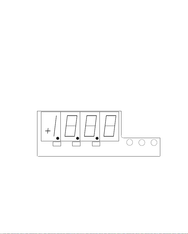
The unit is housed in a standard 1/8 DIN size case. For models
measuring Dc Volts, Ac Volts, Dc current and frequency, range is
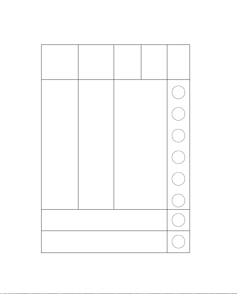
selectable by connecting the input to the proper screw terminal
located on the rear of the unit (see Chapter 2, page 6). For process,
high AC and high DC current meters, the range and proper display
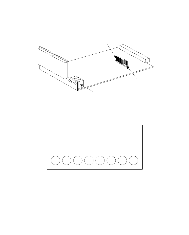
scaling are selected by jumper settings on the main board. Bright
red .56 inch high LED characters are easy to read. Instrument
power is derived from 115 Vac. Power input options include 24 or
220Vac. Engineering unit labels are supplied to indicate measured
units. The decimal point placement is configured by jumper
selection located behind the snap-off front lens.
DP1 DP3DP2
ZERO SCALESPAN
2
Page 4
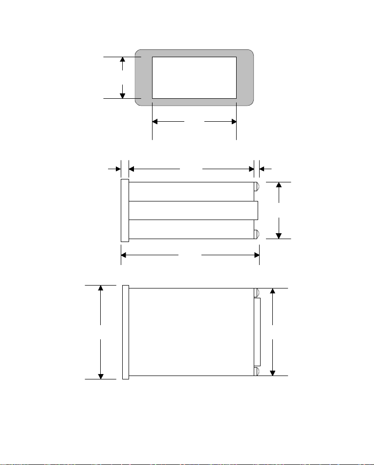
1.77"
(45mm)
PANEL CUT OUT
3.62"
(92mm)
.27"
(7mm)
3.78"
(96mm)
4.92"
(125mm)
5.59"
(142mm)
3
(18mm)
1.57"
(40mm)
3.54"
(90mm)
.71"
Page 5

Chapter 2 Setup
WARNING!
Dangerous voltages are present at the screw terminals. Always
remove power before working in this area for wiring,
disassembly, and all other activities that involve proximity to
electrical circuitry.
NOTE: The DP450-HACC, DP450-HDCC and DP450-E must be
configured to display the desired range. To access the main
board and its configuration jumpers, remove the front panel lens,
lift the display above and over the latch located at the bottom
front of the housing, and slide the assembly out of the case.
To begin making measurements, wire up the voltage, current, or
frequency-input wires plus AC line power to the instrument.
Because dangerous line voltage is present at the rear terminals
when power is applied, hook up the input signal wires first, then
the power. Plug in line power only after all connections are secure
to the rear screw terminals of the meter. Viewing the meter from
the rear, the screw terminals are numbered 1 through 8 from left to
right according to the drawing on page 6.
4
Page 6
TERMINAL
PROCESS
DC SHUNT
AC
TRANS-
CURRENT
FORMER
DC Current
AC Volts
DC Volts
Frequency
REAR
BLOCK
0-20mA
PROCESS
COMMON
0-5VDC
SHUNT
HIGH
SHUNT
COMMON
CT
HIGH
CT
COMMON
AC POWER
NEUTRAL
AC POWER
200mA
HOT
5
20mA
2A
COMMON
600V2mA
200V
20V
2V
200mV5A
1
2
3
4
5
6
7
8
Page 7
JP501
POSITION 10
SCALE POT
DP450-E ONLY
POSITION1
REAR VIEW
1 2 53 4 6 7 8
JP501
6
Page 8

DP450-VDC and DP450-VAC
AC or DC Voltmeters accept and display voltage ranges from
+/-199.9mV to +/-600Volts. The range is selected by connecting
the input to the proper screw terminal located at the rear of the
unit. See chart on page 5.
Range Table
RangeVDC Accuracy Resolution
0 to 199.9mV 0.5% 0.1mV
0 to 1.999V 0.5% 1mV
0 to 19.99V 0.5% 10.0mV
0 to 199.9V 0.5% 0.1V
0 to 600V 0.5% 1V
DP450-DCC DC Current
DC Ammeters accept and display current ranges from +/-1.999mA
to +/-5.00A. The range is selected by connecting the input to the
proper screw terminal located at the rear of the unit. See chart on
page 5 .
Range Table
Range ADC Accuracy Resolution
0 to ±1.999mA 0.5% 1uA
0 to ± 19.99mA 0.5% 10uA
0 to ± 199.9mA 0.5% 100uA
0 to ± 1.999A 0.5% 1mA
0 to ± 5.00 A 0.5% 10mA
7
Page 9

DP450-F
The Ac frequency meter is capable of measuring the frequency of
an Ac voltage of up to 1kHz throughout an input voltage range of
199.9mV to 600Vac. The voltage range of the frequency being
measured is selected by connecting the input to the proper screw
terminal located at the rear of the unit. See page 5.
Input Voltage Accuracy Resolution
199.9mV to 600VAC
0 to 1kHz 0.5% 1Hz
8
Page 10

DP450-HACC High AC Current
The DP450 HACC high Ac current meter accepts an input of
either 1 amp or 5 amp external current transformers and scales the
reading to the desired full scale reading of between 50.0 and 2000
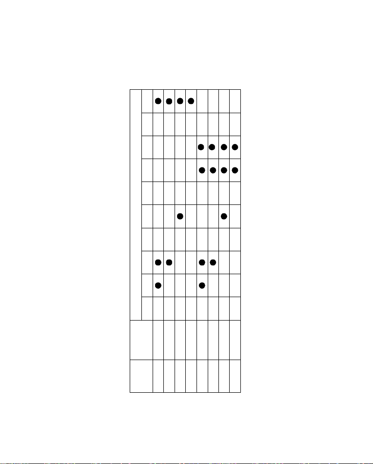
amps. Ranges are selected by a combination of jumpers located on
the main board (see page 6). No other adjustments are necessary.
The following ranges can be selected as full scale:
50 amps 1000 amps
100 amps 1500 amps
200 amps 2000 amps
500 amps
Use the table on the following page to configure the meter.
Example 1. Configure the meter to display 1500 amps Ac
full scale with a 5 amp input. Install jumpers provided on positions
5,7, and 8.
Example 2. Configure the meter to display 1000 amps Ac full
scale with a 1 amp input. Install jumpers provided on positions 3
and 10.
9
Page 11
AC HIGH CURRENT
10987654321
JUMPER CONNECTIONS
DISPLAY
50.0/500
100.0/1000
150.0/1500
199.9/1999
50.0/5005 AMP
100.0/1000
150.0/1500
199.9/1999
INPUT
1 AMP
1 AMP
10
1 AMP
1 AMP
5 AMP
5 AMP
5 AMP
Page 12

DP450-HDCC High Dc Current
The DP450 HDCC high Dc shunt meter accepts an input from 60,
100 and 150 Vdc current shunts and scales the reading to the
desired full scale reading of between 50.0 and 2000 amps. Ranges
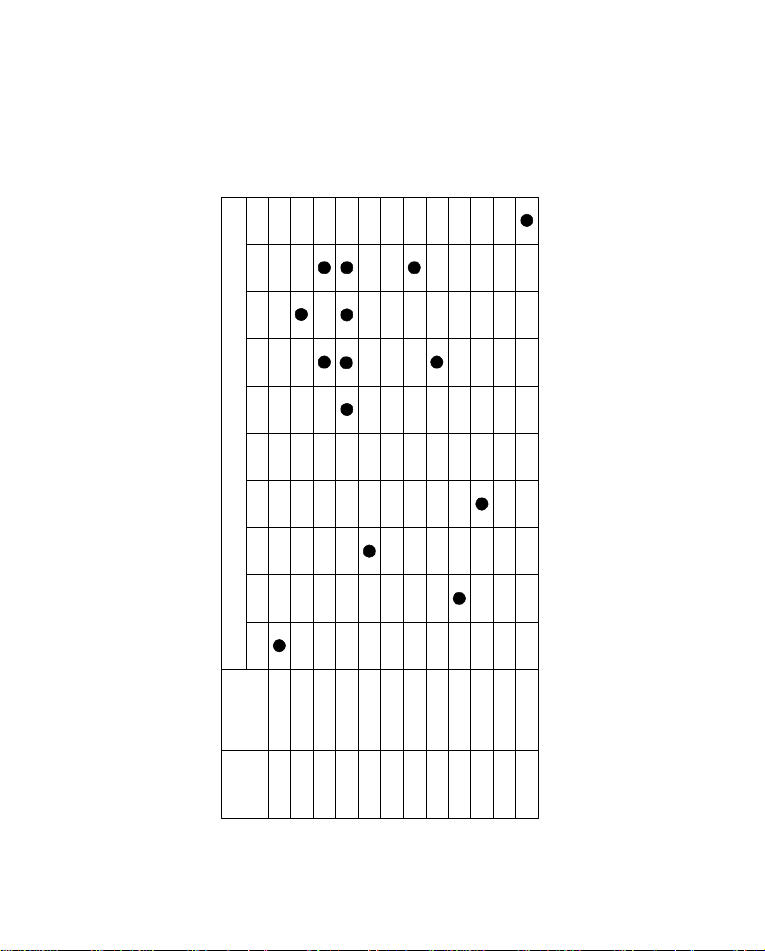
are selected by a combination of jumpers located on the main board
(see page 6). No other adjustments are necessary. Use the table on
the following page to configure the meter.
The following ranges can be selected as full scale:
50 amps 1000 amps
100 amps 1500 amps
200 amps 2000 amps
500 amps
Example 1. Configure the meter to display 500 amps Dc
full scale with a 100mVDc input. Install jumpers provided on
position 3.
Example 2. Configure the meter to display 1999 amps Dc full
scale with 60mVDc input. Install jumpers provided on positions
6,7,8 and 9.
11
Page 13
150.0/1500
199.9/1999
150mV
DC HIGH CURRENT
10987654321
JUMPER CONNECTIONS
DISPLAY
50.0/500
100.0/1000
150.0/1500
199.9/1999
50.0/500100mV
100.0/1000
150.0/1500
199.9/1999
50.0/500150mV
100.0/1000
INPUT
60mV
60mV
60mV
60mV
12
100mV
100mV
100mV
150mV
150mV
Page 14

DP450-E Process
The DP450-E Process meter accepts either voltage or current
inputs (0 to 5, 1 to 5 or 0 to 10 Vdc) or (0 to 20mA, 4 to 20mA).
Note: The unit is shipped from the factory calibrated to display 0
to 1000 counts with a 4 to 20mA input signal.
If the unit is to be used for 0 to 20mA, 0 or 1 to 5Vdc or 0 to
10Vdc it must be recalibrated according to the instructions in
Chapter 5. Voltage or current inputs are selected simply by wiring
the inputs to the proper rear terminals by installing removable
jumpers located on the main board and adjusting the scaling
potentiometer located behind the front panel lens (see figure, page
2). To place the decimal point in the desired location, place the
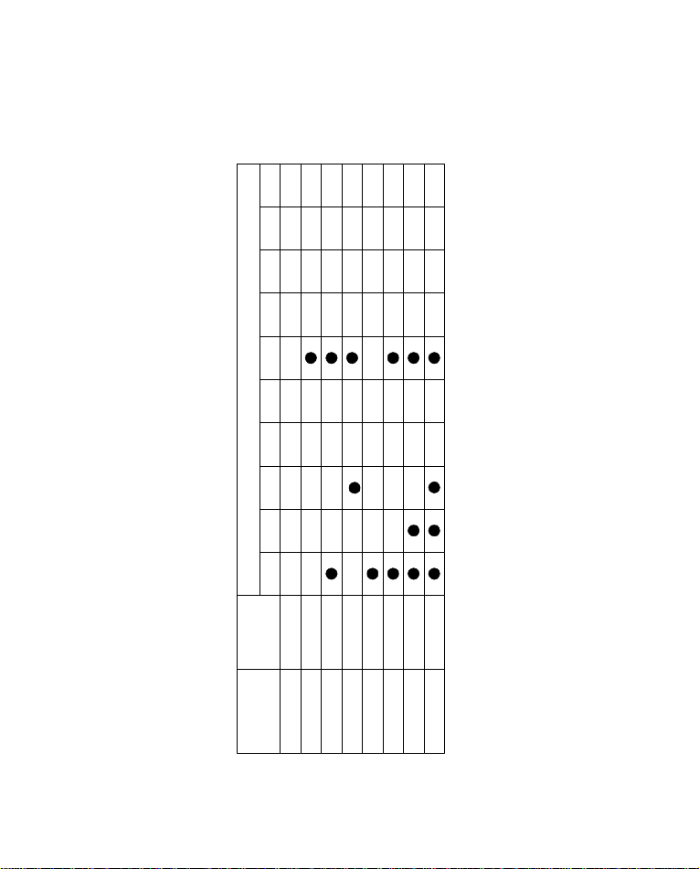
jumper provided below the main display. Use the table on the
following page to scale the meter.
Note: The table on the following page is based on 0 display counts
with 0 input. Offsets above zero (maximum 500 counts) will be
added to the full-scale range. It may be necessary to change
jumper settings to achieve the desired full-scale display range.
Range Table
Sensor Input Accuracy Resolution
0 to 20/4 to 20mA 0.5% 1count of 1999 counts
0 to 5/1 to 5Vdc 0.5%
0 to 10 Vdc 0.5%
Example: Scale the meter to display 200 counts with 4mA input
and 1500 counts with 20mA input.
1. Install a single jumper jack on position 6. Input 20.0 mA and
adjust the SCALE pot to 1500 counts.
2. Input 4.0 mA and adjust the ZERO pot to 200.
13
Page 15
3. Repeat steps 1 and 2 until no further adjustment is required.
Volts/Current*
Volts/Current*
Volts/Current*
Volts/Current*
*0 to 20 mA / 0 to 5 or 10 Vdc
PROCESS
10987654321
JUMPER CONNECTIONS
FULL
SCALE
0-100.0%
1070-1999
450-950
200-500
0-100.0%0-10 VDC
1000-1999
525-1000
INPUT
0-10 VDC
0-10 VDC
14
450-600
0-10 VDC
Page 16
Chapter 3 Alarm and Excitation Option
The alarm option enables the user to set a high and a low alarm
limit. When an alarm occurs, a red alarm LED indicator will turn
on and a normally open relay contact will close. The LED will turn
off and the relay will automatically reset when the alarm limit is no
longer exceeded. Two alarms are provided and are designated
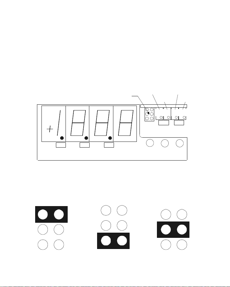
LOW and HIGH on the front panel. Alarm limits are set by
potentiometers located behind the front panel lens.
DP1 DP3DP2
SET HI/LO
JUMPER
COARSE
ADJ
ZERO SCALESPAN
FINE
ADJ
ALARM
LOW
LOW
COARSE
ADJ
ALARM
HIGH
HIGH
FINE
SET HI/LO JUMPER
SET LOW SET HIGH NORMAL
15
ADJ
Page 17

Setting the Alarm Limits
Note: Low alarm limits are set by the two coarse and
fine potentiometers on the left. High alarm limits are set
by the two coarse and fine potentiometers on the right.
STEP 1. Remove power from the instrument and disconnect the
signal input wires. Snap off the front panel lens. Apply power and
allow approximately 5 minutes of warm-up time.
STEP 2. Set the HI/LO jumper (located between the display
digits and the adjustment potentiometers) from the normal position
to either the SET HI or the SET LO position. See drawing, page
15.
STEP 3. Adjust the coarse potentiometer until the display reads
the value of the alarm limit. Make any final adjustments with the
fine adjust pot.
STEP 4. Return the HI/LO jumper to its normal position.
STEP 5. Install the front panel lens. Ensure that power is
disconnected before reconnecting signal wires.
16
Page 18
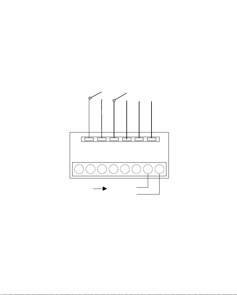
Alarm and Excitation Option Wiring
Blade terminals accessible at the back of the instrument provide
connections to the alarm option. Female connectors are supplied to
wire the alarm option into your system. Excitation power supply is
standard with the dual alarm.
ALM2(HIGH)
N.O. RELAY
CONTACT
ALM1(LOW)
N.O. RELAY
CONTACT
TRANSDUCER
EXCITATION
-
REAR VIEW
1 2 53 4 6 7 8
INPUT
POWER
NEUTRAL
HOT
+
17
Page 19

Chapter 4 General Specifications
Stability with Temperature:
±100ppm/°C maximum
Noise Rejection:
NMRR: <40dB, 50/60 Hz
CMRR: <130dB w/ 250Ω unbalance typical
Display:
3 1/2 digit, 7-segment red/orange LED, 0.56" (14.2mm) height
Environmental:
0°C to 50°, <85% RH, non-condensing
Case Construction:
One-piece black ABS plastic
Size:
Case: 1/8 DIN 1.57" X 3.54"X 4.56"(4.0cm X 9.0cm X 10.9cm)
Bezel: 1.89” X 3.78” (4.8cm X 9.6cm)
Panel Cutout: 1.77" X 3.62" (4.5cm X 9.2cm)
Weight:
1lb. (454g)
Power:
115Vac +/- 10%, 50 or 60 Hz
220Vac +/- 10%, 50 or 60 Hz
24Vac +/- 10%, 50 or 60 Hz
Excitation Power Supply
+10 Vdc @ 30mA
18
Page 20

Chapter 5 Calibration
DP450-VDC DC Volts
Equipment Required:
1. Precision DC voltage source with a resolution to 0.1mV and
an accuracy of ±0.1%
2. Interconnecting copper wire from the DC source to the
indicator.
3. Trimmer adjusting tool.
STEP 1. Disconnect power from the unit and use copper
connecting leads, connect the output of the DC voltage source to
terminals 5 (+) and 6 (-) of the indicator according to the chart on
page 5.
STEP 2. Remove the front panel lens, reconnect power and allow
for a 5-minute warm-up.
STEP 3. Input 0.0 mV from the DC voltage source and adjust the
ZERO pot for a display of 0.0±1 count. (Refer to the figure on page
15 for the location of the zero and span pots).
STEP 4. Input 190.0 mV from the DC voltage source and adjust
the SPAN pot for a reading of 190.0±1 count.
STEP 5. Repeat steps 3 and 4 until no further adjustment is
needed.
19
Page 21

DP450-VAC AC Volts
Equipment Required:
1. Precision AC voltage source with a resolution to 0.1mV and
an accuracy of ±0.1%
2. Interconnecting copper wire from the AC source to the
indicator.
3. Trimmer adjusting tool.
STEP 1. Disconnect power from the unit and using copper
connecting leads, connect the output of the AC Voltage source to
terminals 5 and 6 of the indicator according to the chart on page 5.
STEP 2. Remove the front panel lens and reconnect power and
allow for a 5-minute warm-up.
STEP 3. Input 0.0 mV from the AC voltage source and adjust the
ZERO pot for a display of 0.0±1 count. (Refer to the figure on page
15 for the location of the zero and span pots).
STEP 4. Input 190.0 mV at the measured frequency from the AC
source and adjust the SPAN pot for a reading of 190.0±1 count.
STEP 5. Repeat steps 3 and 4 until no further adjustment is
needed.
20
Page 22

DP450-F Frequency
Equipment Required:
1. Precision AC voltage source with a resolution to 0.1mV and
an accuracy of ±0.1%
2. Interconnecting copper wire from the AC source to the
indicator.
3. Trimmer adjusting tool.
STEP 1. Disconnect power from the unit and using copper
connecting leads, connect the output of the AC Voltage source to
terminals 5 and 6 of the indicator according to the chart on page 5.
STEP 2. Remove the front panel lens and reconnect power and
allow for a 5-minute warm-up.
STEP 3. Input 100.0 mV at 60 Hz from the AC voltage source
and adjust the ZERO pot for a display reading of 60±1count.
STEP 4. Input 100.0 mV @400 Hz from the AC voltage source
and adjust the SPAN pot for a display reading of 400±1count.
STEP 5. Repeat steps 2 and 3 until no further adjustment is
needed.
21
Page 23

DP450-DCC DC Current
Equipment Required:
1. Precision DC current source with a resolution to 0.1mA and
an accuracy of ±0.1%
2. Interconnecting copper wire from the DC current source to the
indicator.
3. Trimmer adjusting tool.
STEP 1. Disconnect power from the unit and use copper
connecting leads, connect the output of the DC current source to
terminals 3 (+) and 6 (-) of the indicator according to the chart on
page 5.
STEP 2. Remove the front panel lens, reconnect power and allow
for a 5-minute warm-up.
STEP 3. Input 0.0 mA from the DC current source and adjust the
ZERO pot for a display of 0.0±1 count. (Refer to the figure on page
15 for the location of the zero and span pots).
STEP 4. Input 190.0 mA from the DC current source and adjust
the SPAN pot for a reading of 190.0±1 count.
STEP 5. Repeat steps 3 and 4 until no further adjustment is
needed.
22
Page 24

DP450-E Process Meter
The DP450-E can be custom scaled to display a full-scale reading
from 200 to 1999 counts by installing removable jumpers located
on the main board and adjusting the scaling potentiometer located
behind the front panel lens.
4-20mA
Equipment Required:
1. Precision DC current source with a resolution of 0.1mA DC
and an accuracy of 0.1%.
2. Interconnecting copper wire from the DC current source to the
indicator.
3. Trimmer adjusting tool.
STEP 1. Disconnect power from the unit and remove the front
panel lens.
STEP 2. Connect the DC current source to terminal 1 (+) and
terminal 2 (-) located on the rear of the unit. Reconnect power and
turn the unit on. Allow for a 5-minute warm-up.
STEP 3. Input 4.0mA from the DC current source and adjust the
ZERO pot for a display reading of 0.0 ± 1 count.
STEP 4. Input 20.0 mA from the DC current voltage source and
adjust the SPAN pot for a reading of 100.0±1 count.
STEP 5. Repeat steps 3 and 4 until no further adjustment is
needed.
23
Page 25

0 to 20mA
Equipment Required:
1. Precision DC current source with a resolution of 0.1mA DC
and an accuracy of 0.1%.
2. Interconnecting copper wire from the DC current source to the
indicator.
3. Trimmer adjusting tool.
STEP 1. Disconnect power from the unit and remove the front
panel lens.
STEP 2. Connect the DC current source to terminal 1 (+) and
terminal 2 (-) located on the rear of the unit. Reconnect power and
turn the unit on. Allow for a 5-minute warm-up.
STEP 3. Input 0.0mA from the DC current source and adjust the
ZERO pot for a display reading of 0.0 ± 1 count.
STEP 4. Input 20.0 mA from the DC current source and adjust
the SPAN pot for a reading of 100.0±1 count.
STEP 5. Repeat steps 3 and 4 until no further adjustment is
needed.
24
Page 26

1 to 5VDC
Equipment Required:
1. Precision DC voltage source with a resolution of 0.1mV DC
and an accuracy of 0.1%.
2. Interconnecting copper wire from the DC voltage source to the
indicator.
3. Trimmer adjusting tool.
STEP 1. Disconnect power from the unit and remove the front
panel lens.
STEP 2. Connect the DC voltage source to terminal 3 (+) and
terminal 2 (-) located on the rear of the unit. Reconnect power and
turn the unit on. Allow for a 5-minute warm-up.
STEP 3. Input 1.0VDC from the DC voltage source and adjust
the ZERO pot for a display reading of 0.0 ± 1 count.
STEP 4. Input 5.0VDC from the DC voltage source and adjust
the SPAN pot for a reading of 100.0±1 count.
STEP 5. Repeat steps 3 and 4 until no further adjustment is
needed.
25
Page 27

0 to 5VDC and 0 to 10VDC
Equipment Required:
1. Precision DC voltage source with a resolution of 0.1mV DC
and an accuracy of 0.1%.
2. Interconnecting copper wire from the DC voltage source to the
indicator.
3. Trimmer adjusting tool.
STEP 1. Disconnect power from the unit and remove the front
panel lens.
STEP 2. Connect the DC voltage source to terminal 3 (+) and
terminal 2 (-) located on the rear of the unit. Reconnect power and
turn the unit on. Allow for a 5-minute warm-up.
STEP 3. Input 0.0VDC from the DC voltage source and adjust
the Zero pot for a display reading of 0.0 ± 1 count.
STEP 4. Input 5.0VDC from the DC voltage source and adjust
the Span pot for a reading of 100.0±1 count.
STEP 5. Repeat steps 3 and 4 until no further adjustment is
needed.
26
Page 28

DP450-HACC High AC Current
Equipment Required:
1. Precision AC current source with a resolution of 0.1mA AC
and an accuracy of 0.1%.
2. Interconnecting copper wire from the AC voltage source to the
indicator.
3. Trimmer adjusting tool.
STEP 1. Disconnect power from the unit and remove the front
panel lens. Carefully remove the electronics from the housing by
lifting the display above and over the latch located at the bottom
front of the housing and slide the assembly out of the case.
STEP 2. Make note of the jumper settings on JP501. Carefully
remove them and replace jumpers on position 3 and position 10.
STEP 3. Connect the AC current source to terminals 5 and 6
located on the rear of the unit. Reconnect power and turn the unit
on. Allow for a 5-minute warm-up.
STEP 4. Input 0.0 amp from the AC current source and adjust
the ZERO pot for a display reading of 0 counts ±1 count.
STEP 5. Input 1 amp @ 60 Hz from the AC current source and
adjust the SPAN pot for a display reading of 1000 counts ±1 count.
STEP 6. Remove the jumper on positions 3 and 10 and replace
all of the jumpers to their original settings.
27
Page 29

DP450-HDCC High DC Current
Equipment Required:
1. Precision DC current source with a resolution of 0.1mV DC
and an accuracy of 0.1%.
2. Interconnecting copper wire from the DC current source to the
indicator.
3. Trimmer adjusting tool.
STEP 1. Disconnect power and current from the unit and remove
the front panel lens. Remove the electronics from the housing by
lifting the display above and over the latch located at the bottom
front of the housing and slide the assembly out of the case.
STEP 2. Make note of the jumper settings on JP501. Carefully
remove them and replace one jumper on position 7.
STEP 3. Connect the DC voltage source to terminals 4 (+) and
5(-) located on the rear of the unit. Reconnect power and turn the
unit on. Allow for a 5-minute warm-up.
STEP 4. Input 0.0mV from the DC voltage source and adjust the
ZERO pot for a display reading of 0-counts±1 count.
STEP 5. Input 90.0mV from the DC voltage source and adjust
the SPAN pot for a display reading of 1800 counts±1 count.
STEP 6. Remove the jumper on position 7 and replace all of the
jumpers to their original settings. Calibration is complete.
28
 Loading...