

Page 1
®
®
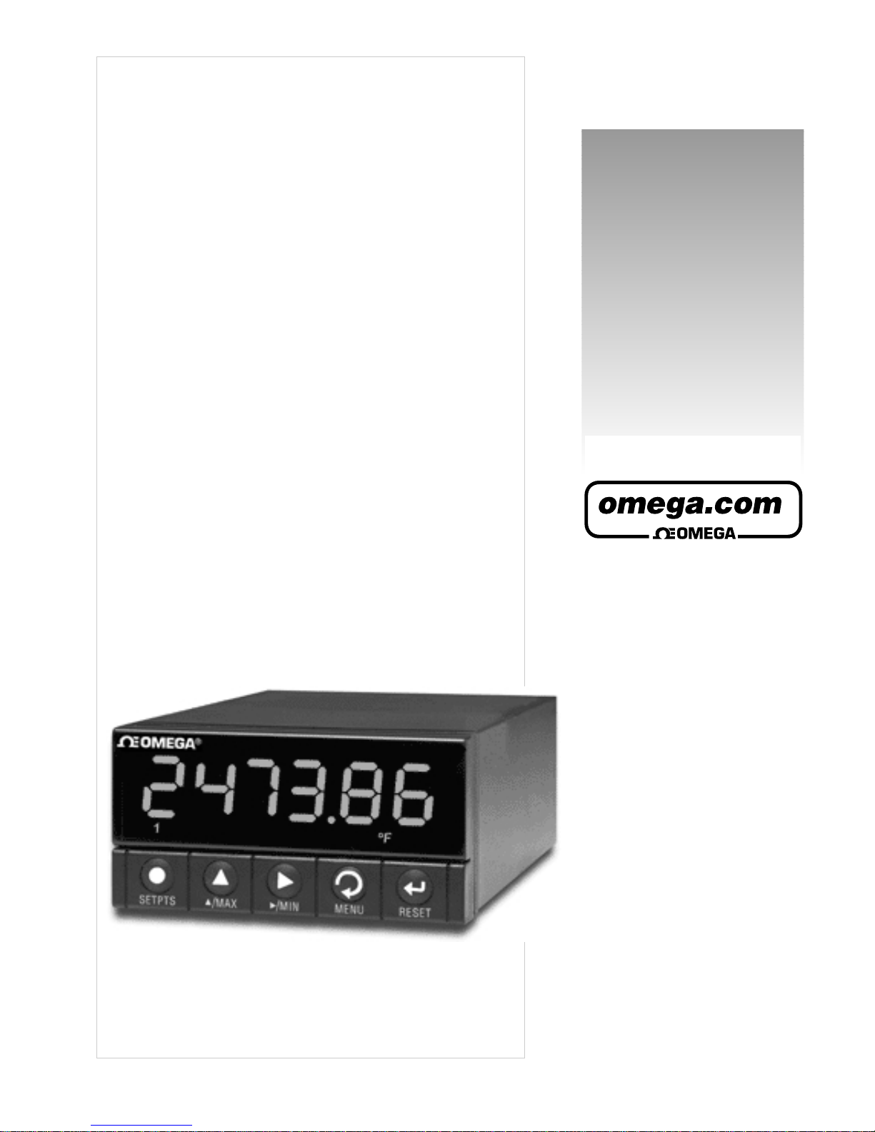
User’s Guide
DP41-B Series
Serial Communication Optio
n
Shop on line at
RoHS 2 Compliant
Page 2

It is the policy of OMEGA to comply with all worldwide safety and EMC/EMI regulations that apply.
OMEGA is constantly pursuing certification of its products to the European New Approach Directives. OMEGA will add
the mark to every appropriate device upon certification.
The information contained in this document is believed to be correct but OMEGA Engineering, Inc. accepts no liability for any errors it contains,
and reserves the right to alter specifications without notice.
WARNING: These products are not des
igned for use in, and should not be used for, patient connected applications.
This device is marked with the international hazard symbol. It is important to read the Setup Guide before installing or commissioning this
device as it contains important information relating to safety and EMC.
Servicing North America:
USA: One Omega Drive, P.O. Box 4047
ISO 9001 Certified Stamford CT 06907-0047
TEL: (203) 359-1660 FAX: (203) 359-7700
e-mail: [email protected]
Canada:
976 Bergar
Laval (Quebec) H7L 5A1
TEL: (514) 856-6928 FAX: (514) 856-6886
e-mail: [email protected]
For immediate technical or application assistance:
USA and Canada: Sales Service: 1-800-826-6342 / 1-800-TC-OMEGA
®
Customer Service: 1-800-622-2378 / 1-800-622-BEST
®
Engineering Service: 1-800-872-9436 / 1-800-USA-WHEN
®
Mexico and TEL: (001)800-TC-OMEGA® FAX: (001) 203-359-7807
Latin America: En Español: (001) 203-359-7803
e-mail: [email protected]
Servicing Europe:
Benelux: Postbus 8034, 1180 LA Amstelveen, The Netherlands
TEL: +31 20 3472121 FAX: +31 20 6434643
Toll Free in Benelux: 0800 0993344
e-mail: [email protected]
Czech Republic:
Frystatska 184, 733 01 Karviná
TEL: +420 59 6311899 FAX: +420 59 6311114
e-mail: [email protected]
France:
11, rue Jacques Cartier, 78280 Guyancourt
TEL: +33 1 61 37 29 00 FAX: +33 1 30 57 54 27
Toll Free in France: 0800 466 342
e-mail: [email protected]
Germany/Austria: Daimlerstrasse 26, D-75392 Deckenpfronn, Germany
TEL: +49 7056 9398-0 FAX: +49 7056 9398-29
Toll Free in Germany: 0800 639 7678
e-mail: [email protected]
United Kingdom:
One Omega Drive
ISO 9002 Certified River Bend Technology Centre
Northbank, Irlam Manchester M44 5BD United Kingdom
TEL: +44 161 777 6611 FAX: +44 161 777 6622
Toll Free in England: 0800 488 488
e-mail: [email protected]
OMEGAnet® On-Line Service
www.omega.com
Internet e-mail
®
®
Page 3

i
Table of Contents
SECTION 1 INTRODUCTION ....................................................................................1-1
SECTION 2 HARDWARE ..........................................................................................2-1
2.1 Definition of terms......................................................................................2-1
2.2 RS-232 and RS-485 hardware ..................................................................2-1
SECTION 3 USING THE CONFIGURATION SETUP................................................3-1
SECTION 4 DEFINITIONS.........................................................................................4-1
4.1 Meter or DCE.............................................................................................4-1
4.2 Computer or DTE ......................................................................................4-1
4.3 Point to Point .............................................................................................4-1
4.4 Multi Point (Multi-Drop)..............................................................................4-1
4.5 Simplex......................................................................................................4-1
4.6 Half Duplex................................................................................................4-1
4.7 Full Duplex.................................................................................................4-1
4.8 RS-232 (CCITT V.24) ................................................................................4-2
4.9 RTS .......................................................................................................4-2
4.10 RS-422 ......................................................................................................4-2
4.11 RS-485 ......................................................................................................4-2
4.12 ASCII .......................................................................................................4-3
4.13 Hex ASCII..................................................................................................4-4
4.14 Transmission Voltage Levels.....................................................................4-6
4.15 Recognition Character...............................................................................4-6
4.16 RAM .......................................................................................................4-6
4.17 EEPROM ...................................................................................................4-6
SECTION 5 BAUD RATES ........................................................................................5-1
SECTION 6 CHARACTER WAVEFORM ...................................................................5-1
SECTION 7 CLASSES OF OPERATION ..................................................................7-1
7.1 Point to Point .............................................................................................7-1
7.1.1 Continuous Mode ........................................................................7-1
7.1.1.1 Message Handshake ..................................................................7-2
7.1.1.2 Character Handshake .................................................................7-2
7.1.2 Command Mode..........................................................................7-2
7.2 Multi Point..................................................................................................7-2
7.2.1 Command Mode..........................................................................7-2
7.2.2 Alarm Mode.................................................................................7-3
7.3 The Meter as a Remote Display................................................................7-4
7.4 The Meter as a Double Tasking Remote Meter .........................................7-4
7.4.1 Command Structure for Double Tasking .....................................7-5
Page 4

ii
SECTION 8
COMMAND AND RESPONSE STRUCTURE
..........................................8-1
8.1 Message String..........................................................................................8-1
8.1.1 “Data” and “Non Data”...................................................................8-1
8.1.2 Brackets and Spaces .....................................................................8-1
8.2 Commands and Structure..........................................................................8-2
8.2.1 Read Communications Configuration Command ...........................8-2
8.2.2 General Command Structure .........................................................8-3
8.2.3 Command Formats.........................................................................8-4
8.2.4 Command Suffix.............................................................................8-6
8.3 Response Structure...................................................................................8-9
8.3.1 No Error..........................................................................................8-9
8.3.2 Echo Mode .....................................................................................8-9
8.3.3 No Echo Mode................................................................................8-9
8.4
Data Length Corresponding to the Response Structure
..........................8-10
8.5 Error Response........................................................................................8-11
8.5.1 Error Response Format ................................................................8-11
8.5.2 Error Message ..............................................................................8-11
8.5.3 Description ...................................................................................8-12
8.6 Status Character Formats .......................................................................8-13
8.6.1 Alarm Status Characters ..............................................................8-13
8.6.2 Peak/Valley (HI/LO) Status Characters ........................................8-14
8.7 "VO1" Response Data Format.................................................................8-15
8.8 “^AE” Response Format ..........................................................................8-16
8.9
Examples
.................................................................................................8-16
SECTION 9 METER BUS RESPONSE .....................................................................9-1
9.1 Point to Point or Multi Point Command Mode............................................9-1
9.1.1 Meter’s Response Time..................................................................9-2
9.2 Point to Point Continuous Mode................................................................9-3
9.2.1 Meter’s Response Time..................................................................9-3
9.2.2 Communicating with the Meter when in Continuous Mode ............9-3
9.3 Multi Point Alarm Mode Response ............................................................9-4
9.4 Watchdog timer for communication...........................................................9-4
SECTION
10 DATA FORMAT COMMANDS (P, G, R, W)
..........................................10-1
10.1 Reading Configuration (“RdG.CNF”) .......................................................10-2
10.2 Input Configuration (“INP.CNF” and “INPUt”) ..........................................10-3
10.3 Setting Count By (“CNtby”) and Decimal Point (“SEt dP”).......................10-4
10.4
Filter
Configuration
“FILtER” and “
OUt.tyP”)............................................10-5
10.5 Setpoint 1 and 2 Configuration (“SP.CNF”) .............................................10-6
10.6 Alarm (Setpoints 3 and 4) Configuration (“AL.CNF”)...............................10-7
10.7 Alarm Functions (“AL.CNF and AL.MOdE”).............................................10-8
10.8 Alarm Delay: (“NUM.dLy”) .......................................................................10-8
10.9 Output Configuration
(“OUt.CNF”) and A to D Rate (“Ad.RAtE”)
................10-9
10.10 Input Type (“INPUt”) and Reading Scale & Offset (“Rd.SC.OF”)...........10-10
10.11 Serial Communications Configuration (“COMM”) ..................................10-11
10.12 Data Format (“dAt.FMt”) ........................................................................10-12
10.13 Communications Bus Format (“bUS.FMt”) ............................................10-13
10.14 Lockout Configuration (“LCk.CNF”) .......................................................10-14
10.15 Lockout Configuration (“LCk.CNF”) and Normal Color (“N.COLOR”)....10-15
10.16 Color Configuration (“COLOR”) .............................................................10-16
Table of Contents
Page 5

iii
Table of Contents
10.17 Block A...................................................................................................10-17
10.18 Block B ..................................................................................................10-19
10.19 Block C ..................................................................................................10-21
10.20 Block D ..................................................................................................10-22
10.21 R/W44 (Block E) ....................................................................................10-23
10.22 R/W45 (Block F) ....................................................................................10-23
10.23 R46 ...................................................................................................10-23
10.24 R47 ...................................................................................................10-23
10.25 R48 ...................................................................................................10-23
10.26 R/W50 ...................................................................................................10-24
10.27 R/W51,R/W52,R/W53,R/W54,R/W55,R/W56,R/W57,R/W58 R/W59 R/W5A....10-25
10.28 Set Sign and Decimal Point Format ......................................................10-26
10.29 RS-485 Meter “AddRES” .......................................................................10-27
10.30 Number of Readings between each Transmission (“SER CNt”)............10-27
10.31 Recognition Character (SER.RCG) .......................................................10-28
10.32 Units of Measure (SER.UOM) ...............................................................10-28
10.33 TX/RX Turnaround Delay (Serial Delay SER.dLy) ................................10-29
10.34 Reading, Input, or Output Scale Factor (“RdG SC”, “INP SC”, “OUt SC”)....10-29
10.35 Reading Offset(“RdG OF”), Input Offset(“INP OF”), or Output Offset(“OUt OF”)..10-31
10.36 Setpoint 1 and 2 Hysteresis (“SP db”) .................................................10-32
10.37 Alarm (SP 3 and SP 4) Hysteresis (“AL db”) .........................................10-32
MODBUS SUPPLEMENT .....................................................................................M-1
Figure 2-1 RS-232 / RS-485 Option Board.............................................................2-1
Figure 2-2 Main Board with the RS-232/RS-485 Option Board ..............................2-3
Figure 2-3 Rear of Meter with J4 connection ..........................................................2-3
Figure 2-4A RJ-11 to D9 Connector..........................................................................2-4
Figure 2-4B RJ-11 to D25 Connector........................................................................2-4
Figure 2-5 Multipoint, Half-Duplex RS-485 Connection ..........................................2-5
Figure 2-6 Multipoint Full-Duplex RS-485 Connection ...........................................2-6
Figure 6-1 Character Waveform .............................................................................5-1
Page 6

iv
Table 2.1 Meter Hookup (RS-232) to the Computer .............................................2-4
Table 2.2 Meter Hookup (RS-232) to the Printer...................................................2-4
Table 2.3 Half-Duplex Hookup (RS-485) to the Computer....................................2-5
Table 2.4 Full-Duplex Hookup to the Computer ....................................................2-6
Table 4.1 The ASCII Character Code....................................................................4-5
Table 4.2 Meter Receiving Voltages......................................................................4-6
Table 4.3 Meter Transmitting Voltages ..................................................................4-6
Table 8.1 Command Prefix Letters (Command Classes)......................................8-3
Table 8.2 Command Letters and Suffixes .............................................................8-6
Table 8.3 Error Messages ...................................................................................8-11
Table 8.4 Alarm Status Characters .....................................................................8-13
Table 8.5 Peak/Valley Status Characters............................................................8-14
Table 8.6 Special Characters ..............................................................................8-15
Table 9.1 Reading Rate for Command Mode........................................................9-2
Table 9.2 Reading Rate for Communication ........................................................9-3
Table 10.1 Reading Configuration.........................................................................10-2
Table 10.2 Input Configuration .............................................................................10-3
Table 10.3 Count By and Decimal Point ...............................................................10-4
Table 10.4 Filter Configuration and Output Type .................................................10-5
Table 10.5 Setpoint Configuration.........................................................................10-6
Table 10.6 Alarm Configuration ............................................................................10-7
Table 10.7 Alarm Configuration and Mode ...........................................................10-8
Table 10.8 Alarm Delay.........................................................................................10-8
Table 10.9 Output Configuration ..........................................................................10-9
Table 10.10 Input Type and Reading Scale and Offset.........................................10-10
Table 10.11 Serial Communications Configuration ...............................................10-11
Table 10.12 Data Format .....................................................................................10-12
Table 10.13 Bus Format........................................................................................10-13
Table 10.14 Lockout Configuration ......................................................................10-14
Table 10.15 Lockout Configuration and Normal Color ..........................................10-15
Table 10.16 Color Configuration ..........................................................................10-16
Table 10.17 R/W40 (Block A) ...............................................................................10-17
Table 10.18 R/W41 (Block B)................................................................................10-19
Table 10.19 R/W42 (Block C) ...............................................................................10-21
Table 10.20 R/W43 (Block D)................................................................................10-22
Table 10.21 R/W44 (Block E)................................................................................10-23
Table 10.22 R/W45 (Block F) ...............................................................................10-23
Table 10.23 R/W50 ...............................................................................................10-24
Table 10.24 R/W50 NUM.PNt and MENU selection ............................................10-24
Table 10.25 R/W5XXXXX .....................................................................................10-25
Table 10.26 Setpoint Values ................................................................................10-26
Table 10.27 Serial Delay (“SER.dLy”) ..................................................................10-29
Table 10.28 Reading Scale(“RdG SC”),Input Scale(“INP SC”),Output Scale(“OUt SC”)....10-30
Table 10.29 Reading Offset(“RdG OF”),Input Offset(“INP OF”),Output Offset(“OUt OF”) ..10-31
Table of Contents
Page 7
1-1
1. Introduction
This manual is intended to facilitate digital communication between your computer (or
other controlling device) and one or more meters.
This digital-communications manual is provided for use with the meters’ OWNER’S
MANUAL, which provide details of all applicable inputs, connections, options,
pushbutton controls and programming procedures.
Information that is especially important to note is identified by these labels:
• NOTE
• WARNING
• CAUTION
• IMPORTANT
NOTE: provides you with information that is important to successfully setup
and use the Programmable Digital Meter.
CAUTION or WARNING: tells you about the risk of electric shock.
CAUTION, WARNING or IMPORTANT: tells you of circumstances or
practices that can effect the meter's functionality and must refer to
accompanying documents.
Customer Service
If you need assistance, please call the nearest Customer Service Department, listed in
this manual.
Manuals, Software
The latest Operation and Communication Manual as well as free configuration
software and ActiveX controls are available from the website listed in this manual or
on the CD-ROM enclosed with your shipment.
Communication Menu
The Communication menu only appears with devices purchased with the RS-232C /
RS-485 Serial Communications Option. Purchasing the controller with Serial
Communications permits a controller to be connected directly to the PC’s available
COM port. Device can be configured or monitored from an IBM PC compatible
computer using software available on our CD or on our website.
Page 8

2-1
2. Hardware
2.1 DEFINITION OF TERMS
RX: Received line on RS-232
TX: Transmit line on RS-232
RTS: Request to send
+RX: First pair received line on RS-422/485
+TX: First pair transmit line on RS-422/485
-RX: Second pair received line on RS-422/485
-TX: Second pair transmit line on RS-422/485
RTN: Ground/Return
2.2 RS-232 AND RS-485 HARDWARE
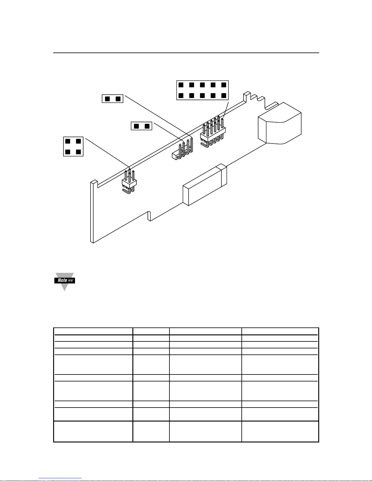
INSTALLATION: The RS-232/485 card is approximately 1" high and 5" long. It is
installed with the meter removed from its case (Refer to Section 5 of your meter’s
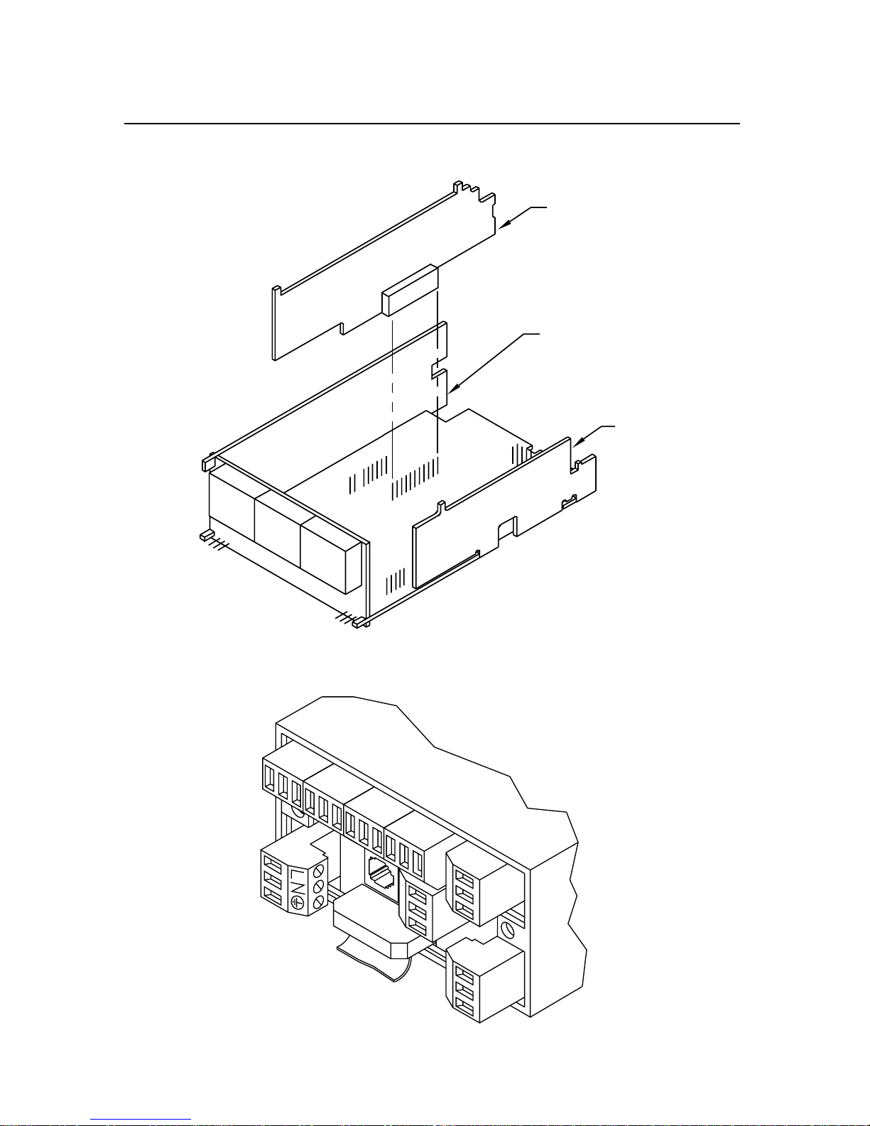
Owner’s Guide for instructions on how to open the meter). P11 inserts into J11 of the
main board located next to the transformer (Refer to Figure 2-2). The board is held in
position by a plastic guide on the rear of the display board and plastic assembly at the
rear of the meter. The 6-pin telephone jack, J4, is available at the rear of the meter
case, and accepts a type RJ-11 or RJ-12 telephone plug (Refer to Figure 2-3).
Logic signals are opto-isolated, and drive power is obtained from a galvanically-isolated
transformer winding so that the ±7 V signal levels from the meter can be slaved to the
external controller (computer) ground; earthing that ground is recommended.
Page 9
2-2
2. Hardware
ABCDE
S
1
S1
A
B
S
3
P
11
S3
11
1
1A
J4
1
6
S
2
S2
A
S
4
S4
A
Figure 2-1. RS-232 / RS-485 Option Board
You should install the option board in such a way the pin “1A” of “P11” is
aligned with pin “1A” of “J11” (on main board, refer to Figure 2-2).
When interfacing the meter to devices that do not have handshaking lines, i.e.
RTS/CTS, the S3-E Jumper should be installed. However, when interfacing to a PC,
the S3-E should be removed.
JUMPER RS232 RS485 HALF DUPLEX RS485 FULL DUPLEX
S1-A CLOSE OPEN OPEN
S1-B OPEN CLOSE OPEN
S2-A OPEN CLOSE CLOSE
S3-A
(CLOSE FOR TERMINAL OPEN * *
RESISTOR)
S3-B OPEN CLOSE OPEN
S3-C
(CLOSE FOR TERMINAL OPEN * *
RESISTOR)
S3-D OPEN CLOSE OPEN
S3-E * OPEN OPEN
(CLOSE FOR RTS TRUE)
S4
(CLOSE FOR OPEN * *
CONTINUOUS MODE)
Note: * means optional, select as required.
Page 10
2-3
2. Hardware
Figure 2-2. Main Board with the RS-232/RS-485 Option Board
Figure 2-3. Rear of Meter with J4 connection.
RS232/RS485 BD
SIGNAL INPUT BD
POWER BD
P11
J10
J11
11
1A
1A
11
P6
P7
P18A
P18B
P9
P3
J4
P1
P2
P5
Page 11
2-4
2. Hardware
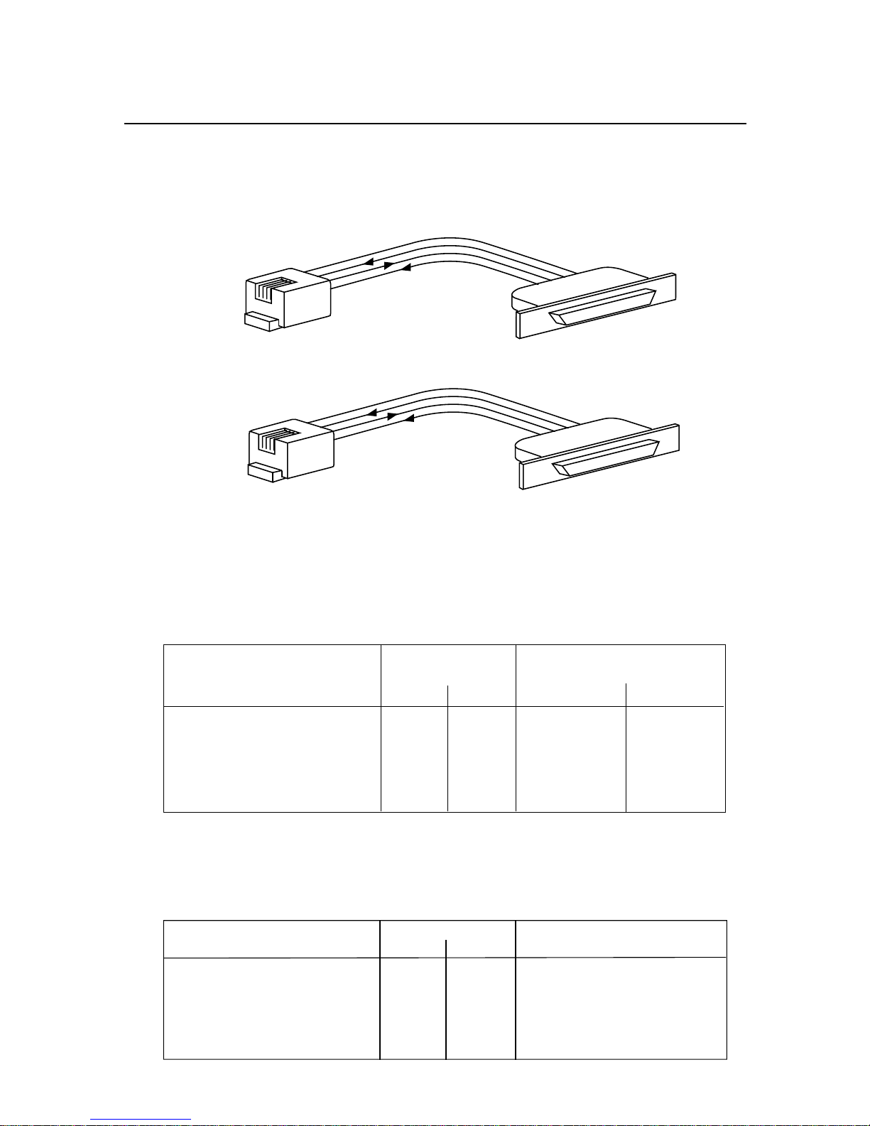
Figures 2-4A and Figure 2-4B show the four-wire RS-232 connections between the
host computer/controller using either a 9-pin or 25-pin “D” connector and the meter
(point-to-point full duplex, with RTS handshake).
Figure 2-4A. RJ-11 to D9 Connector
Figure 2-4B. RJ-11 to D25 Connector
Table 2.1 shows the pin connection assignments between the RS-232 connection on
the meter and the 9-pin or 25-pin “D” connectors of your computer.
Table 2.1. Meter Hookup (RS-232) to the Computer
METER COMPUTER
(DCE) (DTE)
PIN SIGNAL/FUNCTION RJ-11 RJ-12 D9 D25
RTS, meter from computer 1 2 7 4
TX, meter = RX, computer 2 3 2 3
RX, meter = TX, computer 3 4 3 2
Return 4 5 5 7
NC (not connected) 1,6 (all others)
Table 2.2 shows the pin connection assignments between the RS-232 connection on
the meter and the 9-pin or 25-pin “D” connectors of your printer.
Table 2.2. Meter Hookup (RS-232) to the Printer
METER PRINTER
PIN SIGNAL/FUNCTION RJ-11 RJ-12 FUNCTIONS
RTS, meter 1 2 Data Terminal Ready (DTR)
TX, meter 2 3 Received Data (RXD)
RX, meter 3 4 Not Connected
Return 4 5 Signal Return
NC (not connected) 1,6
3
5
7
2
4
3
2
1
RJ-11
D9
2
7
4
3
4
3
2
1
RJ-11
D25
Page 12
2-5
2. Hardware
Logic symbols are opto-isolated, and drive power is obtained from a galvanically-
isolated transformer winding so that the differential signals (minimum ±2 V) will not be
altered by an external ground; earthing of the external transceiver power supply is
recommended to limit common-mode voltage.
The RS-485 hardware may be operated point-to-point (e.g., as RS-422 equipment),
OR
in multipoint, sharing the bus wires with up to 32 other meters.
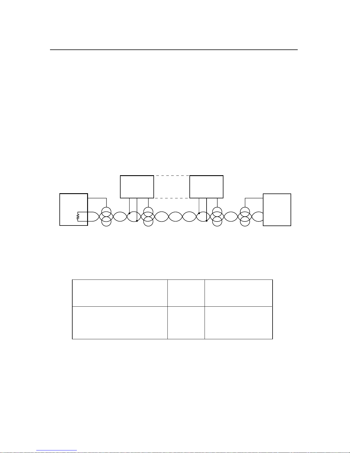
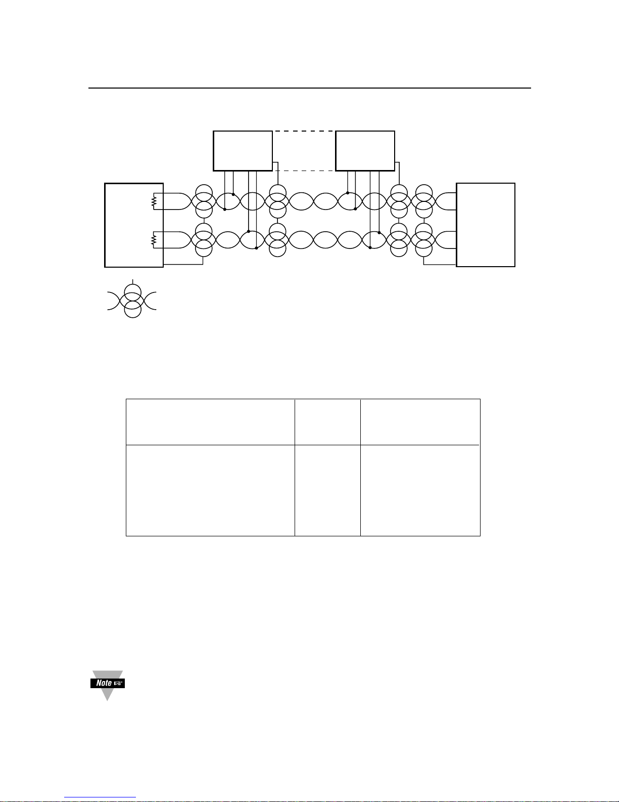
The RS-485 cabling may be a single pair of wires (usually with a shield) for HALF
DUPLEX (Figure 2-5), or two such pairs for FULL DUPLEX (Figure 2-6). The
configurations shown are for bus operation, with tap-offs for each meter.
Figure 2-5. Multipoint, Half-Duplex RS-485 Connection
Table 2.3. Half-Duplex Hookup (RS-485) to the Computer
METER COMPUTER
(DCE) (DTE)
PIN SIGNAL/FUNCTION RJ-12 D9/D25
RX 2 (SEE MFG DWG)
TX 3 (SEE MFG DWG)
RTN 5 (SEE MFG DWG)
RS-422/RS-485 multipoint interconnections between the computer (DTE) and the
meter (DCE) are less well defined because different computer/controller manufacturers
use different pins on their D9 or D25 connectors.
METER #30
METER #1
RX/TX RX/TX
TX/RX
RO
A
B
TX/RX
METER #31
HOST
COMPUTER
DTE
Page 13
2-6
2. Hardware
Figure 2-6. Multipoint Full-Duplex RS-485 Connection
Table 2.4. Full-Duplex Hookup to the Computer
METER COMPUTER
(DCE) (DTE)
PIN SIGNAL/FUNCTION RJ-12 D9/D25
+TX 1 (SEE MFG DWG)
–TX 3 (SEE MFG DWG)
+RX 2 (SEE MFG DWG)
–RX 4 (SEE MFG DWG)
RTN 5 (SEE MFG DWG)
NC (not connected) 6
Both HALF DUPLEX (Figure 2-5) and FULL DUPLEX RS-485 (Figure 2-6)
communications require a 6-wire RJ-12 plug to be connected to the RJ-12 jack at the
rear of the meter.
Unlike RS-232, there presently is no established standard D9 or D25 connector pinout for RS-485; refer to your computer or controller manual to insure the right cable
connections.
If communications with your meter has failed, it is recommended that you
check for the receive portion of the RS-485 board on DTE (computer). These
lines should be pulled up for +RX and pulled down for –RX with resistors with
a resistance value from 330 ohms to 1K ohms.
METER #30
METER #1
RECEIVE
RX/TX
RO
A
B
TRANSMIT
METER #31
HOST
COMPUTER
DTE
RO
TRANSMIT
A
B
RECEIVE
= TWISTED SHIELDED PAIR
Page 14

3-1
The Configuration software is simple to use for both the new style (INF-B) and the
legacy ones (INFP, INFS, INFT and INFU), based on your selection. It is able to read
or write the configuration to a device through Serial or TCP/IP communication and
displays corresponding jumper settings of the device i.e. hardware configuration.
If the communication link is in place, no more pushbutton programming is needed: the
computer takes over at this point. Follow the prompts and selections on that screen.
The Infinity configuration program allows the configuration the INF-B, INFP, INFS,
INFT and INFU devices.
The program does not read the device model (e.g. INF-B, INFU, etc). Before reading
or writing a configuration to a device, the correct device model has to be specified.
The program has a configuration file, named InfinityConfiguration.inb, which saves
all the program settings when the program is shut down. The next time that the
program is started, the program goes to the configuration file, InfinityConfiguration.inb,
reads all the settings and loads them to the program.
Help files are available. Select an item and click the F1 key to open the help files.
The program was designed to create a configuration as soon as the program is
opened or read or write a device configuration. There is no defined borderline. If
writing a configuration to a device, it is advisable to read first the device configuration
so the device settings are loaded into the configuration program. Then make required
modifications and write the configuration to the device.
Configuration is possible using either serial communication or ethernet. When ethernet
is used, the configuration program is compatible with the -EI option of your meter, and
our iServer products.
The latest Operation and Communication Manual as well as free
configuration software and ActiveX controls are available from the website
listed in this manual or on the CD-ROM enclosed with your shipment.
3. Using The Configuration Setup
Page 15

4-1
This Guide uses some abbreviations and compact wording to signify devices and
concepts with detailed descriptions. Significant items are:
4.1 METER OR DCE
The term “METER” signifies one or more meters (or devices with compatible
communications) which respond to the commands (requests) of a controller device
such as a computer. Such meters are classified as “DCE” devices, from the older
“Data Communication Equipment” telephone specifications.
4.2 COMPUTER OR DTE
These descriptors signify the device controlling the communications, such as a
computer (“HOST” device) or programmable controller. Telephony specifications refer
to controllers as “Data Terminal Equipment” or DTEs.
4.3 POINT-TO-POINT
Direct connection between two (and only two) devices for data exchange, such as the
meter and your digital computer. No addresses are used unless the meter is
programmed for a “one-meter bus”.
4.4 MULTIPOINT (MULTI-DROP)
Shared wiring for a DTE and more than one DCE, designates a “BUS”. Several panel
meters and a personal computer can share a bus, with the computer serving as
controller. The controller can acquire data by transmitting the preassigned address for
a meter followed by a command for the meter to send selected information. When
used with the meter, up to 31 meters can share a bus (with addresses from 01 to
decimal 199); all meters receive the data when the address is “00”.
4.5 SIMPLEX
A channel (path, typically a twisted pair of wires) with unidirectional data flow.
4.6 HALF DUPLEX
A channel (e.g., twisted pair) with bi-directional data flow, but only in one direction at a
time.
4.7 FULL DUPLEX
Two channels (e.g., two twisted pairs) with bi-directional data flow at any time (one
simplex channel in each direction).
4. Definitions
Page 16

4-2
4.8 RS-232 (CCITT V.24)
Bipolar ±5 to ±15 V point-to-point transmission for short distances and moderate data
rates. The meter operates with full-duplex RS-232, with two wires (RX and TX), plus a
common ground, to transmit baud in either direction. A third signal wire, Request To
Send, is referenced to the same ground wire and is used by the computer (DTE) to
control transmissions of the meter (DCE).
Receiver sensitivity is ±3 V and impedance of 3 to 7 kilohms. (Although RS-232 is
nominally for only one driver and one receiver on the line, custom high-impedance
versions exist for limited multipoint use.)
4.9 RTS
A designator for the “Request To Send” control signal from the computer, carried on a
wire separate from that of the data, and used by the meter to permit or inhibit
transmissions in Continuous Mode RS-232. The other control line of RS-232, CTS, is
not used in meter communications.
4.10 RS-422
Unipolar-voltage (3.6 to 6 V supplies) simplex drive of a bus with ±2 V-differential
signals (neither wire at ground) for long distances and/or high data rates. Receiver
sensitivity 200 mV, common-mode voltage range ±3 V, and impedance 4 kilohms or
more. A maximum of one driver and 10 receivers allowed, with no driver protection
against bus contention. Duplex operation requires another set of hardware.
4.11 RS-485
This is the extension of RS-422 to a half or full duplex bus of up to 32 devices, with
multiple drivers and driver-contention protection. Receiver impedance is now
12 kilohms or more.
4. Definitions
Page 17

4-3
4.12 ASCII
Table 4.1 shows the ASCII (American Standard Code for Information Interchange)
symbols which can be encoded in a 7-bit binary code (DB0 through DB6). When
organized in table form, these 7 bits may be regarded as the symbol address, the
most significant 3 bits determining the column and the last four bits determining the
row.
These symbols include all the decimal numerals, letters, punctuation marks, common
abbreviations and control characters, including non-printed symbols such as Carriage
Return and Line Feed.
The 7-bit symbol code (or address) is called a “character”, and digital communication
with the meter is made with a string of these characters.
When transmitted, each character is preceded by a start bit (BAUD) and followed by
one or two stop bits plus an optional parity bit, making a train of 10 or 11 baud for
each transmitted character. If you are building a system from the UART up (Universal
Asynchronous Receiver/Transmitter), that device must be informed of the number of
data bits, parity, stop bit length, etc., so that it properly decodes the incoming stream
into the bytes that your program can recognize (check the UART or plug-in board
literature for required control signals).
As dictated by FORMAT statements, a symbol may be sent by transmitting just its
table address (one character, plain ASCII) or by HEX-ASCII, which uses two
characters, one for each of the two hex address nibbles (0 through 7 for the column
nibble, 0 through F for the row nibble, shown on top and left-hand side of Table 4.1).
4. Definitions
Page 18

4-4
4.13 HEX ASCII
Storage in most digital devices is in groups of 8 bits, called bytes. Each byte has a
most-significant nibble (the left most 4 bits) and a least-significant nibble.
To make the best use of the available storage, all possible bit sequences should be
used, so each nibble can have 16 different values (not just the ten of decimal notation).
These 16 values are symbolized by 0-9 and A-F, the hexadecimal code.
The meter transmits almost all data (shown in format statements as <data>) in this
HEX-ASCII form: each byte is broken into its two nibbles, each nibble is given its HEX
symbol, and the ASCII character (table address) for each of those two HEX symbols is
then transmitted (most significant nibble first).
The transmitter and receiver must know whether a number or a non-numerical symbol
is being sent by HEX-ASCII: this is the reason for standard FORMATs in the meter
commands and responses. To illustrate this requirement, if you decode two adjacent
characters as “0110100” (the code for the symbol “4”) and “1000001” (the code for the
symbol “A”), do you print “4A” or do you print the symbol whose hex table address is
4A, the letter “J”? The format statements tell you which is which.
The responses to “V” and “X” commands encode the numerical <data> in HEX-ASCII,
but use decimal (BCD) nibbles (4 bits per decimal digit), storing these two BCD digits
per byte (rather than 8 bits of straight binary). Decoding to decimal is then simplified
for receiving devices such as printers.
“V” and “X” commands also use a single plain ASCII character for each “-”, “.”, and
units-of-measure symbols, in contrast to the “G, P, R or W” commands and responses,
which encode everything in HEX-ASCII, 2 characters to the byte.
4. Definitions
Page 19

4-5
Table 4.1. The ASCII Character Code
COL 0 1 2 3 4 5 6 7
DB6= 0 0 0 0 1 1 1 1
DB5= 0 0 1 1 0 0 1 1
DB4= 0 1 0 1 0 1 0 1
ROW
HD DDDD
EE BBBB
XC3210
00 0000 NULDLE SP0 @ P ' p
11 0001 SOHDC1 ! 1 A Q aq
22 0010 STXDC2 " 2 B R br
33 0011 ETXDC3 # 3 C S c s
44 0100 EOTDC4 $ 4 D T dt
55 0101 ENQNAK % 5 E U e u
66 0110 ACKSYN & 6 F V f v
77 0111 BELETB ‘ 7 G W g w
88 1000 BS CAN( 8 H X hx
99 1001 HT EM ) 9I Y i y
A101010 LF SUB * : J Z j z
B111011 VT ESC + ; K [ k {
C121100 FF FS , < L \ l |
D131101 CR GS - = M ] m}
E141110 SO RS . > N ^ n~
F151111 SI US / ? O _ oDEL
Non-numeric symbols (e.g., letters) or unprinted characters that are sent in hex
data strings are transmitted as the two characters of their hex address;
For example: “*” is “2A”
Carriage Return is “0D”
Line feed is “0A”
XON=DC1 is “11”
XOFF=DC3 is “13”.
4. Definitions
Page 20

4-6
4.14 TRANSMISSION VOLTAGE LEVELS
The voltage levels accepted by the meter are those of the standards, and the meter
outputs are well regulated and well within the standards. The two wires carrying the
signal are designated “A” and “B”; for RS-232, “B” is taken as the 0 V ground.
Table 4.2. Meter Receiving Voltages
“1” BIT/MARK “0” BIT/SPACE
OPTION TYPE OR STOP BIT OR START BIT
RS-232 –3 > A > –15 V +3 < A < +15 V
RS-422 or 485 A < (B–0.2 V) A > (B+0.2 V)
Table 4.3. Meter Transmitting Voltages
“1” BIT/MARK “0” BIT/SPACE
OPTION TYPE OR STOP BIT OR START BIT
RS-232 –6 > A > –7 V +6 < A < +7 V
RS-422 or 485 A < (B–2 V) A > (B+2 V)
The RS-422/485 transmissions from the meter are 3-state, and both receive and
transmit are zener-protected.
4.15 RECOGNITION CHARACTER
A selectable symbol (e.g., the asterisk, *) transmitted as the first character of each
message from the computer, which is used for message security: the meter ignores
messages without this symbol.
4.16 RAM
The acronym for “Random Access Memory”. For the meter, the storage for the data
and instructions for the immediately-occurring operation. When given a “RESET1” or
“soft” reset, the meter restarts its operation from the data in RAM. “PUT” commands
insert information from the computer into RAM, and “GET” commands transmit RAM
information to the computer.
4.17 EEPROM
The acronym for “Electrically Erasable Programmable Read-Only Memory”. For the
meter, the non-volatile memory for the setup and configuration data is retained
independent of power or resets. Upon a “RESET2” or “hard” reset (e.g., after any
BLOCK WRITE command), the data in the EEPROM is copied into RAM, discarding
whatever data had been running. “WRITE” commands insert information from the
computer into EEPROM, and “READ” commands transmit EEPROM data to the
computer.
4. Definitions
Page 21

5-1
The meter can operate at any rate from 300 to 19,200 in 2:1 steps.
Following are the baud rates used by the meter:
300, 600, 1200, 2400, 4800, 9600, and 19200.
5. Baud Rates
Ten or eleven bits are used for each character: a start bit, 7 bits for the ASCII
character, one parity bit, and either one or two stop bits. If the parity bit is
chosen as “none” (absent), the stop length is automatically set at two bits by
the meter (to keep the minimum character length to ten bits).
Figure 6-1 shows the mark/space sequence.
Figure 6-1. Character Waveform
The rising edge of the start bit of the next character may occur at any time
after the end of the last stop bit.
SPACE (0)
MARK (1)
START
BIT
LSB
MSB
STOP
BIT(S)
PARITY
(missing if
no parity)
7-BIT ASCII CHARACTER
6. Character Waveform
Page 22

7-1
There are two (2) classes of operation associated with meter serial communications:
Point-to-point and Multipoint. (Refer to Section 10.13)
7.1 POINT-TO-POINT
No device address is included in the command or response message when operating
in this class. There are two (2) modes associated with this class; CONTINUOUS and
COMMAND.
7.1.1 CONTINUOUS MODE
For RS-232, the computer can direct the meter to repeatedly transmit the data and
status information in the format specified by the communications setup (which includes
a selectable parameter to space out the transmissions for data logging purposes).
Continuous mode is not used on RS-422/485, because no RTS line is present to
prevent bus contention. However, you can use one meter using a RS-485 board by
configuring the meter for point-to-point continuous mode, and configure it so that it is
enabled at all times. This will result in allowing for transmission to be sent for longer
distances to such devices as large remote displays.
Control of the continuous mode is by RTS level. Either message or character control
can be specified. In the former case, RTS polarity is checked by the meter before a
message is begun, but, once started, the transmission continues to the end of the
specified message. In the latter case, RTS polarity is checked before each character
transmission, so that the meter message can be interrupted after any character.
The specified data and status are transmitted for each new measurement (if so
requested), provided that the selected baud rate and message length are adequate. If
the message transmission takes longer, complete messages are sent as fast as
possible, skipping any readings overlapped by a message transmission.
7. Classes of Operation
Page 23

7-2
7.1.1.1 MESSAGE HANDSHAKE
The RTS line from the host controller is checked when the device is ready to send
measurement data. If the RTS is true, it sends the complete message data without
interruption even if RTS goes false in the middle of transmission. If RTS is false, it
skips sending the data completely and continues with the next measurement.
7.1.1.2 CHARACTER HANDSHAKE
The device checks the RTS input before sending each character and sends characters
only while RTS is true. It always completes sending the data before transferring the
latest reading to the output buffer.
7.1.2 COMMAND MODE
In this mode, no handshake line is used, but instead a simple command from the host
requests that the device transmit its latest measurement message.
7.2 MULTIPOINT
A device address from 0 to 199 is included in the COMMAND or RESPONSE
message. By using the addressing capabilities, collision on the bus can be avoided. If
“00” is used for the address on multiple units, they will all receive the COMMAND but
will not respond. This is used to avoid collisions on the bus. There are two (2) modes
available in the class; COMMAND MODE and ALARM MODE.
NO RTS handshaking is available with Multipoint.
7.2.1 COMMAND MODE
Each device, when it receives an addressed command, checks the received address.
If it matches its own pre-selected address, the device responds by fulfilling the
command. After a programmed turnaround delay time, it may transmit either an
acknowledgement and/or the requested data, or may have no response. If the
address does not match, the command is ignored. The programmed turnaround time
delay allows for line reflections to dissipate and for the transmitting host controller to
switch to the receive mode. The turnaround time delay choices are 0, 30, 100 and 300
milliseconds with a 3 ms uncertainty.
7. Classes of Operation
Page 24

7-3
7.2.2 ALARM MODE
All devices can be put into the alarm mode simultaneously by a single address 00
command. In the alarm mode, the bus is quiet until one of the devices detects and
alarm condition. It then transmits its address onto the bus and goes out of the alarm
mode. When other devices detect a character on the bus, they too go out of the alarm
mode. The host program, which may have been performing an unrelated task, is then
interrupted by receipt of a character and after a short delay, starts polling all devices.
It begins with the received address device. All devices are polled in case two or more
have reached an alarm condition at or near the same time. If this happens, it can
cause bus contention, corrupted characters or framing errors. However, none of these
result in system failure because any bus activity causes all devices to exit the alarm
mode and the host program to perform the alarm poll. After identifying the alarm
device(s), the alarm can be reset and the host controller can put the devices back into
the alarm mode. It is suggested that the host controller polls all of the devices when
ready to send the common alarm mode and sends it only if all alarms are inactive.
This reduces the probability of two or more devices being ready to transmit on the bus
simultaneously when the alarm mode is entered due to existing alarm conditions.
7. Classes of Operation
Page 25

7-4
7.3 THE METER AS A REMOTE DISPLAY
The meter has the capability to become a remote display. While in this mode, it can
accept any word with 1 to 6 letters (7 including one decimal point). Valid characters
are: numbers from 0-9, upper-case letters from A-Z, space, period, “/”, “–”, “+”, “,” and
“*”. Upon receiving the proper command from the host controller, the meter will switch
to the REMOTE DISPLAY mode and display whatever has been transmitted to it.
The meter will continue to operate normally during this mode.
As an example, try to write “Hello my name is Bob” to the meter number 25 decimal
(19 hex) on the RS-485 network. Assume “*” is the meter’s recognition character.
Transmit according to the following steps:
1) *19Y01HELLO<CR>
2) *19Y01MY<CR>
3) *19Y01NAME<CR>
4) *19Y01IS BOB<CR>
(You would want to generate a proper delay between each step.)
To go back to “RUN” mode, use the following command: *19D03<CR>
(See Section 8 for more information on commands).
7.4 THE METER AS A DOUBLE TASKING REMOTE METER
The Process, Strain Gauge, Temperature and Universal meters can be configured as a
double tasking remote indicator/controller. This is accomplished by transmitting any
value (In HEX format Only!) from “–99999 to 999999” (and any decimal point position
between 1 to 6) to the meter. The value transmitted will be the meter’s Reading Value
which allows you to display any value desired and assign a setpoint as well as set up
the value of this setpoint. The meter can also be configured to output this value via the
optional analog output boards. The double tasking is accomplished during this
operation, the meter will continue to operate normally and the Filtered Value is the
value used for normal operation.
For comparing the transmitted value with any setpoint, the decimal point of the
value should be equal to the meter’s decimal point position.
7. Classes of Operation
Page 26

7-5
7.4.1 COMMAND STRUCTURE FOR DOUBLE TASKING
The general command structure for this mode is as follows:
*[nn]Y02<DATA><CR>
Where: * = The recognition character
nn = Device address (Required for multipoint mode only)
Y02 = Command index
DATA = 3 byte Hexadecimal based (24 bits) value as:
1) First 20 bits are the absolute value (Maximum is 999999 when positive and
99999 when negative)
2) Bits 21, 22, 23 are assigned to the decimal point as shown below:
BIT NO.
23 22 21 DECIMAL VALUE*
0 0 0 Not used
00 1–0
010 –1
011–2
100–3
101–4
110 –5
1 1 1 Not used
3) Bit 24 is the polarity sign
0 = Positive
1 = Negative
EXAMPLE: To send a value of “–23.468” to the meter, you must first send the meter
number which is 15 HEX with “*” as the recognition character. The following is the
itemized list of the required variables that must be sent via HEXADECIMAL:
Absolute value is 23468 and its HEX equivalent is “5BAC”
Decimal value will be “100 BINARY” and HEX equivalent is “4HEX”.
Sign is negative and must be sent as “1” and therefore bits 21, 22, 23, and 24 (or most
significant nibble) will be 1100 binary or “C” HEX. Combine this with value and you have
“DATA” with a Hexadecimal equivalent of “C05BAC”.
The complete command for this example is as follows:
“*15Y02C05BAC<CR>”
7. Classes of Operation
* 10 to the power
of the value
Page 27

8-1
8.1 MESSAGE STRING
8.1.1 “DATA” AND “NON DATA”
Each of the many types of messages between computer or printer and the meter is
transmitted or received as a string of ASCII characters. These characters are classified
as “DATA” and “NON DATA”.
“DATA” is the string of measurement or non-measurement values (see Section 8.2 and
Section 8.3) and can be classified as:
1. <data>: hexadecimal based values. Each nibble is converted to the ASCII
character and transmitted or received.
2. <data
>: is alphanumeric plain ASCII characters and need not be converted. It is
used in Remote Display Mode.
3. <value> is data which is transmitted against “X” or “V01” commands. These are in
decimal base, and each digit is converted to the ASCII character and transmitted
along with decimal point and sign.
“NON DATA” items are: recognition character(*), device address (nn), command prefix
letter (c), command suffix (cc), space (S or SP), carriage return (CR), line feed (LF),
checksum (hh), and units of measure (uuu). Checksum, device address, and
command suffix (cc) items are hexadecimal base, and each nibble will be converted to
the ASCII character and transmitted. The rest of the “NON DATA” items are plain ASCII
characters and need not be converted (see examples in Section 8.8).
8.1.2 BRACKETS AND SPACES
In the following text the position reserved for each ASCII character is represented by a
lower-case letter. If there must always be an ASCII character put into the message at
that position, no brackets are used.
Angle brackets, “<“ and “>”, are used to enclose names (or acronyms). In the actual
message these names will be replaced by the ASCII value of that name (the number of
those ASCII characters is not usually the same as the number of letters of the name
inside the angle brackets).
The occurrence of non-printing ASCII characters is also indicated by angle brackets
(e.g., “<CR>”).
Square brackets, “[“ and “]” enclose items which are optional, i.e., the message is still
valid when those are omitted.
8. Command and Response Structure
Page 28

8-2
8. Command and Response Structure
8.2 COMMANDS AND STRUCTURE
The meter responds to over 150 different commands from the computer. This section
gives the format and lists all commands by COMMAND CLASS and COMMAND SUFFIX.
8.2.1 READ COMMUNICATIONS CONFIGURATION COMMAND
To have the meter report its current communication parameters, the special command
“^AE” is provided when transmitted to the meter with the correct baud rate, parity
information, stop bit(s), and address (if multipoint). The meter will return 4 bytes
(9 characters including carriage return) of information as follows:
Byte #1 = Recognition character
Byte #2 = Meter address
Byte #3 = Bus Format
Byte #4 = Communications configuration
This “READ ONLY” command is the only one without a leading recognition
character.
Command Format:
^AE<CR> for point-to-point,
or
^AE[nn]<CR> for multipoint
where nn = device address from 01 to C7 (hex) = 01 to 199 decimal.
Response detail is given in Sections 8.8 and 8.9.
Page 29

8-3
8. Command and Response Structure
8.2.2 GENERAL COMMAND STRUCTURE
The meter can be commanded to “read”, i.e., to transmit (send) data from either the
nonvolatile memory (EEPROM) or from the volatile working memory (RAM). The meter
can also be commanded to “write”, i.e., store new values for data processing or meter
control.
There are different command types associated in communicating with your meter as
follows:
Type (1) Commands which return non-measurement data from the meter are “R” and “G”.
Type (2) Commands which return measurement data from the meter are “X” and “V”.
Type (3) Commands which return status character data from the meter is “U”.
Type (4) Commands which send non-measurement data to the meter are “P”, “W”, and “Y”.
Type (5) Commands for disable, enable, and reset are “D”, “E”, and “Z”.
Table 8.1. Command Prefix Letters (Command Classes)
COMMAND PREFIX
(COMMAND CLASS) MEANING
^AE Special read, communications parameters
P (Put) Write HEX data into RAM
W (Write) Write HEX data into EEPROM
G (Get) Read HEX data from RAM
R (Read) Read HEX data from EEPROM
U Read status byte
V Read measurement data string in decimal format
X Read measurement data values in decimal format
D Disable
E Enable
Z Reset
Y Write characters or values to the meter
Page 30

8-4
8. Command and Response Structure
8.2.3 COMMAND FORMATS
For “P” and “W” Command classes:
a) Point-to-point mode: b) Multipoint mode:
* ccc<data>[hh]<CR> *nnccc[<data>][hh]<CR>
For “G” and “R” Command classes:
a) Point-to-point mode: b) Multipoint mode:
*ccc[hh]<CR> *nnccc[hh]<CR>
For “X”, “V”, “U”, “D”, “E”, and “Z” Command classes:
a) Point-to-point mode: b) Multipoint mode:
*ccc[hh]<CR> *nnccc[hh]<CR>
For “Y” Command classes:
Remote Display
a) Point-to-point mode: b) Multipoint mode:
*Y01<data><CR> *nnY01<data
><CR>
Remote Indicator Controller
a) Point-to-point mode: b) Multipoint mode:
*Y02<data><CR> *nnY02<data><CR>
Page 31

8-5
8. Command and Response Structure
Where “*” is the selected Recognition Character, you may select any ASCII table
symbol from “!” (hex address “21”) to the right-hand brace (hex “7D”) except for the
caret “^”, “A”, “E”, which are reserved for bus format request.
“[nn]” are the two ASCII characters for the device Bus Address. Use values from “00” to
hex “C7” (199 decimal).
“ccc” stands for the HEX-ASCII COMMAND CLASS letter (one of twelve given in
Table 8.1), followed by the two HEX-ASCII COMMAND SUFFIX characters identifying
the meter data, features or menu items to which the command is directed (given in
Table 8.2).
“<data>” is the string of characters containing the variable information the computer is
sending to the meter. These data (whether BCD or binary) are encoded into
HEX-ASCII characters, two characters to the byte, except for the “Y01”, “write to the
display” command: here, the desired display upper-case letters, numbers or (limited)
symbols are transmitted by plain ASCII characters. Square brackets (indicating optional
status) enclose this <data> string, since some commands contain no data.
“[hh]” is the optional CHECKSUM BYTE, two HEX-ASCII characters equal to the
modulo 256 sum of all the preceding bytes including the serial recognition character.
Each addition to this sum uses the ASCII 7 bits plus the parity bit as the mostsignificant bit. Any carry (overflow) bits are discarded. The checksum is transmitted
most-significant character first.
Message errors can be discovered by computing the checksum from the received
bytes and comparing that total with the transmitted checksum. However, most systems
have a good signal-to-noise ratio, so that checksum errors are rare and the procedure
is infrequently used.
Page 32

8-6
8. Command and Response Structure
8.2.4 - COMMAND SUFFIX
The two HEX characters following the command class letter are used to specify the
data, features or menu items which the command affects. Table 8.2 gives the
command letter, suffix, feature affected, and the number of data characters included in
the command.
“00” is not used (reserved for the all-device bus address).
Table 8.2. Command Letters and Suffixes
COMMAND SUFFIX ITEM AFFECTED # CHAR SECTION
D 01 Disable Alarms (SP#3 and SP#4) 0 8.2.3
E 01 Enable Alarms (SP#3 and SP#4) 0 8.2.3
R,W 01 Menu Lockout 2 10.14, 1015
U 01 Setpoints and Alarm Status 0 8.2.3
V 01 Read Data String 0 8.2.3
X 01 Read Unfiltered Value 0 8.2.3
Y 01 Write value to display 6 8.2.3
Z 01 Reset latched alarms 0 8.2.3
D 02 Disable setpoints 1 and 2 0 8.2.3
E 02 Enable setpoints 1 and 2 0 8.2.3
R,W 02 Menu Lockout and Normal Color config 2 10.14,10.15
U 02 Peak/Valley (HI/LO) status 0 8.2.3
X 02 Read Peak (HI) value 0 8.2.3
X Y02 Write value to meter 7 8.2.3
Z 02 Reset averaging filter 0 8.2.3
D 03 Disable display of remote value 0 8.2.3
E 03 Set alarm mode 0 7.2.2
R,W 03 Setpoint (#1,#2) & Alarm Color (#1, #2) 2 10.16
X 03 Read Valley (LO) value 0 8.2.3
Z 03 Soft Reset (RESET1, from RAM) 0 8.2.3
D 04 Hold displayed value 0 8.2.3
E 04 Display “RUN” 0 8.2.3
X 04 Read filtered value 0 8.2.3
Z 04 Hard Reset (RESET2, from EEPROM) 0 8.2.3
D 05 Reset tare, valid only on strain meter 0 8.2.3
E 05 TARE, valid only on strain meter 0 8.2.3
G,P,R,W 05 INPUT, type and range (Rd.SC.OF) 2 10.10
Z 05 Reset Peak/Valley (HI/LO) 0 8.2.3
G,P,R,W 07 RdG.CNF, display controls 2 10.1
G,P,R,W 08 RdG SC, display scale factor 6 10.34
G,P,R,W 09 RdG OF, display offset 6 10.35
G,P,R,W 0A INP.CNF, meter features 2 10.2
G,P,R,W 0B INP SC, input scale factor 6 10.34
G,P,R,W 0C dEC.Pt and CNt by (roundoff) 2 10.3
G,P,R,W 0E FILtER and FILt.tM, filter #s 2 10.4
(continued next page)
Page 33

8-7
8. Command and Response Structure
COMMAND SUFFIX ITEM AFFECTED # CHAR SECTION
G,P,R,W 10 SP.CNF, control setpoints 1 and 2 2 10.5
G,P,R,W 11 AL.CNF, control setpoints 3 and 4 2 10.6
G,P,R,W 12 AL MOdE, alarm function 2 10.7
G,P,R,W 13 NUM.dLy, alarm delay 2 10.8
R,W 14 SP db, setpoint hysteresis 4 10.36
R,W 15 AL db, alarm hysteresis 4 10.37
G,P,R,W 16 OUt.CNF, analog out and Ad.RAtE 2 10.9
G,P,R,W 17 OUt SC, analog out scale 6 10.34
R,W 18 COMM, communications config 2 10.11
G,P,R,W 1A AddRES, RS-485 device # address 2 10.29
G,P,R,W 1B dAt.FMt, communication data format 2 10.12
G,P,R,W 1C bUS.FMt, communications BUS format 2 10.13
R,W 1D SERCNt, # of readings between transmissions 4 10.30
G,P,R,W 1E SER.RCG, recognition character 2 10.31
G,P,R,W 1F SER.UOM, units of measure 6 10.32
R,W 20 SER.dLy, communication turnaround delay 2 10.33
G,P,R,W 21 SP 1, setpoint 1 value 6 10.28
G,P,R,W 22 SP 2, setpoint 2 value 6 10.28
G,P,R,W 23 SP 3, setpoint 3 value 6 10.28
G,P,R,W 24 SP 4, setpoint 4 value 6 10.28
G,P,R,W 25 INP OF, input offset 6 10.35
G,P,R,W 26 OUt OF, analog output offset 6 10.35
G,P,R,W 40 RAM or EEPROM BLOCK A 60 10.17
G,P,R,W 41 RAM or EEPROM BLOCK B 38 10.18
R,W 42 EEPROM BLOCK C 20 10.19
R,W 43 EEPROM BLOCK D - 10.20
R,W 44 EEPROM BLOCK E - 10.21
R,W 45 EEPROM BLOCK F - 10.22
R,W 49 Analog Output Option Board (AN03) Calibration 16 -R,W 50 1st two bytes for “Set Color Config, 2nd two bytes
for “NUM.PNt” value of Multi-point Scale & Offset 2 10.26
R,W 51 Multi-point Scale & Offset Input / Read 0 values 6 10.27
R,W 52 Multi-point Scale & Offset Input / Read 1 values 6 10.27
R,W 53 Multi-point Scale & Offset Input / Read 2 values 6 10.27
R,W 54 Multi-point Scale & Offset Input / Read 3 values 6 10.27
R,W 55 Multi-point Scale & Offset Input / Read 4 values 6 10.27
R,W 56 Multi-point Scale & Offset Input / Read 5 values 6 10.27
R,W 57 Multi-point Scale & Offset Input / Read 6 values 6 10.27
R,W 58 Multi-point Scale & Offset Input / Read 7 values 6 10.27
R,W 59 Multi-point Scale & Offset Input / Read 8 values 6 10.27
R,W 5A Multi-point Scale & Offset Input / Read 9 values 6 10.27
Page 34

8-8
8. Command and Response Structure
NOTES:
1. Each BLOCK is the string of HEX-ASCII data which is produced by the
concatenation of the data for single items listed below:
BLOCK A =
26+17+25+0B+09+08+24+23+22+21
BLOCK B =
1E+1F+20+1A+18+13+12+11+10+05+0C+16+07+1C+1B+0E+0A
BLOCK C =
1D+15+14+04+03+02+01
BLOCKS D, E AND F are meter factory calibration values. Adjustment of these
values should be made with care, preferably using a well-equipped calibration
laboratory.
2. Suffixes 06, 0D, 0F, and 19 are not used: the meter will respond to these with
an error message.
3. The meter, upon completion of a BLOCK PUT (into RAM) Command, goes to
soft reset, “RESEt1”, which does not copy EEPROM data into RAM.
4. Upon completion of a BLOCK WRITE (into EEPROM) Command, however, the
meter goes to hard reset, “RESEt2”, copying the data from EEPROM into the
working RAM. Single PUT (or WRITE) commands do not interrupt the
measurement process of the meter, even when the changes are to scale or
offset values.
5. <data> encoding for W
rite and Put Commands will be described in Section 10
with each R
ead and G
et response.
Page 35

8-9
8. Command and Response Structure
8.3 RESPONSE STRUCTURE
The meter transmits different response formats according to the type of command it
receives, e.g. if it is in echo or no-echo mode and if an error has occurred or not.
8.3.1 NO ERROR
8.3.2 ECHO MODE (SEE SECTIONS 10.13)
For type (1) Command:
[nn]ccc<data>[hh]<CR>[<LF>]
For type (2) Command:
a) Response for “V01” Command
[nn][V01][Sa[b]]S<value>[S<value>][S<value>][S<value>][<SP>uuu][hh]<CR>[<LF>]
b) Response for “X” Command
[nn][ccc]<value>[hh]<CR>[<LF>]
For type (3) Command:
[nn][ccc]<d>[hh]<CR>[<LF>]
For type (4) Command:
a) For “P” and “W” Command:
[nn][ccc][hh]<CR>[<LF>]
b) For “Y” Command
[nn]Y01<CR>[<LF>]
For type (5) Command:
[nn]ccc[hh]<CR> [<LF>]
8.3.3 NO ECHO MODE
For Commands “P”, “W”, “D”, “E”, “Z”, and “Y” No response will be transmitted
For Type (1) Commands:
<data>[hh]<CR>[<LF>]
For Type (2) Commands:
a) For “V01” Command:
[Sa[b]]S<value>[S<value>][S<value>][S<value>][<SP>uuu[hh]<CR>[<LF>]
b) For “X” Command:
<value>[hh]<CR>[<LF>]
For Type (3) Commands:
<d>[hh]<CR>[<LF>]
Page 36

8-10
8. Command and Response Structure
8.3.3 NO ECHO MODE continued
Where “nn” is the meter’s address in HEX format and is omitted from the response
format if the communication is in the point-to-point mode. “ccc” is the three (3)
character command prefix letter and it’s suffix number. “d” is one ASCII character.
“[hh]” is the optional checksum “CR” is carriage return “[<LF>]” is optional line feed.
“[Sa[b]]” is the optional alarm status character followed by the optional peak/valley
status character. Alarm status character is preceded by the chosen plain-ASCII
separator character, <S> or <CR>, depending on how you want this data displayed.
“S<value>” is the separator followed by the decimal-digit measurement value, with
plain-ASCII minus sign (if any) and decimal point.
“[S<value>]” is the optional inclusion of the separator followed by any one of the three
added decimal-digit values listed above.
“[<SP>uuu]” is the optional three units-of-measure characters (letters or other printable
plain-ASCII symbols) preceded by a space; “<CR>” is the terminating plain-ASCII
Carriage Return character.
[<LF>] optional line feed.
A positive overflow in any one of the <value>s results in the transmission of
“?+999999” for that value; negative overflow sends “?–999999”.
8.4 DATA LENGTH CORRESPONDING TO THE RESPONSE STRUCTURE
For “R” and “G” Commands:
Data is equivalent to the “W” and “P” Commands respectively
(see Table 8-2).
For “V01” and “X” Commands:
a) Value has 7 characters (like 724.352 or –233.45), unless overflow occurs
in which case it consists of 8 characters (see previous note)
b) Status characters “a” or “b” are each one character
For “U” Commands: Data is one character.
Page 37

8-11
8. Command and Response Structure8. Command and Response Structure
8.5 ERROR RESPONSE
The meter is capable of detecting the different errors during the communication process
and will transmit an indicating message to the host controller.
8.5.1 ERROR RESPONSE FORMAT
1. Echo Mode
[nn]?ee<CR>[<LF>]
2. No echo mode
?ee<CR>[<LF>]
where “?ee” is the special code indicating an error has occurred as follows:
8.5.2 ERROR MESSAGE
Table 8.3 Error Messages
ERROR MESSAGE CODE
1 Command Error ?43
2 Format Error ?46
3 Checksum Error ?48
4 Parity Error ?50
5 Calibration/Write Lockout Error ?4C
6 EEPROM Write Lockout Error ?45
7 Serial Device Address Error ?56
8 Decimal Point Error ?56
9 Serial Recognition Error ?56
10 Invalid Character(s) used in <data
>
with Y01 Command ?56
Page 38

8-12
8. Command and Response Structure8. Command and Response Structure
8.5.3 DESCRIPTION
1. COMMAND ERROR occurs when:
a. Command prefix letter is not valid
b. Command suffix is not valid
2. FORMAT ERROR occurs when:
a. Length of the message is either shorter or longer than it should be.
b. Any other character than “0-F” used for hexadecimal values
3. CALIBRATION LOCKOUT ERROR occurs if jumper “S3B” on the Main Board has
been removed to prohibit any changes in calibration.
4. EEPROM WRITE LOCKOUT ERROR occurs if any write (“W”) Command has been
issued to the meter and the jumper position “S3-A” on the Main Board of the meter
has been removed
or
External pin 10 on the rear connector “P2” of the meter has been grounded.
5. SERIAL RECOGNITION CHARACTER ERROR occurs if a new value is between
0 to 1F (hex) or larger than 7F (hex). “^”, “A”, “E”, are not valid since those are used
in the special communication command “^AE”.
6. SERIAL DEVICE ADDRESS ERROR occurs if the new value is larger than 199
decimal.
7. DECIMAL POINT ERRORS occur if:
a) New value is 0 or larger than 6 (3 when the meter is in the Thermocouple or
RTD modes).
b) New value causes the reading offset to overflow, i.e. if larger that 999999 or
smaller that -99999.
c) New value causes any ot the setpoints to overflow, i.e. if larger that 99999 or
smaller that -99999.
IMPORTANT NOTES:
1) The meter will not respond to a command if the command’s recognition character
does not match the meter’s recognition character.
2) When in multipoint mode, the meter will test the command’s address with the one
previously assigned after the recognition character has been matched. The meter will
not respond to the command if addresses do not match, even if an error has occurred.
3) If the meter is in the Menu or Setpoint mode and receives any transmitted data, it
quits that routine, displays “SERIAL” for up to two seconds, completes its
Communication job, and then resets the meter, i.e., hard reset (RESET 2) from
Menu, or soft reset (RESET 1) from Setpoint.
4) Any attempt to use push buttons when meter is in Transmit/Receive mode will be denied
and followed by the display of “SERIAL”, indicating that Communication is in process.
Page 39

8-13
8. Command and Response Structure8. Command and Response Structure8. Command and Response Structure8. Command and Response Structure
8.6 STATUS CHARACTER FORMATS
The meter upon receiving U01 or U02 Command will transmit alarm or peak/valley
status characters respectively.
8.6.1 ALARM STATUS CHARACTERS
Table 8.4 shows the transmitted character for each of the sixteen possible
setpoint/alarm states. (Note the binary progression.)
Table 8.4. Alarm Status Characters
CHARACTER SP#4 SP#3 SP#2 SP#1
@ OFF OFF OFF OFF
A OFF OFF OFF ON
B OFF OFF ON OFF
C OFF OFF ON ON
D OFF ON OFF OFF
E OFF ON OFF ON
F OFF ON ON OFF
G OFF ON ON ON
H ON OFF OFF OFF
I ON OFF OFF ON
J ON OFF ON OFF
K ON OFF ON ON
L ON ON OFF OFF
M ON ON OFF ON
N ON ON ON OFF
OONONONON
Page 40

8-14
8. Command and Response Structure8. Command and Response Structure8. Command and Response Structure8. Command and Response Structure8. Command and Response Structure
8.6.2 PEAK/VALLEY (HI/LO) STATUS CHARACTERS
Table 8.5 gives the characters transmitted to show changes in Peak/Valley readings.
The meter keeps track of Peak and Valley changes at the completion of each
measurement, so that the occurrence of new values can be signaled. However,
transmissions of PEAK/VALLEY status may be commanded less often: therefore, the
meter also monitors if Peak or Valley values have changed since the last status
transmission.
TABLE 8.5 PEAK/VALLEY STATUS CHARACTERS
PEAK LARGER VALLEY LESS PEAK LARGER VALLEY LESS
THAN LATEST THAN LATEST THAN LATEST THAN LATEST
CHARACTER TRANSMISSION TRANSMISSION READING READING
@NO NO NO NO
D NO YES NO NO
E NO YES NO YES
H YES NO NO NO
J YES NO YES NO
L YES YES NO NO
M YES YES NO YES
N YES YES YES NO
Page 41

8-15
8. Command and Response Structure8. Command and Response Structure8. Command and Response Structure8. Command and Response Structure8. Command and Response Structure
8.7 "VO1" RESPONSE DATA FORMAT
As described in Section 8.3 response to the “V01” Command has the following format
if in echo mode:
[nn][V01][Sa[b]]S<value>[S<value>][S<value>][S<value>][<SP>uuu][hh]<CR>[<LF>]
“nnV01” is omitted from the response format if in no-echo mode; where:
TABLE 8.6 SPECIAL CHARACTERS
CHARACTERS
a Alarm status character
b Peak/valley status character
first<value> Value of current reading
second<value> Value of filtered reading
third<value> Value of peak reading
fourth<value> Value of valley reading
<SP> Space
S Space or <CR>
<uuu>
1
Three characters for the unit of measurement
<uuu>
2
N/A
hh Checksum
<CR> Carriage return
LF Line feed
[ ] Optional item
The length of the message transmitted by the meter in response to the “V01” command
is variable and controlled by the two menu items as “dAt FMt” (Data Format) and
“bUS.FMt” (Bus Format). (See Sections 10.12 and 10.13).
Page 42

8-16
8. Command and Response Structure8. Command and Response Structure8. Command and Response Structure8. Command and Response Structure8. Command and Response Structure
8.8 “^AE” RESPONSE FORMAT
The meter’s response to “^AE[nn]<CR>” is 4 bytes of data, sent as 8 HEX-ASCII
characters, followed by a carriage return (no other characters even when programmed
to echo). These four bytes are:
1: Serial Recognition Character below; e.g., “*”, sent HEX-ASCII “2A”)
2: Device ID (INF-B)
3: Bus Format Byte (“bUS.FMt”; e.g., HEX-ASCII “5C” for multipoint mode with echo)
4: Serial Communications Configuration Byte (“COMM”: e.g., HEX-ASCII “56” for
2 stop bits, even parity, and 19200 baud)
8.9 EXAMPLES:
The following are examples of the different commands and their proper responses from
meters. For the following examples assume that:
a) echo mode
b) “*” as the recognition character of the meter
c) meter’s address is “15 HEX” if it is used in the multipoint mode
d) no line feed or checksum characters are included
1. Read serial recognition character from EEPROM in point-to-point mode:
Command format *R1E<CR>
Response format R1E2A<CR>
(Since “2A” is HEX-ASCII value of “*” in the table).
2. Read serial address from the RAM of the meter number “15 HEX” in the multipoint
mode:
Command format *15G1A<CR>
Response format 15G1A15<CR>
3. Write “VLT” as units of measure into the EEPROM of the meter in the point-to-point
mode:
Command format *W1F564C54<CR>
Response format W1F<CR>
where 56, 4C, 54 are the three HEX ASCII values for V, L, and T respectively.
Page 43

8-17
8. Command and Response Structure8. Command and Response Structure8. Command and Response Structure8. Command and Response Structure8. Command and Response Structure
4. Read alarm status character from the meter number 15 HEX:
Command format *15U01<CR>
Response format 15U01@<CR>
where “@” is the alarm status character, decoded using Table 8.4.
5. Enable setpoints number 3 and 4 in point-to-point mode:
Command format *E01<CR>
Response format E01<CR>
6. Hold display value on meter number 15 HEX:
Command format *15D04<CR>
Response format 15D04<CR>
7. Cold reset (reset 1) in point-to-point mode:
Command format *Z04<CR>
Response format Z04<CR>
8. Publish measurement string from the meter in point-to-point mode:
Command format *V01<CR>
Response format V01 567.891 567.880 712.345 110.765<CR>
9. Publish current reading value from the meter number 15 HEX in multipoint mode:
Command format *15X01<CR>
Response format X01 567.891<CR>
10.Read block of data from EEPROM in point-to-point mode:
Command format *R42<CR>
Response format R42271100010001EO3E003F<CR>
11.Display “HELLO” onto the meter number 15 HEX in multipoint mode:
Command format *15Y01HELLO<CR>
Response format 15Y01<CR>
Page 44

9-1
As detailed before, the meter can receive and transmit at baud rates up to 19,200. No
data is ever lost by the meter even at the highest rate with the most complex meter
program, provided that the computer does not attempt to interrupt a transmission from
the meter by transmitting at the same time.
When not transmitting, the meter continually looks for a new character on the bus.
When any character is received, the meter drops out of ALARM mode; (if in that mode)
checks for the Recognition Character, the start of a new message.
9.1 POINT-TO-POINT OR MULTIPOINT COMMAND MODE
If the recognition character is correct, the meter now checks for the address in the
Multipoint mode.
When a match is obtained, the meter then decodes the Command Code and fulfills that
command. Otherwise, the meter ignores the command and continues to look for
another recognition character.
9. Meter Bus Response
Page 45
9-2
9.1.1 METER’S RESPONSE TIME
RESPONSE TIME: this is the period from the time the meter detects the first command
character to the time that it starts transmitting proper response.
Response time = Transmit command time + program delay time + turn around delay time.
Where:
Transmit Command Time = the transmission period of full command from the host
computer to the meter.
[(# of bits in a character) * (# of characters)] – [baud rate] (in seconds)
where: * = Multiply
# of bits in a character = 10 or 11 (see Sections 4.12 and 6)
Turn around delay = Receive to transmit delay and can be programmable to 0, 30,
100, 300 ms. For the following data turn around delay assumed 0.
TABLE 9.1 READING RATE FOR COMMAND MODE
Sample Rate Process (100mV) Rate (ms) TC(K type) Rate (ms)
(Turn Around - Time ms) (Turn Around - Time ms)
0 (slow) 7(135 ms) 7(135 ms)
1 14(68 ms) 14(68 ms)
2 27(36 ms) 28(36 ms)
3 52(19 ms) 28(30 ms)
4 60(14 ms) 28(30 ms)
5 (fast) 60(14 ms) 28(30 ms)
Test with Command Mode (Baud Rate at 19200 bps, Command Mode)
For the Command Mode, if the command-sending turn-around time is shorter than the
turn-around time in the above table (Refer to Process or TC), the response will have
some duplicate readings. For example, if the sample rate is 1 in process, the command
sending turn-around time should be larger than 68 ms.
Although single long transmission’s delay seems longer than chunk
transmission, in most cases total transmission time will be shorter, especially
using 19200 baud rate.
9. Meter Bus Response
Page 46
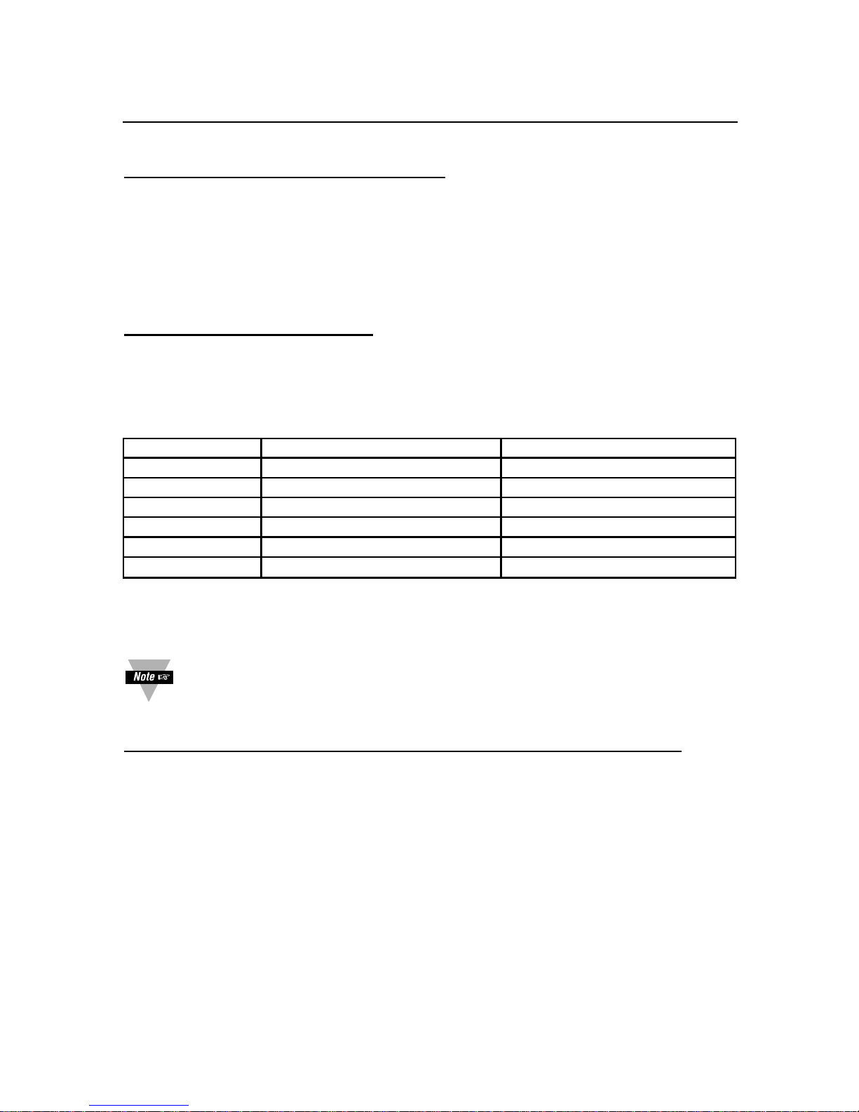
9-3
9.2 POINT-TO-POINT CONTINUOUS MODE
As described before, the meter transmits its different measurement values in strings of
characters continuously on the bus. The length of the string is variable and is
controlled by two menu items: “DAt.FMt” and “bUS.FMt” (see Sections 10.12 and
10.13). The time between consecutive transmission is also controlled by another menu
item: “SERCNt”. This item is in units of “numbers of readings” (Section 10.20).
9.2.1 METER’S RESPONSE TIME
This is the difference in time from the moment when the Serial Count (“SERCNt”)
value is reached to the time of transmission of the first character of the data string.
TABLE 9.2 READING RATE FOR COMMUNICATION
Sample Rate Process (100mV) Rate (ms) TC (K type) Rate (ms)
0 (slow) 7(135) 7(135)
1 14(68) 14(68)
2 27(36) 27(36)
3 52(19) 33(30)
4 71(14) 33(30)
5 (fast) 71(14) 33(30)
Test with Communication (Baud Rate at 19200 bps, Continuous Mode)
Although transmission’s program delay seems longer than chunk
transmission, in most cases total transmission time will be shorter, especially
using 19200 baud rate.
9.2.2 COMMUNICATING WITH THE METER WHEN IN CONTINUOUS MODE
If the meter is in point-to-point continuous mode, it ignores any transmitting command.
On the other hand, transmitting “X-OFF” character (13 Hex) which is equivalent to the
“RTS line false” will halt continuous transmission. Transmitting “X-ON” character
(11 hex) or making “RTS line true” will resume continuous transmission. Specifically, if
command “^AE” is transmitted, it will cause the meter to switch to COMMAND mode.
To be able to communicate with the meter when in Continuous Mode, do the following:
1. Transmit “X-OFF” character or make “RTS” line false.
2. Transmit “^AE” command. Now your meter is in Command Mode.
3. Do the communication with the meter.
4. Use “P1C” command to change BUS FORMAT (see Section 10.13) i.e., change
bit #4 of “bUS FMt” from 1 to 0 to go back to Continuous Mode
9. Meter Bus Response
Page 47

9-4
9. Meter Bus Response
9.3 MULTIPOINT ALARM MODE RESPONSE
The meter is commanded into the ALARM mode by detecting the alarm code–E03 after
its own address or the common 00 address. It stays silent unless an alarm already
exists. If an alarm is detected, it immediately transmits its own address with its alarm
status characters. No turnaround time delay is used. All devices on the bus which are
in the ALARM mode drop out of that mode if any character is detected on the bus, so
that bus contention is minimized.
The program for the controlling device (computer) is usually written to poll the alarm
status of all devices once bus activity is detected after an alarm command, so that
nearly-simultaneous alarm conditions are properly detected. Such a meter poll by the
computer after an alarm response usually starts at the detected device address, or at
device 01 in case of a garbled address (if two or more devices alarm at once).
If there is adequate time allowance in the data acquisition program, the computer may
poll the alarm status of all meters before commanding the ALARM mode to reduce the
probability of bus contention and garbled transmissions.
a) Slow mode = 0 to 300 ms
b) fast mode = 0 to 100 ms
Although transmission’s program delay seems longer than chunk
transmission, in most cases total transmission time will be shorter, specially
using 19200 baud rate.
9.4 WATCHDOG TIMER FOR COMMUNICATION
There is an eight second watchdog timer available in the communication portion of the
meter. When the computer starts sending a command to the meter, meter enables its
receive mode and starts getting the incoming characters, until a carriage return
completes the command string. Then the meter disables its receive mode and enables
its transmission mode to transmit or act according to the command information.
Receive mode time is the period that the meter is in receive mode. Receive time
should always be less than eight seconds, otherwise meter will ignore the command
and will finish the receive mode (there will be no affect on the performance of the
meter). In this case command should be executed again.
Watchdog timer is disabled when meter is in continuous communication
mode.
Page 48

10-1
10. Data Format Commands (P, G, R, W)
This section introduces data formats in detail. The following conditions are assumed in
the text and in examples in this section
1. The recognition character is the asterisk(*).
2. The meter address number is 15 HEX (21 decimal)
3.
When “W” command is given, a reset is necessary to initiate the command.
4.
“X” in bit pattern information means the bit is not related to that parameter.
5. Each byte consists of 8 bits.
6. Each byte consists of 2 nibbles; Most Significant Nibble (MSN) and Least
Significant Nibble (LSN)
Page 49

10-2
10. Data Format Commands (P, G, R, W)
10.1 READING CONFIGURATION (“RdG.CNF”)
TABLE 10.1 READING CONFIGURATION
BIT POSITION RdG.CNF
76543210
0 dIRECt Direct Format for Rd.SC.OF
1 2.CdINt 2-Coordinate Format for Rd.SC.OF
0 dP.ACtV yES Active Decimal Point
1 dP.ACtV NO Independent Decimal Point
0 SP1.FLS dISABL SP1 Flashing
1 SP1.FLS ENAbLE SP1 Flashing
0 SP2.FLS dISABL SP2 Flashing
1 SP2.FLS ENAbLE SP2 Flashing
0 AL1.FLS dISABL AL1 Flashing
1 AL1.FLS ENAbLE AL1 Flashing
0 AL2.FLS dISABL AL2 Flashing
1 AL2.FLS ENAbLE AL2 Flashing
00 H.bRt HIGH BRIGHTNESS
01 M.bRt MEDIUM BRIGHTNESS
10 L.bRt LOW BRIGHTNESS
1 1 (Not Used)
EXAMPLE: To set Rd.SC.OF direct format, Decimal Point active, Display flashing as
input value reaches SP1 or Alarm1 (SP3) and Display LED’s at high brightness level:
The command data is 00010100 BIN. = 14 HEX. Then send *W0714
Page 50

10-3
10. Data Format Commands (P, G, R, W)
10.2 INPUT CONFIGURATION (“INP.CNF” and “INPUt”)
TABLE 10.2 INPUT CONFIGURATION
BIT POSITION INP.CNF and INPUt
76543210
0 60 Line Frequency 60Hz
1 50 Line Frequency 50Hz
0 SLOW (14/SEC) Reading Rate
1 FAST (100/SEC) Reading Rate
0 UNIPOL Voltage Unipolar; tC
1 BIPOL Voltage Bipolar
00 C Unit of Temperature Degree C
01 F Unit of Temperature Degree F
10 k Unit of Temperature Degree K
1 1 (Not Used)
0 tC.CO.JC ENAbLE TC Cold Junction;
3.LINR 3 wire linear RTD;
NORMAL Bridge Limit; Process (Not Used)
1 tC.CO.JC dISABL TC Cold Junction;
4.LINR 4 wire linear RTD ;
SP1.L2.H SP1 lower overload limit and SP2
upper overload limit; Process - (Not Used)
0 IN.SC.OF dISABL Input Scale & Offset
1 IN.SC.OF ENAbLE Input Scale & Offset
0 RAtIO dISABL Strain Non-Ratiometric;
TC & Process Default
1 RAtIO ENAbLE Strain Ratiometric
EXAMPLE: To set the meter with line frequency of 50 Hz, slow reading rate (in case of
MENU 2), degree K unit of measure, TC Cold-Junction enabled (in case of TC mode)
and input scale and offset enabled:
The command data is 01010001BIN. = 51 HEX. Then send *W0A51
Page 51

10-4
10. Data Format Commands (P, G, R, W)
10.3 SETTING COUNT BY (“CNtby”) AND DECIMAL POINT (“SEt dP”)
TABLE 10.3 COUNT BY and DECIMAL POINT
BIT POSITION CNtby and SEt dP
76543210
000001 Count By 1
001002 Count By 2
010005 Count By 5
011020 Count By 10
100020 Count By 20
101050 Count By 50
110100 Count By 100
1 1 1 (Not Used)
X (Not Used)
0 0 0 NONE
001 FFFFFF
010 FFFFF.F
011 FFFF.FF
100 FFF.FFF
101 FF.FFFF
110 F.FFFFF
1 1 1 (Not Used)
X (Not Used)
EXAMPLE: To set the meter’s display decimal point at the 4th position (FFF.FFF) and
reading value counted by 2:
The command data is 01000001BIN. = 41 HEX. Then send *W0C41
Page 52

10-5
10. Data Format Commands (P, G, R, W)
10.4
FILTER CONFIGURATION “FILtER” AND “
OUt.tyP”
TABLE 10.4 FILTER CONFIGURATION and OUTPUT TYPE
BIT POSITION FILtER and OUt.tyP
76543210
000001 Filter Time 1
001002 Filter Time 2
010004 Filter Time 4
011008 Filter Time 8
100016 Filter Time 16
101032 Filter Time 32
110064 Filter Time 64
111128 Filter Time 128
X (Not Used)
0 A.b.C.FIL ABC Filter Type
1 MOV.AVE Moving Average Filter Type
1 FILtRd Filtered Value on the Display
00 UNFILt Unfiltered Value to Analog Output
01 FILtRd Filtered Value to Analog Output
10 PEAk Value to Analog Output
11 VALLy Value to Analog Output
EXAMPLE: To set the meter’s display with a rapid changing input signal the filter time
constant should be higher (for example FILt.tM = 32), switch Filter Type to MOV.AVE,
and set Output Type to be filtered:
The command data is 01110101BIN. = 75 HEX. Then send *W0E75
Page 53

10-6
10. Data Format Commands (P, G, R, W)
10.5 SETPOINT 1 AND 2 CONFIGURATION (“SP.CNF”)
Table 10.5 Setpoint Configuration
BIT POSITION SP.CNF
76543210
0 AbOVE SP1 Active Above
1 bELOW SP1 Active Below
0 N.OPEN SP1 Normal Open
1 N.CLOSE SP1 Normal Close
0 SP1 Use Un-filtered Value
1 SP1 Use Filtered Value
0 AbOVE SP2 Active Above
1 bELOW SP2 Active Below
0 N.OPEN SP2 Normal Open
1 N.CLOSE SP2 Normal Close
0 SP2 Use Un-filtered Value
1 SP2 Use Filtered Value
0 SP1 & SP2 Enable
1 SP1 & SP2 Disable
0 LED1 & 2 Enable
1 LED1 & 2 Disable
EXAMPLE: Set Setpoint 1 (SP1) active above, Relay 1 at normal close, Setpoint 2
(SP2) active below, Relay 2 at normal open, enable SP1 and SP2’s function, and
LED’s light up when input signal filtered value reaches the Setpoint 1 and 2:
The command data is 00101110BIN. = 2E HEX. Then send *W102E
Page 54

10-7
10. Data Format Commands (P, G, R, W)
10.6 ALARM (SETPOINTS 3 AND 4) CONFIGURATION (“AL.CNF”)
TABLE 10.6 ALARM CONFIGURATION
BIT POSITION AL.CNF
76543210
0 AbOVE AL1 Active Above
1 bELOW AL1 Active Below
0 N.OPEN AL1 Normal Open
1 N.CLOSE AL1 Normal Close
0 AL1 Use Un-Filtered Value
1 AL1 Use Filtered Value
0 AbOVE AL2 ACTIVE Above
1 bELOW AL2 ACTIVE Below
0 N.OPEN AL2 Normal Open
1 N.CLOSE AL2 Normal Close
0 AL2 Use Un-Filtered Value
1 AL2 Use Filtered Value
0 AL1 & AL2 Enable
1 AL1 & AL2 Disable
0 ALARM RESET Enable AT P2-11
1 ALARM RESET Disable AT P2-11
EXAMPLE: To enable Alarm 1 & 2 and setup Alarm1 to activate above Alarm 1 value,
Relay at normal open and use of filtered input value. However, set Alarm 2 to activate
below Alarm 2 value, Relay at normal close, use of unfiltered input value and Alarm
reset disabled at pin#11 of rear terminal P2:
The command data is 10011100 BIN. = 9C HEX. Then send *W119C
Page 55
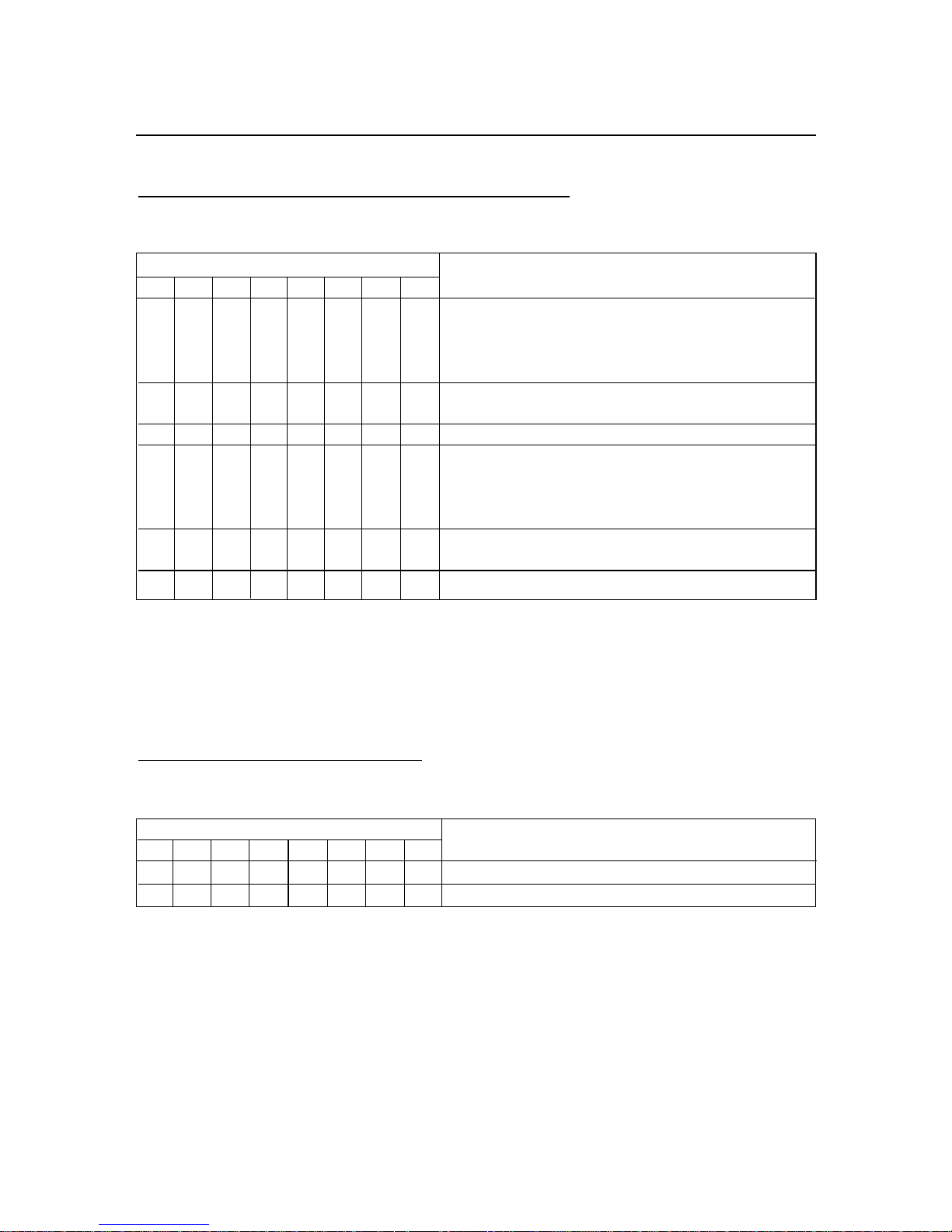
10-8
10. Data Format Commands (P, G, R, W)
10.7 ALARM FUNCTIONS (“AL.CNF and AL.MOdE”)
TABLE 10.7 ALARM CONFIGURATION AND MODE
BIT POSITION AL.CNF and AL.MOdE
76543210
00PROC AL1 Process
01HI dEV AL1 HIGH Deviation
10LO dEV AL1 LOW Deviation
11bNd.dEV AL1 BAND Deviation
0 UNLtCH AL1 Un-Latched Alarm
1 LAtCH AL1 Latched Alarm
X (Not Used)
00 PROC AL2 Process
01 HI dEV AL2 HIGH Deviation
10 LO dEV AL2 LOW Deviation
11 bNd.dEV AL2 BAND Deviation
0 UNLtCH AL2 Un-Latched Alarm
1 LAtCH AL2 Latched Alarm
X (Not Used)
EXAMPLE: Set Alarm 1 function mode as Band Deviation, latched and Alarm 2
function mode as Process, latched.
The command data is 01000111 BIN. = 47 HEX. Then send *W1247
10.8 ALARM DELAY: (“NUM.dLy”)
TABLE 10.8 ALARM DELAY
BIT POSITION NUM.dLy (ALARM DELAY)
76543210
XXXX0-15 for AL2
XXXX 0-15 for AL1
EXAMPLE: These 2 bytes enable users to select the number of input readings
required to trigger Alarm 1 (SP3), and Alarm 2 (SP4) action that will delay the alarm
activation. Choose 7 for Alarm 2 and 9 for Alarm 1 as the number of input readings
before meter activates the alarm:
The command data is 10010111 BIN. = 97 HEX. Then send *W1397
Page 56

10-9
10. Data Format Commands (P, G, R, W)
10.9 OUTPUT CONFIGURATION (“OUt.CNF”) and A to D RATE (“Ad.RAtE”)
TABLE 10.9 OUTPUT CONFIGURATION
BIT POSITION OUt.CNFand Ad.RAtE
76543210
0 dISABLE Analog Output
1 ENAbLE Analog Output
0 0-10 V Output
1 0-20 mA Output
0 Parallel BCD dISABL (not used)
1 Parallel BCD ENAbLE (not used)
0 BCD Output Display Value (not used)
1 BCD Output Peak Value (not used)
0 Standard Print (Desktop) (not used)
1
Special Printer (Panel Printer) (not used)
000 0 A to D Convert Rate 0
001 1 A to D Convert Rate 1
010 2 A to D Convert Rate 2
011 3 A to D Convert Rate 3
100 4 A to D Convert Rate 4
101 5 A to D Convert Rate 5
1 1 0 (Not Used)
1 1 1 (Not Used)
EXAMPLE: Enable Analog Output, which produces a 0-20 mA current source and set
the A to D conversion rate to 2:
The command data is 01000011 BIN. = 43 HEX. Then send *W1643
Page 57

10-10
10. Data Format Commands (P, G, R, W)
10.10 INPUT TYPE (“INPUt”) and READING SCALE & OFFSET (“Rd.SC.OF”)
TABLE 10.10 INPUT TYPE and READING SCALE & OFFSET
BIT POSITION INPUt and Rd.SC.OF
76543210
0000TC: J; RTD: 2Pt392 2 wire 100ohm a=392;
Process:+/-50mV, 0-100mV; Current: 0-20mA
0001TC: K; RTD: 3Pt392 3 wire 100ohm a=392;
Process: +/-500mV, 0-1V; Current: 4-20mA
0010TC: T; RTD: 4Pt392 4 wire 100ohm a=392;
Process: +/-5V, 0-10V
0011TC: E; RTD: 2Pt385 2 wire 100ohm a=385;
Process: +/-50V, 0-100V
0100TC: N; RTD: 3Pt385 3 wire 100ohm a=385
0101TC: DINJ; RTD: 4Pt385 4 wire 100ohm a=385
0110TC: R; RTD: 3.LINR 3 wire Linear or Ohms
0111TC: S; RTD: 4.LINR 4 wire Linear
1000TC: B
000 TC
001 Rtd
010 VOLt
011 CURRNt
1 0 0 (Not Used)
101 bRIdGE
110 POt
1 1 1 (Not Used)
0 Rd.SC.OF dISAbL
1 Rd.SC.OF ENAbLE
EXAMPLE: To select 0-100 Volt range input type and enable Reading Scale and Offset :
The command data is 10100011 BIN. = A3 HEX. Then send *W05A3
Page 58

10-11
10. Data Format Commands (P, G, R, W)
10.11 SERIAL COMMUNICATIONS CONFIGURATION (“COMM”)
TABLE 10.11 SERIAL COMMUNICATIONS CONFIGURATION
BIT POSITION COM.PAR and MOdbUS
76543210
0 0 0 Baud Rate 300
0 0 1 Baud Rate 600
0 1 0 Baud Rate 1200
0 1 1 Baud Rate 2400
1 0 0 Baud Rate 4800
1 0 1 Baud Rate 9600
1 1 0 Baud Rate 19200
1 1 1 (Not Used)
0 MODBUS Disable
1 MODBUS Enable
0 0 NONE PARITY
0 1 ODD PARITY
1 0 EVEN PARITY
1 1 (Not Used)
0 ONE STOP BIT
1 TWO STOP BIT
X (Not Used)
EXAMPLE: To set the baud rate to 19200, enable Modbus, None Parity and one stop bit:
The command data is 00001110 BIN. = 0E HEX. Then send *W180E
Page 59

10-12
10. Data Format Commands (P, G, R, W)
10.12 DATA FORMAT (“dAt.FMt”)
TABLE 10.12 DATA FORMAT
BIT POSITION DAt.FMt
76543210
0 Alarm Status - EXCLUDED
1 Alarm Status - INCLUDED
0 Peak / Valley Status - EXCLUDED
1 Peak / Valley Status - INCLUDED
0 Current Reading - EXCLUDED
1 Current Reading - INCLUDED
0 Filtered Value - EXCLUDED
1 Filtered Value - INCLUDED
0 Peak Value - EXCLUDED
1 Peak Value - INCLUDED
0 Valley Value - EXCLUDED
1 Valley Value - INCLUDED
0 Use Space as Separator
1 Use <CR. as Separator
0 Units of Measurement - EXCLUDED
1 Units of Measurement - INCLUDED
EXAMPLE: To format the data string, which includes Alarm status, Peak/Valley,
Current, Filtered input value status, units of measure and listed by underline instead of
space separated:
The command data is 11001111 BIN. = CF HEX. Then send *W1BCF
Page 60

10-13
10. Data Format Commands (P, G, R, W)
10.13 COMMUNICATIONS BUS FORMAT (“bUS.FMt”)
TABLE 10.13 BUS FORMAT
BIT POSITION bUS.FMt
76543210
0 Checksum - EXCLUDED
1 Checksum - INCLUDED
0 NO Line Feed
1 Line Feed following with <CR.
0 NO ECHO
1 ECHO
0 Point to Point Mode (RS-232)
1 Multi-Point (RS-485)
0 CONTINUOUS (Point to Point Mode)
1 COMMAND
0 MESSAGE (Continuous MODE)
1 CHARACTER (Continuous MODE)
0 RS-232
1 RS-485
0 ALWAYS 0, (Not Used)
EXAMPLE: To configure communication protocol and bus format as following:
checksum excluded, no line feed, echo mode on, point to point, command mode and
RS-232 protocol:
The command data is 00010100 BIN. = 14 HEX. Then send *W1C14
Page 61

10-14
10. Data Format Commands (P, G, R, W)
10.14 LOCKOUT CONFIGURATION (“LCk.CNF”)
TABLE 10.14 LOCKOUT CONFIGURATION
BIT POSITION LCk.CNF
76543210
0 SP1 LOCKOUT: UNLOCK
1 LOCK
0 SP2 LOCKOUT: UNLOCK
1 LOCK
0 AL1 LOCKOUT: UNLOCK
1 LOCK
0 AL2 LOCKOUT: UNLOCK
1 LOCK
0 INPUt LOCKOUT: UNLOCK
1 LOCK
0 RdG.CFG LOCKOUT: UNLOCK
1 LOCK
0 INP.CFG LOCKOUT: UNLOCK
1 LOCK
0 MP.SC.OF LOCKOUT: UNLOCK
1 LOCK
EXAMPLE: To prevent unauthorized modification of Setpoint 1 (SP1), Input type,
Reading Configuration menu and Multi-Point Scale and Offset menu:
The command data is 10110001 BIN. = 14 HEX. Then send *W01B1
Page 62

10-15
10.15 LOCKOUT CONFIG. (“LCk.CNF”) and NORMAL COLOR (“N.COLOR”)
TABLE 10.15 LOCKOUT CONFIGURATION and NORMAL COLOR
BIT POSITION LCk.CNF and N.COLOR
76543210
0 OUt.CNF LOCKOUT: UNLOCK
1 LOCK
0 SP.CNF LOCKOUT: UNLOCK
1 LOCK
0 AL.CNFG LOCKOUT: UNLOCK
1 LOCK
0 COMM LOCKOUT: UNLOCK
1 LOCK
0 COLOR LOCKOUT: UNLOCK
1 LOCK
0/1 (Not Used)
0 0 NORMAL COLOR: GREEN
0 1 NORMAL COLOR: RED
1 0 NORMAL COLOR: AMBER
1 1 (Not Used)
EXAMPLE: To prevent unauthorized access to Output Configuration menu,
Communication menu and select Normal color of the LED’s display as Green:
The command data is 00001001 BIN. = 09 HEX. Then send *W0209
10. Data Format Commands (P, G, R, W)
Page 63
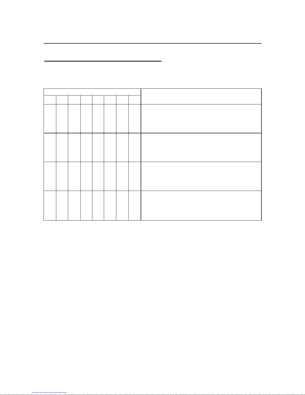
10-16
10. Data Format Commands (P, G, R, W)
10.16 COLOR CONFIGURATION (“COLOR”)
TABLE 10.16 COLOR CONFIGURATION
BIT POSITION COLOR
76543210
0 0 SP1 COLOR: HOLD
0 1 SP1 COLOR: GREEN
1 0 SP1 COLOR: RED
1 1 SP1 COLOR: AMBER
0 0 SP2 COLOR: HOLD
0 1 SP2 COLOR: GREEN
1 0 SP2 COLOR: RED
1 1 SP2 COLOR: AMBER
0 0 AL1 COLOR: HOLD
0 1 AL1 COLOR: GREEN
1 0 AL1 COLOR: RED
1 1 AL1 COLOR: AMBER
0 0 AL2 COLOR: HOLD
0 1 AL2 COLOR: GREEN
1 0 AL2 COLOR: RED
1 1 AL2 COLOR: AMBER
EXAMPLE: To setup LED’s display change color to RED then AMBER when reading
reaches SP1 value then AL1 (SP3) value respectively, but hold the color for SP2 or
AL2:
The command data is 00110010 BIN. = 32 HEX. Then send *W0332
Page 64

10-17
10. Data Format Commands (P, G, R, W)
10.17 BLOCK A
BLOCK COMMAND PREFIX COMMAND SUFFIX (HEX)
A R,W 40
NOTE: R,W means “R” or “W”
This block consists of ten (10) items and thirty bytes (60 ASCII characters):
TABLE 10.17 R/W40 (BLOCK A)
*W40200000100001200000100001200000100001200000200000200000200000
HEX BYTE NUMBER DEFAULT
COMMAND DESCRIPTION NUMBER OF VALUE
SUFFIX & ORDER BYTE
26 Analog Out Offset 1, 2, 3 3 200000
17 Analog Out Scale 4, 5, 6 3 100001
25 Input Offset 7, 8, 9 3 200000
0B Input Scale 10, 11, 12 3 100001
09 Reading Display Offset 13, 14, 15 3 200000
08 Reading Display Scale 16, 17, 18 3 100001
24 Setpoint 4 Value 19, 20, 21 3 200000
23 Setpoint 3 Value 22, 23, 24 3 200000
22 Setpoint 2 Value 25, 26, 27 3 200000
21 Setpoint 1 Value 28, 29, 30 3 200000
Page 65
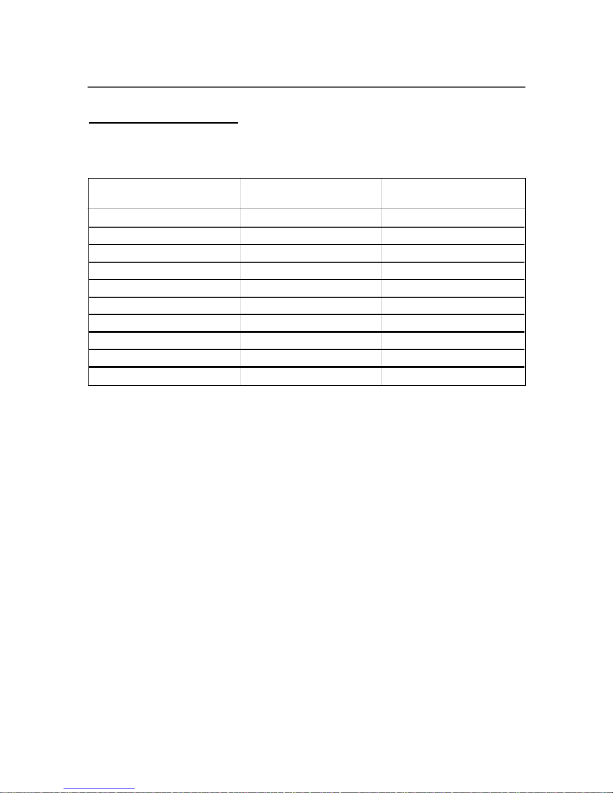
10-18
10. Data Format Commands (P, G, R, W)
10.17 BLOCK A continued
EXAMPLE: To configure meter working with the following order and desired options:
FUNCTIONS DESIRED OPTIONS EQUIVALENT
HEX VALUE
Analog Out Offset 0 700000
Analog Out Scale 0.0001 A186A0
Input Offset 0 700000
Input Scale 1 6186A0
Display Offset 0 700000
Display Scale 1 6186A0
Setpoint 4 Value +40000. 109C40
Setpoint 3 Value +30000. 107530
Setpoint 2 Value +20000. 104E20
Setpoint 1 Value +10000. 102710
The command data is in order as following:
700000A186A07000006186A07000006186A0109C40107530104E20102710
Then send:
*W40700000A186A07000006186A07000006186A0109C40107530104E20102710
Page 66

10-19
10. Data Format Commands (P, G, R, W)
10.18 BLOCK B
BLOCK COMMAND PREFIX COMMAND SUFFIX (HEX)
B R,W 41
NOTE: R,W means “R” or “W”
This block consists of 17 items and 19 bytes (38 ASCII characters):
TABLE 10.18 R/W41 (BLOCK B)
*W412A202020010115030000002000000894040000
HEX BYTE NUMBER DEFAULT
COMMAND DESCRIPTION NUMBER OF VALUE
SUFFIX & ORDER BYTE
1E Recognition Charater 1 1 2A
1F Units of Measure 2, 3, 4 3 202020
20 Serial Delay 5 1 01
1A RS-485 Device Address 6 1 01
18 COM.PAR and MOdbUS 7 1 15
13 NUM.dLy (Alarm Delay) 8 1 33
12 AL.CNF and AL.MOdE 9 1 00
11 AL.CNF 10 1 00
10 SP.CNF 11 1 00
05 INPUt and Rd.SC.OF 12 1 00
0C CNt.by and dEC.Pt 13 1 00
16 OUt.CNF and Ad.RAtE 14 1 00
07 RDG.CNF 15 1 08
1C BUS.FMt 16 1 94
1B dAt.FMt 17 1 04
0E FILtER 18 1 00
0A INP.CNF 19 1 00
Page 67
10-20
10. Data Format Commands (P, G, R, W)
10.18 BLOCK B continued
R/W41 (BLOCK B)
EXAMPLE: To configure meter working with following order and desired options:
FUNCTIONS DESIRED OPTIONS EQUIVALENT
HEX. VALUE
Recognition Character ! 21
Units of Measure mV 6D5600
Serial Delay 100msec. 02
RS-485 Device address 15 0F
COM.PAR & MOdbUS Comm. Parameter: (19.2k, none, 1)
Modbus enabled 0E
NUM.dLy (Alarm Delay) 7 for Alarm 2, 9 for Alarm1 97
AL.CNF & AL.MOdE AL1: Band Dev., latched;
AL2: Process, latched 47
AL.CNF AL1 & AL2 enabled, AL1:above,
normal open, filtered; AL2: below,
normal closed, unfiltered 9C
AL. Reset disabled at P2-11 rear connector.
SP.CNF SP1 & SP2 enabled and flashing;
SP1: above, normal close; 2E
SP2: below, normal open,
INPUt & Rd.SC.OF 0-100 Volt, and enable Rd.SC.OF A3
CNt by & dEC.Pt FFF.FFF 41
OUt.CNF & Ad.RAtE Enabled Analog Output,
0-20mA and A2D conversion rate = 2 43
RdG.CNF Rd.SC.OF direct format,
Decimal Point active,
Display Flashing at Alarm or Setpoint state 14
and LED’s display at high brightness level.
bUS.FMt Checksum excluded, No line feed,
Echo mode on, P-to-P Command mode, 54
RS-485 protocol
DAt.FMt Data String will include:
Alarm / Peak / Valley / current filtered CF
input value status and separated by line.
FILtER 32 75
INP.CNF Line Frequency - 60HZ,
FAST (12/SEC) Reading Rate, 1A
UNIPOLAR, IN.SC.OF- ENABLE
*The command data is in order as follows:
6D5600020F0E97479C2EA341431454CF
Then send: *W416D5600020F0E97479C2EA341431454CF
Page 68
10-21
10. Data Format Commands (P, G, R, W)
10.19 BLOCK C
BLOCK COMMAND PREFIX COMMAND SUFFIX (HEX)
C R,W 42
NOTE: R,W means “R” or “W”
This block consists of 7 items and 10 bytes (20 ASCII characters):
TABLE 10.19 R/W42 (BLOCK C)
*W4200010014001400000000
HEX BYTE NUMBER DEFAULT
COMMAND DESCRIPTION NUMBER OF VALUE
SUFFIX & ORDER BYTE
1D SERCNt (Serial Count) 1, 2 2 0001
15 AL db (value) 3, 4 2 0014
14 SP db 5, 6 2 0014
04 (Reserved) 7 1 00
03 COLOR (Color Config) 8 1 00
02 LCk.CNF / N.COLOR 9 1 00
01 LCk.CNF 10 1 00
EXAMPLE: To configure meter working with following order and desired options:
FUNCTIONS DESIRED OPTIONS EQUIVALENT
HEX. VALUE
SERCNt Fast Rate (12readings/SEC)/hour or A8C0
(12x60x60=43200: # of reading between transmission)
AL db 0030 001E
SP db 0030 001E
(Reserved) 00 00
COLOR LED’s display changes color to RED then AMBER
when reading reaches SP1 value then AL1 (SP3) value 32
respectively, but hold the color for SP2 or AL2.
LCk.CNF / Lock menus and Green for Normal LED’s display color. 09
N.COLOR
LCk.CNF Prevent unauthorized modification of SP1, input type,
RdG.CNFand MP.SC.OF menus 47
The command data is in order as follows: A8C0001E001E00320947
Then send: *W42A8C0001E001E00320947
Page 69

10-22
10. Data Format Commands (P, G, R, W)
10.20 BLOCK D
R/W43, 44, 45, 46, 47, 48 are reserved by factory. It is not recommended that
that the customer perform these commands.
TABLE 10.20 R/W43 (BLOCK D)
*To write default value:
W43000000000000000000008000000000008000800000008000000080000640
BYTE NUMBER DESCRIPTION NUMBER OF DEFAULT
& ORDER BYTE VALUE
1,2 Analog out mA Scale factor 2 0000
3,4 Analog out mA offset factor 2 0000
5,6 Analog out Volt Scale factor 2 0000
7,8 Analog out Volt offset factor 2 0000
9,10 QD-Online 2 0000
11,12 Cal. Current Scale 2 8000
13,14 Cal. Current Offset 2 0000
15,16 (Reserved) 2 0000
17,18 Cal. Bridge 2 8000
19,20 Cal. Ratio Scale 2 8000
21,22 Cal. Ratio Offset 2 0000
23,24 Cal. Quasi Scale 2 8000
25,26 Cal. Quasi Offset 2 0000
27,28 Cal. Howland Pump fine 2 8000
29,30 Cal. Howland Pump 2 0640
Page 70
10-23
10. Data Format Commands (P, G, R, W)
10.21 R/W44 (BLOCK E)
To write default value:
W44800000008000000080000000800000008000000080000000
TABLE 10.21 R/W44 (BLOCK E)
BYTE NUMBER DESCRIPTION NUMBER OF DEFAULT
& ORDER BYTE VALUE
1,2 500mV Scale 2 8000
3,4 500mV Offset 2 0000
5,6 5 V Scale 2 8000
7,8 5 V Offset 2 0000
9,10 50V Scale 2 8000
11,12 50V Offset 2 0000
13,14 1 V Scale 2 8000
15,16 1 V Offset 2 0000
17,18 10 V Scale 2 8000
19,20 10 V Offset 2 0000
21,22 100 V Scale 2 8000
23,24 100 V Offset 2 0000
10.22 R/W45 (BLOCK F)
To write default value: W450000
TABLE 10.22 R/W45 (BLOCK F)
BYTE NUMBER DESCRIPTION NUMBER OF DEFAULT
& ORDER VALUE
1,2 Cal. Quasi Offset 2 0000
10.23 R46
This command is for the channel one of A/D.
10.24 R47
This command is for the channel two of A/D
10.25 R48
This command is for the channel three of A/D
Page 71

10-24
10. Data Format Commands (P, G, R, W)
10.26 R/W50 TABLE 10.23 R/W50
Hex Number Default
Command DESCRIPTION of Byte Value
Suffix
1st Byte: MENU1 and MENU2
50 (SetColor.CNF) selector 2 0400
2nd Byte: NUM.PNt value of MP.SC.OF
TABLE 10.24 R/W50 NUM.PNt and MENU selection
BIT POSITION FUNCTION
15141312111098765 43210
2nd Byte:
NUM.PNt value of
000 00000MP.SC.OF
1st Byte:
MENU1 &
MENU2
(Set Color Config)
00 GREEN
01 REd
10 AMbER
1 1 (Not Used)
0 MENU1
1 MENU2
0 0 0 0 0 Normal default
Operation/Menu
selection disabled
1 1 1 1 1 NEW Menu default
UPDATE / Enabled
Menu Type selection
Initialization. (*)
(*) Menu Type Selection Initialization:
If the 1st byte of command data is set (remotely) 11111XXX, the selected menu (either
MENU1 or MENU2) will be written to the EEPROM and default configuration is
automatically loaded. This 1st byte also resumes the state (00000XXX) of normal
default operation or disables the Menu Type selection mode after the selected menu
embedded.
EXAMPLE: To select MENU1 from MENU2, send this following command:
*W50FC00
That will update the menu to new menu with default value items. The last two
characters represent the default value of NUM.PNt for MP.SC.OF (Multi-Point Scale &
Offset).
Page 72
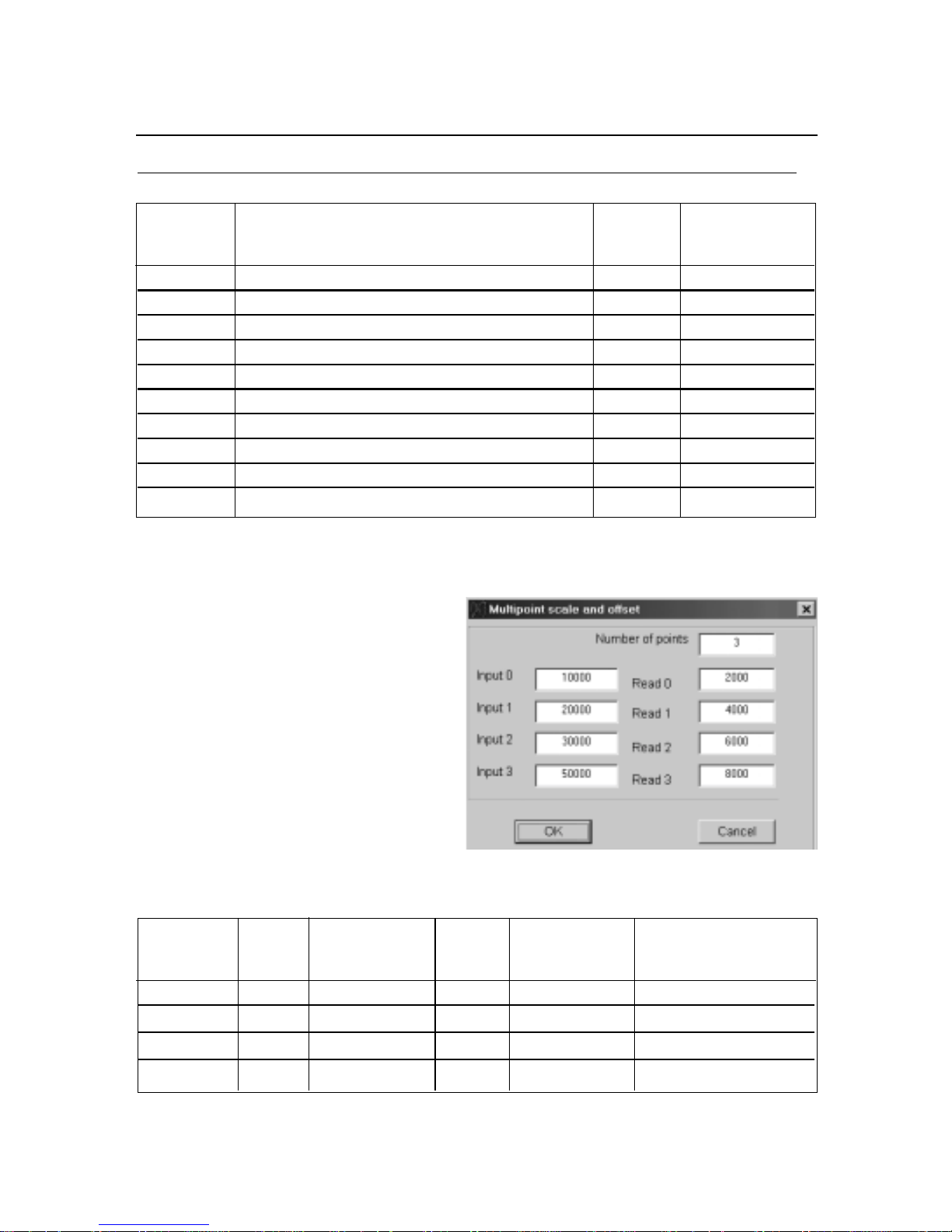
10-25
10. Data Format Commands (P, G, R, W)
10.27
R/W51, R/W52, R/W53, R/W54, R/W55, R/W56, R/W57, R/W58, R/W59, R/W5A:
TABLE 10.25 *R/W5XXXXX
HEX DESCRIPTION NUMBER DEFAULT
COMMAND 1st 3 bytes = Read0 value of BYTES VALUE
SUFFIX 2nd 3 bytes = Input0 value
51 MP.SC.OF Read/Input 0 values = Pointer 0 6 200000200000
52 MP.SC.OF Read/Input 0 values = Pointer 1 6 200000200000
53 MP.SC.OF Read/Input 0 values = Pointer 2 6 200000200000
54 MP.SC.OF Read/Input 0 values = Pointer 3 6 200000200000
55 MP.SC.OF Read/Input 0 values = Pointer 4 6 200000200000
56 MP.SC.OF Read/Input 0 values = Pointer 5 6 200000200000
57 MP.SC.OF Read/Input 0 values = Pointer 6 6 200000200000
58 MP.SC.OF Read/Input 0 values = Pointer 7 6 200000200000
59 MP.SC.OF Read/Input 0 values = Pointer 8 6 200000200000
5A MP.SC.OF Read/Input 0 values = Pointer 9 6 200000200000
EXAMPLE: If Pointer 0 is read as with this command *R51 and the response is
R51200000200000, it means that:
2nd 3 bytes is Input0 value = 200000
1st 3 bytes is Read0 value = 200000
EXAMPLE: To setup Multi-Point Scale &
Offset with NUM.PNt = 3 as desired as
following and shown below:
Converting the decimal values to hex. values and send the Write Commands as listed
as following:
HEX. EQUIVALENT EQUIVALENT WRITE
COMMAND FOR HEX. VALUE FOR HEX. VALUE COMMAND
SUFFIX
51 Read 0 1007D0 Input 0 102710 W511007D0102710
52 Read 1 100FA0 Input 1 104E20 W52100FA0104E20
53 Read 2 101770 Input 2 107530 W53101770107530
54 Read 3 101F40 Input 3 10C350 W54101F4010C350
To enter the values of Pointer, the Sign and Decimal point must follow the manner
shown in Table 10.26.
Page 73

10-26
10. Data Format Commands (P, G, R, W)
10.28 SET SIGN AND DECIMAL POINT FORMAT
Command suffixes “21”, “22”, “23” and “24” set the value of Setpoints 1, 2, 3 and 4
respectively (the last two often used as Alarm 1 and 2). Each setpoint is described by
three bytes (six HEX-ASCII characters), with the sign and decimal point encoded in the
MSN:
(Here, “FFFFFF” represents the 6 displayed decimal digits, the magnitude of the 20
least-significant bits of these 3 bytes.)
1. Bits 0 to 19 belong to the absolute value (99999 for negative values and 999999 for
positive values)
2. Bits 20, 21, 22 belong to the decimalpoint as in Table 10.26
3. Bit 23 belongs to sign where 0 is positive and 1 is negative as in Table 10.26
TABLE 10.26 SETPOINT VALUES, BITS 23, 22, 21, AND 20
BIT PATTERN SIGN AND
23 22 21 20 DECIMAL POINT
0000 Not used
0001 +FFFFF.
0010 +FFFFF.F
0011 +FFFF.FF
0100 +FFF.FFF
0101 +FF.FFFF
0110 +F.FFFFF
0111 Not used
1000 Not used
1001 –FFFFFF
1010 –FFFFF.F
1011 –FFFF.FF
1100 –FFF.FFF
1101 –FF.FFFF
1110 –F.FFFFF
1111 Not used
The following 5 nibbles (HEX-ASCII characters) give the binary magnitude.
Since Setpoint value decimal point is directly related to the system decimal
point (see Section 10.3), select the same decimal for setpoints as selected
for system decimal point.
EXAMPLE: The computer inquires of meter #15 hex what value for Setpoint #3 is
stored in EEPROM (usually the same value as in RAM):
“*15R23<CR>”, and if set for echo (“BUS.FMt”), the meter replies:
“15R23A12345<CR>”, where the magnitude is “12345” in hex, or “74565” in decimal,
and the MSN “A”, from the Table 10.28, sets the final decimal value of Setpoint #3 as
“–7456.5”.
Page 74

10-27
10. Data Format Commands (P, G, R, W)
10.29 RS-485 METER “AddRES”
This “1A” command suffix uses 2 HEX-ASCII characters for the device address, but
that number is limited to the 1 to 199 decimal range (many more numbers than the 32device hardware limit).
EXAMPLE: The computer wants to renumber meter #15 HEX (#21 decimal) to #25
HEX(#37 decimal); it then puts the new address into EEPROM with:
“*15W1A25<CR>”
Which, if “BUS.FMt”, would be echoed by the meter with “15W1A<CR>”.
This new address would then be put into action by giving the meter a hard reset,
“RESET2”, from the front-panel, by external contact closure (see Section 10.12), or by
sending the reset with:
“*15Z04<CR>”.
That meter will no longer answer to the “15” hex address; it now responds commands
preceded by “*25”.
10.30 NUMBER OF READINGS BETWEEN EACH TRANSMISSION (“SER CNt”)
The “1D” command suffix data is the number of readings between transmissions; this
is used only for point-to-point continuous transmission. Four nibbles (2 bytes or 4 HEXASCII characters) are used; overflow detection limits the number of readings between
transmissions to 59999 (decimal).
“1D” values reside only in EEPROM, so only “R/W” command letters apply.
EXAMPLE: If you were on SLOW (approximately 3 readings/second) and wanted a
transmission every hour, the number of readings between transmissions would be
approximately 3*60*60 = 10800, or hex 2A30: to tell the meter, send:
“*W1D2A30<CR>”, which places the 2A30 into the EEPROM memory of the meter
(add a Hard Reset, “*Z04<CR>” to move this into RAM). If you have set “BUS.FMt”,
the meter will echo “W1D<CR>”.
Page 75

10-28
10. Data Format Commands (P, G, R, W)
10.31 RECOGNITION CHARACTER (SER.RCG)
You can change the security code for commands with this “1E” command suffix; the
ASCII table address (two HEX-ASCII characters) of the selected character is
transmitted.
Valid character addresses are from 20 hex to 7F hex (32 to 127 decimal) with the
exception of “^”, “A”, “E” characters.
EXAMPLE: To change the recognition character from “*” to “!” for all meters on the bus,
send:
“*00W1E21<CR>”, which puts that new code into EEPROM (but not automatically into
RAM), followed by “*00Z04<CR>”, which gives a hard reset to all the meters, moving
the new code into RAM. All meters will now ignore commands preceded by “*”, and
recognize those preceded with “!”.
10.32 UNITS OF MEASURE (SER.UOM)
When instructed with this “1F” command suffix, the meter will label its transmitted
values with three letters representing the units of the measured quantity (these are for
screen or printer labels, not for the meter display; the right-hand digit F, C or K units for
temperature are selected by “RdG.CNF”, Section 10.1).
Each letter is represented by the two HEX-ASCII characters giving its ASCII table
address, from “41” to “79” (all upper and lower case letters) or the <SP> address, “20”,
for a total of six transmitted characters (do not select any control characters for unitsof-measure).
When the desired units-of-measure to be printed have fewer than 3 characters, send
the <SP> address (“20”) to put the blank(s) in the chosen spot(s).
Note that the units-of-measure letters transmitted in the “V01” response are in plain
ASCII (one character each) in contrast with this command, where the six characters of
the addresses are sent.
EXAMPLE: The computer requests the RAM setting for the measurements underway
at meter #15 hex with:
“*15G1F<CR>”, and that meter, if “BUS.FMt”, responds with:
“15G1F6B5061<CR>”; the <data> here are “6B5061”, which is HEX-ASCII for “kPa”
(kiloPascals).
“00” is equivalent to “nul” and meter will transmit nothing for units of measure
if the first character is “0”.
Page 76
10-29
10. Data Format Commands (P, G, R, W)
10.33 TX/RX TURNAROUND DELAY (SERIAL DELAY SER.dLy)
The four choices provided by the meter for this “20”
command suffix only need two bits of storage, but the
standard byte (two nibbles) is used, so that the MSN = 0.
Turn-around delay is normally used on half-duplex
systems (e.g., RS-485), not on full duplex (for the
meter, RS-232 or RS-422), but the chosen amount is
applied to any of these by the meter. The delay can
be useful in eliminating the effects of ringing,
reflections or line drop.
EXAMPLE: The computer wants meter #15 hex to use a turn-around delay of 100
milliseconds:
“*15W2002<CR>”, and if set for echo with “BUS.FMt”, the meter replies:
“15W20<CR>”. If point-to-point (only one meter), the “15” address is not used. The
chosen delay is now stored in the EEPROM. To put it into use (move to RAM), send a
hard reset, “*15Z04<CR>”.
10.34
READING, INPUT, or OUTPUT SCALE FACTOR(“RdG SC”, “INP SC”, “OUt SC”)
These items are 3 bytes each (6 HEX- ASCII characters) and their corresponding
command suffixes are:
ITEM COMMAND SUFFIX (HEX)
RdG SC 08
IN SC 0B
OUt SC 17
All three scale factors can be calculated by the meter from entry of two data points (via
pushbutton or diskette); only Reading Scale permits direct entry (to facilitate 1.00000
and other straight-forward values). Scale factor and Offset values, however, are stored
separately inside the meter. If your scale/offset information is in the form of two data
points (O2,I2 and O1,I1, where the O’s are the Outputs for the I’s, Inputs), then
SC = (O2-O1) / (I2-I1)
This value is entered/read with these “08”, “0B” and “17” command suffixes, and also
used in calculating the corresponding Offsets (see Section 10.5 ).
True value for output scale factor is stored in its location in EEPROM. When
the program is running, it combines this value with calibration scale of analog
out board and stores new value in output scale’s RAM location (CALLED
MODIFIED OUTPUT SCALE). Therefore, “P17” for this scale factor should be
used very carefully (avoid using if possible). But with “G17”, the value of
modified output scale factor can be read.
Milliseconds of
BIT # Turnaround delay
000
0130
0 2 100
0 3 300
TABLE 10.27.
SERIAL DELAY (“SER.dLy”)
Page 77

10-30
10. Data Format Commands (P, G, R, W)
10.34 READING, INPUT, or OUTPUT SCALE FACTOR continued
The most significant nibble of the scale factor data sets the decimal point (power of 10
multiplier) for the least-significant nineteen bits, which give the magnitude using a righthand decimal point (decimal 499,999 full scale). The bit in between, #19, is the sign
bit, “0” for “+” and “1” for “-”, which is OR’d with the magnitude to get the HEX value of
the second nibble. The decimal-point code is given in Table 10.28. The figure “4”
indicates the maximum value in that position and “x” is any chosen decimal digit.
Bit pattern information is as follows:
1) Bits 0 to 18 belong to the absolute value.
2) Bits 20, 21, 22, 23, belong to decimal point as shown in Table 10.28.
3) Bit number 19 belongs to the sign and is “0” for positive and “1” for negative.
TABLE 10.28. READING SCALE (“RdG SC”), INPUT SCALE (“INP SC”), AND
OUTPUT SCALE (“OUt SC”) BITS 23, 22, 21 AND 20
BIT NUMBER DECIMAL POWER OF10
23 22 21 20 NUMBER MULTIPLIER
0 0 0 0 4xxxxx0. 1
0 0 0 1 4xxxxx.0 0
1 0 1 0 4xxxx.x0 -1
0 0 1 1 4xxx.xx0 -2
0 1 0 0 4xx.xxx0 -3
0 1 0 1 4x.xxxx0 -4
0 1 1 0 4.xxxxx0 -5
0 1 1 1 .4xxxxx0 -6
1 0 0 0 .04xxxxx0 -7
1 0 0 1 .004xxxxx0 -8
1 0 1 0 .0004xxxxx0 -9
1 0 1 1 .00004xxxxx0 -10
1 1 0 0 .000004xxxxx0 -11
1 1 0 1 .0000004xxxxx0 -12
1 1 1 0 .00000004xxxxx0 -13
1 1 1 1 .000000004xxxxx0 -14
EXAMPLE: Desired reading scale factor is 123.45. The magnitude is 12345, which is
hex 03039. The polarity is negative, so the 19th bit is a “1”, giving hex “80000”; when
OR’2 with the magnitude, the least-significant 5 nibbles are hex “83039”.
The decimal-point is two places to the left of the right-hand position (e.g., of the 6-digit
display). The decimal point is thus -2, which is a MSB of 3 from the Table 10-28.
OR’d with the other 5 nibbles, hex “383039”, write this factor to the EEPROM of meter
hex #15 with: *15W08383039<CR>. The meter will echo 15W08<CR> if you have set
“BUS.FMt”.
Page 78
10-31
10. Data Format Commands (P, G, R, W)
10.35 READING OFFSET (“RdG OF”), INPUT OFFSET (“INP OF”), or
OUTPUT OFFSET (“OUt OF”)
These 3 (“09”, “25” and “26” command suffixes) all use the same 3-byte (6-nibble or 6
character) format. The most significant bit is the sign bit, “=0” for a positive value, “=1”
for a negative value. The other 3 bits of the MSN are used for decimal point
(referenced to the right-hand display dp position) as given in the Table 10.29. The
remaining 5 nibbles (20 bits) are the magnitude (resolution one ppm).
Your data might be in the form of two data points (O2,I2 and O1,I1); since the meter
stores this information as separate scale and offset values, it is necessary to calculate
the offset:
OF = O1 - SC*I1,
where the scale factor SC is that calculated by the equation in Section 10.34.
In Table 10.29, “9” represents the maximum leading digit, and “x” is any desired
decimal.
Bit pattern information is as follows:
1) Bits 0 to 19 belong to the absolute value (99999 when value is negative and
999999 when value is positive).
2) Bits 20, 21, 22, belong to decimal point as shown in Table 10.29.
3) Bit number 20 is assigned to sign and is equal to “0” for positive and “1” for
negative values.
TABLE 10.29. READING OFFSET (“RdG OF”), INPUT OFFSET (“INP OF”), AND
OUTPUT OFFSET (“OUt OF”), BITS 22, 21 AND 20
BIT NUMBER DECIMAL POWER OF 10
22 21 20 NUMBER MULTIPLIER
0 0 0 9xxxxx00. 2
0 0 1 9xxxxx0. 1
0 1 0 9xxxxx.0 0
0 1 1 9xxxx.x0 -1
1 0 0 9xxx.xx0 -2
1 0 1 9xx.xxx0 -3
1 1 0 9x.xxxx0 -4
1 1 1 9.xxxxx0 -5
EXAMPLE: The computer requests the current display (reading) offset value from the
meter hex #15 with: *15G09<CR>.
Page 79

10-32
10.35 READING OFFSET, INPUT OFFSET, or OUTPUT OFFSET continued
The meter (set to echo with “BUS.FMt”) responds: 15G09D17618<CR>. To translate
this, the 6 data nibbles are stripped out: “D17618”. The most significant bit (of the “D”
nibble) is a “1”, so the offset is negative. Decimal point is at position 4.
The magnitude, HEX “17618”, is decimal 95768, so the meter’s decimal reading offset
is -95.768.
True value for Output Offset is stored in its location in EEPROM. When
program is running, it combines this value with calibration offset of the Analog
Output Board and stores new value (called Modified Output Offset) in Output
Offset’s RAM location. Therefore, “P26” for this offset should be used very
carefully (avoid using if possible). But, with “G26”, value of modified output
offset can be read.
10.36 SETPOINT 1
AND 2 HYSTERESIS (“SP db”)
Command Suffix “14” uses two bytes (four nibbles, or four characters) for this binary
positive-only value. Both setpoints use this same hysteresis, applied 50% on either
side of the respective setpoint. This value is not kept in RAM (only in the EEPROM),
so that only “R” and “W” commands apply.
EXAMPLE: If the computer wants to know the hysteresis value stored by meter #15
hex, it sends:
“*15R14<CR>”, to which the meter replies:
“15R141A90<CR>” if it was programmed to echo with “BUS.FMt” and had decimal
hysteresis of 6,800 counts.
Maximum allowable value for hysteresis is 9999 counts.
10.37
ALARM (SP 3 AND SP 4) HYSTERESIS (“AL db”)
Identical with Section 10.36, suffix “15” commands use two bytes (four characters) for
this binary positive-only value. Both alarms use this same hysteresis, applied 100% on
the inactive side of the respective alarm point (setpoint), so that you get fast alarm
action and slower exit from that alarm. This value is not kept in RAM; “R” and “W”
interact with the EEPROM.
EXAMPLE: The computer sends “*15W1A90<CR>”, giving both alarms the hysteresis
value of hex 6800 Counts.
Maximum allowable value for hysteresis is 9999 counts.
10. Data Format Commands (P, G, R, W)
Page 80

ModBus Communication Option Supplement
Note: To Enable the MODBUS PROTOCOL via Front LED Display Panel Push Button
Menu, enter MOdbUS submenu and select option “yES” in the “COMM” Communication
Configuration Menu.
1. Introduction
Modbus protocol defines a message structure that this Universal Input Meter will
recognize and use, regardless of the type of networks over which they communicate. It
describes the process a meter uses to request access to another device, how it will
respond to requests from the other devices, and how errors will be detected and reported.
It establishes a common format for the layout and contents of message fields.
The Modbus protocol provides the internal standard that this Universal Input Meter uses
for parsing messages. During communications on a Modbus network, the protocol
determines how each meter will know its device address, recognize a message
addressed to it, determine the kind of action to be taken, and extract any data or other
information contained in the message. If a reply is required, the meter will construct the
reply message and send it using Modbus protocol.
Modbus defines a digital communication network to have only one MASTER and one or
more SLAVE devices. Either a single (point-to-point) or multi-drop network (multipoint) is
possible.
This Universal Input Meter communicates on standard Modbus networks using RTU
(Remote terminal unit) transmission mode.
2. RTU mode
In RTU mode, each eight-bit byte in a message contains two four-bit hexadecimal
characters. The main advantage of this mode is that its greater character density allows
better data throughput than ASCII for the same baud rate. Each message must be
transmitted in a continuous stream.
The following format used for each byte sent and received by this Meter in RTU
mode:
2.1. Eight-bit binary, Hexadecimal (0 ... 9, A ... F)
2.2. Two hexadecimal characters contained in each eight-bit field of the message
2.3. 1 start bit, 8 data bits, 1 Stop Bit (No Parity Bit)
The figure below shows the bit sequences when byte transmitted in RTU mode.
LSB MSB
START 1 2 3 4 5 6 7 8 STOP
• LSB – Least Significant Bit sent first
M - 1
Page 81

The Modbus Message frame is shown below
DEVICE ADDRESS FUNCTION CODE DATA CRC CHECK
8 BITS
hh
8 BITS
hh
k x 8 BITS
hhh….
16 BITS
hhhh
where:
• h (hex. Number) – character,
• k – integers depend on the contents of the data format.
Device Address Code
• The address message frame contains eight bits. The slave device addresses are
in the range of 1 ... 199 decimal. A master addresses a slave by placing the slave
address in the address field of the message. When the slave sends its response,
it places its own address in this address field of the response to let the master
know which slave is responding.
• Address 0 is used for the write command broadcast that commands all controllers
on network, which all slave devices recognize
4. Function Code
• The function code field of a message frame contains eight bits (RTU). Valid
codes are in the range of 1 ... 255 decimal. Of these, some codes are applicable
for the Universal Input Meters.
• When a message is sent from a master to a slave device the function code field
tells the slave what kind of action to perform.
• The following functions are supported by the Universal Input Meters:
Function
Code
03
04
06
08 Diagnostic
Function Description
Read holding
register
Read input
register
Preset (Write to)
Reads the binary contents of holding registers in the
slave
Reads the binary contents of input register in the
slave
Preset (Write) a value into single holding register
single register
Series of tests for checking communication between
master and slave
• When the slave responds to the master, it uses the function code field to indicate
either a normal (error-free) response or that some kind of error occurred (called
an exception response). For a normal response, the slave simply echoes the
original function code. For an exception response, the slave returns a code that is
equivalent to the original function code with its most significant bit set to a logic 1.
M - 2
Page 82

5. Data Field
The data field is constructed using sets of two hexadecimal digits, in the range of 00 to FF
hexadecimal. The data field of messages sent from a master to slave devices contains
additional information, which the slave must use to take the action defined by the function
code. This can include items like discrete and register addresses, the quantity of items to
be handled, and the count of actual data bytes in the field.
6. CRC Checking
With RTU mode the error checking field contains a 16-bit value implemented as two eightbit bytes (HI-order byte and Low-order byte). The error check value is the result of a
Cyclical Redundancy Check (CRC) calculation performed on the message contents.
After building a message (address, function code, data) the transmitting device calculates
a CRC code and puts it to the end of the message. A receiving device will calculate a
CRC code from the message it has received and compare against transmitted CRC code.
If these CRC codes are different, there has been a communication error. The Universal
Input Meters will not reply if they detect a CRC error.
Sequences of CRC calculation:
6.1 Load a 16 bit CRC register with all 1’s.
6.2 Apply first 8 bit byte of the message to the least significant bit (LSB) of the
contents of the register.
6.3 Exclusive OR these 8 bit with the register contents.
6.4 Shift the result one bit to the right with zero entering into the most
significant bit (MSB) position and evaluate the LSB.
6.5 If over flow bit in LSB is 1, exclusive OR the latest register contents with
A001 Hex value.
6.6 If over flow bit in LSB is 0, no exclusive OR occurs (repeat step 4).
6.7 Repeat steps 4, 5 and 6 until 8 shifts have been performed.
6.8 Apply next 8 bit byte of the message to the LSB contents of the register.
6.9 Exclusive OR these 8 bit with the register contents.
6.10 Repeat steps 4 to 9 until all bytes of the message have been processed.
6.11 The final content of the register is the CRC value.
Note
: When CRC is placed into the end of the message, the low order byte of the
CRC will be transmitted first, followed by the high order byte.
M - 3
Page 83

7. Modbus RTU Registers
• The table below shows the Modbus registers supported by the Universal
Input Meters:
FUNCTION
CODE
03/04, 06
03/04, 06
03/04, 06
03/04, 06
03/04, 06
03/04, 06
03/04, 06
03/04, 06
03/04, 06
03/04, 06
03/04
03/04
03/04
03/04, 06
03/04, 06
03/04, 06
03/04, 06
03/04, 06
03/04, 06
03/04, 06
03/04, 06
03/04, 06
03/04, 06
03/04, 06
03/04, 06
03/04, 06
03/04, 06
03/04, 06
03/04, 06
03/04, 06
03/04, 06
03/04, 06
03/04, 06
03/04, 06
REGISTER
01
02
03
04
05
06
07
08
09
0A
0B
0C
0D
0E
0F
10
11
12
13
14
15
16
17
18
19
1A
1B
1C
1D
1E
1F
20
21
22
FUNCTION
SP1: SETPOINT 1 VALUE
SP2: SETPOINT 2 VALUE
SP3: SETPOINT 3 VALUE
SP4: SETPOINT 4 VALUE
RdG.SC : READING SCALE VALUE
RdG.OF : READING OFFSET VALUE
INPUT SCALE VALUE
INPUT OFFSET VALUE
OUTPUT SCALE VALUE
OUTPUT OFFSET VALUE
MAIN READING VALUE
HI RdG : PEAK READING VALUE
LO RdG : VALLEY READING VALUE
dAt.FMt : DATA FORMAT
bUS.FMt : BUS FORMAT
INP.CNF : INPUT CONFIG.
FILtER : FILTER SETUP
RdG.CNF : READING CONFIG.
Out.CNF : OUTPUT CONFIG.
dEC.Pt & CNt.by :
dec.point & count by setup
INPUt : INPUT TYPE
SP.CNF : SETPOINT CONFIG.
AL.CNFG : ALARM CONFIG.
ALARM FUNCTIONS
NUM.dLy : ALARM DELAY
SERIAL COMM.CONFIGURATION
AddRES : SERIAL COMM. ADDRESS
CHAR.: SERIAL COMM.RECOGN.CHAR
MENU LOCKOUT
MENU LOCKOUT & NORMAL COLOR CONFIG.
SP1,SP2 & ALARM COLOR 1&2
Only applied for MENU 2 : L4 CNF
SP.db : SetPoint Deadband
AL.db : Alarm Deadband
Table 7.1 Modbus Registers
(*) Note: Refer to Example 3 and 6 for description of How to configure and its format.
NUMBER
OF BYTE
3
3
3
3
3
3
3
3
3
3
3
3
3
1
1
1
1
1
1
1
1
1
1
1
1
1
1
1
1
1
1
1
2
2
Refer to Section of
Comm. Manual:
(A): INF/DP41
(B): INF-B/DP41-B
(*)
(*)
(*)
(*)
(B)10.34
(*)
(B)10.34
(*)
(B)10.34
(*)
(*)
(*)
(*)
(B)10.12
(B)10.13
Table 10.2
(B)10.4
Example 4
(B)10.19
(B)10.3
(B)10.10
(B)10.5
(B)10.6
(B)10.7
(B)10.4
(B)10.8
(B)10.29
(B)10.31
(B)10.14 &15
(B)10.14 &15
(B)10.16
(A):10-3
(B): 10.36
(B): 10.37
M - 4
Page 84

8. Command Format
The following formats are used to SEND commands by computer and RETURNED by
device.
8.1. Read Multiple Register (03 or 04)
Send to device Command string format:
DEVICE
ADDRESS
1 BYTE
hh
FUNCTION CODE
03 or 04
1 BYTE
03
STARTING REGISTER NUMBER OF REGISTERS
HB
00
LB
hh
Returned by device Command string format:
DEVICE
ADDRESS
1 BYTE
hh
FUNCTION
CODE
03 or 04
1 BYTE
03
NUMBER OF
BYTES
1 BYTE
hh
First REGISTER …… n REGISTERS
HB
hh
Where: HB – High Order Byte
LB – Lower Order Byte
Unused bits are set to zero
hh : Hex. Numbers
DATA
DATA
LB
hh
HB
00
…..
CRC
LB
hh
HB
hh
LB
hh
LB
hh
LB
hh
HB
hh
CRC
HB
hh
M - 5
Page 85
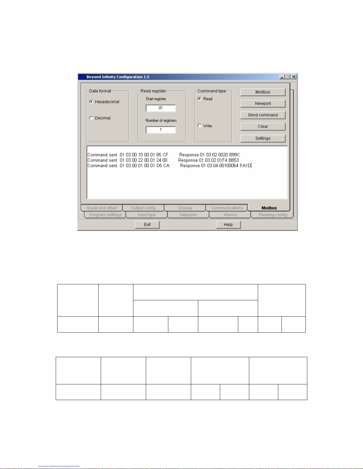
Note: the Universal Input Meters support only Read Single Register, so the
number of registers should always set to 1.
Screenshot for following examples 1- 3:
Figure 8.1: Read Command Samples via Infinity Configuration Software.
Example 1: For one byte data registers: 1
st
data string of Command sent section as
shown on the Figure 8.1:
01 03 0010 0001 85CF : is to read INPUT CONFIGURATION ( INF.CNF and INPUt ).
DEVICE
ADDRESS
FUNCTION
CODE
03 or 04
DATA
STARTING REGISTER NUMBER OF REGISTERS
CRC
01 03 00 10 00 01 85 CF
01 03 02 0000 B844 : 1st Command Response on Figure 8.1 which device
responded to the 1
DEVICE
ADDRESS
01 03 02
st
read command.
FUNCTION
CODE
NUMBER OF
BYTES
VALUES OF
REGISTERS
(1 Byte)
00
(N/A)
20
CRC
B9 9C
For detail description of the VALUES OF THE REGISTER above, refer to Table 10.2 of
Communication Manual.
M - 6
Page 86

Example 2: For 2 bytes data registers: as shown on the Figure 8.1 as 2
the Command sent section:
01 03 0022 0001 2400: is to read the value of Alarm Deadband (AL.db).
nd
data string of
DEVICE
ADDRESS
FUNCTION
CODE
03 or 04
DATA
STARTING REGISTER NUMBER OF REGISTERS
CRC
01 03 00 22 00 01 24 00
01 03 02 01F4 B853 : 2
responded to the 2
nd
nd
Command Response on Figure 8.1 which device
read command.
DEVICE
ADDRESS
FUNCTION
CODE
NUMBER OF
BYTES
01 03 02
VALUES OF
REGISTERS
(2 Bytes)
01 F4
CRC
B8 53
For detail description of the VALUES OF THE REGISTER above, refer to Section 10.37
of Communication Manual.
M - 7
Page 87

Example 3: For 3 bytes data registers: as shown on the Figure 8.1 as 3
rd
data string of
the Command sent section:
01 03 0001 0001 D5CA: is to read Setpoint 1 value (SP1).
DEVICE
ADDRESS
01 03 00 01 00 01 D5 CA
FUNCTION
CODE
03 or 04
DATA
STARTING REGISTER NUMBER OF REGISTERS
CRC
01 03 04 0010 0064 FA1D: 3rd Command Response on Figure 8.1 which device
responded to the 3
rd
read command.
DEVICE
ADDRESS
FUNCTION
CODE
01 03 04
NUMBER
OF BYTES
VALUES OF REGISTERS
(3 Bytes)
00
(N/A)
10 00 64
CRC
FA 1D
NOTE: SetPoints, In/Output Offset and process values (Main, Peak and Valley
Reading Values) must be determined in following manner: (using above example)
Value
Format
Hex. 00
Binary bits
pattern
N/A
Binary N/A
XXXX
(binary bits)
0001 0000 0000 0000 0110 0100
VALUES OF REGISTERS
(3 Hex. Bytes)
10 00 64
XXXX
(binary
bits)
XXXX XXXX
(binary bits)
XXXX XXXX
(binary bits)
X XXX
Setpoints,
In/Output
Offset,
Main/ Peak/
Valley
Readings
Equivalent
Decimal
N/A
0 001
+
DECIMAL
POINT
FFFF. 100 (decimal)
SIGN
Absolute
Value
Absolute Value Absolute Value
+100.
Table 8.1 Format of 3 bytes Data Value Description of SetPoints,
In/Output Offset and process values.
For detail description of How to determine Sign (+ or -) and Decimal Point Position,
refer to Section 10.28 and Table 10.16 of Communication Manual.
M - 8
Page 88
NOTE: Following bits patterns is the format for 3 bytes data registers of
READING SCALE (“RdG.SC”), INPUT SCALE (“INP.SC”), AND
OUTPUT SCALE (“Out.SC”) which are determined differently than the
above example.
Value
Format
Hex.
Pattern
Binary bits
pattern
00
(2 hex.characters)
XXXX
N/A
(binary
bits)
VALUES OF REGISTERS
(3 Hex. Bytes)
hh
(2 hex.characters)
XXXX
(binary bits)
XXXX XXXX
(binary bits)
hh
hh
(2 hex.characters)
XXXX XXXX
(binary bits)
X XXX
Decimal N/A
DECIMAL
POINT
SIGN
Absolute
Value
Absolute Value Absolute Value
Table 8.2 : Format of 3 bytes Data Value Description of all type of Scale Function.
For detail description of How to determine Sign (+ or -), Decimal Point Position and
absolute value, refer to Section 10.34 and Table 10.28 of Communication Manual.
8.2. Write to Single Register (06)
The following command will write a parameter to the single register.
Send / Response Command string format:
DEVICE
ADDRESS
1 BYTE
hh
FUNCTION
CODE
06
1BYTE
06
REGISTER
HB
00
LB
hh
DATA
DATA
VALUE
HB
00
LB
hh
LB
hh
CRC
HB
hh
M - 9
Page 89
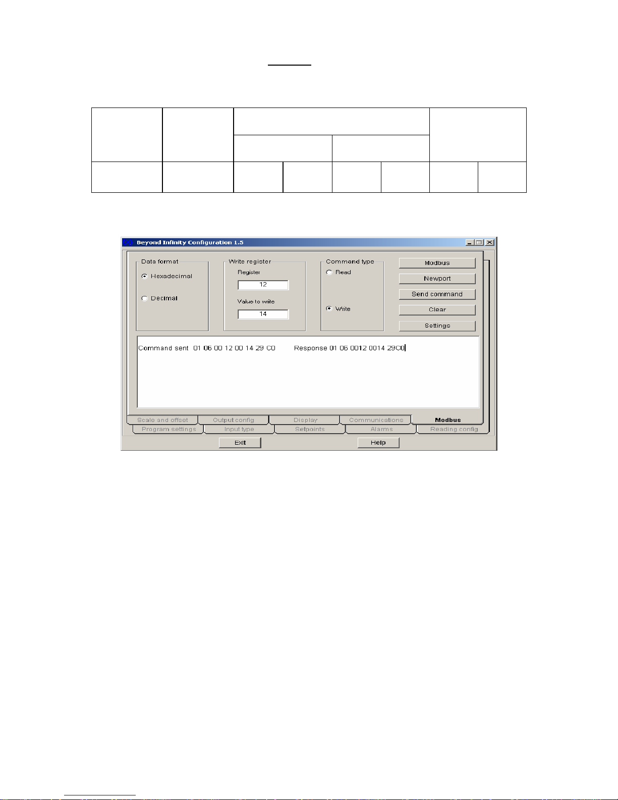
Example 4: For Write Command of one byte
Table 10.1 of Serial Communication Option Operator’s manual to learn how to modify
Reading configuration (RdG.CNF), sent/responded data string as following:
data registers: using example on Section &
DEVICE
ADDRESS
1 BYTE
01
FUNCTION
CODE
06
1BYTE
06
REGISTER
HB
00
Here is the screenshot of the Example 4:
LB
12
DATA
DATA VALUE
(1valid byte)
HB
00
LB
14
LB
29
CRC
HB
C0
Figure 8.2: Write (1 valid Data byte) Command Sample via
Infinity Configuration Software.
M - 10
Page 90
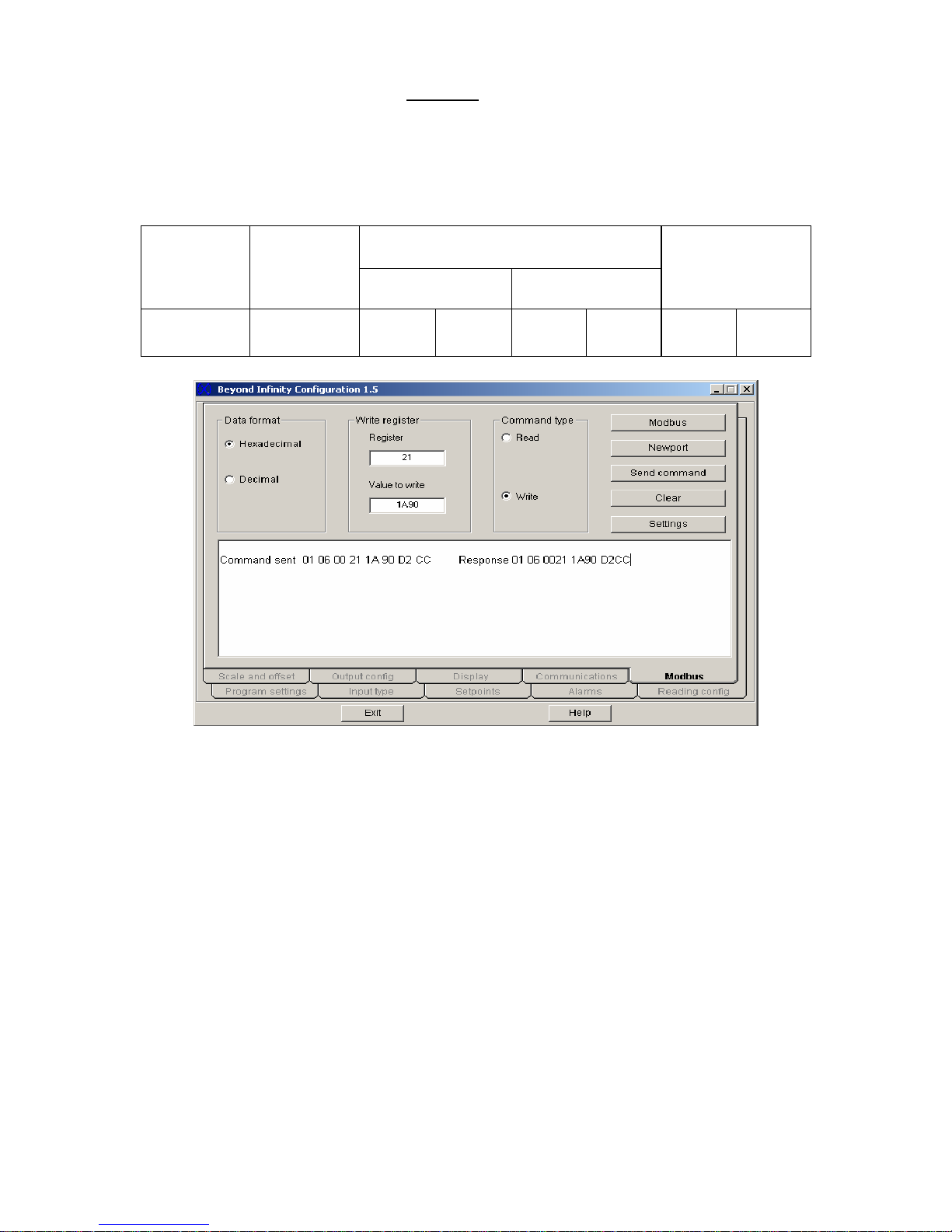
Example 5: For Write Command of two bytes
in this format: Setpoint Deadband (SP.db): Register #21 and Alarm Deadband (AL.db)
Register #22.
Using Example on Section 10.36 of Serial Communication Option Operator’s manual to
write new value of SetPoint Deadband as 6,800 count.
data registers: There are only two registers
DEVICE
ADDRESS
1 BYTE
01
FUNCTION
CODE
06
1BYTE
06
REGISTER
HB
00
LB
21
DATA
DATA VALUE
(2 valid bytes)
HB
1A
LB
90
LB
D2
CRC
HB
C2
Figure 8.3: Write (2 valid Data bytes) Command Sample via
Infinity Configuration Software.
M - 11
Page 91
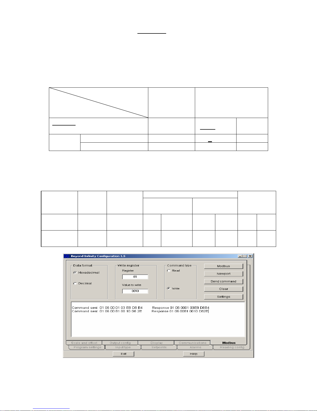
Example 6: For Write Command of three bytes
configure, users must send two write commands to accomplish this task. First one only
change register’s 2 Low Order Bytes (LB)and is just similar to the previous example ,
However second command must write on converted register of original one to write or
modify value of High Order Byte (HB)(as example below illustrate How to set decimal
point and sign of value for detail description of Sign & Decimal Point configuration, refer to
Table 10.26 of Communication).
Following Table illustrates how to convert the register:
data registers: In order to modify or
Format
Register
Register
(Hex. Number)
Register
(Binary Number)
Method: change MSB of
character 0 of Register to 1
Example:
Table 8.3: Conversion Method of 3 Bytes Register for Write Function.
Lets examine how to write SP1 with different values: +1000 and –100.0:
Send / Response Command string format:
Value +1000:
Desired
Values:
+1000
1st command
(for absolute
value)
2nd command
(for Sign &
dec.point)
Reg. of SP1 value 01 0000 0001
Converted SP1 value:
DEVICE
ADDRESS
1 BYTE
01
1 BYTE
01
FUNCTION
CODE
06
1BYTE
06
1BYTE
06
HB
00
HB
00
hh MSB x x x x x x x
81
DATA
REGISTER
LB
01
LB
81
1000 0001
DATA VALUE
(2 bytes used)
HB
03
HB
00
LB
E8
LB
10
LB
D8
LB
D8
CRC
HB
B4
HB
2E
Figure 8.4: Write (3 Data bytes) Commands Sample via
Infinity Configuration Software.
M - 12
Page 92
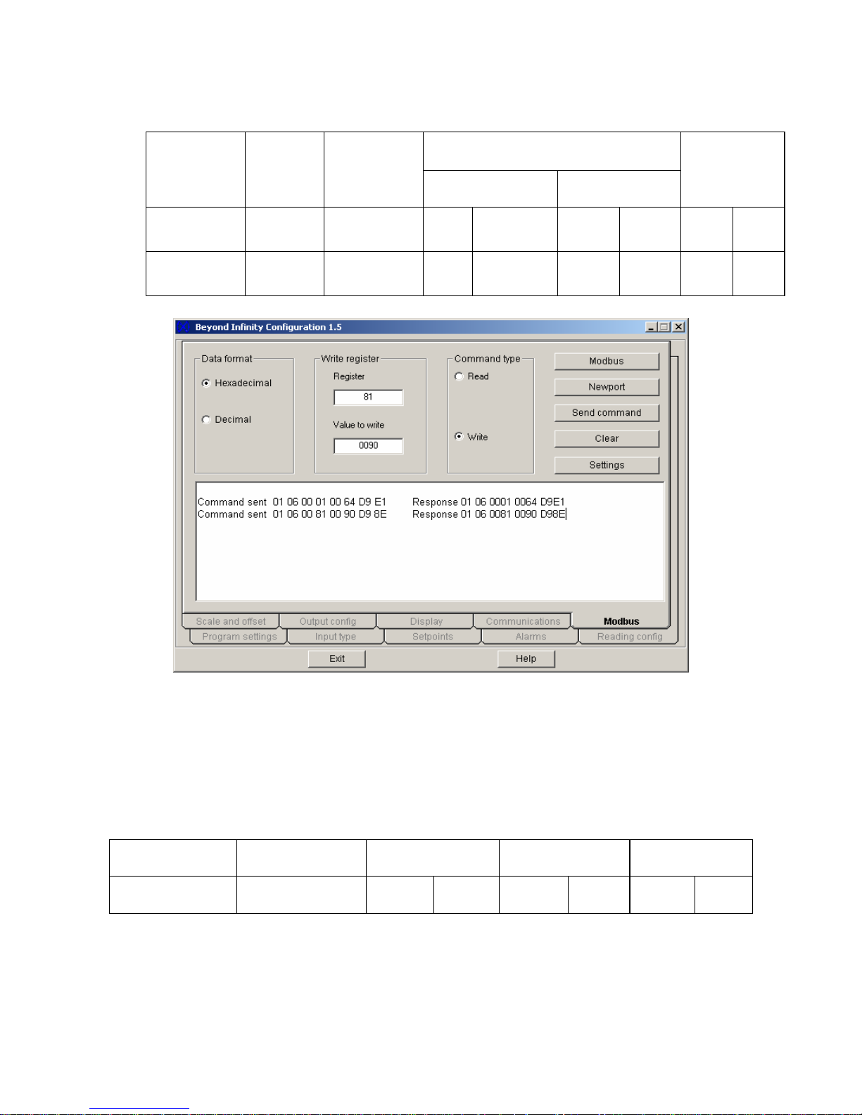
Value -100:
Desired
Values:
-100
1st command
(for absolute
value)
2nd command
(for Sign &
dec. point)
DEVICE
ADDRESS
1 BYTE
01
1 BYTE
01
FUNCTION
CODE
06
1BYTE
06
1BYTE
06
REGISTER
HB
00
HB
00
LB
01
LB
81
DATA
DATA VALUE
(2 bytes used)
HB
00
HB
00
LB
64
LB
90
LB
D8
LB
D8
CRC
HB
B4
HB
2E
Figure 8.5: Write (3 Data bytes) Commands Sample via
Infinity Configuration Software.
8 Diagnostic command.
This command echoes the sent message to indicate that the communication link is
established correctly.
Send to/Return from device:
DEVICE
ADDRESS
1 BYTE
hh
FUNCTION
CODE
1 BYTE
08
DIAGNOSTIC
CODE
HB
00
LB
00
LOOPBACK
DATA
HB
hh
LB
hh
CRC
LB
hh
where:
o Diagnostic Code is two byte code to determine the type of test to be performed.
o Universal Input Meters supported only “00” code which requested slave to echo
sent command back to the master.
M - 13
HB
hh
Page 93

WARRANTY/DISCLAIMER
OMEGA ENGINEERING, INC. warrants this unit to be free of defects in materials and workmanship for a period of one (1) year
from the date of purchase. In addition to OMEGA’s standard warranty period, OMEGA Engineering will extend the warranty period
for four (4) additional years if the warranty card enclosed with each instrument is returned to OMEGA.
If the unit malfunctions, it must be returned to the factory for evaluation. OMEGA’s Customer Service Department will issue an
Authorized Return (AR) number immediately upon phone or written request. Upon examination by OMEGA, if the unit is found
to be defective, it will be repaired or replaced at no charge. OMEGA’s WARRANTY does not apply to defects resulting from any
action of the purchaser, including but not limited to mishandling, improper interfacing, operation outside of design limits, improper
repair, or unauthorized modification. This WARRANTY is VOID if the unit shows evidence of having been tampered with or shows
evidence of having been damaged as a result of excessive corrosion; or current, heat, moisture or vibration; improper
specification; misapplication; misuse or other operating conditions outside of OMEGA’s control. Components which wear are not
warranted, including but not limited to contact points, fuses, and triacs.
OMEGA is pleased to offer suggestions on the use of its various products. However, OMEGA neither assumes
responsibility for any omissions or errors nor assumes liability for any damages that result from the use of its products
in accordance with information provided by OMEGA, either verbal or written. OMEGA warrants only that the parts
manufactured by it will be as specified and free of defects. OMEGA MAKES NO OTHER WARRANTIES OR
REPRESENTATIONS OF ANY KIND WHATSOEVER, EXPRESS OR IMPLIED, EXCEPT THAT OF TITLE, AND ALL IMPLIED
WARRANTIES INCLUDING ANY WARRANTY OF MERCHANTABILITY AND FITNESS FOR A PARTICULAR PURPOSE ARE
HEREBY DISCLAIMED. LIMITATION OF LIABILITY: The remedies of purchaser set forth herein are exclusive, and the
total liability of OMEGA with respect to this order, whether based on contract, warranty, negligence, indemnification,
strict liability or otherwise, shall not exceed the purchase price of the component upon which liability is based. In no
event shall OMEGA be liable for consequential, incidental or special damages.
CONDITIONS: Equipment sold by OMEGA is not intended to be used, nor shall it be used: (1) as a “Basic Component”
under 10 CFR 21 (NRC), used in or with any nuclear installation or activity; or (2) in medical applications or used on
humans. Should any Product(s) be used in or with any nuclear installation or activity, medical application, used on humans,
or misused in any way, OMEGA assumes no responsibility as set forth in our basic WARRANTY/DISCLAIMER language,
and, additionally, purchaser will indemnify OMEGA and hold OMEGA harmless from any liability or damage whatsoever
arising out of the use of the Product(s) in such a manner.
RETURN REQUESTS/INQUIRIES
Direct all warranty and repair requests/inquiries to the OMEGA Customer Service Department. BEFORE RETURNING
ANY PRODUCT(S) TO OMEGA, PURCHASER MUST OBTAIN AN AUTHORIZED RETURN (AR) NUMBER FROM
OMEGA’S CUSTOMER SERVICE DEPARTMENT (IN ORDER TO AVOID PROCESSING DELAYS). The assigned AR
number should then be marked on the outside of the return package and on any correspondence.
The purchaser is responsible for shipping charges, freight, insurance and proper packaging to prevent breakage in
transit.
FOR WARRANTY RETURNS, please have the following
information available BEFORE contacting OMEGA:
1. Purchase Order number under which the product was
PURCHASED,
2. Model and serial number of the product under warranty,
and
3. Repair instructions and/or specific problems relative to
the product.
FOR NON-WARRANTY REPAIRS,
consult OMEGA for current
repair charges. Have the following information available
BEFORE contacting OMEGA:
1. Purchase Order number to cover the COST of the repair,
2. Model and serial number of product, and
3. Repair instructions and/or specific problems relative to the
product.
OMEGA’s policy is to make running changes, not model changes, whenever an improvement is possible. This affords our
customers the latest in technology and engineering.
© Copyright 2005 OMEGA ENGINEERING, INC. All rights reserved. This document may not be copied, photocopied,
reproduced, translated, or reduced to any electronic medium or machine-readable form, in whole or in part, without the prior written
consent of OMEGA ENGINEERING, INC.
TRADEMARK NOTICE:
®
, omega.com
®
and are Trademarks of OMEGA ENGINEERING, INC.
PATENT NOTICE: This product is covered by one or more of the following patents: U.S. Pat. No. Des. 336,895; 5,274,577;
6,243,021 / CANADA 2052599; 2052600 / ITALY 1249456; 1250938 / FRANCE BREVET No. 91 12756 / SPAIN 2039150;
2048066 / UK PATENT No. GB2 249 837; GB2 248 954 / GERMANY DE 41 34398 C2. The “Meter Bezel Design” is a Trademark
of NEWPORT Electronics, Inc. Used under License. Other US and International Patents pending or applied for.
®
Page 94

M2546/1205
Where Do I Find Everything I Need for
Process Measurement and Control?
OMEGA…Of Course!
Shop on line at www.omega.com
TEMPERATURE
Thermocouple, RTD & Thermistor Probes, Connectors, Panels & Assemblies
Wire: Thermocouple, RTD & Thermistor
Calibrators & Ice Point References
Recorders, Controllers & Process Monitors
Infrared Pyrometers
PRESSURE, STRAIN AND FORCE
Transducers & Strain Gauges
Load Cells & Pressure Gauges
Displacement Transducers
Instrumentation & Accessories
FLOW/LEVEL
Rotameters, Gas Mass Flowmeters & Flow Computers
Air Velocity Indicators
Turbine/Paddlewheel Systems
Totalizers & Batch Controllers
pH/CONDUCTIVITY
pH Electrodes, Testers & Accessories
Benchtop/Laboratory Meters
Controllers, Calibrators, Simulators & Pumps
Industrial pH & Conductivity Equipment
DATA ACQUISITION
Data Acquisition & Engineering Software
Communications-Based Acquisition Systems
Plug-in Cards for Apple, IBM & Compatibles
Datalogging Systems
Recorders, Printers & Plotters
HEATERS
Heating Cable
Cartridge & Strip Heaters
Immersion & Band Heaters
Flexible Heaters
Laboratory Heaters
ENVIRONMENTAL
MONITORING AND CONTROL
Metering & Control Instrumentation
Refractometers
Pumps & Tubing
Air, Soil & Water Monitors
Industrial Water & Wastewater Treatment
pH, Conductivity & Dissolved Oxygen Instruments
 Loading...