

Page 1
Programmable
Dual Channel Monitor
DP3300 Series User's Manual
OMEGA ENGINEERING, INC.,
ONE OMEGA DRIVE, STAMFORD, CT 06907
Page 2

DP3300 Series User’s Manual
SPECIFICATIONS:............................................................................................................................................................................3
DESCRIPTION:..................................................................................................................................................................................4
SAVING PROGRAMMED PARAMETER:......................................................................................................................................4
Table 1. How to Display Parameters..............................................................................................................................................5
PEAKS:...............................................................................................................................................................................................5
DISPLAYING PEAKS...................................................................................................................................................................5
RESETTING PEAKS .....................................................................................................................................................................6
RATE:.................................................................................................................................................................................................6
MODES OF OPERATION FOR PULSE CHANNEL:......................................................................................................................6
RATE MONITOR:..........................................................................................................................................................................6
RPM MONITOR.............................................................................................................................................................................6
FREQUENCY MONITOR:............................................................................................................................................................7
COUNTER......................................................................................................................................................................................7
MODES OF OPERATION FOR COUNTER:....................................................................................................................................8
COUNT UP CONFIGURATION:..................................................................................................................................................8
MODE 0: (Count up with manual reset to zero)........................................................................................................................8
MODE 1: (Count up to Preset with auto reset to zero)..............................................................................................................8
MODE 2: (Count up to Preset with auto Zero after delay)........................................................................................................8
COUNT DOWN CONFIGURATION............................................................................................................................................8
MODE 3: (Count down to zero with manual preset)..................................................................................................................8
MODE 4: (Count down to zero with auto preset).......................................................................................................................8
MODE 5: (Count down to zero with auto preset after delay)......................................................................................................8
RESETTING COUNT:.......................................................................................................................................................................9
RELAY DELAY PERIOD: ............................................................................................................ ....................................................9
TOTALIZER:......................................................................................................................................................................................9
BATCH COUNT: ...............................................................................................................................................................................9
SCALING:..........................................................................................................................................................................................9
TIME:..................................................................................................................................................................................................9
SETUP: .............................................................................................................................................................................................10
EXITING SETUP:............................................................................................................................................................................10
CHANNEL CONFIGURATION......................................................................................................................................................10
‘Input Type’ Setup ....................................................................................................................................................................10
‘Channel ON/OFF’ Setup..........................................................................................................................................................11
Setup for degrees Centigrade or Fahrenheit..................................................................................................................................11
‘Decimal Point Position’ Setup.................................................................................................................................................11
‘High Scale’ Setup....................................................................................................................................................................11
‘Low Scale’ Setup.....................................................................................................................................................................11
‘Offset’ Setup............................................................................................................................................................................11
‘Tare’ Setup...............................................................................................................................................................................12
‘Limits’ Setup ...........................................................................................................................................................................12
‘Deadband’ Setup......................................................................................................................................................................12
‘Relay Latched/Non-Latched Mode’ Setup...............................................................................................................................12
‘Relay Normally Open/Closed’ Setup.......................................................................................................................................12
‘Engineering Units’ Setup.........................................................................................................................................................13
‘Rate Time Base’ Setup.............................................................................................................................................................13
Input Signal type selection:...........................................................................................................................................................13
SYSTEM CONFIGURATION:........................................................................................................................................................13
Display Options.............................................................................................................................................................................14
‘Display Time’ Setup....................................................................................................................................................................14
Audio Alarm ON/OFF ..................................................................................................................................................................14
Cold Junction Setting....................................................................................................................................................................14
Calibration Mode ..........................................................................................................................................................................14
Thermocouple Calibration Procedure ...........................................................................................................................................14
Input Range Setup (for current and voltage):................................................................................................................................15
Voltage Range Setup (0-5vdc, 0-10vdc)...................................................................................................................................15
Voltage Range Setup (for millivolt inputs)...............................................................................................................................15
Current Range Setup.................................................................................................................................................................15
Correct Range Settings..............................................................................................................................................................15
Setup Examples.............................................................................................................................................................................15
Example #1: Use of the OFFSET Parameter.............................................................................................................................15
Example #2: Use of the LOW SCALE Parameter....................................................................................................................15
SETUP FOR A PULSE CHANNEL:................................................................................................................................................18
Page1
Page 3

DP3300 Series User’s Manual
Turning a Channel ON or OFF .....................................................................................................................................................18
MODES OF OPERATION FOR A PULSE INPUT CHANNEL:................................................................................................18
SETUP FOR COUNTER:.............................................................................................................................................................18
SETUP FOR HIGH AND LOW FREQUENCY MONITOR:...................................................................................... ................19
SETUP FOR RATE MONITOR:..................................................................................................................................................20
SETUP FOR RPM MONITOR:....................................................................................................................................................20
ALARM OUTPUTS:........................................................................................................................................................................21
Status:............................................................................................................................................................................................21
Resetting: ......................................................................................................................................................................................21
Open Collector (solid state) output Option:..................................................................................................................................22
Figure 1. Open Collector Hookup Example.............................................................................................................................22
Electro-Mechanical Relay Option:...............................................................................................................................................22
Figure 2. Electro-mechanical Relays Hookup Example............................................................................................................22
POWER.............................................................................................................................................................................................22
FIG. 3: Power, Input/Output connections & rear view of the instrument...........................................................................23
INPUT/OUTPUT CONNECTOR PIN ASSIGNMENTS.............................................................................................................23
MOUNTING.....................................................................................................................................................................................24
Figure 4. Panel Cutout Dimensions...............................................................................................................................................24
WARRANTY/DISCLAIMER..........................................................................................................................................................25
Page2
Page 4

DP3300 Series User’s Manual
SPECIFICATIONS:
(Typical @ 25C and rated supply voltage unless otherwise specified)
STANDARD INPUTS
• * 4-20ma 10-50ma 0-5Vdc 0-10Vdc
• Thermocouple inputs: J,K,T,E,R,S,B
• Cold junction compensation error: +/- 1C (10C to 40C)
• Open input indication: HELP displayed
• Temperature displayable in Degrees C or F
• Non standard inputs availab le --- consult factory.
ANALOG TO DIGITAL CONVERSION
• 4-1/2 Digit (20,000) Count) A/D Converter
• Dual slope integrating converter with 7 conversions /sec. (typical) rate.
SCAN RATE
• Fixed: two channels per second
DISPLAY
• Red seven segment displays--0.39" (10mm) digit height
• Over range indication: HELP
• Display test: Briefly displays 8.8.8.8.8.8.8 on power up.
• Seven digit display
SCALE/OFFSET
• Scale programmable from 1-30000 units
• Offset programmable from 0-99.99 MA (For MA Input)
• Offset programmable from 0-9.999 MV (For Voltage Input)
RELIABILITY/ACCURACY
• Calibration: NIST traceable (for thermocouples)
• Temperature resolution: 1C/1F, 0.1% of Full Scale
• Warranty: 1 Year
• Recalibration recommended at 12 month interval
POWER REQUIREMENT
• * 120Vac --- 60 HZ (Standard)
• * 240Vac --- 50 HZ (optional)
• * 8Vdc --- 12Vdc (optional)
OUTPUT (optional)
• Open collector outputs – 6 open collector outputs, maximum sink capability of 50ma per output
• Relays: Single pole single throw, 1 Amp @ 28Vdc or 0.5 Amp @ 120Vac resistive
• Output termination: Euro-style plugable connector
DECIMAL POINT:
• Programmable: None, 10
COUNT/RATE/RPM/FREQUENCY:
• Count Range : 1 – 9999999 Rate Range: 0 – 9999999 Frequency Range: 2.00 to 1000000 RPM Range: 0 - 9999999
• Scaler 0.00000 to 99.99999
• Division factor: 0 to 65000
• Rate Time Base: Programmable 1.000 Seconds to 9999.999 Seconds
th
position, 100th position, 1000th position
Page3
Page 5

DP3300 Series User’s Manual
DESCRIPTION:
A highly versatile series, DP3300 offers a unique combination of two analog channels or two pulse input channels or a
combination of pulse (square wave) on one channel and an analog signal on the other. This feature allows it to be used as
counter, rate, RPM or a frequency monitor along with displaying an analog signal such as 4-20ma loop current, voltage or
millivolts or a temperature signal from thermocouples, RTDS etc. For example, flow and temperature or flow and pressure can
easily be monitored in a single unit.
On the analog channel, signals from thermocouples, RTDS or thermistors are linearized and displayed in degrees Centigrade or
Fahrenheit. Voltage and milliamp signals (4-20ma etc.) are displayed in engineering units that correspond to the process being
monitored. Scaling is accomplished through front keys and does not require any tedious formulas.
The Pulse (or square wave input) channel functions like four monitors in one. It can be programmed as an up/down counter, rate,
rpm or frequency monitor. In counter mode, the channel can count up or down to a maximum count of 9,999,999 and also offers
three presets along with built in delay timers. As a rate indicator, it offers a programmable time base from 1.000 to 9999.999
seconds.
In RPM mode, the channel counts incoming pulses and displays the data as revolutions per minute. In frequency mode, an internal
crystal reference is used to indicate the frequency of incoming pulses (low frequency mode only). Measured frequency range is
from 1Hz to 1 megahertz. Two modes of operation are supported:
1. High frequency mode (resolution = 1Hz)
2. Low frequency mode ( resolution = 0.01 Hz)
NOTE: Check model number for the t ype of input and display units ---- thermocouples, 4-20ma, 0-5 Vdc, or 0-1 0Vdc
etc...
DP3300-TC
DP3300-TH
DP3300-RTD
DP3300-R
DP3300-S
DP3300-B
DP3300-MV
J,K,T,E Thermocouple, 4-20ma, 0-10vdc
& 0-5vdc pulse
Thermistor (400 Series) , 4-20ma, 0-10vdc and
0-5vdc pulse
100 Ohm RTD , 4-20ma, 0-10vdc and
0-5vdc pulse
'R' Thermocouple, 4-20ma, 0-10vdc and
0-5vdc pulse
'S' Thermocouple , 4-20ma, 0-10vdc and
0-5vdc pulse
'B' Thermocouple , 4-20ma, 0-10vdc and
0-5vdc pulse
100Millivolt , 4-20ma, 0-10vdc and
0-5vdc pulse
OPTIONS (Add to Model No)
SUFFIX DESCRIPTION
-1 240vac Power
-2 15vdc Power
-3 4 Relay Outputs
-4 4 Open collector outputs
SAVING PROGRAMMED PARAMETER:
DP3300 saves all the programmed parameters in an EEPROM (electrically erasable programmable read only memory).
An EEPROM stores the programmed parameters even when the power is removed from the unit. However, it is important to note
that if the parameters are being changed during setup, they must be saved in the EEPROM by pressing and holding the RESET
key till the display reads 'SAVING' (also described under SETUP). If the parameters are NOT
from the unit, any newly changed values will be lost (the unit will, however, maintain the old values).
Page4
saved and the power is removed
Page 6

DP3300 Series User’s Manual
) Hold
sca
push the
SCN/
ce.
Table 1. How to Display Parameters
TO DISPLAY PERFORM FOLLO WING STEPS
1) Channel 1’s Process value a) Push CH SEL key once.
2) Channel 2's Process a) Push CH SEL key twice. First push selects channel 1 and the
Value second push will select and display channel 2's process reading.
3) Channel's high peak a) Select channel whose hi gh peak is desired (push CH SEL key)
b) Push HI/LO key once
4) Channel's low peak a) Select channel whose low peak is desired (push CH SEL key)
b) Push HI/LO key twice --- 1st push displays high peak,
2nd push , low peak.
5) Rate a) Select channel whose rate is desired (push CH SEL key)
b) Push DATA key once.
6) Channel Differential a) Select a channel by pushing CH SEL key ONCE
b) Push DATA key twice -- 1st push displays rate,
2nd push: Channel Differential
7) TOTAL a) Select a channel by pushing CH SEL key twice
b) Push DATA key SIX times till TOTAL displays in the window
The sequence is: Rate, Channel differential, Limit1, Limit2, Limit3, Total
8) BATCH a) Select a channel by pushing CH SEL key twice
b) Push DATA key SEVEN times till bATCH displays in the window,
The sequence is: Rate, Channel differential, Limit1, Limit2, Limit3, Total, Batch
9) LIMITS a) Push CH SEL key to select desired channel
b) Push DATA key THREE times to display channel's limit number 1
c) Each additional push after that will display limit 2 & limit 3
10) Elapsed time a) Push TIME key.
11 Scan a) If the unit is holding, push the SCN/HLD key once.
12
a) If the unit is
nning,
HLD key on
PEAKS:
A very useful function on the system is tracking the highest (peak) and the lowest (valley ) point attained by each channel. This is
particularly helpful if an operation is not being constantly watched or is left unattended e.g. overnight.
DISPLAYING PEAKS
The first step in displaying peaks is to select the channel whose peaks are desired. This is done by pushing the 'CH. SEL' key.
Once the desired channel has been selected, push the 'HI/LO' key. Pushing it once will show the high peak attained by the
selected channel. Pushing it a second time will indicate the low process value (NOTE: The second push, to display valley, must
be initiated before the display reverts to normal display mode). Before displaying high peak the display will read 'CHx HI'
(x=channel #). Similarly, for low peak the display will indicate 'CHx LO' (x=channel #) b efore showing the value.
If an attempt is made to display the high or low peak of a channel which has been turned off (in CH Setup), the display will read
'CHx OFF' (x=channel #) to indicate the channel status.
Page5
Page 7

DP3300 Series User’s Manual
RESETTING PEAKS
Peaks can be reset to current process value e.g. if channel 1 is reading 200 C, its peaks can be reset to 200. This will allow
tracking from the current process reading. To reset high peak, first select the channel whose peak is desired to be reset (by
pushing the ‘CH. SEL’ key). Once the channel has been selected, push the ‘HI/LO’ key and keep it pushed. The display will
read 'CHx HI' (x=channel #) following which the value of high peak will be displayed. With the HI/LO key still pushed, go on
to push the RESET key. The display will read 'RESEt' and the unit will then take the present value of process on that channel
and enter it as the new high peak. To reset low peak, release HI/LO key (from high peak display mode) and push it again
immediately -- and keep it pushed. The display will read 'CHx LO' and then the value of channel's low peak. With the HI/LO
key still pushed, press the RESET key. The display will read 'RESEt' and the unit will enter the present process value as
channel's new low peak.
RATE:
DP3300 tracks the rate of process change per programmed time base for each channel. This RATE is displayed by first pushing
the CH. SEL key to select the channel whose rate is desired and then pushing DATA key once. The display will briefly read
'rAtE' and then show the monitored rate for that channel.
MODES OF OPERATION FOR PULSE CHANNEL:
RATE MONITOR:
As a rate indicator, DP3300 series features crystal controlled accuracy and provides the flexibility of a programmable time base
for sampling. The time base can be set from 1.000 seconds through 9999.999 seconds in increment of 0.001 second and is done
during SETUP (look under SET-UP). Additionally, a division or scaler factor can also be programmed that will divide or scale the
incoming pulses. For a quicker update of rates , a scaler factor can be programmed (when a channel is programmed for a rate
mode). For example, if rate /minute is desired, then setting the time base to 1.000 and scaler to sixty, will give you rate/minute.
This rate, however, will be updated every one second. It may be noted that rate calculated this way may loose some accuracy.
Additionally, the unit shows the rate, based on the programmed time base in all the system modes i.e. frequency, counter and
RPM. This can be displayed by first selecting the desired channel (by pushing CH SEL key) and then pushing the DATA key.
(NOTE: In the RPM mode, the rate time base must be smaller than the selected filter value. If not, the system will
automatically consider the filter value as the time base for rate calculation. Also, a difference of 0.500 is recommended
between the filter and time base).
There are three rate based limits (two withoutputs, 1 audio/visual) that can be set anywhere from 1-9,999,999. These limits can be
configured to reset automatically when the rate falls below the set limit or alternately reset manually. This is done by going into
the setup mode and selecting the proper configuration (look under SETUP).
RPM MONITOR
In RPM mode, the system will accept 0-5V square wave or pulse input from a sensor and show revolutions per minute. The input
has a schmitt trigger so as to accept any kind of square wave or pulses, as long as the high and low specifications are met.
Also a filter function is provided in the RPM mode which allows to smooth out rapidly changing RPM. On the contrary, if it is
desired to see the variation in the RPM, then this feature alsocomes in handy. Select a low filter value to see variations in RPM
and a higher value for a more stable display. Selectable filter values are 1,2,4,6,10,15,20,30 and 6 0 and the selection is done in
SETUP mode.
Three RPM based limits (two with outputs, 1 audio/visual) are provided for each channel that can be set to activate internal relays
when a preset limit is exceeded. The ON/OFF status of these relays is indicated on the front panel by LEDs.
There are two modes of resetting the limits. First is automatic mode in which the limits reset automatically as soon as RPM falls
Page6
Page 8

DP3300 Series User’s Manual
below the limit (minus the relay) deadband. The second mode is manual reset. Once the limits are energized, they will stay
energized until manually reset.
(NOTE: In the RPM mode, the rate time base must be smaller than the selected filter value. If not, the system will
automatically consider the filter value as the time base for rate calculation. Also, a difference of 0.500 is recommended
between the filter and time base).
FREQUENCY MONITOR:
DP3300 monitor can also be programmed as a frequency monitor. In this mode the unit will display incoming frequency with a
crystal based reference. Input signal is used for gating one time period. An internal counter counts the clocks from a crystal based
oscillator and uses that to determine the frequency of incoming signal. Frequency range is from 5.00HZ to 1,000,000 HZ.
There are two frequency modes in which the system operates. Low frequency and high frequency. These modes are selected
during SETUP. In low frequency mode, the unit will show frequency in 100th of a hertz and the range is from 2.00 HZ to 500.00
HZ. In high frequency mode, the system displays the frequency in unit steps. The range is from 1 HZ to 1,000,000HZ.
During frequenc y mode, indicated rate is same as the frequency. Total and batch count is not updated during this mode. H igh and
low peaks are captured and can be displayed by pushing the HI/LO key.
Three Frequency based limits (two with outputs, 1 audio/visual) per channel are provided which activate when preset limit is
exceeded. The status of these limits is indicated on the front panel by LEDs.
There are two modes of resetting the limits. First is the automatic mode in which the limits reset automatically as soon as the
frequency falls below the limit minus the relay deadband. The second mode is manual reset. Once the relays are energized, they
will stay energized until manually reset.
NOTE: Channel 2 can be prog r ammed for low frequency mode, only if Channel 1 input is not configured for pulse. If
Channel one is configured for pulse input, Channel 2 does not allow low frequency config uration during setup and the low
frequency step is automatically skipped. Also, if Channel 2
setup as Analog Channel) and Channel 1
from low frequency to high frequency mode. Under this condition, limits must be reconfigured for proper value with no
decimal point on channel 2.
is switched from Analog to Pulse input, channel 2 will be a ut omatically switched
is configured for low frequency (e.g. with Channel 1 being
COUNTER
In counter mode, the system can be programmed to either count up or count down in six different modes. The limit relays can be
programmed to reset manually or automatically. Also, the delay time on automatic reset of the relays is programmable.
For scaling, the unit provides the convenience of a scaler and a division factor. The scaler can be programmed from 0.00000 to
99.99999, in increments of 0.00001. Scaler is a number with which the input count is multiplied. For Example a flow meter that
puts out one pulse for every 0.00024 gallons, would require a scaler of 0.00024. On a pulse count of 10000, the display will read
2.4 (10000 x 0.00024 = 2.4). Scaler is disabled if its value is set to 0.00000. Similarly, the division factor works on incoming
pulses and divides them with the programmed factor.
NOTE: Division factor is disabled
Various operating modes of the counter are explained below:
if a scaler value greater then 0.00000 is programmed.
Page7
Page 9

DP3300 Series User’s Manual
MODES OF OPERATION FOR COUNTER:
COUNT UP CONFIGURATION:
MODE 0: (Count up with manual reset to zero)
In this mode the system counts up from zero. Preset limits energize when the count reaches presets limit values. The unit
will continue counting up until manually reset. To reset the count manually, first select a channel by pushing CH SEL
key and ,while keeping CH SEL key pushed
and then the reset value of zero will be displayed. On resetting to zero, the outputs will automatically de-energize and
this will be indicated by the LED'S for the respective outputs turning off on the front panel.
MODE 1: (Count up to Preset with auto reset to zero)
In this mode the counter counts up to a preprogrammed preset value (look under SETUP). On reaching preset the counter
automatically resets to zero and starts the up count again. The count can be reset manually before it reaches preset. To
reset the count manually, first select a channel by pushing CH SEL key and ,while keeping the CH SEL key pushe d
simultaneously push the RESET key. The display will read 'RESET' and then the reset value of zero will be displayed.
Preset limits energize when the count reaches limit values.
MODE 2: (Count up to Preset with auto Zero after delay)
In this mode the counter counts up from zero to a preset value. Preset limits energize when the count reaches limit
values. On reaching PRESET, the delay period starts. After the delay period is over, the count is automatically zeroed,
the limits, if energized (and in non-latch mode), are reset and the count up starts again. The delay period is programmed
in SET - UP mode.
For example, if PRESET is set to 9000 counts and the delay period is programmed for 10 seconds, then when the counter
reaches 9000, the delay period will start and after 10 seconds of reacing 9000 count, the count will be reset to zero.
, simultaneously push the RESET key . The display will read 'RESET'
,
COUNT DOWN CONFIGURATION
MODE 3: (Count down to zero with manual preset)
In this mode the counter counts down from a preset number (preset number is programmed during SETUP). On
reaching zero the counter will not decrement further until manually preset. To preset the counter value manually, push
CH SEL key to select a channel. While keeping CH SEL key pushed, go on to push the RESET key simultaneously.
The display will read 'RESET' and then the displayed value will be reset to zero. Count down will start immediately
thereafter.
When count goes down to a limit value the respective output is energized. The output will stay energized until the count
is preset as explained above.
MODE 4: (Count down to zero with auto preset)
In this mode the counter counts down from a pre-programmed preset value (look under SETUP). When count goes
down to limit value, the respective output gets energized. The display in the meantime will keep counting down. When
it reaches zero, it will automatically preset itself to the programmed preset value.
NOTE: i) Time delay in modes 2 and 5 must be less than the time required to count from zero to
preset or preset to zero.
MODE 5: (Count down to zero with auto preset after delay)
In this mode the counter counts down from a Preset value. Preset limits energize when the count reaches limit values. On
reaching zero, the delay period starts. After the delay period is over, the count is automatically preset, the limits, if
energized (and in non-latch mode), are reset and the count down starts again. The delay period is programmed in SET UP mode.
Page8
Page 10

DP3300 Series User’s Manual
RESETTING COUNT:
The COUNT shown for each channel can be reset to zero or preset for a count down (depending on counter mode) at any time. To
reset the count manually, first select a channel by pushing CH SEL key and ,while keeping the CH SEL key pushed
RESET key simultaneously. The display will read 'RESET' and then the reset value of zero will be displayed. If the counter is
set for count down mode, then the display will preset to the value that was programmed during SETUP.
, push the
RELAY DELAY PERIOD:
Relay delay period in counter modes 2 and 5 is programmable from 1 to 9999999 seconds (look under SETUP). Delay period is
the time for which the output stays in its current state on reaching zeroor preset. Following the end of delay period, the output is
either reset or preset (depending on the counter type seleted).
TOTALIZER:
DP3300 series keeps track of total in counter, RPM and rate mode and can be displayed by pushing the DATA key.
In rate mode, if the displayed rate is 500 units per minute, then over a period of half an hour the total would be 15000 (500 x 30 =
15000). Similarly in RPM mode the TOTAL is the accumulated revolutions over the time period the unit has been working.
In counter mode, the unit indicates the total count. This is irrespective of preset value i.e. if the preset is 5000 and the counter is in
count - up mode, then after the unit has gone through ten preset cycles, the display will indicate a total of 50,000 (5000 x 10 =
50,000). If in count down mode, the total represents the accumulated down counts.
BATCH COUNT:
DP3300 series also offers batching capability in counter mode. One batch constitutes of counting up or down (to preset or zero,
respectively) to or from the preprogrammed PRESET value e.g. if PRESET is set to 5000 (and the channel is in counter mode 3)
then each time the count goes up to 5000, it will reset to zero and start counting up again. This will constitute one batch.
To view the number of batches processed, first select a channel (by pushing CH SEL key) and then successively push DATA key
till BATCH shows on the display. To reset batch count, bring up the batch count on the display and while still holding in the
DATA key, simultaneously push the RESET key. The display will show 'RESET' followed by reseting of batch count.
SCALING:
Scaling is used for multiplying or dividing incoming pulses by a number. It is achieved by programming Scaler value or division
factor during SETUP. This feature is useful if each revolution of a shaft produces more then one pulse, e.g. if a shaft gives 100
pulses per revolution then programming the division factor equal to 100 will give the actual RPM of the shaft. This can also be
used in cases where a count is required on boxes with each box containing a certain number of parts, e.g. if it is required to obtain
the count on cartons containing soft-drink bottles with each carton containing 50 bottles, the scaler will be set to 50. Similarly
scaling can be use d to measure length o r flow of liquids.
Scaler can be programmed from 0.00000 to 99.99999, in increments of 0.00001. Scaler is a number with which the input count is
multiplied. For Example, a flow meter that puts out one pulse every 0.00024 gallons, would require a scaler of 0.00024. On a
pulse count of 10000 (and decimal point programmed in 10
is disabled if its value is set to 0.00000.
The difference between division factor and scaler is that division factor is in whole number where as scaler can be programmed in
increments of 10,000th of a unit. Also, the maximum scaler value that can be entered is 99.99999. However, SCALER should be
limited so that the display would not go into over range condition. For Example, if the SCALER is set to 65.12345 and the pulse
count goes to 1000000, the overall number becomes 65,123,450. This number is beyond the display capability of the unit).
th
position), the display will read 2.4 (10000 x 0.00024 = 2.4). Scaler
TIME:
The system keeps track of the process run time in Hours, minutes and seconds. To display the elapsed time since the system was
turned on or the time was last reset, push the TIME key. The display will first read "ELPSD T" ( for elapsed time) followed by
Page9
Page 11

DP3300 Series User’s Manual
the indication of the elapsed time. Maximum time indicated is 999.59.59 hours.
To reset the timing and start it all over again, first push the TIME key and while keeping it pushed,
time will reset and start over from 000.00.00 hours.
press the RESET key. The
SETUP:
Setup mode provides a means to customize the monitor to suit a particular application. It allows programming such parameters as
temperature units, limits, display mode, relay deadband, etc.
SETUP mode has 2 sections:
a) the SYS setup section to set system parameters
b) the CH setup section to set channel parameters for each channel.
To get into SETUP mode, push the SETUP key twice. The first push displays elapsed time and the second push brings the unit
into the SETUP mode. SETUP mode is indicated by 'SETUP' in the display window (the SETUP LED indicator will also be
illuminated) followed by 'ENtR PC' (for ENteR Pass-Code). The pass-code feature has been provided to keep unauthorized
personnel from changing any parameters. Each of the five keys on the front panel are labeled with a number in the lower right
corner. The pass-code is a four digit combination of these numbers. Enter the pass-code when the displays reads 'ENTR PC' .
For DP3300 units, the PASS-CODE # is 3254.
Three attempts at entering the correct pass-code are allowed. 'HELP' shows up in the display window if the attempted pass-code
is wrong. If a person fails in three attempts the system will go back to normal display mode. To make another attempt at this
point one has to get into SETUP mode again.
Three keys are used during setup --- SETUP, < NEXT >, and ^v. If, at any point during SETUP, it is desired to get out of
SETUP, push and hold the RESET key until the display reads 'SAVING'. The SETUP key takes you from one parameter to the
next. For Example, if you are setting up Channel O N/OFF, then after getting t he desired value p ush SETUP key to setup for
Degrees C/F. The <NEXT> and ^v keys are used for programming the values of parameters such as limits, setpoints, etc.
EXITING SETUP:
To exit from any point during SETUP procedure or to save the newly made changes, simply press and hold the RESET key until
the display shows 'SAVING'. This indicates that the unchanged and the newly made changes are being saved in the EEPROM for
permanent storage.
Once the correct pass-code has been entered, the display shows 'SYS CH', with CH blinking. At this point the operator may
choose between making channe l settings (CH), or system settings (SYS). Use ^v key to toggle between CH and SYS modes.
When the desired mode is blinking, press the SETUP key to begin setup of the parameters for that mode.
CHANNEL CONFIGURATION
After entering the correct pass-code and selecting the blinking 'CH' (ref. SETUP section), the display shows 'SLCt CH' (for
"Select Channel"). Use ^v key to display the desired channel. The selected channel will be displayed in the format 'CHANEL x'
(where x=channel#). Once the desired channel # is displayed, push SETUP key to go on to setup parameters for the displayed
channel #.
‘Input Type’ Setup
The display will briefly show 'IP TYPE' (for "Input type") after which current input type for the channel will be displayed.
Various inputs are: J T/C, CR.AL T/C (Chromel Alumel, type K T/C), T T/C, E T/C, CURRENT, VOLTAGE or PULSE
(Refer to model number on the unit to find input type). To change the displyed input, push ^v key till appropriate type is
displayed. Push SETUP key to move to the next step.
NOTE 1: Whenever input type is changed, the unit automatically clears the previously entered engineering display units.
Therefore, do not forget to enter new engineering units (ref. Display Units section) or the respective channel will display '. . .'
(three dots) when displaying a process value.
Page10
Page 12

DP3300 Series User’s Manual
‘Channel ON/OFF’ Setup
After displaying input type, the next step turns a channel ON or OFF. This determines whether a channel is scanned and
displayed or not. If for any reason a channel is not being used, it should be turned OFF. This will prevent the unit from spending
any time scanning it and also from displaying a 'HELP' message if there is no signal connected to its input. If a channel is OFF,
the display will show 'CHx OFF' , and if it is ON the display will show 'CHx ON' (x=channel #).
Use ^v key to display the desired ON/OFF setting, and then push SETUP key Setup For Decimal Point Position.
NOTE: If input type is voltage or current, then the next step performed in setup is selection of Decimal
Point position. For thermocouple, RTD or thermistor inputs, the following steps are performed:
Setup for degrees Centigrade or Fahrenheit
After turning a channel ON/OFF, the next step is to select temperature display units. At this point the display will read 'DEGRE
C' or ' DEGRE F'. Push ^v key to make an alternate selection. After the selection, push SETUP key to go to the next step ---
THE NEXT STEP IS SETTING UP OF LIMITS.
FOLLOWING STEPS (UP TO SETTING UP OF LIMITS) ARE PERFORMED ONLY
OR CURRENT INPUT:
‘Decimal Point Position’ Setup
After setting the channel ON or OFF, the next parameter for configuration is setting the decimal point position. This is indicated
by the display showing 'dP 9999' (dP=decimal point). The ^v key moves the decimal point thru all the possible positions. After
'9.999', the display goes to '9999' which indicates a display with no decimal point.
Use ^v key to move decimal point to the desired position, and then push SETUP key Setup High Scale.
‘High Scale’ Setup
After setting the channel's decimal point position, the next parameter to be set is the High Scale. This parameter determines what
number will be displayed when the transducer puts out its maximum signal. For example, suppose a pressure transducer produces
a 0Vdc to 10Vdc signal which corresponds to 0psi to 150psi. Then you would want the display to show 150 when 10Vdc is
measured. To do this, set High Scale=150.
After pushing the SETUP key, the display will briefly read 'HI SCLE' (for "High Scale"), and then show the current High Scale
setting. Active digit (the digit that can be changed) will be flashing. Pushing ^v key and keeping it pushed
digit. Releasing ^v key and then pushing it again will decrement the value (^v key works as a toggle -- alternating between
increment and decrement). To change the next digit, push <NEXT> key. This will advance the flashing to the following digit.
Use ^v key to change the value. After the desired High Scale setting is displayed, push SETUP key to go to the next step.
‘Low Scale’ Setup
After setting a channel's High Scale, the next parameter to be set is Low Scale. This parameter determines what number will be
displayed when the transducer puts out its minimum signal. For example, suppose a pressure transducer produces a 0Vdc to 5Vdc
signal which corresponds to 10psi to 75psi. In this case the display should read 10 when 0Vdc is measured. To do this, set the Lo
Scale=10.
After pushing SETUP key, the display will briefly read 'LO SCLE' (for "Low Scale"), and then show the present Low Scale
setting. Active digit (the digit that can be changed) will be flashing. Use ^v key (as described in Setup For High Scale) to change
the value. After the desired Low Scale setting is displayed, push SETUP key to go to the next step.
‘Offset’ Setup
After setting a channel's Low Scale, the next parameter to be set is channel offset. Offset is used for calibrating a channel to a
specific transducer that puts out a signal other than zero at its low end. If a transducer happens to output a small signal at its low
end excitation, then the OFFSET parameter is used to make the transducer's minimum signal appear to be zero. For instance,
FOR UNITS WITH VOLTAGE
, will increment the
Page11
Page 13

DP3300 Series User’s Manual
suppose a flow transducer outputs a 0.130Vdc to 5.000Vdc signal which corresponds to a flow rate of 0 to 40 gal./min. Then to
make the 0.130Vdc correspond to a display of 0, set OFFSET =0.130.
NOTE:
If the input type is VOLTAGE, the Offset value is entered in millivolts.
After pushing SETUP key at the completion of Setup For Low Scale, the display will briefly read 'OFFSEt', and then show the
present Offset value. The active digit will be flashing. Use ^v key (as described in Setup For High Scale) to enter a desired
OFFSET value. After the desired OFFSET value is displayed, push the SETUP key to go to the next step.
If the input type is CURRENT, the Offset value is entered in milliamps.
‘Tare’ Setup
After setting a channel's OFFSET value, the next parameter to be set is channel TARE. TARE is used if it is necessary to always
subtract a value from a reading prior to displaying that reading. For example, suppose a pressure transducer always includes
atmospheric pressure of 15 psi, and you only wish to display pressure differential from atmospheric (a gage reading of 19psi is to
be displayed as 4psi). To do this, enter the number you want subtracted from the measurement prior to displaying it.
The display will first show 'tARE' after which current TARE value will be displayed. Use ^v key (ref. Setup For High Scale) to
set the desired TARE number. Once the desired TARE value is displayed, push the SETUP key to enter that value and go to the
next step.
‘Limits’ Setup
DP3300 uses LIMIT parameter to determine when to activate output signal for a specific channel. When a reading exceeds
LIMIT value , then the output for that limit is activated. When a channel reading drops below the LIMIT setting by an amount
equal to the DEADBAND setting, then the channel’s output is de-activated.
The display will first show 'CHx Lt1' (where ‘x’ is the channel number) following which the LIMIT value will be displayed.
Use ^v key (ref. Setup For High Scale) to set a desired value. Once the desired LIMIT value is displayed, push SETUP key to
enter that value and go on to setting up limit 2. After limit 2 (which is setup just like limit1), limit 3 for the channel will be setup.
‘Deadband’ Setup
After setting a channel's limits, the next parameter to be set is the channel's output relay DEADBAND. This parameter is used to
eliminate relay "chatter" as a signal hovers around its LIMIT value. When channel reading drops below the LIMIT setting by an
amount equal to DEADBAND setting, then that particular limit output is de-activated. The minimum value of DEADBAND is 2.
The display will first show 'dEAd bd' after which the present DEADBAND value will be displayed. Use ^v key (ref. Setup For
High Scale) to set the desired DEADBAND value. Push SETUP key after programming DEADBAND value.
‘Relay Latched/Non-Latched Mode’ Setup
In Latched mode the relay is activated when its LIMIT value is exceeded and stays activated until the operator manually resets the
relay. To manually reset a relay on channel 1 or 2, first select the channel by pushing the CH. SEL. Then push the DATA key
until the desired limit number for the particular channel comes up on the display e.g. CH2 LT3 (Channel 2, limit number 3).
While keeping the DATA key pressed, simultaneously press the RESET key. This will reset the respective limit relay (NOTE:
Process reading should be below the limit value for the relay to reset. Otherwise, pushing of the keys will be ignored)
In Non-latched mode the relay is activated when its LIMIT value is exceeded. The relay is deactivated when the channel readings
drop below the LIMIT value by the DEADBAND setting.
The display will show 'NON LCH' for Non-Latch mode, or 'LAtCH' for Latch mode. Use ^v key to toggle between settings.
Once the desired setting is displayed, push SETUP key to enter that value and go to the next step.
‘Relay Normally Open/Closed’ Setup
After setting DEADBAND, the next parameter determines whether channel's output relays will operate as "Normally Open" or as
"Normally Closed". The relay itself is a Single Pole Single Throw (SPST) relay.
When this parameter is set for "Normally Open", the relay contacts are open when reading is below LIMIT, and closes when the
channel reading exceeds its LIMIT value.
Page12
Page 14

DP3300 Series User’s Manual
When this parameter is set for "Normally Closed", the relay is closed when readings are below LIMIT, and opens when the
channel reading exceeds its LIMIT value.
The display will show 'LTx N.O.' (where ‘x’ is the channel number) for a Normally Open setting or 'LTx N.C.' for a
'Normally Closed' setting. Use ^v key to toggle between two settings. Once the desired setting is displayed, push SETUP key to
go on to setting up limits 2 and 3 for the channel. The display format is 'LT2 N.O' or 'LT2 N.C.' and 'LT3 N.O' or 'LT3
N.C' respectively.
‘Engineering Units’ Setup
After setting a channel's relay for NORMALLY OPEN/CLOSED operation, the next step sets the 3 letters that follow the process
value in the display. These 3 letters represent the measurement units for analog channels (only analog channels have this feature).
Any desired combination of the following letters may be programmed:
A,B,C,D,E,F,G,H,I,J,L,N,O,P,Q,R,S,T,U,Y
The letter selection goes up to 'Y' and down to 'A' and from 'A' down to ' - ' sign. The ' -' sign indicates that that particular
digit will be blanked e.g. if the desired engineering unit was feet, then the display can be programmed to show ' Ft'. In this case
one letter (the letter to the left of letter 'F') will be blanked out by programming a ' - ' sign in its location.
If no engineering units have been programmed, then three dots will be displayed. Whenever the input type is changed from one
type to another, the system automatically clears the engineering units. Therefore, it is necessary to enter new units after a change
in the input type has been made. The only exception in this case is when a thermocouple selection is made. In that case, the unit
automatically enters an 'F' or 'C' (Fahrenheit or Centigrade) depending upon the selected display units. However, just like the
other inputs, any alternate units may be programmed for thermocouples.
The display will first show 'C1 UNIt' after which the present UNITS setting will be displayed. Use ^v key (ref. Setup For High
Scale) to setup the desired UNITS . Push SETUP key after the desired UNITS are displayed.
‘Rate Time Base’ Setup
Rate time base is used for calculating rate for the selected channel. The units for Time base are seconds and it can be entered in
increments of 1000
The display will first show 'rAtE tb' after which the current Time Base value will be displayed. Use ^v key (ref. Setup For High
Scale) to enter desired value. Push SETUP key after programming Rate Time base.
th
of a second. Minimum Time base is one second.
Input Signal type selection:
The display will briefly show 'IP TYPE' (for "Input type") after which the present input type for the selected channel will be
displayed. Various inputs available are: J T/C, CR.AL T/C (Chromel Alumel, type K T/C), T T/C, E T/C, CURRENT, or
VOLTAGE. If the unit has a noble metal thermocouple option, then only one T/C can be selected i.e. B T/C, R T/C, or S T/C.
Use ^v key to display the desired input type. Once the desired input type is displayed, push SETUP key to enter that input type
and go to the next step.
SYSTEM CONFIGURATION:
After entering correct pass-code and selecting the blinking 'SYS' (ref. SETUP section), the DP3300 goes into the SYSTEM
CONFIGURATION mode. This mode allows setting up parameters that affect all
Page13
the channels or the instrument in general.
Page 15

DP3300 Series User’s Manual
Display Options
On pushing SETUP key while the display is flashing SYS , the display briefly shows 'dSP OPt' (for display option) and then
the current Display Option setting. Following display options are selectable. Use ^v key to step thru these options. Once the
desired Display Option is shown, push SETUP key to enter the setting and go to set Display Time.
Option
Display Description
SCAN SCAN Scan all channels that are turned on.
HIGH POINT HIGH Pt Display peak value of all channels that are turned on.
LOW POINT LO Pt Display low reading of all channels that are turned on.
CH1 – CH2 CH1 – CH2 Channel 1 differentialwith respect to channel 2
CH2 – CH1 CH1 – CH2 Channel 2 differentialwith respect to channel 1
ELAPSED TIME ELPSEd t Elapsed time
‘Display Time’ Setup
The first parameter in system setup mode is the DISPLAY TIME. This determines how many seconds a channel's reading is
displayed before scanning to the next channel. The display will first show 'dSPLy t' (for Display Time), and then the present
setting in seconds. Use ^v key (ref. Setup For High Scale) to set the desired DISPLAY TIME value. Once the desired DISPLAY
TIME value is displayed, push SETUP key to enter that value and go to Setup For Relay Latch/Non-Latch
Audio Alarm ON/OFF
The next step lets you program the buzzer ON or OFF. The display will either read 'ALR ON' or 'ALR OFF'. To make an
alternate selection, push ^v key. After making any change or to retain current setting, push SETUP key. This will take you to the
very beginning of setup mode.
Cold Junction Setting
The next parameter is the cold junction reference temperature. The display will first show 'COLd JN', and then the cold
junction temperature will be indicated. IF NECESSARY
Once the correct temperature is displayed, push PROG key to enter that setting and go to Controller Calibration.
NOTE 1:
junction reading.
NOTE2: Cold Junction temperature is the temperature at the connector where thermocouple connects (and forms the juntion) into
the unit. IT IS NOT THE AMBIENT TEMPERATURE.
The unit should be powered up for at least fifteen to twenty minutes before any adjustments are made to the cold
, use the ^v key to adjust until the display reads proper temperature.
Calibration Mode
After setting the Cold Junction Reference temperature, the next step is calibration of channels. This allows easy calibration of
each channel without the instrument scanning from channel to channel. The display will show channel input reading in the form
'x-nnnnn' (where x=channel numbe r and nnnnn is the pro cess reading).
NOTE 1
NOTE 2: Only analog channels can be calibrated.
: ONLY channels that are turned ON will be displayed at this time!
Thermocouple Calibration Procedure
Note
: Make sure the unit is reading correct cold junction temperature before calibration.
If incorrect, adjust as described in the "Program For Cold Junction" section.
For calibrating a thermocouple Channel, the following steps should be performed. Note that calibrating one channel will
automatically calibrate the other channel. Also, only one type of thermocouple input needs to be calibrated i.e. J,K,T or E. For
example, if the calibration is done for a type K thermocouple, types J, T, and E are automatically calibrated.
Page14
Page 16

DP3300 Series User’s Manual
1. Connect a thermocouple calibration source to the unit.
2. Dial in 1100 degrees centigrade on the calibrator (Note: unit must be programmed for displaying in centigrade).
3. Adjust the gain pot (see diagram of rear view of instrument) on the back of the instrument until the display reads '1100'.
4. Short Channel #1's input with a wire or shorting bar (make sure to disconnect the calibrator so as not to damage it).
5. Push DATA key. The display will read '0002' --- or some other value.
6. Adjust offset pot on back of instrument (ref. Fig. 3) until the display reads '0000'.
7. Push PROG key once -- the display will show Cold Junction temperature.
8. Remove the shorting bar from Channel one input and connect the thermocouple calibrator again.
9. Repeat steps 2 through 7 till the unit reads prop er temperature. Press ‘PROG’ key to step thedisplay to next Channel.
Input Range Setup (for current and voltage):
Voltage Range Setup (0-5vdc, 0-10vdc)
After calibration, the VOLTAGE range may be setup. The display will briefly show 'U rAnGE' (for "Voltage Range"). Then
the display will show the present setting. Use ^v key (ref. Setup For High Scale) to set the desired VOLTAGE value. Once the
desired VOLTAGE value is displayed, push SETUP key to enter that value and go to the next step.
Voltage Range Setup (for millivolt inputs)
For Millivolt input units (i.e. the units that have millivolt input option instead of thermocouples), the display will first show 'HV
rnGE' (for "High Voltage Range"). After the High Voltage range is set, the display shows 'LV rnGE' (for "Low Voltage
Range" i.e. for millivolt input). Enter values for respective inputs.
Current Range Setup
After the VOLTAGE range, the CURRENT range may be set. The display will briefly show 'C RANGE' (for "Current
Range") followed by previous value . Use ^v key (ref. Setup For High Scale) to set the desired CURRENT value. Once the
correct CURRENT range is displayed, push SETUP key to enter that value and return to 'SYS CH' display.
Correct Range Settings
Following RANGE values should be entered for various inputs:
INPUT
0-5 Vdc 5.000
0-10 Vdc 10.000
0-100 Mv 100.0
4-20 Ma. (loop current) 20.00
RANGE Value
Setup Examples
Example #1: Use of the OFFSET Parameter
Setup for a 4-20ma transducer signal corresponding to 0-500 gallons of fluid (reading in 10th of a gallon resolution):
DECIMAL POINT = 999.9 OFFSET = 4.000
HIGH SCALE = 500.0 TARE = 0.000
LOW SCALE = 000.0
Example #2: Use of the LOW SCALE Parameter
Setup for a 4-20ma transducer signal corresponding to 500-2000 degrees Fahrenheit temperature i.e. 500 degrees at 4ma and 2000
degrees at 20ma (one degree resolution):
DECIMAL POINT = 9999 OFFSET = 4.00
HIGH SCALE = 2000 TARE = 0.000
LOW SCALE = 500
Page15
Page 17

DP3300 Series User’s Manual
d
N
N
SYS
FLOW CHART FOR ANALOG INPUT
SET UP
TEM OR CHANNEL
SYSTEM SETUP
Select Display Option
1.Scan
2.High point
3.Low point
4.CH 1 – CH 2
5.CH 2 – CH 1
6.Elapsed Time
Enter Display Time
Select Audio alarm On/Off
Calibrate Cold Junction
Channel Calibration
Select Channel
Thermocouple / RTD / Thermister Setup
Turn Ch On/Off
Select Input Type
Select Display Units
Degree C/F
Enter Process Limits
(1 thru 3)
Enter Relay Deadband
Prog. Relay Latching/
on Latching
CHANNEL SETUP
Voltage or Current Setup
Turn Ch On/Off
Select Input Type
Enter
Decimal Point
Enter High Scale
Enter Low Scale
Enter Off Set
Enter Tare
Enter Voltage Range
Enter Current Range
Select Relays Normally
Open /Normally Closed
(Limits 1thru 3)
Prog. Engineering Units
Enter Rate Time Base
Enter Process Limits
(1 thru 3)
Enter Relay Deadban
Prog. Relay Latching/
on Latching
Select Relays Normally
Open /Normally Closed
(Limits 1thru 3)
Prog. Engineering Units
Enter Rate Time Base
Page16
Page 18

DP3300 Series User’s Manual
Non
N
N
Non
N
N
Non
N
N
Non
N
N
Non
N
N
FLOW CHART FOR PULSE INPUT:
Select System or Channel Programming
SET UP
1. Voltage 2. Current 3. J T/C
4. K T/C 5. T T/C 6. E T/C
7. Pulse
Low Freq.
Scaler
Division Factor
Enter Limits
(1 thru 3)
Deadband
RelayLatching/
- Latching
Select Limits
ormally Open /
ormally closed
(Limits 1 thru 3)
Turn CH On/Off
SELECT INPUT TYPE
High Freq.
Scaler
Division Factor
Enter Limits
(1 thru 3)
Deadband
RelayLatching/
- Latching
Select Limits
ormally Open /
ormally closed
(Limits 1 thru 3)
Enter Rate Time
Base
Select Dec.Pt
Position
Scaler
Division Factor
Enter Limits
(1 thru 3)
Deadband
RelayLatching/
- Latching
For System Programing Refer to
Flow Chart for Analog Input
RPM Counter Rate
Select Filter
Value
Select Dec.Pt
Position
Scaler
Division Factor
Enter Limits
(1 thru 3)
Deadband
RelayLatching/
- Latching
Select Counter
Mode
0,1,2,3,4,5
Enter Preset Value
Enter delay
Select Dec.Pt
Position
Scaler
Division Factor
Enter Limits
(1 thru 3)
Select Limits
ormally Open /
ormally closed
(Limits 1 thru 3)
Page17
Select Limits
ormally Open /
ormally closed
(Limits 1 thru 3)
Enter Rate Time
Base
Deadband
RelayLatching/
- Latching
Select Limits
ormally Open /
ormally closed
(Limits 1thru 3)
Enter Rate TimeBase
Page 19

DP3300 Series User’s Manual
SETUP FOR A PULSE CHANNEL:
Turning a Channel ON or OFF
The very first thing after selecting a channel is to turn it on or off. A channel should be turned off if it is not being used. Use ^v
key to select the desired setting. If a channel is OFF, the display will show 'CHx OFF' (where ‘x’ is the channel number) and
if it is ON the display is 'CHx ON'. Use ^v key to display the desired ON/OFF setting, and then push SETUP key to go to the
next parameter .
MODES OF OPERATION FOR A PULSE INPUT CHANNEL:
A pulse Channel can operate in any one of the following modes:
MODE
Counter Mode COUntEr For a Channel being configured as a counter.
Rate Mode rAtE For a Channel being configured as a rate monitor.
RPM mode SyS rP For a Channel being configured as RPM monitor.
High Frequency Mod e HI FrEq For a Channel be ing configured as high frequency meter.
Low Frequency Mode LO FrEq For a Channel being confi gured as low frequency meter.
To change operating mode of the system push ^v key. After obtaining the desired mode, push SETUP key.
The next function to be configured depends on the operating mode selected a bove. To c onfigure for diffe rent modes, loo k under
appropriate headings.
DISPLAY SHOWS DESCRIPTION
SETUP FOR COUNTER:
If a channel is setup as a counter, then the following steps have to performed. To abort at any point during the setup, push RESET
key once to get to the very beginning of SETUP, or push and hold (till SAVING is displayed) to get out of SETUP altogether.
FUNCTION DISPLAY SHOWS TO CHANGE
Counter mode 0 Cntr 0 Push ^v key till
Counter mode 1 Cntr 1 desired mode is
Counter mode 2 Cntr 2 selected .
Counter mode 3 Cntr 3
Counter mode 4 Cntr 4
Counter mode 5 Cntr 5
Preset value entry 'PrESEt' followed by preset Push ^v key to increment or decrement
value e.g. 10.024 with active digit. Push <NXT> key to change
active digit flashing. active digit.
Relay Delay entry 'dELAY' followed by preset Push ^v key to increment or decrement
value e.g. 24 with active active digit. Push <NXT> key to cha nge
digit flashing. active digit.
Decimal point dP 9999 Push ^v key to
placement dP 999.9 move decimal
dP 99.99 point to desired
dP 9.999 position.
Scaler 'SCALER' followed by preset Push ^v key to increment or decrement
Scaler value e.g. 0.00024 with active digit. Push <NXT> key to change
Page18
Page 20

DP3300 Series User’s Manual
FUNCTION DISPLAY SHOWS TO CHANGE
active digit flashing. active digit.
Division Factor 'dIV FAC' followed by preset Push ^v key to increment or decrement
division factor e.g. 12 with active digit. Push <NXT> key to
active digit flashing. change active digit.
Limit 1 'CH1 LT1' followed by preset Limit 1 Push ^v key to increment or decrement
Limit 2 value e.g. 123.4 with active digit active digit. Push <NXT> key to
Limit 3 flashing. active digit.
For limits 2 &3 CH1 LT2, CH1 LT3 NOTE: Limit3 is audio visual alarm only
followed by limit value. --- it has no relay output.
Relay deadband 'dEAdbd' followed by deadband Push ^v key to increment or decrement
value e.g. 0002 active digit. Push <NXT> key to make
next digit active.
Latching or non - 'LATCH' for latching mode. Push ^v key to obtain alternate mode.
latching relay setup. 'NON LCH' for non- latching mode.
Limit outputs prog- LT1 N.O. or LT1 N.C Use ^V key to obtain
rammed as normally LT2 N. O. or LT2 N.C alternate mode.
open or closed LT3 N.O. or LT2 N.C
Time base for RATE 'T B ASE' followed by previously Push ^v key to increment or decrement active
calculation (In seconds) programmed value e.g. '1.999' digit. Push <NXT> key to make next digit active
SETUP FOR HIGH AND LOW FREQUENCY MONITOR:
If the unit is setup as a frequency meter, then following SETUP steps are performed.
FUNCTION DISPLAY SHOWS TO CHANGE
Scaler 'SCALER' followed by preset scaler Push ^v key to increment or decrement
value e.g. 10.00024 with active digit active digit. Push <NXT> key to
flashing. change active digit.
Division Factor 'DIV FAC' followed by preset division Push ^v key to inc rement or
decrement by preset division factor. (e.g. 12` active digit. Push <NXT> key to
with active digit flashing). change active digit.
Limit 1 'CH1 LT1' followed by preset Limit 1 Push ^v key to increment or decrement
Limit 2 value e.g. 123.4 with active digit active digit. Push <NXT> key to
Limit 3 flashing. active digit.
For limits 2 &3 CH1 LT2, CH1 LT3 NOTE: Limit3 is audio visual alarm only
followed by limit value. --- it has no relay output.
Relay deadband 'dEAdbd' followed by deadband Push ^v key to increment or decrement
value e.g. 0002 active digit. Push <NXT> key to make
next digit active.
Page19
Page 21

DP3300 Series User’s Manual
FUNCTION DISPLAY SHOWS TO CHANGE
Latching or non - 'LATCH' for latching mode. Push ^v key to obtain alternate mode.
latching relay setup. 'NON LCH' for non latching mode.
Limit outputs prog- LT1 N.O. or LT1 N.C Use ^V key to obtain
rammed as normally LT2 N. O. or LT2 N.C alternate mode.
open or closed LT3 N.O. or LT2 N.C
SETUP FOR RATE MONITOR:
If channel 2 is programmed to operate in RATE mode, then the following steps are performed during SETUP procedure:
FUNCTION DISPLAY SHOWS TO CHANGE
Time base for RATE 'rAtE tb' followed by previously Push ^v key to increment or decrement active
calculation (In seconds) programmed value e.g. '1.999' digit. Push <NXT> key to make next digit active
Decimal point dP 9999 Push ^v key to
placement dP 999.9 move decimal
dP 99.99 point to desired
dP 9.999 position.
Scaler 'SCALER' followed by preset scaler Push ^v key to increment or decrement
value e.g. 10.00024 with active digit active digit. Push <NXT> key to change
flashing. active digit.
Division Factor 'DIV FAC' followed by preset division Push ^v key to increment or decrement
by preset division factor. (e.g. 12` active digit. Push <NXT> key to
with active digitflashing). change active digit.
Limit 1 'CH1 LT1' followed by preset Limit 1 Push ^v key to increment or decrement
Limit 2 value e.g. 123.4 with active digit active digit. Push <NXT> key to
Limit 3 flashing. active digit.
For limits 2 &3 CH1 LT2, CH1 LT3 NOTE: Limit3 is audio visual alarm only
followed by limit value. --- it has no relay output.
Relay deadband 'dEAdbd' followed by deadband Push ^v key to increment or decrement
value e.g. 0002 active digit. Push <NXT> key to make
next digit active.
Limit outputs prog- LT1 N.O. or LT1 N.C Use ^V key to obtain
rammed as normally LT2 N. O. or LT2 N.C alternate mode.
open or closed LT3 N.O. or LT2 N.C
SETUP FOR RPM MONITOR:
Page20
Page 22

DP3300 Series User’s Manual
If the unit is setup as an RPM monitor then following steps are performed for setting up various parameters:
FUNCTION DISPLAY SHOWS TO CHANGE
Filter value 1,2,4,6,10,15,20,30,60 Push ^v key to obtain desired value
Decimal point dP 9999 Push ^v key to
placement dP 999.9 move decimal
dP 99.99 point to desired
dP 9.999 position.
Scaler 'SCALER' followed by preset scaler Push ^v key to increment or decrement
value e.g. 10.00024 with active digit active digit. Push <NXT> key to change
flashing. active digit.
Division Factor 'DIV FAC' followed by preset division Push ^v key to increment or decrement
by preset division factor( e.g. 12` active digit. Push <NXT> key to
with active digit flashing). change active digit.
Limit 1 'CH1 LT1' followed by preset Limit 1 Push ^v key to increment or decrement
Limit 2 value e.g. 123.4 with active digit active digit. Push <NXT> key to
Limit 3 flashing. active digit.
For limits 2 &3 CH1 LT2, CH1 LT3 NOTE: Limit3 is audio visual alarm only
followed by limit value. --- it has no relay output.
Relay deadband 'dEAdbd' followed by deadband Push ^v key to increment or decrement
value e.g. 0002 active digit. Push <NXT> key to make
next digit active.
Latching or non - 'LATCH' for latching mode. Push ^v key to obtain alternate mode.
latching relay setup. 'NON LCH' for non latching mode.
Limit outputs prog- LT1 N.O. or LT1 N.C Use ^v key to obtain
rammed as normally LT2 N. O. or LT2 N.C alternate mode.
open or closed LT3 N.O. or LT2 N.C
ALARM OUTPUTS:
Status:
The system has optional process alarm outputs that are activated when limit is exceeded on any of the two channels. The alarms
can be programmed as normally open or normally closed (see SETUP) and latching or non-latching. The status of these alarms is
indicated on the front panel by LEDs. When ever an alarm is activated the respective LED is turned on. Each channel has two
outputs (relay or open collector) and one audio visual alarm. Audio visual alarm provides a visual indication on the front panel
(LED) and a buzzer output if a programmed limit value is exceeded. Buzzer can be turned off, if so desired (look under SETUP).
Resetting:
Once energized, alarms can be reset in two differ ent ways --- automatically or manually (non latching or la t ching). In nonlatching mode, the alarm outputs will de-energize on their own when process variable drops below the limit value. In latching
mode, they stay energized even if the process variable drops below the limit. To reset the energized outputs in the latching mode,
first make the display indicate the limit that needs to be reset (e.g. "CH1 LT2"), by pushing the DATA key. Next, keeping the
DATA key pushed while limit value is displayed, go on to push the RESET key. The respective alarm output will de-energize
and the system will indicate so by displaying RLY RST.
Page21
Page 23
DP3300 Series User’s Manual
NOTE: Process value for respective relay must be below limit value for it to reset. Other wise the key sequence will be ignored.
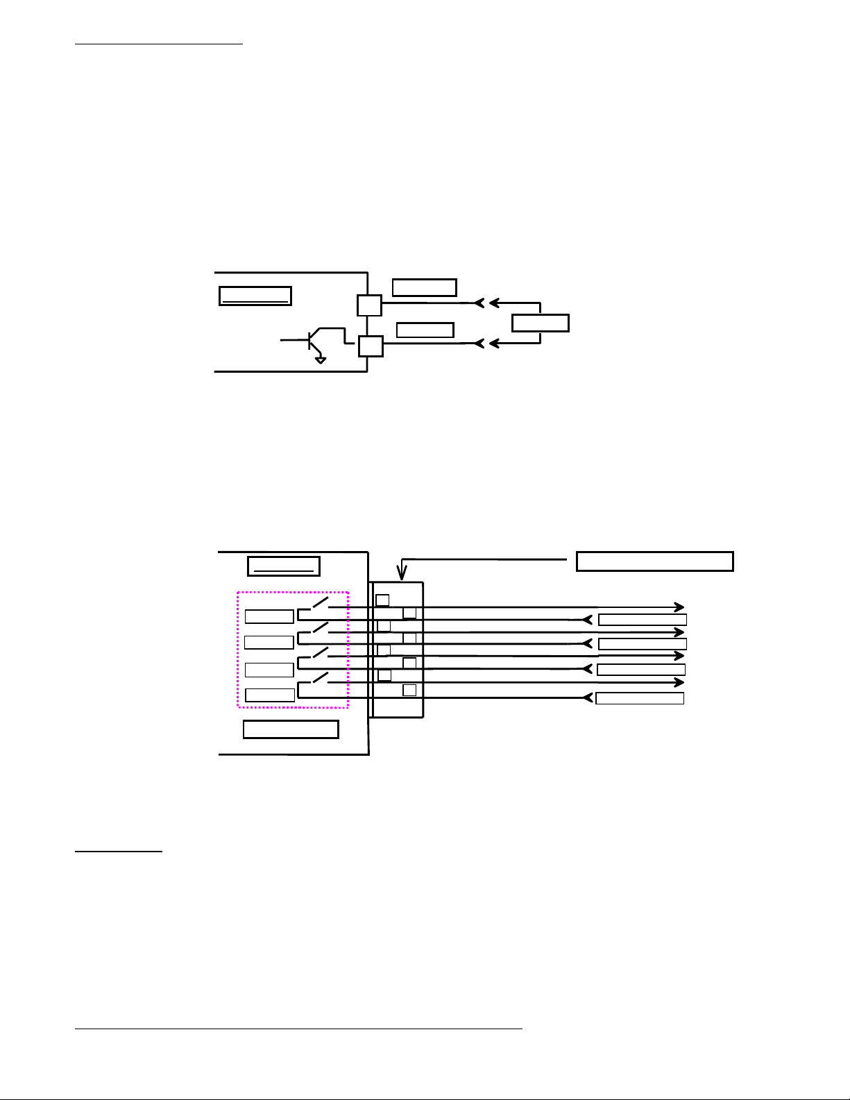
Open Collector (solid state) output Option:
DP3300 units can be ordered with either open collector outputs or electro-mechanical relays. (Check model number printed on
the unit for option). If ordered with open collector outputs, then these outputs are programmed during Setup to operate as either
Normally Open (NO) or Normally Closed (NC). The default setting is Normally Open.
Whenever a limit is reached, an open collector output provides a 5 Vdc signal at 50milliamp on the output connector, eg.. Limit
#1 provides its 5 volt output signal between pins 1 and 2.
Figure 1. Open Collector Hookup Example
Instrument
1
2
+OUTPUT
-OUTPUT
LOAD
Electro-Mechanical Relay Option:
DP3300 units can be ordered with either open collector outputs or electro-mechanical relays. (Check model number printed on
the unit for option). If ordered with relays, then these relays are programmed during Setup to operate as either Normally Open
(NO) or Normally Closed (NC). The default setting is Normally Open. Each of these limit relays provides a switched output
whenever a limit is reached. The maximum rating for a 120Vac unit is 120Vac @ 0.5 amp or 28 Vdc @ 1.0 amp. A 240Vac unit
is rated at 240Vac @ 0.25 amp. or 28Vdc @ 1.0 amp.
Figure 2. Electro-mechanical Relays Hookup Example
Instrument
LIMIT # 4
LIMIT # 3
LIMIT # 2
LIMIT # 1
8
7
6
5
4
3
2
1
LIMIT RELAYS
NOTE: LOOK UNDER SPECIFICATIONS FOR RATING ON RELAYS & OPEN COLLECTOR OUTPUTS.
UNDER NO CONDITION SHOULD THE RELAYS & OPEN COLLECTOR OUTPUTS BE OPERATED
BEYOND THEIR RATED CAPACITY. DOING SO CAN DAMAGE THE UNIT PERMANENTLY.
OUTPUT CONNECTOR
120 VAC @ 0.5 AMPS
120 VAC @ 0.5 AMPS
120 VAC @ 0.5 AMPS
120 VAC @ 0.5 AMPS
Switched Output
Switched Output
Switched Output
Switched Output
POWER
Power connection should be made to the three terminal connector as shown in figure 3. Also, make note that it is very important
that the power line inputs and the power ground are not switched. Doing so will permanently damage the instrument. Refer to the
schematic for proper connections. For convenience, the printed circuit board is labeled L1 L2 GND on the under side of
three terminal power connector.
For instruments with the 12Vdc power option, refer to Figure 3.
NOTE: WHILE MAKING POWER CONNECTION TO THE UNIT, MAKE SURE THAT AC POWER
LINE L1 OR L2 IS NOT ACCIDENTALLY CONNECTED INTO THE GROUND (GND)
TERMINAL. THIS WILL RESULT IN PERMANENT DAMAGE TO THE INSTRUMENT.
DOUBLE CHECK THE CONNECTIONS BEFORE APPLYING POWER!!
Page22
Page 24

DP3300 Series User’s Manual
_
+
_
_
_
FIG. 3: Power, Input/Output connections & rear view of the
instrument.
OFFSET
ADJUST
(For MV, T/C)
GAIN
ADJUST
(For MV, T/C
RTD, Thermistor)
+
15
15
16
CH1
ANG
INPUT
+
13
14
CH2
ANG
INPUT
VOLTAGE ADJUST
CURRENT ADJUST
INPUT/OUTPUT CONNECTOR
12
PULSE
INPUT
10 9 8 7 6 5 4 3 2 1
11
CH1
CH2
PULSE
INPUT
NEGATIVE
SUPPLY
(FOR DC POWER SUPPLY OPTION)
POWER
L1 L2
G
N
D
POSITIVE
SUPPLY
INPUT/OUTPUT CONNECTOR PIN ASSIGNMENTS
PIN NO DESCRIPTION
1 CHANNEL1, LIMIT 1 NORMALLY OPEN/OPEN COLLECTOR NEGATIVE
2 CHANNEL1, LIMIT 1 COMMON/OPEN COLLECTOR POSITIVE
3 CHANNEL1, LIMIT 2 NORMALLY OPEN/OPEN COLLECTOR NEGATIVE
4 CHANNEL1, LIMIT 2 COMMON/OPEN COLLECTOR POSITIVE
5 CHANNEL2, LIMIT 1 NORMALLY OPEN/OPEN COLLECTOR NEGATIVE
6 CHANNEL2, LIMIT 1 COMMON/OPEN COLLECTOR POSITIVE
7 CHANNEL2, LIMIT 2 NORMALLY OPEN/OPEN COLLECTOR NEGATIVE
8 CHANNEL2, LIMIT 2 COMMON/OPEN COLLECTOR POSITIVE
9 CHANNEL 2 PULSE INPUT – POSITIVE (+)
10 CHANNEL2 PULSE INPUT – NEGATIVE (-)
11 CHANNEL 1 PULSE INPUT – NEGATIVE (-)
12 CHANNEL 1 PULSE INPUT – POSITIVE (+)
13 CHANNEL 2 ANALOG INPUT – POSITIVE (+)
14 CHANNEL 2 ANALOG INPUT – NEGATIVE (-)
15 CHANNEL 1 ANALOG INPUT – NEGATIVE (-)
16 CHANNEL 1 ANALOG INPUT – POSITIVE (+)
NOTE: PINS ON THE CONNECTOR OTHER THAN THE ONES DESIGNATED ABOVE MUST NOT BE CONNECTED
TO ANY SIGNAL UNDER ANY CIRCUMSTANCES. ALSO PROPER CONNECTION AND CORRECT ORIENTATION
OF THE CONNECTOR ARE NECESSARY TO AVOID MALFUNCTION OR PERMANENT DAM AGE TO THE
INSTRUMENT.
Page23
Page 25

DP3300 Series User’s Manual
MOUNTING
3.70” (94mm)
0.15” dia. (3. 81 mm)
4.05 ” (10 2.87 mm)
Figure 4. Panel Cutout Dimensions
1. Cut out Panel and mounting hole dimensio ns as shown in figure 8 above .
2. Remove the nuts from the mounti ng screws on the Panel Meter (see pict ure below).
3. Insert panel meter into the hole until it is flush with the panel.
Install the nuts and tighten them till the unit is held firmly against the panel.
1. Remove nuts and insert Panel
Meter and screws in mounting holes
in the panel cut out.
1.77”
(45mm)
2. Tighten the nuts, after mounting
the unit in the panel cut out, till the
unit is held firmly against the panel.
Page24
Page 26

DP3300 Series User’s Manual
WARRANTY/DISCLAIMER
Page25
Page 27

DP3300 Series User’s Manual
Page26
Page 28

DP3300 Series User’s Manual
Page27
 Loading...