

Page 1
User’s Guide
Shop online at
omega.com
e-mail: [email protected]
For latest product manuals:
www.omegamanual.info
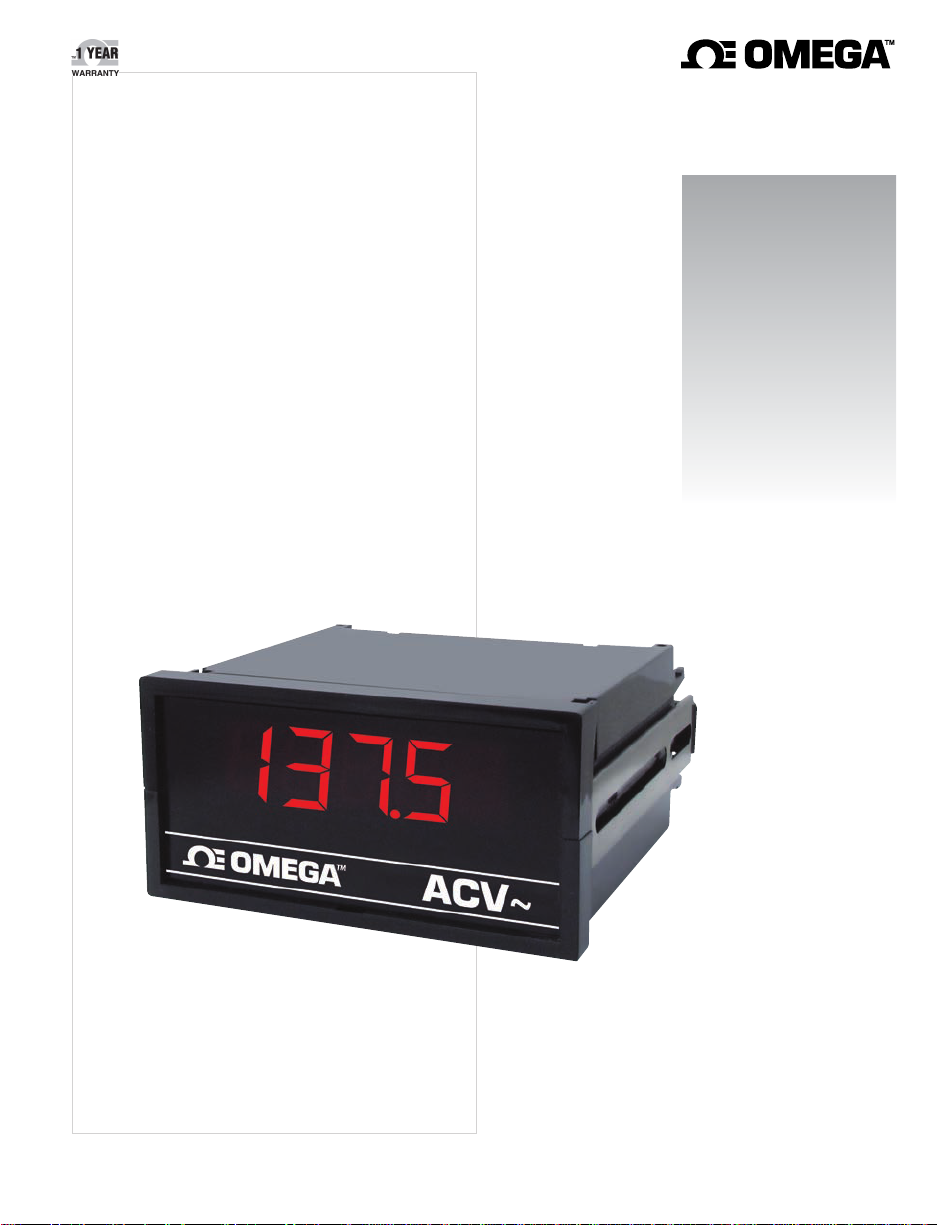
DP301AN DC VOLTMETER
DP301AN-AC VOLTMETER
Page 2

U.S.A.
Headquarters:
omega.com [email protected]
Servicing North America:
Omega Engineering, Inc.
Toll-Free: 1-800-826-6342 (USA & Canada only)
Customer Service: 1-800-622-2378 (USA & Canada only)
Engineering Service: 1-800-872-9436 (USA & Canada only)
Tel: (203) 359-1660
e-mail: [email protected]
For Other Locations Visit omega.com/worldwide
Fax: (203) 359-7700
The information contained in this document is believed to be correct, but OMEGA accepts no liability for any errors it
contains, and reserves the right to alter specifications without notice.
Page 3

TABLE OF CONTENTS
SAFETY INSTRUCTIONS ........................................................................................ iii
1.0 GENERAL INFORMATION ............................................................................... 1
2.0 SPECIFICATIONS ............................................................................................. 1
2.1 Analog Input ................................................................................................ 1
2.2 Accuracy at 25°C ......................................................................................... 2
2.3 Noise Rejection .......................................................................................... 2
2.4 Analog-To-Digital Conversion...................................................................... 2
2.5 3-Wire Ratio Reference ............................................................................... 2
2.6 Display ......................................................................................................... 2
2.7 Digital Signals ............................................................................................. 3
2.8 Power .......................................................................................................... 3
2.9 Environmental ............................................................................................. 3
2.10 Mechanical .................................................................................................. 3
3.0 MECHANICAL ASSEMBLY AND INSTALLATION ........................................... 4
3.1 Panel Mounting .......................................................................................... 4
4.0 POWER AND SIGNAL ...................................................................................... 6
4.1 Changing Operating Voltage ....................................................................... 6
4.2 Power and Signal Connections ................................................................... 6
4.3 Connector Pin Assignments ........................................................................ 8
4.4 Digital Test Signals ..................................................................................... 9
5.0 CONFIGURATION ..........................................................................................10
5.1 Decimal Point Selection ..............................................................................10
5.2 Voltage Range Selection .............................................................................11
5.3 Blanking Least-Significant Digit ..................................................................12
6.0 CALIBRATION ...................................................................................................13
6.1 DC Voltage Ranges ....................................................................................13
6.2 AC Voltage Ranges ....................................................................................13
7.0 DRAWINGS ......................................................................................................14
i
Page 4

ILLUSTRATIONS
Figure 3-1 DIN Case Dimensions ............................................................................. 4
Figure 3-2 Exploded View ....................................................................................... 5
Figure 4-1 Main Board ............................................................................................. 6
Figure 4-2 Rear Terminal ......................................................................................... 6
Figure 5-1 Display Board Jumper Locations ..........................................................10
Figure 5-2 Main Board Jumper Locations .............................................................11
Figure 5-3 Solder-Switch Locations .......................................................................12
Figure 7-1 Assembly Diagram .................................................................................14
ii
Page 5
SAFETY CONSIDERATIONS
This device is marked with the international Caution symbol. It is important to read
this manual before installing or commissioning this device as it contains important
information relating to Safety and EMC (Electromagnetic Compatibility).
Unpacking & Inspection
Unpack the instrument and inspect for obvious shipping damage. Do not attempt to
operate the unit if damage is found.
This instrument is a panel mount device protected in accordance with Class I of
EN 61010 (115/230 AC power connections). Installation of this instrument should be done
by Qualified personnel. In order to ensure safe operation, the following instructions should
be followed.
This instrument has no power-on switch. An external switch or circuit-breaker shall be
included in the building installation as a disconnecting device. It shall be marked to
indicate this function, and it shall be in close proximity to the equipment within easy reach
of the operator. The switch or circuit-breaker shall not interrupt the Protective Conductor
(Earth wire), and it shall meet the relevant requirements of IEC 947–1 and IEC 947-3
(International Electrotechnical Commission). The switch shall not be incorporated in the
mains supply cord.
Furthermore, to provide protection against excessive energy being drawn from the mains
supply in case of a fault in the equipment, an overcurrent protection device shall be
installed.
• The Protective Conductor must be connected for safety reasons. Check that
the power cable has the proper Earth wire, and it is properly connected. It is not
safe to operate this unit without the Protective Conductor Terminal connected.
• Do not exceed voltage rating on the label located on the top of the
instrument housing.
• Always disconnect power before changing signal and power connections.
• Do not use this instrument on a work bench without its case for safety
reasons.
• Do not operate this instrument in flammable or explosive atmospheres.
• Do not expose this instrument to rain or moisture.
• Unit mounting should allow for adequate ventilation to ensure instrument
does not exceed operating temperature rating.
• Use electrical wires with adequate size to handle mechanical strain and
power requirements. Install without exposing bare wire outside the connector
to minimize electrical shock hazards.
EMC Considerations
• Whenever EMC is an issue, always use shielded cables.
• Never run signal and power wires in the same conduit.
• Use signal wire connections with twisted-pair cables.
• Install Ferrite Bead(s) on signal wires close to the instrument if
EMC problems persist.
iii
Page 6

1.0 GENERAL INFORMATION
The two versions of voltmeters are different pinout versions of the same 3 1/2
digit panel meter for applications which require a compact, quality dc voltmeter.
Standard features include HOLD function, selectable decimal point location and
LAMP TEST.
Each model contains the circuitry for all ranges. The range is changed by
opening and closing the appropriate switches on the printed circuit board via
installation of push-on jumpers.
1.1 MODEL DP301AN
Model DP301AN is pin compatible with newer voltmeters DP302, DP3001 and
DP3002 series.
Models DP301AN has a resolution of 1 part in ±1999 counts, or 0.05% of full
scale. By using an external dc voltage reference, any of these ranges can be
configured for 3 wire ratio measurement with readout from 0 to 1.999.
1.2 MODEL DP301AN-AC
Model DP301AN-AC, for AC power line monitoring, has a screw terminal barrier
strip for signal and power. This model uses a half wave average converter
calibrated to read RMS. It offers input ranges of 199.9 and 650 V ac, with
resolution of 100 mV and 1 V, respectively. Maximum rated input in either range is
650 V RMS or 920 Vp.
2.0 SPECIFICATIONS
2.1 ANALOG INPUT
Model "AN"
Signal ranges ±199.9mV ±1.999V ±19.99V ±199.9V
Bias current 50 pA 50 pA 5 pA 1 pA
Maximum input 130 Vp 130 Vp 250 Vp 250 Vp
Resolution 100 uV 1 mV 10 mV 100 mV
Input resistance 1 GΩ 1 GΩ 1.1 MΩ 1.0 M^N8,50
Configuration Differential, bipolar
Zero Automatic
Span adjustment ±5%
Model "AN-AC"
Signal ranges 199.9 V ac 650 V ac
Bias current 1 pA 1 pA
Overvoltage protection 650 V ac 650 V ac
Resolution 100 mV 1 V ac
Input resistance 1 MΩ 1 MΩ
Configuration Half wave average, RMS calibrated
Zero Automatic
Frequency 47 to 1000 Hz
1
Page 7

2.2 ACCURACY AT 25°C
Warmup to rated accuracy 10 minutes
Model "AN"
Maximum error ±0.05% or reading °1 count
Span to tempco ±0.01% of reading/°C
Step response 1 second
Model "AN-AC" (10% to 100% of full-scale range)
Maximum error (actual reading)
20.0 to 199.9 V range ±0.003%FS (R-110 V) / V ±1 counts
20.0 to 650. V range ±0.003%FS (R-220 V) / V ±1 counts
Span to tempco ±0.01% of reading / °C
Step response 1 second
2.3 NOISE REJECTION
NMR 56 dB at 50/60 Hz
CMR, SIG LO to SIG GND 80 dB, DC to 60 Hz
CMV, SIG LO to SIG GND ±1.0 Vp
CMR, AC GND to SIG GND 120 dB, DC to 60 Hz
CMV, AC GND to SIG GND 1500 Vp per HV test; 354 Vp per IEC spacing
2.4 ANALOG TO DIGITAL CONVERSION
Technique Dual-slope, average-value
Read rate 2.5/second
Input integration period 100 milliseconds
2.5 3 WIRE RATIO REFERENCE
Model "AN"
Analog input range ±200 mV, ±2 V, ±20 V, ±200 V
Reference voltage +0.05 to +0.2 V +0.5 to 2.0 V
Load on reference 30.6 ohms 65.3 ohms
Accuracy 99.9%R 99.9%R
2.6 DISPLAY
Type 7 segment, red LED; 14.2 mm (0.56 in)
Symbols
Model "AN" -1.8.8.8
Model "AN AC" 1.8.8.8
Decimal points 3 position progr ammable internally or at connect or
Overrange indication 3 least significant digits blank
2
Page 8

2.7 DIGITAL SIGNALS (Referenced to SIG GND)
Logical 0 0 to +1.4 V
Logical 1 +3.7 V to +5.0 V
Display HOLD 1 = latched reading
LAMP TEST 1 = display of -1888
Output voltage +4.7 V dc ±5% at 10 mA max
-4.6 V dc ±5% at 10 mA max
2.8 POWER
AC input voltage 115 or 230 V ac ±15%
AC frequency range 49 to 440 Hz
DC input voltage 9 to 32 V dc, isolated to 300 Vp
26 to 56 V dc, isolated to 300 Vp
Power consumption 2.4 W (nominal)
2.9 ENVIRONMENTAL
Operating temperature 0 to +60°C
Storage temperature -40 to +85°C
Relative humidity 95% at +40°C (non-condensing)
2.10 MECHANICAL
Bezel 96 x 48 x 6.1 mm (3.78 x 1.89 x 0.24 in)
Depth behind bezel,
with connector 99 mm (3.90 in)
Panel cutout 92 x 45 mm (3.62 x 1.77 in)
Weight 400 g (14 oz)
Case material 94V-O UL rated polycarbonate
D1 connector: 18 pin, double row, 3.96 mm (0.156 in) pin spacing
D4 connector: Screw terminal barrier strip for signal and power
(removes these inputs from D1)
3
Page 9
3.0 MECHANICAL ASSEMBLY AND INSTALLATION
3.1 PANEL MOUNTING
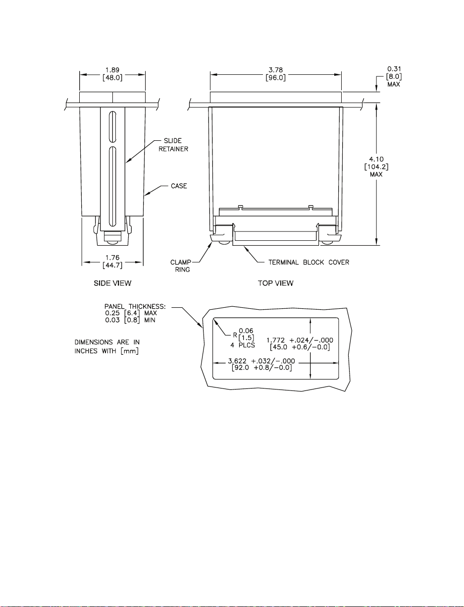
Figure 3-1 DIN Case Dimensions
1. Remove the main board edge connector (J1) if installed.
2. Use a #8 Phillips-head screwdriver to loosen the two screws on the rear of
the case until you can rotate the two clamp rings. Loosen the screws enough
to allow for the panel thickness.
3. Slide the two slide retainers towards the rear of the unit and remove them.
4. Observe the case dimensions previously shown. From the front of the panel,
insert the meter into the panel cutout.
5. Slide the slide retainers back onto the case and push up tightly against the
rear of the panel.
6. Rotate the clamp rings back into their original position and tighten until the
case is held in place. Do not overtighten.
7. Reinstall any connectors that were removed
4
Page 10
3.1 PANEL MOUNTING (continued)
WARNING: High voltage is present when using model "AN-AC" with the
650 V AC option.
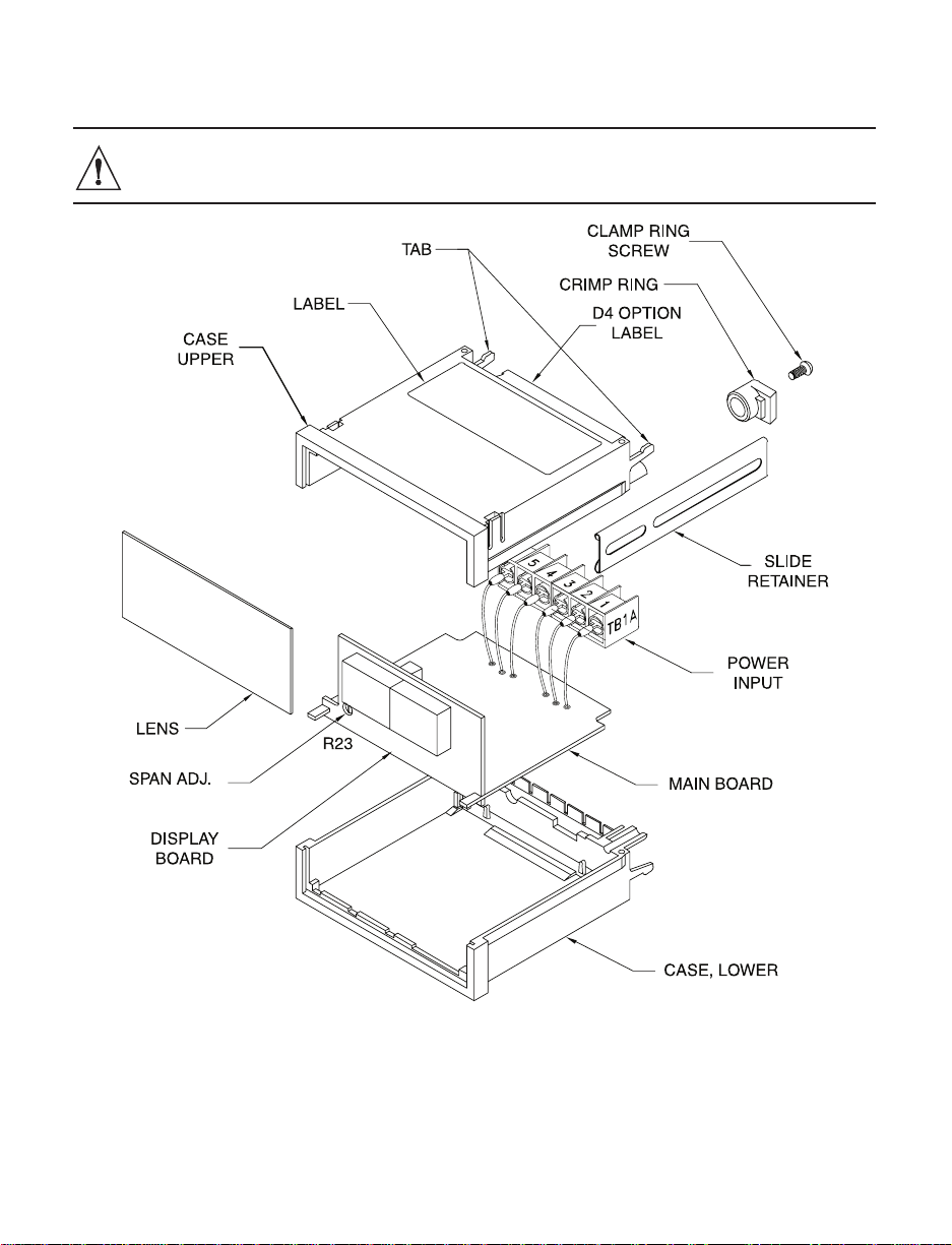
Figure 3-2 Exploded View
5
Page 11
4.0 POWER AND SIGNAL
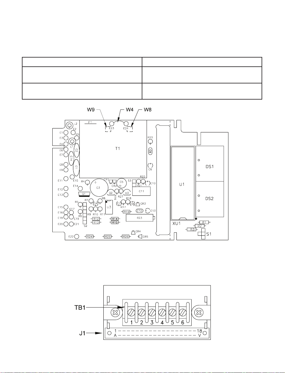
4.1 CHANGING OPERA TING VOL TA GE
Remove power lines from the meter, then remove the meter from the case.
OPERA TING VOLT A GE JUMPER INSTALLATION
230 V ac ±15% (Option C1)
115 V ac ±15% (Standard)
Remove W8 and W9 on the transformer
Install W4 on the printed circuit board
Install W8 and W9 on the transformer
Remove W4 on the printed circuit board
Figure 4-1 Main Board
4.2 POWER AND SIGNAL CONNECTIONS
The voltmeters are factory-set for 115 V ac ±15% operation.
Power and signal can be connected using the D1 or D4 option.
(D4)
(D1)
Figure 4-2 Rear Terminal
6
Page 12
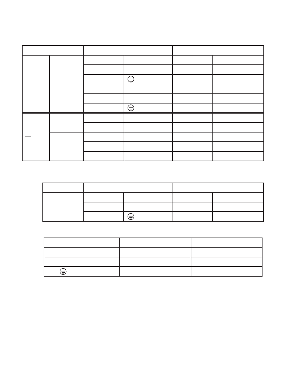
Refer to Figure 4-2.
MODEL "AN"
Connector Power Signal
A L (High) 17 High
D1
~ AC
D4
D1
DC
D4
Model "AN-AC"
Connector Power Signal
D4
2 N (Low) 16 Low
C (Ground)
1 L (High) 6 High
2 N (Low) 5 Low
3 (Ground) 4 Signal GRND
2 + DC 17 High
C - DC (return) 16 Low
1 No connection 6 High
2 + DC 5 Low
3 - DC (return) 4 Signal GRND
1 L (High) 6 High
2 N (Low) 5 Low
3 (Ground) 4 No connection
Wire Color for AC Power USA Other
L (High) Black Brown
N (Low) White Blue
(Ground) Green Green
7
Page 13

4.3 CONNECTOR PIN ASSIGNMENTS
Model "AN-AC" J1 Connector (D1 Option)
Spare
N/C
Spare
N/C
Spare
N/C
199.9 DP
19.99 DP
1.999 DP
LAMP TEST
+4.7 V
-4.6 V
+REF
HOLD
ANA GND
SIG LO
N/C
Spare
A 1 N/C
B 2 N/C
C 3 N/C
D 4 N/C
E 5 N/C
F 6 N/C
H 7 199.9 DP
J 8 19.99 DP
K 9 1.999 DP
L 10 LAMP TEST
M 11 +4.7 V
N 12 -EXC
P 13 +EXC
R 14 HOLD
S 15 Spare
T 16 Spare
U 17 Spare
V 18 N/C
Model "AN" J1 Connector (D1 Option)
AC HI
N/C
AC GND/-DC PWR
N/C
Spare
N/C
199.9 DP
19.99 DP
1.999 DP
LAMP TEST
+4.7 V
-4.6 V
+REF
HOLD
ANA GND
SIG LO
N/C
SIG HI
A 1 N/C
B 2 AC LO/+DC PWR
C 3 N/C
D 4 N/C
E 5 N/C
F 6 DIG GND
H 7 199.9 DP
J 8 19.99 DP
K 9 1.999 DP
L 10 LAMP TEST
M 11 +4.7 V
N 12 -EXC
P 13 +EXC
R 14 HOLD
S 15 Spare
T 16 SIG LO
U 17 SIG HI
V 18 N/C
8
Page 14

Connector TB1 (D4 Option)
~ AC Power Versions DC Power V ersions
1 AC HI L 1 N/C
2 AC LO N 2 +DC PWR
3 AC GND 3 -DC PWR RETURN
4 ANA GND* 4 ANA GND*
5 SIG LO 5 SIG LO
6 SIG HI 6 SIG HI
* No connection with "AN-AC"
4.4 DIGIT AL TEST SIGNALS
Display HOLD instructs the meter to maintain a display of the last reading.
To activate HOLD, connect J1-pin 14/R to J1-pin 11/M.
LAMP TEST instructs the meter to light the minus sign and all digits on the
display to verify that the display is operating properly. To test the display, connect
J1-pin 10/L to J1-pin 11/M. The decimal point does not light when LAMP TEST is
activated.
9
Page 15
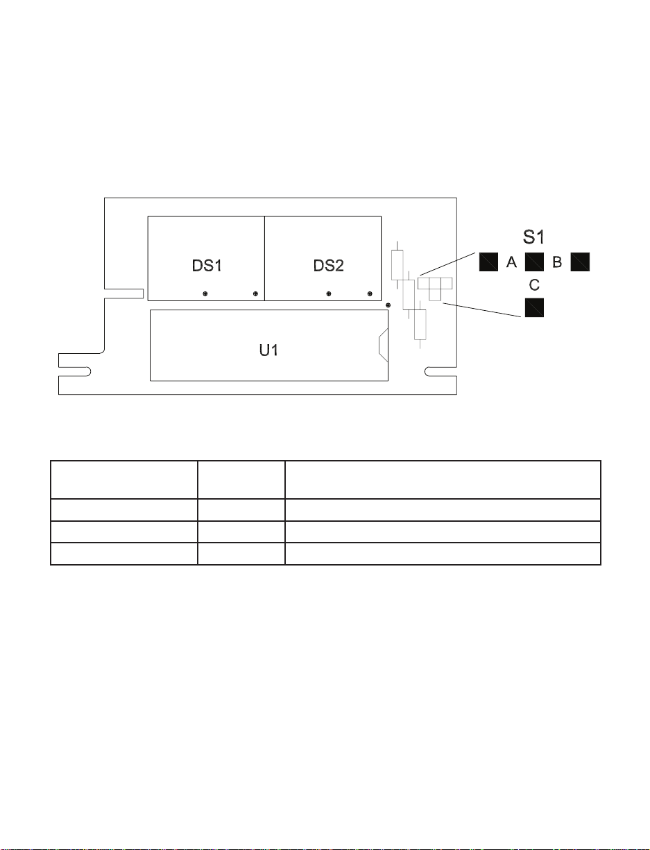
5.0 CONFIGURATION
Select the desired configurations from the following charts.
Install jumpers and open/close solder switches as indicated.
Remove all push-on jumpers not used.
5.1 DECIMAL POINT SELECTION
Figure 5-1 Display Board Jumper Locations
Decimal Point S1
Alternate Decimal Point Configuration Using
Main Board Connector J1
1.999 A Connect K/9 to 6
19.99 C Connect J/8 to 6
199.9 B Connect H/7 to 6
10
Page 16
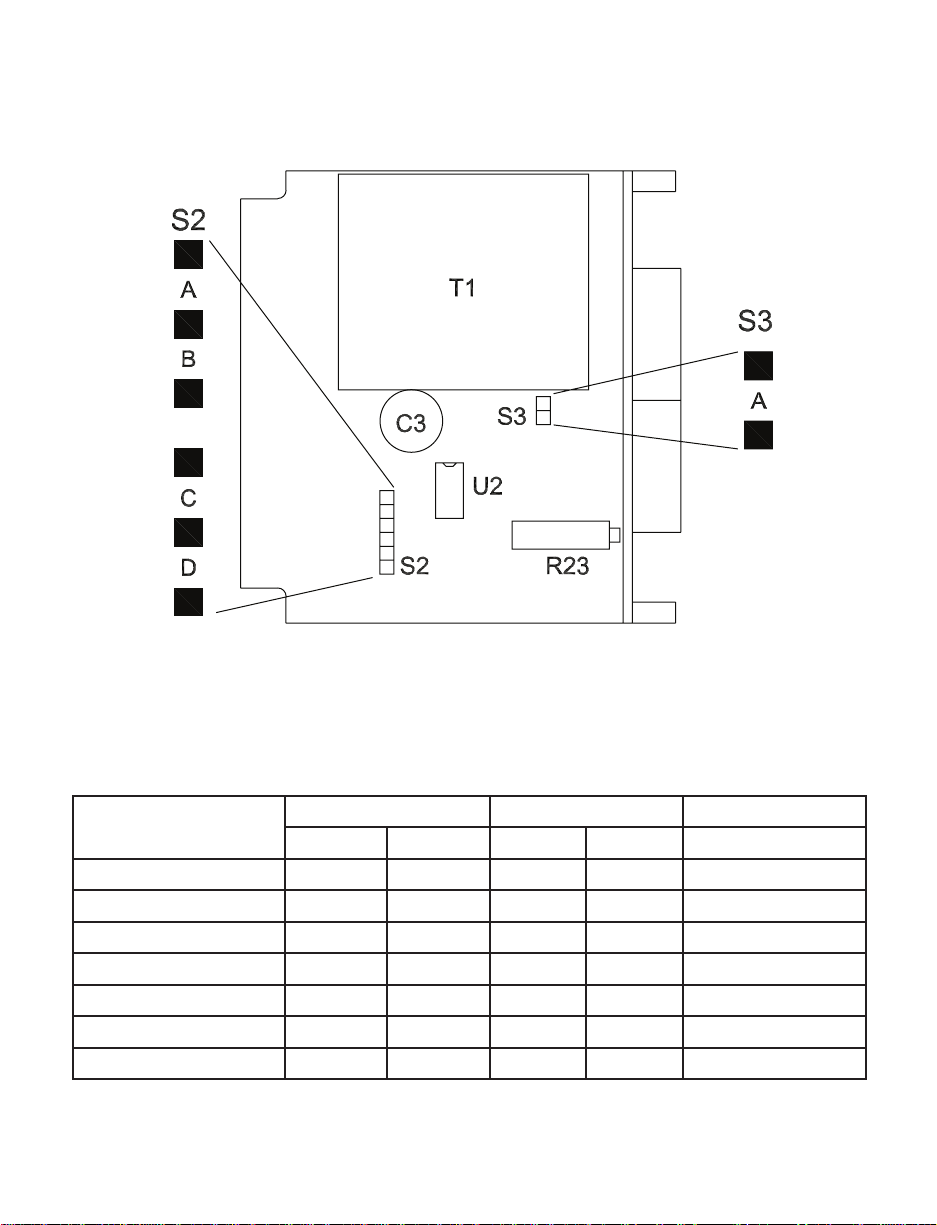
5.2 VOLTAGE RANGE SELECTION
Figure 5-2 Main Board Jumper Locations
Input Configuration
Solder Switches* Push-on Jumpers Remove Jumper
Open Close S2 S3 Wire
200 mV dc - - A A
2 V dc - - B -
20 V dc - - B, C 200 V dc - - B, D 200 V ac I G, K, J B - E-17 to TB1B-4
650 V ac I H, K, J B - E-17 to TB1B-4
True-differential C - - - -
* Refer to Figure 5-3 on the following page for solder switch locations.
11
Page 17
5.3 BLANKING THE LEAST-SIGNIFICANT DIGIT
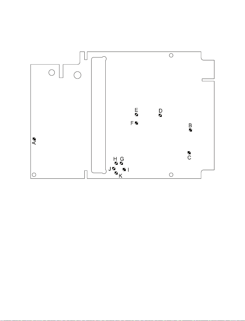
To blank the least-significant digit, open solder switch 'A' on the circuit side of the
display board.
Figure 5-3 Solder Switch Locations
12
Page 18

6.0 CALIBRATION
6.1 DC VOL TA GE RANGES
1. Remove the front lens. Insert a blade screwdriver under the notch at the
bottom of the lens and gently pry it off.
2. Short the input signal connections and verify that the display reads zero.
3. Apply an input voltage equal to 95% of the high end of the range selected.
4. Locate the Span potentiometer (R23) in Figure 3-2. Adjust until the display
reads 1900 ±1 count.
6.2 AC V OL T A GE RANGES
1. Follow steps 1 and 2 from above.
2. Apply an input voltage equal to 110.0 V ac at 50 or 60 Hz on 200 V ac range
or 220 V ac at 50 or 60 Hz on 650 V ac range.
3. Locate the Span potentiometer (R23) in Figure 3-2. Adjust until the display
reads:
110.0 on 200 V ac range
220 on 650 V ac range
13
Page 19
7.0 DRAWINGS
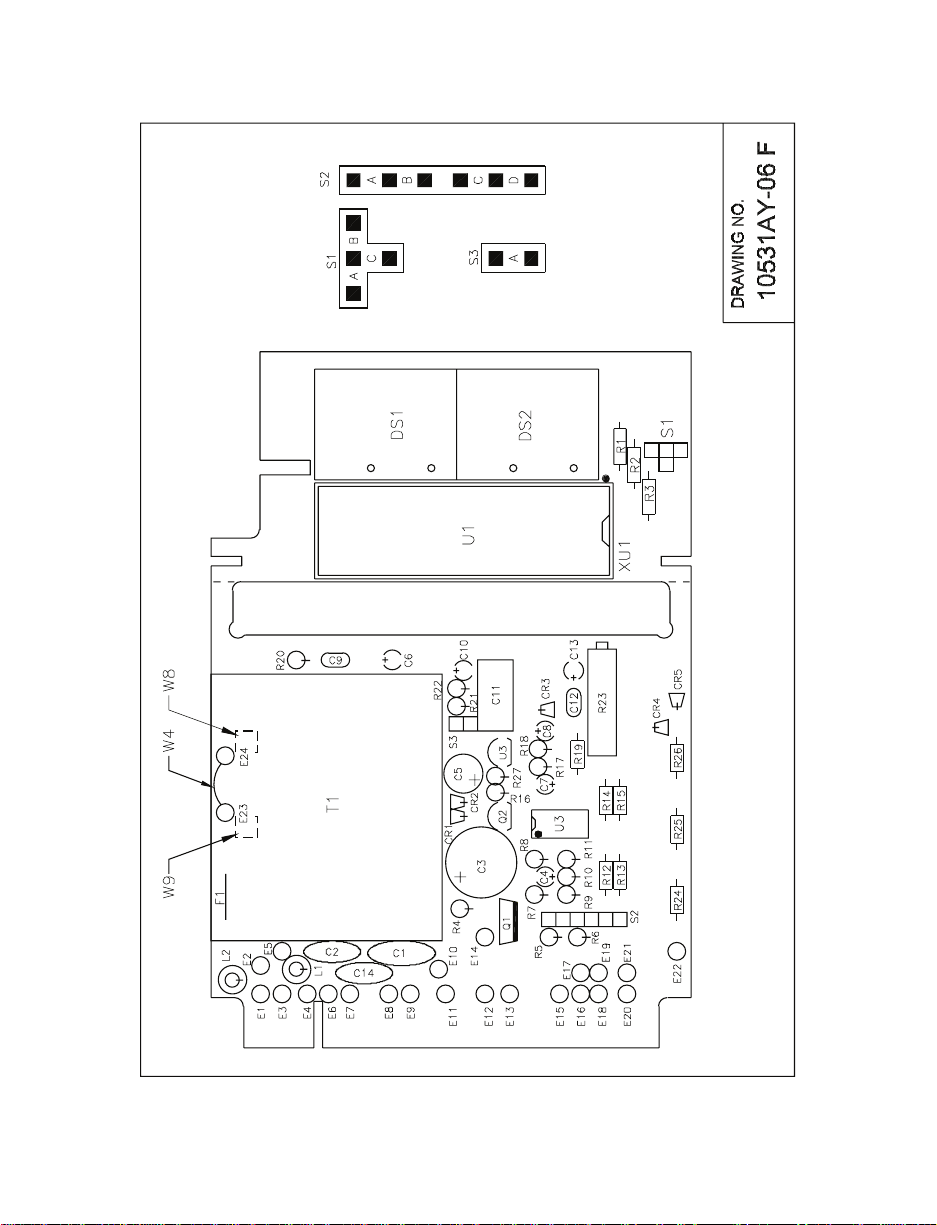
Figure 7-1 Assembly Diagram
14
Page 20

NOTES
15
Page 21

WARRANTY/DISCLAIMER
OMEGA ENGINEERING, INC. warrants this unit to be free of defects in materials and workmanship for a period of 13 months from date of purchase. OMEGA Warranty adds an additional one (1) month grace period to
the normal one (1) year product warranty to cover handling and shipping time. This ensures that OMEGA’s
customers receive maximum coverage on each product.
If the unit should malfunction, it must be returned to the factory for evaluation. OMEGA’s Customer Service
Department will issue an Authorized Return (AR) number immediately upon phone or written request. Upon
examination by OMEGA, if the unit is found to be defective it will be repaired or replaced at no charge.
OMEGA’s WARRANTY does not apply to defects resulting from any action of the purchaser, including
but not limited to mishandling, improper interfacing, operation outside of design limits, improper repair, or
unauthorized modification. This WARRANTY is VOID if the unit shows evidence of having been tampered
with or shows evidence of being damaged as a result of excessive corrosion; or current, heat, moisture or
vibration; improper specification; misapplication; misuse or other operating conditions outside of OMEGA’s
control. Components which wear are not warranted, including but not limited to contact points, fuses, and
triacs.
OMEGA is pleased to offer suggestions on the use of its various products. However, OMEGA neither
assumes responsibility for any omissions or errors nor assumes liability for any damages that result from
the use of its products in accordance with information provided by OMEGA, either verbal or written.
OMEGA warrants only that the parts manufactured by it will be as specified and free of defects. OMEGA
MAKES NO OTHER WARRANTIES OR REPRESENTATIONS OF ANY KIND WHATSOEVER, EXPRESSED OR
IMPLIED, EXCEPT THAT OF TITLE, AND ALL IMPLIED WARRANTIES INCLUDING ANY WARRANTY OF
MERCHANTABILITY AND FITNESS FOR A PARTICULAR PURPOSE ARE HEREBY DISCLAIMED. LIMITATION
OF LIABILITY: The remedies of purchaser set forth herein are exclusive and the total liability of OMEGA with
respect to this order, whether based on contract, warranty, negligence, indemnification, strict liability or
otherwise, shall not exceed the purchase price of the component upon which liability is based. In no event
shall OMEGA be liable for consequential, incidental or special damages.
CONDITIONS: Equipment sold by OMEGA is not intended to be used, nor shall it be used: (1) as a “Basic
Component” under 10 CFR 21 (NRC), used in or with any nuclear installation or activity; or (2) in medical
applications or used on humans. Should any Product(s) be used in or with any nuclear installation or activity,
medical application, used on humans, or misused in any way, OMEGA assumes no responsibility as set forth
in our basic WARRANTY / DISCLAIMER language, and additionally, purchaser will indemnify OMEGA and hold
OMEGA harmless from any liability or damage whatsoever arising out of the use of the Product(s) in such a
manner.
RETURN REQUESTS / INQUIRIES
Direct all warranty and repair requests/inquiries to the OMEGA Customer Service Department. BEFORE
RETURNING ANY PRODUCT(S) TO OMEGA, PURCHASER MUST OBTAIN AN AUTHORIZED RETURN
(AR) NUMBER FROM OMEGA’S CUSTOMER SERVICE DEPARTMENT (IN ORDER TO AVOID PROCESSING DELAYS). The assigned AR number should then be marked on the outside of the return package and
on any correspondence.
The purchaser is responsible for shipping charges, freight, insurance and proper packaging to prevent
breakage in transit.
FOR WARRANTY RETURNS, please have the
following information available BEFORE
contacting OMEGA:
1. P.O. number under which the product
was PURCHASED,
2. Model and serial number of the product
under warranty, and
3. Repair instructions and/or specific
problems relative to the product.
FOR NON-WARRANTY REPAIRS,
consult
OMEGA for current repair charges. Have
the following information available BEFORE
contacting OMEGA:
1. P.O. number to cover the COST
of the repair,
2. Model and serial number of product, and
3. Repair instructions and/or specific
problems relative to the product.
OMEGA’s policy is to make running changes, not model changes, whenever an improvement is possible. This
affords our customers the latest in technology and engineering. OMEGA is a registered trademark of OMEGA
ENGINEERING, INC. © Copyright 2012 OMEGA ENGINEERING, INC. All rights reserved. This document may not
be copied, photocopied, reproduced, translated, or reduced to any electronic medium or machine-readable form,
in whole or in part, without prior written consent of OMEGA ENGINEERING, INC.
Page 22

Where Do I Find Everything I Need for
Process Measurement and Control?
OMEGA…Of Course!
TEMPERATURE
Thermocouple, RTD & Thermistor Probes, Connectors, Panels & Assemblies
Wire: Thermocouple, RTD & Thermistor
Calibrators & Ice Point References
Recorders, Controllers & Process Monitors
Infrared Pyrometers
PRESSURE, STRAIN AND FORCE
Transducers & Strain Gauges
Load Cells & Pressure Gauges
Displacement Transducers
Instrumentation & Accessories
FLOW/LEVEL
Rotameters, Gas Mass Flowmeters & Flow Computers
Air Velocity Indicators
Turbine/Paddlewheel Systems
Totalizers & Batch Controllers
pH/CONDUCTIVITY
pH Electrodes, Testers & Accessories
Benchtop/Laboratory Meters
Controllers, Calibrators, Simulators & Pumps
Industrial pH & Conductivity Equipment
M5224/0818
DATA ACQUISITION
Data Acquisition & Engineering Software
Communications-Based Acquisition Systems
Plug-in Cards for Apple, IBM & Compatibles
Datalogging Systems
Recorders, Printers & Plotters
HEATERS
Heating Cable
Cartridge & Strip Heaters
Immersion & Band Heaters
Flexible Heaters
Laboratory Heaters
ENVIRONMENTAL MONITORING
AND CONTROL
Metering & Control Instrumentation
Refractometers
Pumps & Tubing
Air, Soil & Water Monitors
Industrial Water & Wastewater Treatment
pH, Conductivity & Dissolved Oxygen Instruments
 Loading...