

Page 1
USA
MADE IN
This device is marked with the international caution symbol. It is important
to read the Setup Guide before installing or commissioning this device as
it contains important information relating to safety and EMC.
It is the policy of OMEGA to comply with all worldwide safety and EMC/EMI
regulations that apply. OMEGA is constantly pursuing certification of its products to
the European New Approach Directives. OMEGA will add the CE mark to every
appropriate device upon certification.
The information contained in this document is believed to be correct but OMEGA
Engineering, Inc. accepts no liability for any errors it contains, and reserves the right
to alter specifications without notice.
TRADEMARK NOTICE:
®
omega.com
®
, and ,
are trademarks of OMEGA Engineering, Inc.
®
WARNING: These products are not designed for use in, and should not be used
for, patient connected applications.
M1988/1205 11975ML-99 Rev B
WARRANTY/DISCLAIMER
OMEGA ENGINEERING, INC. warrants this unit to be free of defects in
materials and workmanship for a period of one (1) year from the date of
purchase. In addition to OMEGA’s standard warranty period, OMEGA
Engineering will extend the warranty period for four (4) additional years if the
warranty card enclosed with each instrument is returned to OMEGA.
If the unit malfunctions, it must be returned to the factory for evaluation.
OMEGA’s Customer Service Department will issue an Authorized Return (AR)
number immediately upon phone or written request. Upon examination by
OMEGA, if the unit is found to be defective, it will be repaired or replaced at no
charge. OMEGA’s WARRANTY does not apply to defects resulting from any
action of the purchaser, including but not limited to mishandling, improper
interfacing, operation outside of design limits, improper repair, or unauthorized
modification. This WARRANTY is VOID if the unit shows evidence of having
been tampered with or shows evidence of having been damaged as a result of
excessive corrosion; or current, heat, moisture or vibration; improper
specification; misapplication; misuse or other operating conditions outside of
OMEGA’s control. Components which wear are not warranted, including but not
limited to contact points, fuses, and triacs.
OMEGA is pleased to offer suggestions on the use of its various products.
However, OMEGA neither assumes responsibility for any omissions or
errors nor assumes liability for any damages that result from the use of its
products in accordance with information provided by OMEGA, either
verbal or written. OMEGA warrants only that the parts manufactured by it
will be as specified and free of defects. OMEGA MAKES NO OTHER
WARRANTIES OR REPRESENTATIONS OF ANY KIND WHATSOEVER,
EXPRESS OR IMPLIED, EXCEPT THAT OF TITLE, AND ALL IMPLIED
WARRANTIES INCLUDING ANY WARRANTY OF MERCHANTABILITY AND
FITNESS FOR A PARTICULAR PURPOSE ARE HEREBY DISCLAIMED.
LIMITATION OF LIABILITY: The remedies of purchaser set forth herein are
exclusive, and the total liability of OMEGA with respect to this order,
whether based on contract, warranty, negligence, indemnification, strict
liability or otherwise, shall not exceed the purchase price of the
component upon which liability is based. In no event shall OMEGA be
liable for consequential, incidental or special damages.
CONDITIONS: Equipment sold by OMEGA is not intended to be used, nor shall
it be used: (1) as a “Basic Component” under 10 CFR 21 (NRC), used in or with
any nuclear installation or activity; or (2) in medical applications or used on
humans. Should any Product(s) be used in or with any nuclear installation or
activity, medical application, used on humans, or misused in any way, OMEGA
assumes no responsibility as set forth in our basic WARRANTY/DISCLAIMER
language, and, additionally, purchaser will indemnify OMEGA and hold OMEGA
harmless from any liability or damage whatsoever arising out of the use of the
Product(s) in such a manner.
RETURN REQUESTS / INQUIRIES
Direct all warranty and repair requests/inquiries to the OMEGA Customer Service
Department. BEFORE RETURNING ANY PRODUCT(S) TO OMEGA,
PURCHASER MUST OBTAIN AN AUTHORIZED RETURN (AR) NUMBER
FROM OMEGA’S CUSTOMER SERVICE DEPARTMENT (IN ORDER TO AVOID
PROCESSING DELAYS). The assigned AR number should then be marked on
the outside of the return package and on any correspondence.
The purchaser is responsible for shipping charges, freight, insurance and proper
packaging to prevent breakage in transit.
FOR WARRANTY RETURNS, please
have the following information available
BEFORE contacting OMEGA:
1. P.O. number under which the
product was PURCHASED,
2. Model and serial number of the
product under warranty, and
3. Repair instructions and/or specific
problems relative to the product.
FOR NON-W
ARRANTY REPAIRS,
consult OMEGA for current repair
charges. Have the following information
available BEFORE contacting OMEGA:
1. P.O. number to cover the COST of
the repair,
2. Model and serial number of product,
and
3. Repair instructions and/or specific
problems relative to the product.
OMEGA’s policy is to make running changes, not model changes, whenever an
improvement is possible. This affords our customers the latest in technology and
engineering.
OMEGA is a registered trademark of OMEGA ENGINEERING, INC.
© Copyright 2005 OMEGA ENGINEERING, INC. All rights reserved.
This document may not be copied, photocopied, reproduced, translated, or reduced
to any electronic medium or machine-readable form, in whole or in part, without
prior written consent of OMEGA ENGINEERING, INC.
PATENT NOTICE: This product is covered by one or more of the following
patents: U.S. Pat. No. Des. 336,895; 5,274,577; 6,243,021 / CANADA 2052599;
2052600 / ITALY 1249456; 1250938 / FRANCE BREVET No. 91 12756 / SPAIN
2039150; 2048066 / UK PATENT No. GB2 249 837; GB2 248 954 / GERMANY
DE 41 34398 C2. The “Meter Case Bezel Design” is a trademark of NEWPORT
Electronics, Inc. USED UNDER LICENSE. Other U.S. and International patents
pending or applied for.
56
DP25-CRMS, DP25-VRMS
MICROPROCESSOR-BASED
TRUE RMS METER
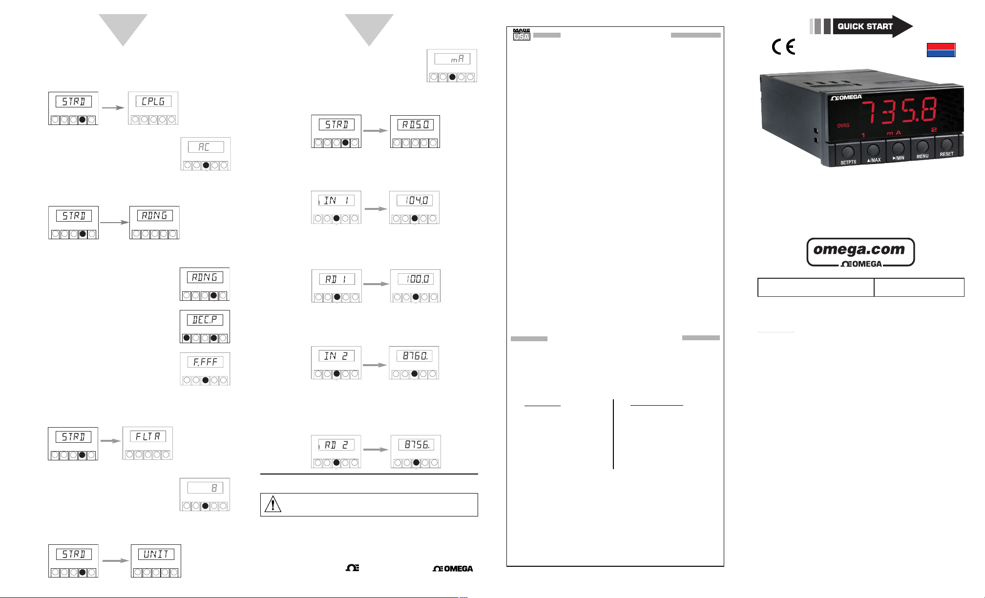
Set Coupling (continued)
6. Press MENU to select the frequency shown.
The meter displays:
7. Press /MIN. The meter flashes the
current coupling selection. Press /MAX
to scroll through choices. Your choices
are: AC or DC coupling.
8. Press MENU to select the coupling type.
The meter displays:
To Set Up Reading Configuration
1. If necessary, press MENU until the meter
displays:
2. Press SETPTS, followed by MENU until
the meter displays:
3. Press /MIN. The meter flashes the
current decimal point setup. Press
/MAX to scroll through choices.
Your choices are F.FFF, FF.FF, FFF.F
and FFFF.
4. Press MENU to select the decimal point shown. The
meter displays:
5. Press /MIN. The meter flashes the
filter value. Press /MAX to scroll
through choices. Your choices are 0, 4,
8, 16 & 64.
6. Press MENU to select the filter value shown.
The meter displays:
7. Press /MIN. The meter flashes the
unit value. Press /MAX to scroll
through choices. Your choices are
V (A) and mV (mA).
8. Press MENU to select the unit value shown.
The meter displays:
9. Press /MIN. The meter displays “IN 1”. Press /MIN
to show the unscaled value. Press /MIN and /MAX
to enter the desired value.
10. Press MENU to select value. The meter displays “RD 1”
(desired display at Input 1). Press /MIN and /MAX
to enter the desired value.
11. Press MENU to select value. The meter displays “IN 2” .
Press /MIN to show the unscaled value. Press /MIN
and /MAX to enter the desired value.
12. Press MENU to select value. The meter displays “RD 2”
(desired display at Input 2). Press /MIN and /MAX
to enter the desired value. Reading Configuration is now
complete.
SETPTS
/MAX
SETPTS
/MAX
/MIN
RESET
MENU
SETPTS
/MAX
/MIN
RESET
MENU
SETPTS
/MAX
/MIN
RESET
MENU
SETPTS
/MAX
/MIN
RESET
MENU
/MIN
RESET
MENU
SETPTS
SETPTS
/MAX
/MIN
RESET
MENU
SETPTS
SETPTS
SETPTS
SETPTS
/MAX
/MIN
RESET
MENU
SETPTS
SETPTS
/MIN
RESET
/MAX
MENU
SETPTS
/MAX
/MIN
RESET
MENU
SETPTS
/MAX
/MIN
RESET
MENU
/MIN
RESET
/MAX
MENU
SETPTS
/MAX
/MIN
RESET
MENU
/MIN
SETPTS
RESET
/MAX
MENU
/MIN
SETPTS
RESET
/MAX
MENU
/MAX
/MIN
RESET
MENU
/MIN
SETPTS
RESET
/MAX
MENU
/MIN
SETPTS
RESET
/MAX
MENU
/MAX
/MIN
RESET
MENU
/MAX
/MIN
RESET
MENU
/MIN
SETPTS
RESET
/MAX
MENU
SETPTS
/MAX
/MIN
RESET
MENU
/MIN
/MIN
SETPTS
/MAX
/MIN
RESET
MENU
RESET
/MAX
MENU
SETPTS
RESET
/MAX
MENU
®
®
OMEGAnet® On-Line Service
www.omega.com
Servicing North America:
USA: One Omega Drive, P.O. Box 4047
ISO 9001 Certified Stamford CT 06907-0047
Canada:7 976 Bergar
Laval (Quebec) H7L 5A1
TEL: (514) 856-6928 FAX: (514) 856-6886
e-mail: [email protected]
For immediate technical or application assistance:
USA and Canada: Sales Service: 1-800-826-6342 / 1-800-TC-OMEGA
Customer Service: 1-800-622-2378 / 1-800-622-BEST
Engineering Service: 1-800-872-9436 / 1-800-USA-WHEN
Mexico and TEL: (001)800-TC-OMEGA® FAX: (001) 203-359-7807
Latin American: En Espa
e-mail: [email protected]
ñol: (001) 203-359-7803
Servicing Europe:
Czech Republic: Frystatska 184, 733 01 Karviná
Germany/Austria: Daimlerstrasse 26, D-75392 Deckenpfronn, Germany
TEL: +49 7056 9398-0 FAX: +49 7056 9398-29
Toll Free in Germany: 0800 639 7678
e-mail: [email protected]
United Kingdom: One Omega Drive
ISO 9002 Certified River Bend Technology Centre
Northbank, Irlam Manchester M44 5BD United Kingdom
TEL: +44 161 777 6611 FAX: +44 161 777 6622
Toll Free in England: 0800 488 488
e-mail: [email protected]
Internet e-mail
®
®
®
Page 2
START HERE
2
34
Using This Quick Start Manual
Use this Quick Start Manual to get your meter up and running
right out of the box. To do this you:
• connect power
• configure the unit
- specify input range
- specify frequency
- specify AC or DC coupling
- set decimal point position
- specify filter value
- specify units (V, mV or blank)
Before You Begin
In addition to the meter and the related parts, you will need
the following items to set up your meter:
• ac power, as listed on meter’s ID/Power Label
• 1/8” flat blade screwdriver
Safety Consideration
This device is marked with the international Caution symbol.
The instrument is a panel mount device protected in
accordance with EN61010-1 (Safety requirements for
electrical equipment for measurement, control, and laboratory
standard). Remember that the unit has no power-on switch.
Building installation should include a switch or circuit-breaker
that must be compliant to IEC 947-1 and 947-3.
SAFETY:
• Always disconnect power before changing signal and
power connections.
• Do not exceed voltage rating on the label located on the
top of the instrument housing.
• Do not use this instrument on a work bench without its
case for safety reasons.
• Do not operate this instrument in flammable or explosive
atmospheres.
• Do not expose this instrument to rain or moisture.
EMC:
• Whenever EMC is an issue, always use shielded cables.
• Never run signal and power wires in the same conduit.
• Whenever EMC is an issue, always use shielded cables.
• Use signal wire connections with twisted-pair cables.
•
Install Ferrite Bead(s) on signal wire close to the instrument
if EMC problems persist.
Mount the Unit
1. Cut a panel opening using
the dimensions shown to
the right.
2. Position the unit in the
opening, making sure the
front bezel is flush with the
panel.
3. Install retaining clip on the
meter and tighten against
the panel
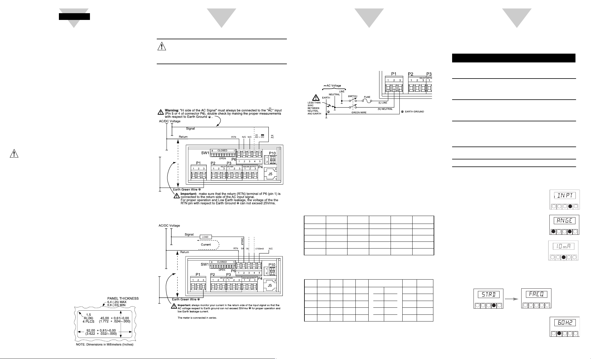
Wiring-Signal Source
1. Remove the panel at the back of the unit.
2. Locate the P6 connector.
3. Make sure the signal source is off.
4. Insert the correct wire in each terminal as shown in the
following figure and tighten the lockdown screws.
5. Tug gently on the wires to verify the connections.
For Voltage Meter
For Current Meter
Warning: Do not connect AC power to your device until you
have completed all input and output connections. This
device must only be installed by a specially trained
electrician with corresponding qualifications. Failure to
follow all instructions and warnings may result in injury!
Connect ac Power
1. Locate the P1 connector.
2. Insert the correct wire in each terminal as shown in the
following figure and tighten the lockdown screws.
3. Tug gently on the wires to verify the connections.
Turn On the Unit
1. Plug the unit into a properly grounded 115V power
supply.
The unit initializes, scrolling the following message on
the front panel: TRUE RMS VOLT or TRUE RMS
CURRENT. Then the present value should display.
2. Verify that a value is displayed. If not:
• Unplug the unit
• Verify the P1 power connections
• Check your power source
• Plug the unit in again
Set SW Switches (If Necessary)
Range Selections for Voltage Input
Range Selections for Current Input
Configure the Unit
To configure the meter, you use the buttons on the front
panel.
To: Take This Action:
Display the Main Press the MENU button. The
Configuration Menu first function on the menu,
(examples: INPT, RDNG) INPT, displays.
Select a level 2 item submenu Press the STPTS button
(Once main menu displays) followed by the MENU
(example of level 2 RNGE button.
under the INPT menu)
Select a level 3 submenu Press the /MIN button.
item (Once level 2 item Press the /MAX button
displays) (example of level 3 to scroll through level 3
is 10V under RNGE) selections.
Select a level 4 submenu* Press the /MAX button.
item (Once level 3 item
displays) (example of level 4
is 300 under BAUD under
COM.P (Communication Protocols)
Go back to the previous Press the RESET button.
menu function
Exit the Configuration Menu Press the RESET button twice.
* If applicable
Set Range,Frequency & Coupling
1. Press MENU until the meter displays:
2. Press SETPTS, followed by
MENU until the meter displays:
3. Press /MIN. The meter flashes the
input range. Press /MAX to scroll
through choices. Your choices are:
0.1V(1mA)*, 1V (10 mA)*, 10V (0.1A)*,
100V (1A)* and 750V (5A)*
*— items in parenthesis are for current meter only
4. Press MENU to select the input range shown. The
meter displays:
5. Press /MIN. The meter flashes the
current frequency setup.
Press /MAX to scroll through choices.
Your choices are: 50HZ, 60HZ or ALL.
Range
750V
100V
10V
1V
0.1V*
SW1-1 to
SW1-5
Open
Open
Open
Open
Open
SW1-6
Open
Closed
Closed
Closed
Open
SW1-7
Closed
Closed
Open
Open
Open
SW1-8
Open
Open
Closed
Open
Open
SW1-9
Closed
Open
Open
Open
Open
Open
== DC coupled
SW1-7 to
SW1-9
Open
Open
Open
Open
Open
Range SW1-5 SW1-6
SW1-1
SW1-2
SW1-3
SW1-4
Open
Open
Open
~ AC coupled
Open
Closed
Closed
Closed
Closed
Closed
5A Open
Open
Open
Open
Closed
1A Closed
Open
Open
Open
Open
100mA Closed
Closed
Open
Open
Open
10mA Closed
Open
Closed
Open
Open
1mA
Open
Open
Closed
Open Closed
/MAX
SETPTS
/MIN
SETPTS
/MAX
/MIN
SETPTS
/MAX
/MIN
RESET
MENU
SETPTS
RESET
MENU
MENU
SETPTS
/MAX
/MIN
RESET
MENU
/MAX
/MIN
RESET
MENU
/MAX
/MIN
SETPTS
MENU
RESET
RESET
 Loading...