

Page 1
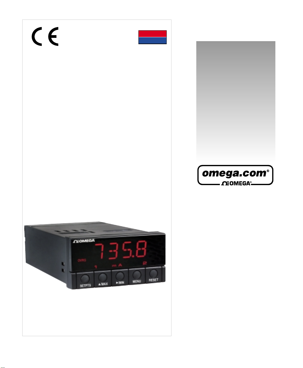
DP25-VRMS
DP25-CRMS
True RMS Meter
omega.com
e-mail: [email protected]
For latest product manuals:
omegamanual.info
User ’s Guide
Shop on line at
MADE IN
USA
Page 2

It is the policy of OMEGA to comply with all worldwide safety and EMC/EMI regulations that apply. OMEGAis constantly pursuing certification of its products to the European New
Approach Directives. OMEGA will add the CE mark to every appropriate device upon certification.
The information contained in this document is believed to be correct, but OMEGA Engineering, Inc. accepts no liability for any errors it contains, and reserves the right to alter
specifications without notice.
WARNING: These products are not designed for use in, and should not be used for, patient-connected applications.
This device is marked with the international caution symbol. It is important to read the Setup Guide before installing or commissioning this device as the guide contains important
information relating to safety and EMC.
This device is marked with the international caution symbol. It is important to read the Setup Guide before installing or commissioning this device as the guide contains
important information relating to safety and EMC.
!
®
®
OMEGAnet® On-Line Service
www.omega.com
Internet e-mail
Servicing North America:
USA: One Omega Drive, P.O. Box 4047
ISO 9001 Certified Stamford CT 06907-0047
Canada: 976 Bergar
Laval (Quebec) H7L 5A1
TEL: (514) 856-6928 FAX: (514) 856-6886
e-mail: [email protected]
For immediate technical or application assistance:
USA and Canada: Sales Service: 1-800-826-6342 / 1-800-TC-OMEGA
Customer Service: 1-800-622-2378 / 1-800-622-BEST
Engineering Service: 1-800-872-9436 / 1-800-USA-WHEN
Mexico and TEL: (001)800-TC-OMEGA® FAX: (001) 203-359-7807
Latin American: En Espa
ñol: (001) 203-359-7803
e-mail: [email protected]
®
®
®
Servicing Europe:
Czech Republic: Frystatska 184, 733 01 Karviná
Germany/Austria: Daimlerstrasse 26, D-75392 Deckenpfronn, Germany
TEL: +49 7056 9398-0 FAX: +49 7056 9398-29
Toll Free in Germany: 0800 639 7678
e-mail: [email protected]
United Kingdom: One Omega Drive
ISO 9002 Certified River Bend Technology Centre
Northbank, Irlam Manchester M44 5BD United Kingdom
TEL: +44 161 777 6611 FAX: +44 161 777 6622
Toll Free in England: 0800 488 488
e-mail: [email protected]
Page 3

i
C
ONTENTS
Section 1: Setup 1
1.1 Before You Begin 2
1.2 Features and Options 3
1.3 Safety Considerations 4
1.4 Getting Started 5
Section 2: Operation 13
2.1 Introduction 14
2.2 SW1 DIP Switch Positions for Input Ranges 15
2.3 Front Panel Display 16
2.4 Meter Buttons 17
2.5 Flow Charts 18
Setpoint Adjustment (Run Mode) 18
Menu Configuration (Configuration Mode) 19
2.6 Menu Configurations 21
Input Menu 22
Reading Menu 24
Setpoint Menu 29
Output Menu 32
Communication Menu 34
Section 3: True RMS Measurement 47
3.1 Introduction 48
3.2 True RMS versus Rectified-average Readings 49
3.3 Voltage-Divider Action of Leads and Meter Input Impedance 50
3.4 Input Current Effects 51
3.5 Overvoltage Heating 51
3.6 Guarding Against AC Pickup 51
3.7 Common-Mode Voltage Effects 52
Section 4: Defaults and Specifications 53
4.1 Back of the Meter 54
4.2 Main Board 56
4.3 W1–W3 Solder Jumpers 57
4.4 Signal Board 58
4.5 Meter Housing 60
4.6 Factory Default Values 61
4.7 Meter Specifications 62
4.8 Glossary 69
Section 5: CE Approvals Information 71
Page 4

L
IST OFFIGURES
Figure 1.1 Panel Cut-out Dimensions 5
Figure 1.2 Exploded View of the Meter 6
Figure 1.3 P6 Volt Meter Connection 7
Figure 1.4 P6 Current Meter Connection 8
Figure 1.4.1 P6 Current Meter Connection with Optional Current Transformer 8
Figure 1.5 P2 & P3 Dual Relay Output Connection 9
Figure 1.6 P4 Analog Output Connection 9
Figure 1.7 P10 & J5 RS232 Output Connections 10
Figure 1.8 J5 Half-duplex RS485 Output Connections 10
Figure 1.9 SW1 Input Range Selection 11
Figure 1.10 P1 AC Power Connection 12
Figure 2.1 Front Panel Display for Volt Meter 16
Figure 2.2 Front Panel Display for Current Meter 16
Figure 2.3 Flow Chart for Setpoint Configuration (Run Mode) 18
Figure 2.4 Flow Chart for Configuration Mode, Part 1 19
Figure 2.5 Flow Chart for Configuration Mode, Part 2 20
Figure 3.1 True RMS versus Rectified-average Readings 49
Figure 3.2 Approximate Input Resistance 50
Figure 4.1 Volt Meter Connections 54
Figure 4.2 Volt Meter Label 54
Figure 4.3 Current Meter Connections 55
Figure 4.4 Current Meter Label 55
Figure 4.5 Jumper Positions on the Main Board 56
Figure 4.6 W1–W3 Jumper Locations 57
Figure 4.7 Signal Board 58
Figure 4.8 Exploded View of Case and Board Assembly 59
Figure 4.9 Meter Housing and Panel Cut-out Dimensions 60
ii
Page 5

iii
L
IST OFTABLES
Table 1.1 RS232 Meter Connection to the Computer 10
Table 1.2 P1 AC Power Wire Color & Terminal Connections 12
Table 2.1 DIP Switch Positions for Voltage Meter 15
Table 2.2 DIP Switch Positions for Current Meter 15
Table 2.3 Display Indicators 16
Table 2.4 Button Functions 17
Table 2.5 Menu Descriptions 21
Table 3.1 Meter Net Loading Impedance 50
Table 4.1 Jumper Functions 56
Table 4.2 W1-W3 Jumper wiring 57
Table 4.3 Menu Item Defaults 61
Table 4.4 Analog Output Scale and Offset Defaults 61
Table 4.5 Signal Input Specifications 62
Table 4.6 Display Specifications 62
Table 4.7 Span Tempco for Voltmeter 63
Table 4.8 Span Tempco for Current Meter 63
Table 4.9 Analog to Digital Specifications 63
Table 4.10 Isolated Analog Output Specifications 64
Table 4.11 Communications Information 64
Table 4.12 Input Power Specifications 64
Table 4.13 Operating Environment 65
Table 4.14 Mechanical Specifications 65
Table 4.15 Alarm Outputs 65
Table 4.16 Voltage Model Accuracy (DC coupled inputs) 66
Table 4.17 Voltage Model Accuracy (AC coupled inputs) 66
Table 4.18 Current Model Accuracy 67
Table 4.19 Decimal Point & Unit of Measure Defaults 67
Table 4.20 Insulation 68
Page 6

P
REFACE
Preface to the Operator's Manual
The latest additions to the digital panel meter series are the VRMS and CRMS True RMS Volt /
Current meters. Both the VRMS (voltage meter) and the CRMS (current meter) may be ordered
with the isolated analog output, and/or dual relay option. These options are not field installable
and must be ordered at the time of purchase. The VRMS measures voltages from 100mV to
750V (see CE Approvals section for full details) in five ranges. All ranges are pre-calibrated and
selected via the rear dip switch. The CRMS can measure currents from 1mA to 5amp. The
current meter has an internal built in shunt for the 5amp range. The 5amp and the 1amp range
have dedicated inputs. The 1mA through 100mA ranges may be selected via the rear dip switch.
Again, the meter is shipped pre-calibrated for all the ranges. Users need only connect the meter
to the signal source and select the proper range from the menu. The meter will then start
measuring and displaying the voltage or current present at its inputs.
The RMS meters are ideal for monitoring complex voltage or current waveforms generated by
SCR banks to control the motor speed/torque. If the dual relay option is used, the meters can be
programmed to provide an alarm when the motor is overloaded or when the load is disengaged
from the motor.
Other typical applications would be to monitor the line voltage or current and use the isolated
analog output to transmit the information to a chart recorder. The meters can also communicate
with PLC's and computers via an optional isolated serial RS232 or RS485 board. This option may
be added at any time as it is field installable.
Range switching for both models is done by selecting the proper opened/closed position for the
SW1 DIP switches (see section 2.2) accessible from the back of the meter. Once the SW1
switches have been set to the desired voltage or current range, the same range must also be
selected from the Range (RNGE) submenu of the Input (INPT) main menu (see the menu section
2 configuration flowchart ).
You must decide whether the signal is to be AC or DC coupled. AC coupling is the preferred
method when the input signal is ridding on some undesirable DC voltage. To AC couple the
voltage
signal, connect the input signal to the P6 terminal labeled AC (see section 1.4.2), and
change the Coupling (CPLG) submenu of the Input (INPT) main menu to AC. To remove the DC
component of the current
signal, SW1-5 DIP switch must be opened (see section 2.2). If the
measurement is being done directly on the local power where the frequency may be 50Hz or
60Hz, set the Frequency (FREQ) submenu of the Input (INPT) main menu to the local power
frequency for increased accuracy. If the frequency of the input signal is not known, select ALL
from the Frequency (FREQ) submenu. The second part of this manual, Operation, explains
menu configuration in detail.
iv
Page 7
v
N
OTES
When rescaling the meter either with or without known loads, if a high
degree of accuracy is required, do not apply 0 volts or use 0 as a
reference point (see section 2.6.2). For any rescaling, the minimum
signal should always be 3 to 5% of the full scale of the signal range. The
same is true for scaling the analog output option. Do not use a value of 0
on the display if a high degree of accuracy is required, but instead use a
value slightly higher than 0 counts on the display.
NOTES, WARNINGS and CAUTIONS
Information that is especially important to note is identified by these labels:
• NOTE
• WARNING
• CAUTION
• IMPORTANT
NOTE: provides you with information that is important to successfully setup and
use the Programmable Digital Meter.
CAUTION: tells you about the risk of electric shock.
CAUTION, RISK OF DANGER: tells you of circumstances or practices that can
effect the meter's functionality and documentation needs to be consulted in all
cases, in order to find out the nature of potential hazards and actions.
Note
☞
Note
☞
Page 8

C
ONTENTS
vi
Page 9

S
ETUP
Section 1: Setup
Before You Begin
Features and Options
Safety Considerations
Getting Started
1
1
Page 10

1
S
ETUP
1.1 Before You Begin
If there are any questions about the shipment, use the phone number
for the Customer Service Department nearest you.
Remove the packing slip and verify that you have received everything
listed, including:
• True RMS Meter
• Operator's Manual
• Quick Start Pamphlet
• Connectors
!
Inspect the container and equipment for signs of damage as
soon as you receive the shipment. Note any evidence of rough
handling in transit. Immediately report any damage to the
shipping agent. The carrier will not honor damage claims unless
all shipping material is saved for inspection. After examining
and removing the contents, save the packing material and
carton in the event reshipment is necessary.
In addition to the meter and connectors, you will need the following
items to setup your unit:
• 110V three-prong power cord
• 1/8" flat head screwdriver
1.1.3 What You
Will Need
1.1.2 Inspecting
Your Shipment
1.1.1 Customer
Service
2
Page 11
3
S
ETUP
1.2 Features and Options
Your meter has several basic features, some of which are listed below.
For more detailed information on specifications and factory defaults, see
Section 4: Specifications.
• 4 Digit, 14 segment LED display
• NEMA 4 / Type 4 Front Bezel
• Peak and Valley detection
• Nonvolatile memory — no battery backup necessary
• 115Vac or 230Vac 50/60 Hz power source
There are two models available — a current meter and a volt meter.
Both of these models are available from the factory in the following
configurations:
• Basic Unit
• Basic Unit with Dual Relay Output
• Basic Unit with Isolated Analog Output
• Basic Unit with Dual Relay and Isolated Analog Output
The relay and analog outputs are not field installable options.
They must be requested at time of purchase. Menus will only be
available for those options that are supported by that meter.
The models can accommodate a communication board, which can be
installed at any time. There are two different communication boards
available:
• Isolated RS232 Output
• Isolated RS485 Output
If your meter has a communication board installed, then you
may control all functions of the meter through a serial
communications connection with your computer. The book,
Serial Communications, that comes with the communication
board itself, has detailed information on setup and configuration
procedures. Note that this manual, the Operator's Manual,
explains only the more basic options available to users whose
meters are equipped with the communication board.
Note
☞
1.2.3 Field
Installable
Options
Note
☞
1.2.2 Factory
Configurations
1.2.1 Basic
Features
1
Page 12
1
S
ETUP
1.3 Safety Considerations
This device is marked with the international caution symbol. It is important to read
this manual before installing or commissioning this device as it contains important
information relating to Safety and EMC (Electromagnetic Compatibility).
Unpacking & Inspection
Unpack the instrument and inspect for obvious shipping damage. Do not attempt to
operate the unit if damage is found.
This instrument is a panel mount device protected in accordance with EN 610101:2001, electrical safety requirements for electrical equipment for measurement,
control and laboratory. Installation of this instrument should be done by qualified
personnel. In order to ensure safe operation, the following instructions should be
followed.
This instrument has no power-on switch. An external switch or circuit-breaker shall
be included in the building installation as a disconnecting device. It shall be marked
to indicate this function, and it shall be in close proximity to the equipment within
easy reach of the operator. The switch or circuit-breaker shall not interrupt the
Protective Conductor (Earth wire), and it shall meet the relevant requirements of
IEC 947–1 and IEC 947-3 (International Electrotechnical Commission). The switch
shall not be incorporated in the mains supply cord.
Furthermore, to provide protection against excessive energy being drawn from the
mains supply in case of a fault in the equipment, an overcurrent protection device
shall be installed.
• The Protective Conductor must be connected for safety reasons. Check
that the power cable has the proper Earth wire, and it is properly connected. It is
not safe to operate this unit without the Protective Conductor Terminal
connected.
• Do not exceed voltage rating on the label located on the top of the instrument
housing.
• Always disconnect power before changing signal and power connections.
• Do not use this instrument on a work bench without its case for safety
reasons.
• Do not operate this instrument in flammable or explosive atmospheres.
• Do not expose this instrument to rain or moisture.
• Unit mounting should allow for adequate ventilation to ensure instrument does
not exceed operating temperature rating.
• Use electrical wires with adequate size to handle mechanical strain and power
requirements. Install without exposing bare wire outside the connector to
minimize electrical shock hazards.
EMC Considerations
• Whenever EMC is an issue, always use shielded cables.
• Never run signal and power wires in the same conduit.
• Use signal wire connections with twisted-pair cables.
• Install Ferrite Bead(s) on signal wires close to the instrument if EMC problems
persist.
4
Note
☞
Note
☞
Page 13
5
S
ETUP
1.4 Getting Started
Follow these steps to start using your meter right away:
• Mount the meter (section 1.4.1)
• Connect the signal source (section 1.4.2)
• Connect outputs (section 1.4.3)
• Set DIP switches for your input level (section 1.4.4)
• Connect the ~AC power cord to the meter (section 1.4.5)
• Turn on the meter (section 1.4.6)
1. Remove the rear cover at the back of the unit.
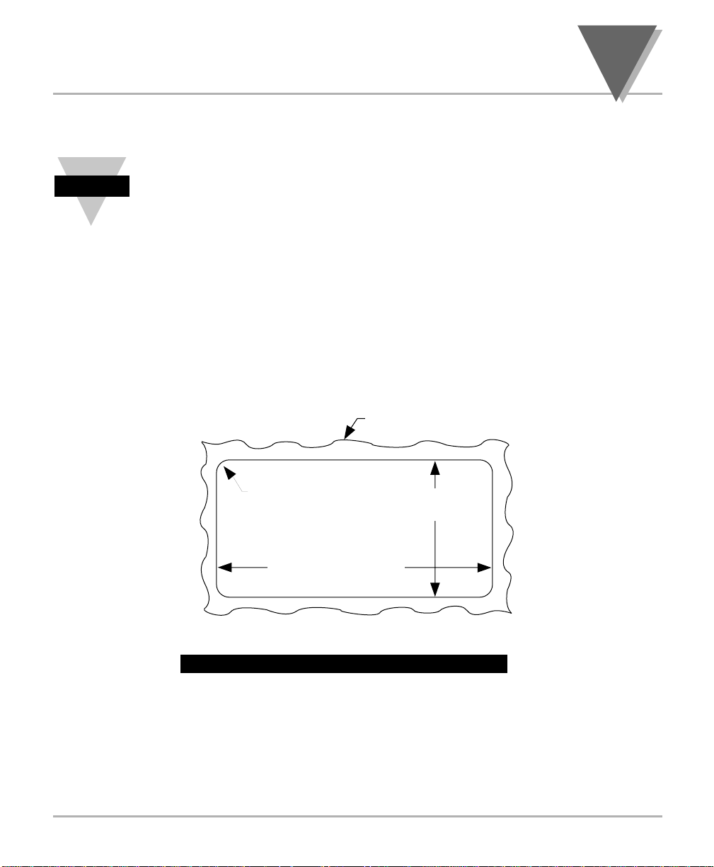
2. Cut a hole in your panel, as shown. (see Figure 1.1)
Figure 1.1 — Panel Cut-out Dimensions
1.4.1 Mount the
Meter
Overview
1
PANEL THICKNESS
6,4 (.25) MAX
0,8 (.03) MIN
1,5
R
(.06)
4 PLCS
92,00 + 0,81/–0,00
(3.622 + .032/–.000)
NOTE: Dimensions in Millimeters (Inches)
45,00 + 0,61/-0,00
(1.772 + .024/–.000)
Page 14
1
S
ETUP
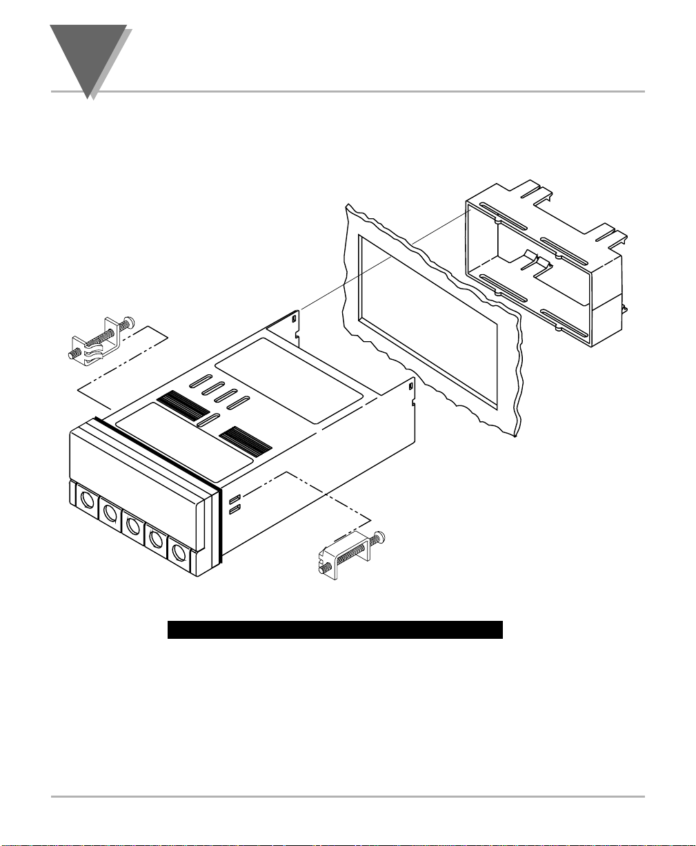
3. Insert the meter into the hole. Be sure the front bezel is flush to
your panel. (see Figure 1.2)
Figure 1.2 — Exploded View of the Meter
6
P
A
N
E
L
C
U
T
-O
U
T
CONNECTOR
LABEL
REAR COVER
(REMOVED)
"N
E
O
M
R
B
G
IN
T
N
U
T
E
K
C
A
E
L
Y
T
" S
W
PRODUCT
LABEL
FRONT BEZEL
GASKET
CASE
B
"O
L
O
M
C
A
R
G
IN
T
N
U
E
K
S
C
P
2
T
E
L
Y
T
" S
R
E
D
Page 15
7
S
ETUP
1
1.4.2 Connect
Signal Source
!
WARNING: Do not connect ac power to your meter until you have completed all
input and output connections. Failure to do so may result in injury!
!
IMPORTANT: This device must only be installed electrically by specially trained
electrician with corresponding qualifications. The mains power input to the unit as
well as the AC input signal to be measured must agree with the wiring instruction.
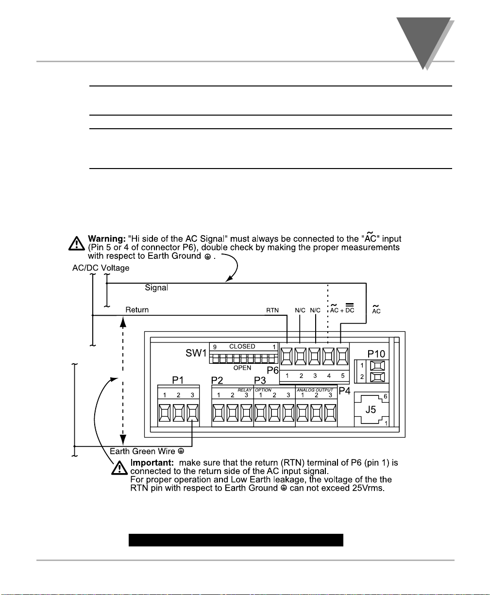
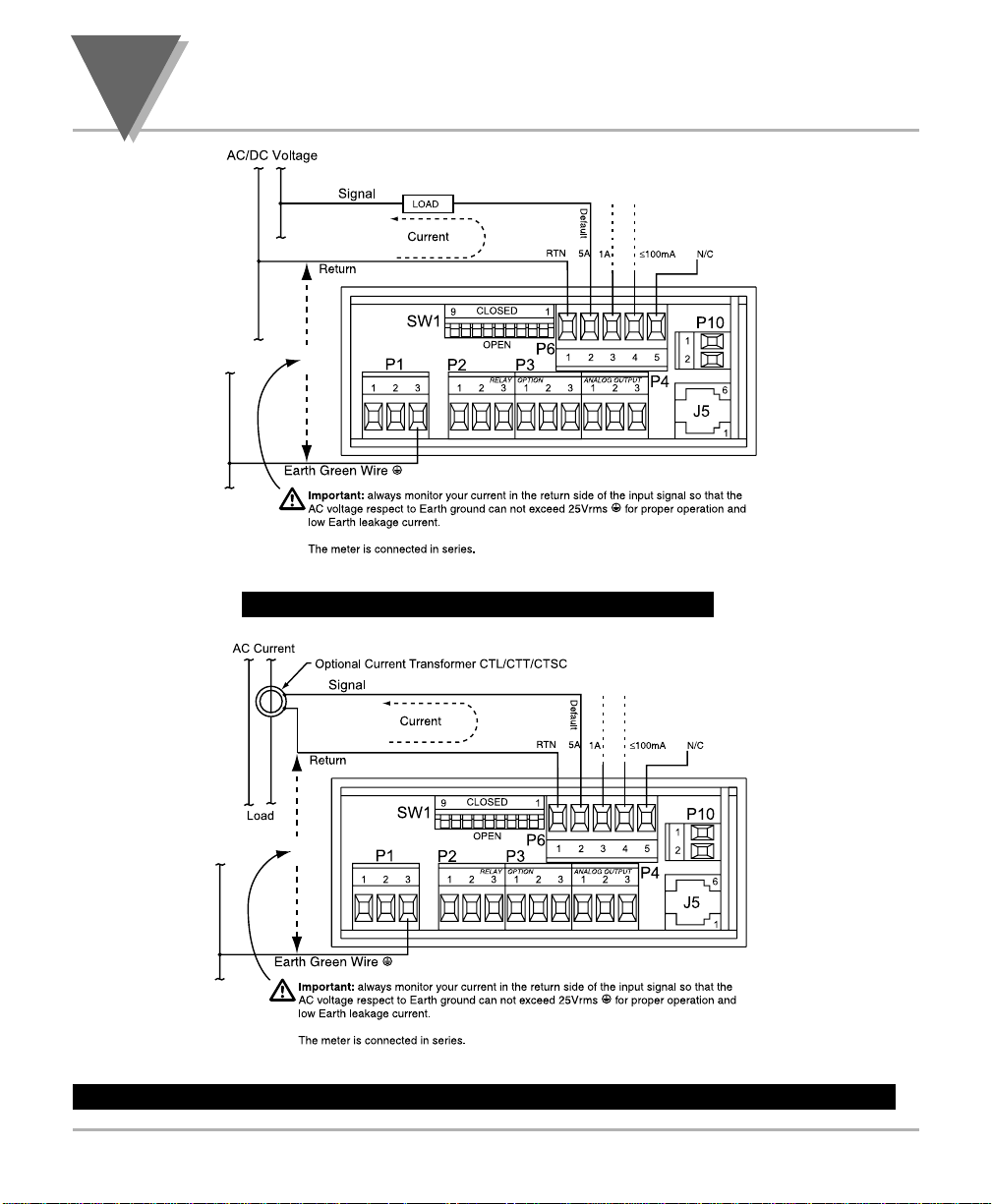
1. Locate the P6 connector. (see Figures 1.3 and 1.4)
2. Make sure the signal source is off.
3. Insert the correct wire in each terminal and tighten the lockdown screw. Tug
gently on the wires to verify that the connections are secure.
Measurement Category II. Rated Maximum Working Voltage: 300 Vac/dc. No CE compliance
from 300V - 750V. See CE Approvals section for more details.
Figure 1.3 — P6 Volt Meter Connection
Page 16
1
S
ETUP
Measurement Category II. Rated Maximum Working Current: 5A.
Figure 1.4 — P6 Current Meter Connection
Measurement Category II. Rated Maximum Working Current: 5A.
Figure 1.4.1 - P6 Current Meter Connection with Optional Current Transformer
8
Page 17
9
S
ETUP
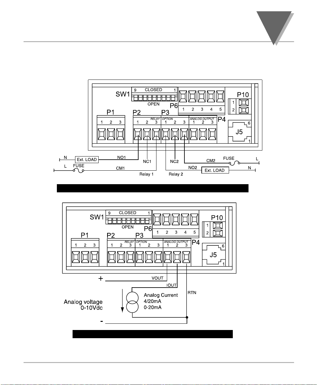
Your meter may have one or more factory installed outputs. The Dual
Relay Output Connection and the Analog Output Connection are shown
below. (see Figures 1.5 and 1.6)
Figure 1.5 — P2 & P3 Dual Relay Output Connection
Figure 1.6 — P4 Analog Output Connection
1.4.3 Connect
Outputs
1
Page 18
1
S
ETUP
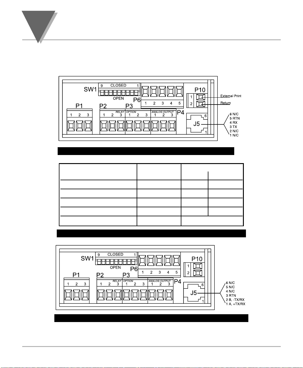
Your meter may also have one of two field installable communication
outputs — either a RS232 or RS485 Output Connection. (see Figures
1.7 and 1.8)
Figure 1.7 — P10 & J5 RS232 Output Connections
Table 1.1 — RS232 Meter Connection to the Computer
Figure 1.8 — J5 Half-duplex RS485 Output Connections
Meter (DCE) Computer (DTE)
Pin Signal / Function RJ12 D9 D25
RTS, meter from computer 2 7 4
TX, meter = RX, computer 3 2 3
RX, meter = TX, computer 4 3 2
GND 5 5 7
NC (not connected) 1,6 (all others)
10
Page 19
11
S
ETUP
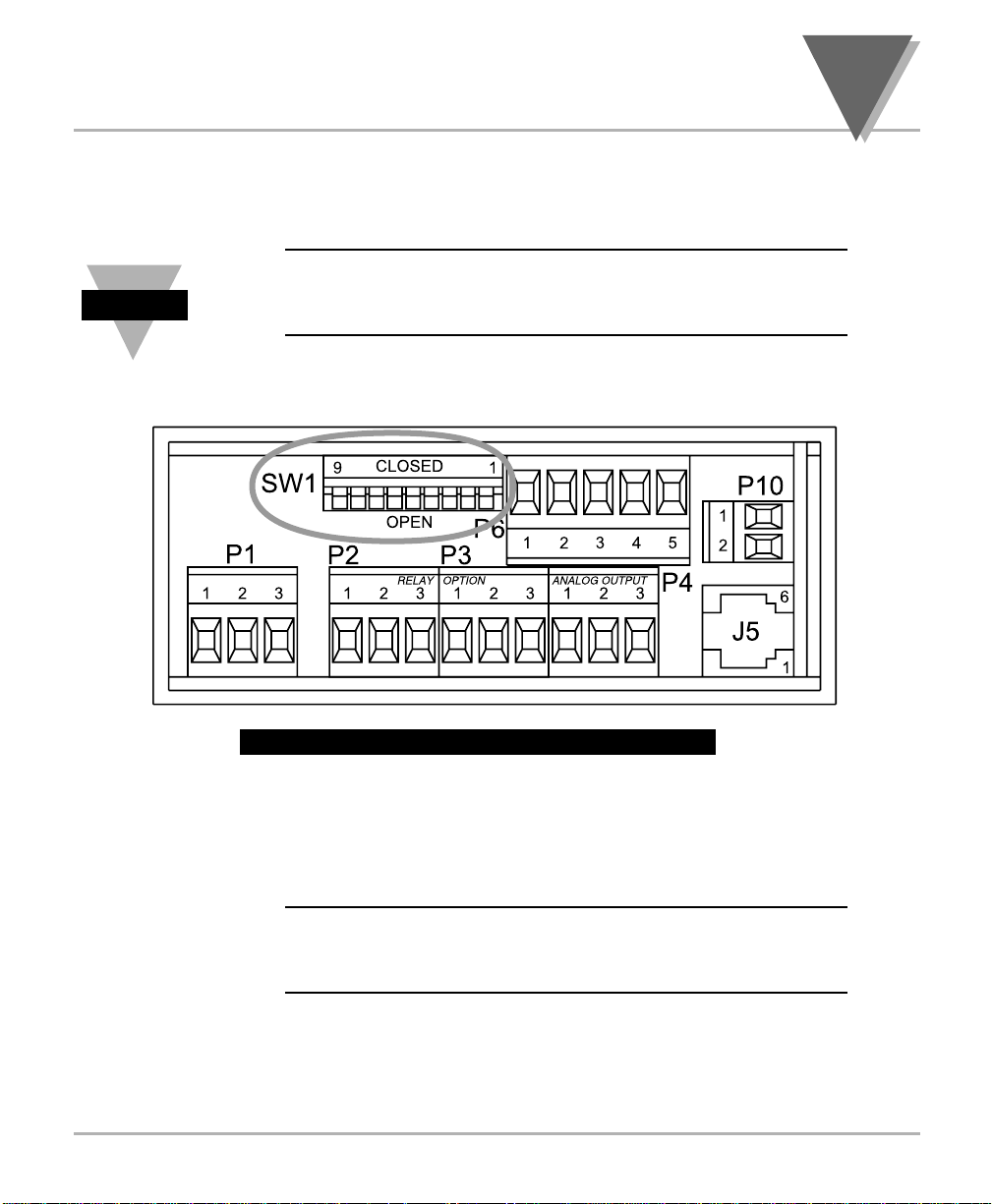
Locate the SW1 DIP switch on the back of the meter. (see Figure 1.9)
To select an input range, SW1-1 through SW1-9 must be in the correct
position.
Please refer to the tables on page 16 for the switch positions
that match your desired input range. Note that you must also
configure the Input menu to reflect your desired input range.
Figure 1.9 — SW1 Input Range Selection
1. Remove the panel at the back of the meter.
2. Locate the P1 connector. (see Figure 1.10)
!
WARNING: Do not connect AC power to your meter until all
input and output connections have been properly established.
Failure to do so may result in injury.
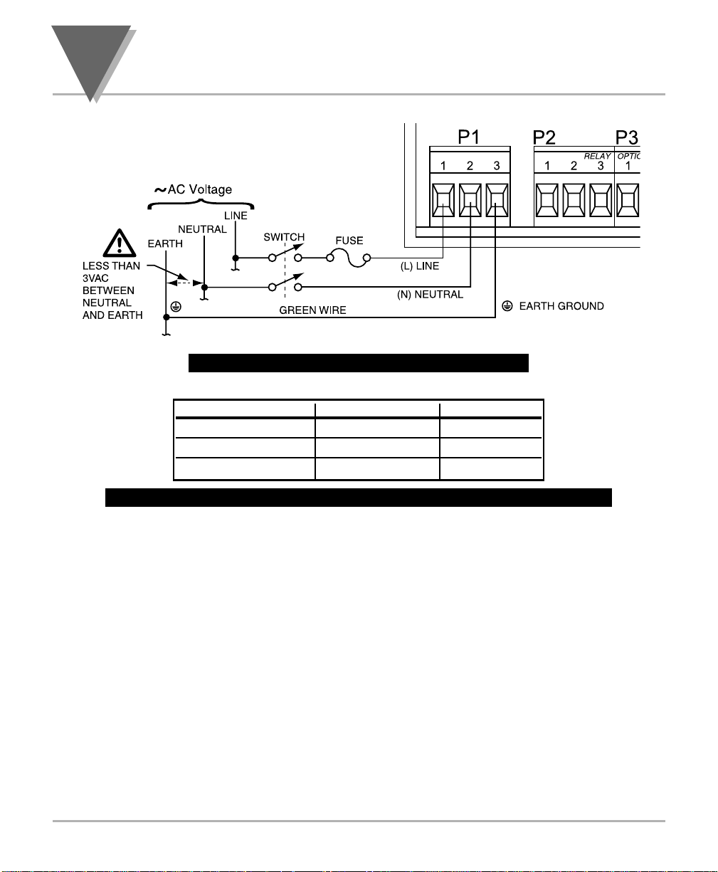
3. Insert the correct wire in each terminal and tighten the lockdown
screw. See Table 1.2, for wire color definitions. Tug gently on the
wires to verify that the connections are secure.
1.4.5 Connect the
AC Power Cord to
the Meter
1.4.4 Set DIP
Switches
1
Note
☞
Page 20
1
S
ETUP
Figure 1.10 — P1 AC Power Connection
Table 1.2 — P1 AC Power Wire Color & Terminal Connections
1. Plug the unit into a properly grounded 115V power supply. The unit
will initialize, scrolling one of the following messages on the front
panel:
TRUE…RMS…VOLT…VER.X
TRUE…RMS…CURRENT…VER.X
X = the version number
2. The present value should then display. If a value does not display,
follow these steps:
• Unplug the unit
• Verify the P1 power connections
• Check your power source
• Plug the unit in again
1.4.6 Turn On the
Meter
CONNECTION EUROPE USA
AC-Line Brown Black
AC-Neutral Blue White
AC-Earth Ground Green/Yellow Green
12
Page 21

13
O
PERATION
Section 2: Operation
Introduction
SW1 DIP Switch Positions
Front Panel Display
Meter Buttons
Flow Charts
Menu Configurations
2
Page 22
2
O
PERATION
2.1 Introduction
The meter has two different modes of operation. The first, Run Mode, is
used to display values for setpoint 1 and setpoint 2 and display or clear
peak and valley values. The other mode, Configuration Mode, is used to
navigate through the menus options and configure the meter.
This section of the manual, Operation, will explain both the
Run Mode and the Configuration Mode and is divided into the
following sections:
• SW1 DIP Switch Positions (Section 2.2)
• Front Panel Display (Section 2.3)
• Meter Buttons (Section 2.4)
• Menu Flow Charts (Section 2.5)
• Menu Configurations (Section 2.6)
There are two meter models available — a current meter and a
volt meter. Both of these models are available from the factory
in the following configurations:
• Basic Unit
• Basic Unit with Dual Relay Output
• Basic Unit with Isolated Analog Output
• Basic Unit with Dual Relay and Analog Output
The relay and analog outputs are not field installable options.
They must be requested at time of purchase. Menus will only
be available for those options that are supported by that meter.
Note
☞
Overview
14
Page 23
15
O
PERATION
2.2 SW1 DIP Switch Positions for Input Ranges
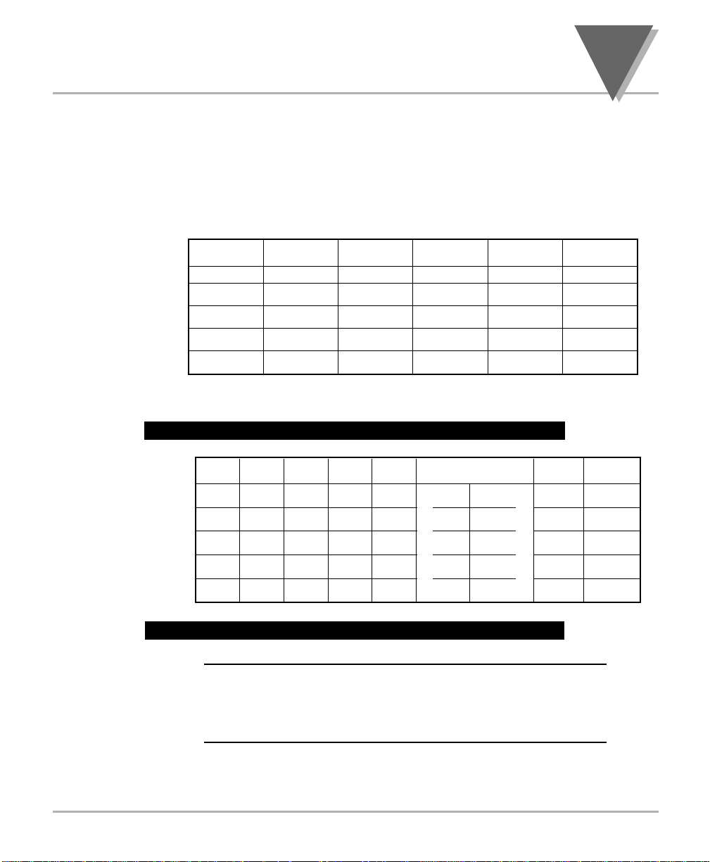
Before you change the input range of the meter, set the SW1 DIP
switches to the correct positions. These switches are located at the
back of the meter. Refer to the following tables for the volt meter and
current meter settings.
* This range is fully calibrated only when ordered as an FS option.
Otherwise only a coarse calibration ± 2% applies.
Table 2.1 — DIP Switch Positions for Voltage Meter
Table 2.2 — DIP Switch Positions for Current Meter
!
WARNING:The 5 Amp and 1 Amp ranges have dedicated
inputs. You must always choose the input connector that
corresponds to your input range. Failure to do so may
result in injury!
2.2.2 Adjusting
SW1 DIP Switches
for Current Meter
2.2.1 Adjusting
SW1 DIP Switches
for Volt Meter
2
Range
750V
100V
10V
1V
0.1V*
SW1-1 to
SW1-5
Open
Open
Open
Open
Open
SW1-6
Open
Closed
Closed
Closed
Open
SW1-7
Closed
Closed
Open
Open
Open
SW1-8
Open
Open
Closed
Open
Open
SW1-9
Closed
Open
Open
Open
Open
SW1-7 to
Open
Open
Open
Open
Open
Closed
SW1-4
Closed
Open
Open
Open
Open Closed
~ AC coupled
Open
Open
Open
Open
Closed
Closed
Closed
Closed
Closed
== DC coupled
SW1-1
Range SW1-5 SW1-6
5A Open
1A Closed
100mA Closed
10mA Closed
1mA
SW1-2
Open
Open
Closed
Open
Open
SW1-3
Open
Open
Open
Closed
Open
SW1-9
Open
Open
Open
Open
Open
Page 24
2
O
PERATION
2.3 Front Panel Display
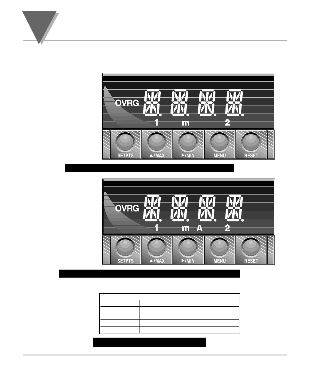
Figure 2.1 — Front Panel Display for Volt Meter
Figure 2.2 — Front Panel Display for Current Meter
Table 2.3 — Display Indicators
These indicators light when appropriate:
1 Setpoint 1 indicator
2 Setpoint 2 indicator
mA, A Milliamp, Amp for Current Meter
mV, V Millivolt, Volt for Voltmeter
OVRG Overflow indicator
2.3.3 Indicators
2.3.2 Current Meter
Display
2.3.1 Volt Meter
Display
16
V
Page 25
17
O
PERATION
2.4 Meter Buttons
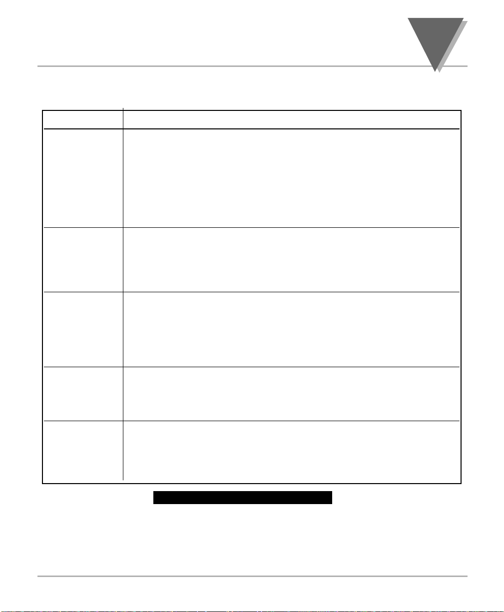
Table 2.4 — Button Functions
BUTTON DESCRIPTION
SETPTS In Run Mode press this button to display the values for setpoint 1 and
setpoint 2. Press this button repeatedly to recall the previous setpoint
settings. After using the /MAX and /MIN buttons to alter these
settings, press this button again to store the new values. (Unless you
press this button within 20 seconds to store your input, the meter will
scroll to setpoint 2 and retain the last value stored.)
In Configuration Mode press this button at the level 1 menus only
followed by MENU to enter into the level 2 menus.
/MAX In Run Mode press this button to recall the peak reading since the last
time the reset button was pressed. Press this button again to return to the
current readings without resetting the peak reading.
In Configuration Mode press this button to access Level 4 menu items,
then press the /MIN button to scroll through Level 4 menu items.
/MIN In Run Mode press this button to recall the valley reading since the last
time the reset button was pressed. Press this button again to return to the
current readings without resetting the valley reading.
In Configuration Mode press this button to access Level 3 menu items.
When configuring setpoint values, press this button to scroll to the next
digit.
MENU In Run Mode press this button to end the current measuring process and
enter configuration mode.
In Configuration Mode pressing this button will store your selections and
then advance you to the next menu item.
RESET In Run Mode press MENU button, followed by RESET button to reset
the latched alarms. (If your meter has this option).
In Configuration Mode press this button to go back to the previous
menu item. Press this button twice to exit the configuration
2
Page 26
2
O
PERATION
18
2.5 Flow Charts
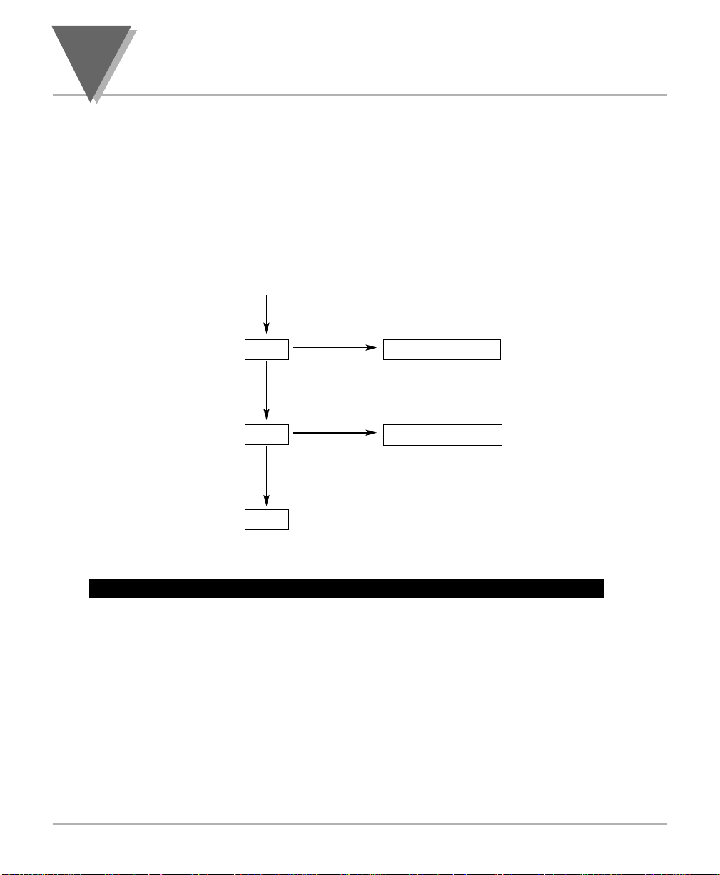
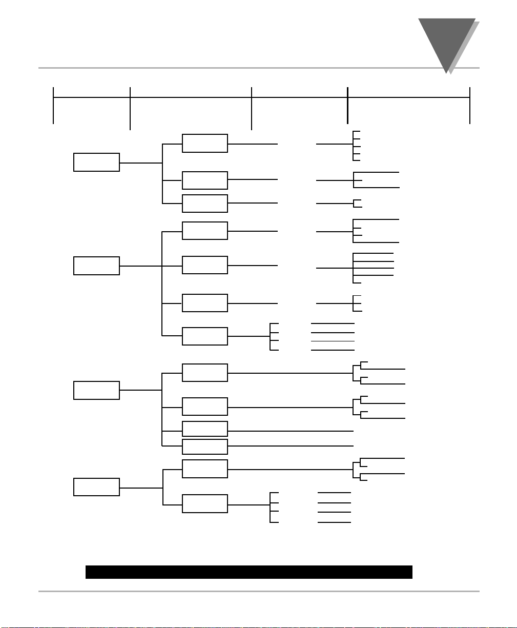
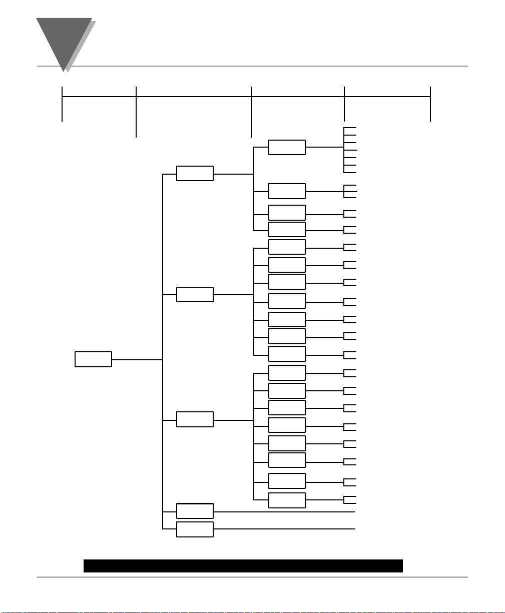
The following flow charts list all of the menus, submenus, and their
respective ranges. The first flow chart demonstrates how to adjust
setpoints while in Run Mode. The second and third charts contains all of
the menus available while in Configuration Mode. (The third chart is
only for those meters that have a communication board installed.)
Figure 2.3 — Flow Chart for Setpoint Configuration (Run Mode)
press
SETPTS
SP1
-199to9999
press /MAX until the desired value
is displayed, then
press /MIN to advance to the next digit
SP2
-199to9999
RUN
2.5.1 Setpoints and
Menu Configuration
Flow Charts
Page 27
19
O
PERATION
2
Figure 2.4 — Flow Chart for Configuration Mode, Part 1
AC for volt meter
DC
IN 1
RD 1
IN 2
RD 2
0.1V
1V
10V
100V
750V
or 1mA
or 10mA
or 0.1A
or 1A
or 5A
or
or
or
INPT
F.FFF
FF.FF
FFF.F
FFFF.
64
16
0
4
8
RDNG
mV
VA
mA
* TO SWITCH BETWEEN FIELDS PRESS
ITEMS MARKED WITH “
†” OR APPEARING IN PARENTHESIS ARE DEFAULT VALUES
60Hz
50Hz
ALL
-- --
-1999 - 9999 (9999)
-1999 - 9999 (0)
-1999 - 9999 (0)
-1999 - 9999 (9999)
/MIN
/MIN
/MIN
/MIN
/MIN
/MIN
/MIN
MENU LEVEL 1 MENU LEVEL 2 MENU LEVEL 3 MENU LEVEL 4
PRESS PRESS SETPTS ONCE
PRESS
PRESS
/MIN
/MAX
MENU
THEN PRESS MENU
FOR EACH LEVEL 1 ITEM
†
†
†
††
†
for current meter
†
for volt meter
†
for current meter
†
†
RD.S.O.
RNGE
DEC.P
CPLG
FLTR
UNIT
FREQ
ABOV
BELO
NORM
LTCH
LTCH
NORM
BELO
ABOV
SP.CF
0 - 9999 (3 count)
0 - 9999 (3 count)
PROG
DFLT
CURR
VOLT
OUT
OUT2
RD 2
OUT1
RD 1 -1999 - 9999
0 to 10.00V or 0 to 20.00mA
-1999 - 9999
0 to 10.00V or 0 to 20.00mA
*
*
*
*
*
*
†
†
†
†
†
†
SPT.1
SPT.2
S1.DB
S2.DB
OT.CF
OT.S.O.
Page 28
2
O
PERATION
20
Figure 2.5 — Flow Chart for Configuration Mode, Part 2
300
600
1200
2400
4800
9600
†
19.2K
NO
ODD
†
EVEN
NEW.P
†
M.BUS
CMD
†
CONT
PRTY
DATA
STOP
PROT
MODE
C.SUM
YES
NO
†
ECHO
LF
SPACE †
CR
SEPR
BAUD
STND
485
232C
†
NO
YES
†
YES
NO
†
NO
YES
†
YES
NO
†
PEAK
NO †
YES
STAT
RDNG
TIME
VALY
YES
NO
†
DATE
NO †
YES
YES
NO
†
NO †
YES
YES
NO
ID
UNIT
0 - 199 (-01)
0 - 9999 SEC. (1)
COMM
1BIT †
2BIT
7BIT †
8BIT
COMP
BUS.F
DAT.F
TX.TI
ADDR
MENU LEVEL 1 MENU LEVEL 2 MENU LEVEL 3 MENU LEVEL 4
PRESS PRESS SETPTS ONCE
PRESS
PRESS
/MIN
/MAX
MENU
THEN PRESS MENU
FOR EACH LEVEL 1 ITEM
ITEMS MARKED WITH “
†” OR APPEARING IN PARENTHESIS ARE DEFAULT VALUES
Page 29
21
O
PERATION
2.6 Menu Configurations
Both meters have at least two main menus — Input and Reading. If
your meter includes the Dual Relay capability, then it will have a
Setpoint Configuration menu. If your meter includes the Analog
Output capability, then it will have an Output menu. If your meter has
the optional communications board installed, then it will have a
Communication Configuration menu. Each of these main menus has
submenus.
Menu Name Description
INPT From the Input menu and its submenus you may
choose the range, frequency, and input coupling.
RDNG From the Reading menu and its submenus you may
select decimal point position, filter time constant, display
the unit of measure, and adjust the reading scale and
offset.
SP.CF From the Setpoint Configuration menu and its
submenus you may specify the active above/below or
normal/latch for the alarms and their corresponding dead
band.
OUT From the Output menu and its submenus you may
choose analog out for current mode or voltage mode
and you may adjust the output levels appropriate to
your application.
COMM From the Communication Configuration menu and its
submenus you may set the communications parameters
for digital output.
Table 2.5 — Menu Descriptions
The following pages will show, step by step, how to configure all
of the menus for your particular application. You may wish to
refer to the flow charts on the previous two pages while
configuring the menus.
Overview
2
Page 30
2
O
PERATION
2.6.1.0 INPUT MENU
From this menu you may choose the electrical range, frequency, and
input coupling. Follow these steps:
1. Press MENU until the meter displays:
INPT
2. Press SETPTS, followed by MENU until the meter displays:
RNGE
2.6.1.1 Input Menu: Electrical Range
Before selecting a range other than the default range of 750V (5A),
refer to the Tables in Section 2.2. to set the SW1 DIP switches. To
select an input range, follow these steps.
3. Press /MIN. The meter flashes the input range. Press /MAX to
scroll through these choices until you find the range that suits your
application: Note that there are default decimal point positions
and units of measure associated with each selected range. If
you change the input range, those two items will be updated
automatically according to Section 4.7.15, in Table 4.19. Note that
at any time you can change the decimal point position and or
the unit of measure to any position or value you want.
volt meter current meter
0-1V 1 mA
1V 10mA
10V 0.1 A
100V 1 A
750V 5 A
4. Press MENU to select the input range shown. After storing this
setting, the meter displays:
FREQ
INPT
RNGE
INPT
22
Page 31
23
O
PERATION
2.6.1.2 Input Menu: Electrical Frequency
To select an electrical frequency, follow these steps. The factory default
for electrical frequency is 60Hz if the meter is powered from a 100V
power source and 50Hz if the meter is powered from a 220V power
source.
5. Press /MIN. The meter flashes the current frequency selection.
Press /MAX to scroll through these choices:
60HZ 110V Power
50HZ 220V Power
ALL select if the signal frequency is not the
same as the power frequency
6. Press MENU to select the frequency shown. After storing this
setting, the meter displays:
CPLG
2.6.1.3 Input Menu: Coupling
To select AC or DC Coupling, follow these steps. The factory default is
AC. Note that volt meters have two different inputs for AC and DC
coupling. Current meters have only DC coupling. To AC couple the
current meter, SW1-5 DIP should be open. (See Table 2.2)
7. Press /MIN. The meter flashes the existing coupling selection.
Press /MAX to toggle between these choices:
AC measures only AC component of the input
signal
DC measures AC and DC component of the
input signal.
8. Press MENU to select the coupling shown. After storing this setting,
the meter displays:
RDNG
INPT
CPLG
INPT
FREQ
2
Page 32
2
O
PERATION
2.6.2.0 Reading Menu
From this menu you may choose the decimal point position, filter time
constant, display unit of measure, and adjust reading scale and offset.
1. Press SETPTS, followed by MENU until the meter displays:
DEC.P
2.6.2.1 Reading Menu:
Decimal Point Position
To select the decimal point location, follow these steps. FFF.F is the
factory default.
2. Press /MIN. The meter flashes the current decimal point position.
Press /MAX to scroll through these choices:
F.FFF FF.FF FFF.F FFFF.
3. Press MENU to select the decimal point location shown. After
storing this setting, the meter displays:
FLTR
2.6.2.2 Reading Menu:
Filter Value
To select a filter value, follow these steps. The factory default is 64.
4. Press /MIN. The meter flashes the filter value. Press /MAX to
scroll through these choices:
0 4 8 16 64
5. Press MENU to select the filter value location shown. After storing
this setting, the meter displays:
UNIT
RDNG
FLTR
RDNG
DEC.P
RDNG
24
Page 33
25
O
PERATION
2.6.2.3 Reading Menu:
Unit Value
To select a unit value, follow these steps. The factory default is V for
volt meters and A for current meters.
6. Press /MIN. The meter flashes the unit value.
Press /MAX to scroll through these choices:
volt meter current meter
——
(blank)
VA
mVmA
7. Press MENU to select the unit value location shown. After storing
this setting, the meter displays:
RD.S.O.
2.6.2.4 Reading Menu:
Reading Scale and Offset
This step is generally not required since the meters are precalibrated for
all ranges. Rescale only if the desired display is different than the actual
voltage or current being measured. Typically, this step would apply only
to the 5A or 100mV range.
To scale the meter to show readings in engineering units follow these
steps. There are two different methods. One method is on-line scaling.
The other method is manual scaling. On-line scaling will be described
first.
ON-LINE SCALING — This is the most common method since the
meter will display actual input from which you may determine the value
to be displayed.
1. Set the SW1 DIP Switch Positions if necessary.
Before you begin this procedure, you must set the SW1 DIP
switches to the correct positions. Failure to do so may result in
an incorrect reading. The SW1 DIP switches are located at the
back of the meter. For voltage and current input SW1 switch
positions, refer to the appropriate Table in Section 2.2. For best
resolution, find the maximum signal that will be applied to the meter.
Note
☞
RDNG
UNIT
2
RDNG
RD.S.O.
on-line
scaling
Page 34
2
O
PERATION
26
2. Set decimal point position if necessary.
The decimal point if configurable under the first
submenu of the Reading menu.
3. Press the MENU button, if necessary, until the meter
shows:
RD.S.O
4. Press the /MIN button. The meter shows:
IN 1
5. Press the /MIN button to show the existing value at
Input 1, with the fourth digit flashing.
6. Apply the low value at the input and press the /MIN
button again to show the actual value at the input
without a flashing digit. Wait until the value has settled.
Do not apply zero.
7. Press the MENU button. The meter shows:
RD 1
8. Press the /MIN button to show the existing value of
Display Reading for Input 1, with the fourth digit
flashing.
9. Press the /MIN and /MAX buttons to enter the
desired Display Reading for Input 1.
10. Press the MENU button. The meter shows:
IN 2
11. Press the /MIN button to show the existing value at
Input 2, with the fourth digit flashing.
12. Apply the second value at the input and press the
/MIN button again to show the actual value at the
input without a flashing digit. Wait until the value has
settled.
13. Press the MENU button. The meter shows:
RD 2
14. Press the /MIN button to show the existing value of
Display Reading for Input 2, with the fourth digit
flashing.
15. Press the
/MIN and /MAX buttons to enter the
desired Display Reading for Input 2
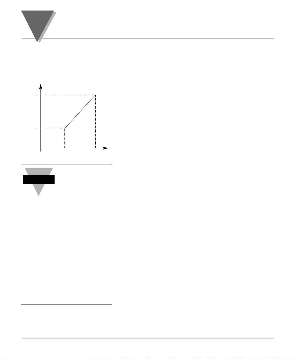
RD 2
IN 1 IN 2
Read 1
Read 2
Input 1 Input 2
Display Reading versus Input Signal
Display
Reading
RD 1
Input
Signal
When rescaling the
meter either with or
without known
loads, if a high
degree of accuracy
is required, do not
apply 0 volts or use
0 as a reference
point.
For any rescaling, the minimum
signal should always be 3 to 5%
of the full scale of the signal
range. The same is true for
scaling the analog output option.
Do not use a value of 0 on the
display if a high degree of
accuracy is required, but instead
use a value slightly higher than 0
counts on the display.
Note
☞
Page 35

27
O
PERATION
16. Press MENU to store the values. After storing these settings, the
meter will display one of four items.
If your meter is equipped with a Dual Relay capabilities, then your
meter will now display:
SP.CF GO TO 2.6.3.0 SETPOINT MENU
If your meter does not support Dual Relay capabilities, but has
Analog Output capabilities, then you are may skip the next section
concerning Dual Relay Output and proceed to the section
concerning the Analog Output Menu. Your meter will now display:
OUT SKIP NEXT MENU ITEM AND GO TO
2.6.4.0 OUTPUT MENU
If your meter does not support Dual Relay capabilities or Analog
Output capabilities, but has the communications board option
installed, then you are may skip the next two sections concerning
Dual Relay Output and Analog Output. Proceed to the section
concerning the Communications Menu. Your meter will now display:
COMM SKIP NEXT TWO MENU ITEMS AND GO
TO 2.6.5.0 COMMUNICATIONS MENU
If your meter is not equipped with Dual Relay or Analog Output
capabilities and does not have a communications board option
installed, then you are finished configuring your meter. It will now
display:
RUN if no values were changed
RST if values were changed
METER CONFIGURATION IS COMPLETE
2
Page 36

2
O
PERATION
MANUAL SCALING — This is used when you want to enter the
values for Input 1 (IN1) and Input 2 (IN2) as well as the Display
Readings for Input 1 (RD1) and Input 2 (RD2) manually.
1 Press the /MIN button. The meter shows:
IN 1
2. Press the /MIN button to show the existing value at Input 1, with
the fourth digit flashing.
3. Press the /MAX button.
4. Press the /MIN and /MAX buttons to enter the desired value for
Input 1.
5. Press the MENU button. The meter shows:
RD 1
6. Press the /MIN button to show the existing value of Display
Reading for Input 1, with the fourth digit flashing.
7. Press the /MIN and /MAX buttons to enter the desired Display
Reading for Input 1.
8. Press the MENU button. The meter shows:
IN 2
9. Press the /MIN button to show the existing value at Input 2, with
the fourth digit flashing.
10. Press the /MAX button.
11. Press the /MIN and /MAX buttons to enter the desired value for
Input 2.
12. Press the MENU button. The meter shows:
RD 2
13. Press the /MIN button to show the existing value of Display
Reading for Input 2, with the fourth digit flashing.
14. Press the /MIN and /MAX buttons to enter the desired Display
Reading for Input 2.
15. Press MENU to store the values. After storing these settings, the
meter will display one of four items.
If your meter is equipped with a Dual Relay capabilities, then
your meter will now display:
SP.CF go to 2.6.3.0 SETPOINT menu
RDNG
RD.S.O.
manual
scaling
28
Page 37
29
O
PERATION
If your meter does not support Dual Relay capabilities, but has Analog
Output capabilities, then you are may skip the next section concerning
Dual Relay Output and proceed to the section concerning the Analog
Output Menu. Your meter will now display:
OUT skip next menu item and go to
2.6.4.0 Output menu
If your meter does not support Dual Relay capabilities or Analog Output
capabilities, but has the communications board option installed, then
you are may skip the next two sections concerning Dual Relay Output
and Analog Output. Proceed to the section concerning the
Communications Menu. Your meter will now display:
COMM GO TO 2.6.5.0
COMMUNICATIONS MENU
If your meter is not equipped with Dual Relay or Analog Output
capabilities and does not have a communications board option installed,
then you are finished configuring your meter. It will now display:
RUN if no values were changed
RST if values were changed
meter configuration is complete
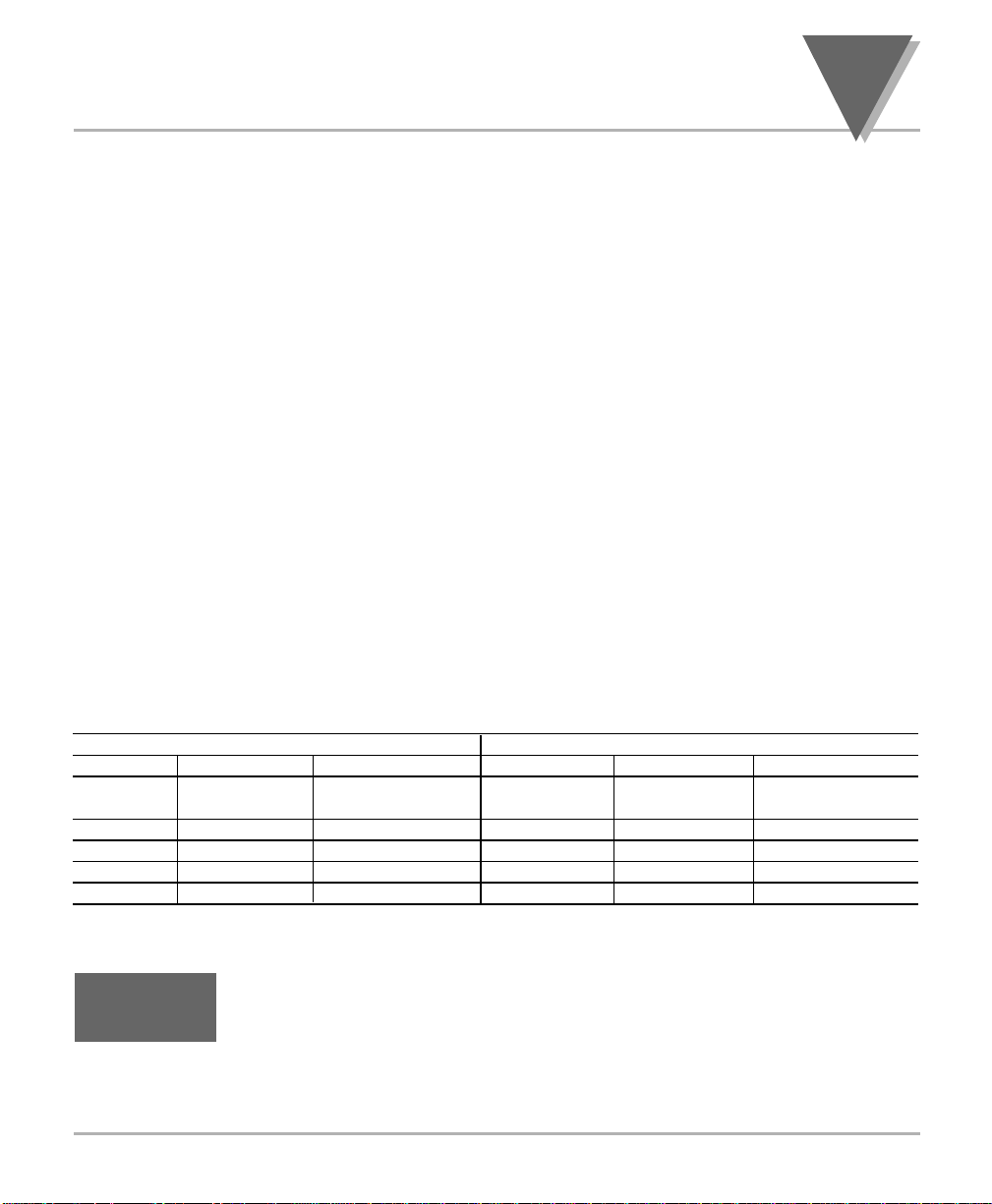
GAIN MULTIPLIER TABLE
CURRENT MODEL VOLTAGE MODEL
RANGE MULTIPLIER TOTAL COUNTS RANGE MULTIPLIER TOTAL COUNTS
5 A 1,000 cts/A 10,000 or 9999 750 V 10 cts/V 10,000 or 9999
(10 A f.s.) (1,000 V f.s.)
1 A 10,000 cts/A 100 V 100 cts/V
100 mA 100 cts/mA 10 V 1,000 cts/V
10 mA 1,000 cts/mA 1 V 10,000 cts/V
1 mA 10,000 cts/mA 0.1 V 100 cts/mV
2.6.3.0 Setpoint Menu:
This menu is only available for meters equipped with the Dual
Relay Output option. From this menu you may set the active band,
alarm zones, and deadband values for both setpoints.
1. Press SETPTS, followed by MENU until the meter displays:
SPT.1
SP.CF
2
Page 38
2
O
PERATION
2.6.3.1 Setpoint Menu:
Setpoint 1 — Band & Alarm
To set the active band and alarm zone for setpoint 1, follow these steps.
The ABOV active band position sets the band above the setpoint and
BELO sets it below the setpoint. The NORM alarm position indicates the
alarm is unlatched. The LTCH alarm position indicates the alarm has to
be reset if it is energized.
2. Press
/MIN. The meter flashes the last saved active band
position. Press
/MAX to toggle between these choices:
ABOV BELO
3. Press /MIN. The meter flashes the last saved alarm position.
Press
/MAX to toggle between these choices:
NORM LTCH
4. Press MENU to save the active band and alarm position. After
storing these settings, the meter displays:
SPT.2
2.6.3.2 Setpoint Menu:
Setpoint 2 — Band & Alarm
To set the active band and alarm zone for setpoint 2, follow these steps.
5. Press /MIN. The meter flashes the last saved active band
position. Press
/MAX to toggle between these choices:
ABOV BELO
6. Press /MIN. The meter flashes the last saved alarm position.
Press
/MAX to toggle between these choices:
NORM LTCH
7. Press MENU to save the active band and alarm positions for
setpoint 2. After storing these settings, the meter displays:
S1.DB
SP.CF
SPT.2
SP.CF
SPT.1
30
Page 39
31
O
PERATION
2.6.3.3 Setpoint Menu:
Setpoint 1 — Deadband
To set the deadband value for setpoint 1, follow these steps:
8. Press /MIN. The meter shows the last saved deadband value,
with the left-most digit flashing. Press /MIN and /MAX to
program a deadband value.
9. Press MENU to save the deadband value for setpoint 1. After
storing this setting, the meter displays:
S2.DB
2.6.3.4 Setpoint Menu:
Setpoint 2 — Deadband
To set the deadband value for setpoint 2, follow these steps:
10. Press /MIN. The meter shows the last saved deadband value,
with the left-most digit flashing. Press /MIN and /MAX to
program a deadband value.
11. Press MENU to save the deadband value for setpoint 2. After
storing this settings, the meter will display one of three items.
If your meter is equipped with the Analog Output option, then
your meter will now display:
out go to next menu item
2.6.4.0 Output Menu
If your meter is not equipped with the Analog Output option, but
your meter is equipped with a communications board, then your
meter will now display:
COMM SKIP THE NEXT MENU ITEM
GO TO 2.6.5.0 COMMUNICATIONS MENU
if your meter is not equipped with the Analog Output option, and
your meter is not equipped with a communications board, then
you are finished configuring your meter. It will now display:
RUN if no values were changed
RST if values were changed
METER CONFIGURATION IS COMPLETE
SP.CF
S2.DB
SP.CF
S1.DB
2
Page 40
2
O
PERATION
2.6.4.0 OUTPUT MENU
This menu is only available for meters equipped with the Analog Output
option. From this menu you may select current or voltage analog output,
select regular or programmable analog output. Note that regular output
uses the default ranges for Output Scale and Offset. Programmable
output allows you to set up different ranges. If you select programmable
output, the OT.S.O. submenu displays, allowing you to enter values
manually.
1. Press SETPTS, followed by MENU until the meter displays:
OT.CF
2.6.4.1 Output Menu: Analog Power Output Options
To set the power output option to either current or voltage, follow these
steps.
2. Press /MIN. The meter shows the last saved power output option.
Press /MAX to toggle between these choices:
VOLT CURR
3. Once the correct power output option is shown, press /MIN. The
meter shows the last saved programming option. Press /MAX to
toggle between these choices:
DFLT PROG
4. Press MENU to save the Analog Power Output Options. After
storing these settings, the meter will display one of three items.
If you selected the programmable option in step 3, your meter
will display:
O.T.S.O GO TO 2.6.5.0
COMMUNICATIONS MENU
If you did not select the programmable option in the previous
step, and your meter is equipped with a communications board,
then you may skip the next section concerning Output Scale
and Offset and proceed to the Communications section
2.6.5.0. Your meter will now display:
COMM GO TO 2.6.5.0
COMMUNICATIONS MENU
If you did not select the programmable option in the previous
step, and your meter is not equipped with a communications
board, then you are finished configuring your meter. It will now
display:
RST METER CONFIGURATION IS COMPLETE
OUT
OT.CF
OUT
32
Page 41

33
O
PERATION
2.6.4.2 Output Menu: Reading Scale & Offset
Follow these steps to program the Output Reading Scale and
Offset.
1. Press
/MIN. The meter shows:
RD 1 (THIS IS YOUR FIRST POINT OF DISPLAY
READING
.)
2. Press
/MIN again to show the last Read 1 value, with the
left-most digit flashing. Press
/MIN and /MAX to enter
the desired value.
3. Press /MIN. The meter shows:
OUT1 (THIS STARTING ANALOG SIGNAL
CORRESPONDS TO YOUR
READ 1 DISPLAY.)
4. Press
/MIN again to show the last Out 1 value, with the
left-most digit flashing. Press
/MIN and /MAX to enter
the desired value.
5. Press /MIN. The meter shows:
RD 2 (THIS IS YOUR SECOND POINT OF DISPLAY
READING
.)
6. Press
/MIN again to show the last Read 2 value, with the
left-most digit flashing. Press
/MIN and /MAX to enter
the desired value.
7. Press /MIN. The meter shows:
OUT2 (THIS ANALOG SIGNAL CORRESPONDS TO
YOUR
READ 2 DISPLAY.)
8. Press
/MIN again to show the last Out 2 value, with the
left-most digit flashing. Press
/MIN and /MAX to enter
the desired value.
OUT
OT.S.O.
2
20mA
4mA
RD 1 RD 2
Read 1 Read 2
Analog Output versus
Display Reading
Display
Reading
Analog Output
Page 42

2
O
PERATION
9. Press MENU to save the Reading Scale and Offset Values. After
storing these values, the meter will display one of two items.
If your meter is not equipped with a communications board,
then your meter will now display:
rst METER CONFIGURATION IS COMPLETE
If your meter is equipped with a communications board, then
your meter will now display:
COMM CONTINUE
2.6.5.0 Communications Menu
The Communications menu is only available if your meter has a
communication board installed. There two types of communication
items: 1) Items you can access through the front panel or through serial
communications; and 2) Items you can access only through serial
communications. With the communication board installed, all menu
items configurable through the front panel push buttons are configurable
through serial communication as well.
From this menu you may configure the communications protocol, bus
format, data format, address, and transmission time interval.
To configure the communications protocol, follow these steps.
1. Press MENU until the meter displays:
COMM
2. Press SETPTS, followed by MENU until the meter displays:
COM.P
COMM
34
Page 43
35
O
PERATION
2.6.5.1 Comm Menu: Computer Interface
3. The first submenu item controls the baud rate. Press /MIN. The
meter will display:
BAUD
Press /MAX to scroll through these choices:
300 600 1200 2400 4800
9600 19.2K
Once you have selected the appropriate baud rate, you may choose
to store the value and move on to BUS.F, or continue setting the
other three submenus for the COM.P menu item. If you do not want
to change any of the other submenus under this menu, then press
MENU to store the baud rate.
4. To adjust parity, press /MIN again. The meter will display:
PRTY
Press /MAX to scroll through these choices:
NO ODD EVEN
Once you have selected the appropriate parity setting, you may
store the value and move on to BUS.F, or continue setting the other
two submenus for the COM.P menu item. If you do not want to
change any of the other submenus under this menu, then press
MENU to store the parity setting.
5. To adjust data bits, press /MIN again. Meter will display:
DATA
Press /MAX to scroll through these choices:
7.BIT 8.BIT
When you 8 bit is selected, you must choose no parity. Once
you have selected one or the other, you may store the value and
move on to BUS.F, or set the last submenu for the COM.P menu
item. Unless you have chosen 7 data bits and no parity, the number
of stop bits should always be 1. The meter will set the appropriate
number of stop bits.
COMM
COM.P
DATA
COMM
COM.P
PRTY
COMM
COM.P
BAUD
2
Page 44
2
O
PERATION
36
6. Press MENU to store the data bits setting. Press /MIN again. The
meter will display:
STOP
Press /MAX The meter will automatically select the appropriate
number of stop bits based on the parity and data settings you have
chosen. You can not manually change this item.
Once you have selected one or the other, store the current settings
and move on to BUS.F by pressing MENU.
2.6.5.2 Comm Menu: Bus Settings
To configure the bus format, follow these steps.
7. The first submenu item, checksum, is an error detection scheme
that you choose to activate or disable. Press
/MIN. The meter
displays:
C.SUM
Press /MAX to toggle between these two choices:
YES NO
Once you have activated or disabled error detection, you may choose to
store the setting and move on to DAT.F, or continue setting the other six
submenus for the BUS.F menu item. If you do not want to change any
of the other submenus under this menu, then press MENU to store your
checksum selection.
8. The second submenu item, linefeed, determines whether the meter
will print on every line or on every other line. Choosing yes will
cause data to be printed on every other line. Press
/MIN. The
meter displays:
LF
Press /MAX to toggle between these two choices:
YES NO
Once you have activated or disabled echo, you may choose to store
the current settings and move on to DAT.F, or continue setting the
other four submenus for the BUS.F menu item. If you do not want to
change any of the other submenus under this menu, then press
MENU to store your selections.
COMM
BUS.F
LF
COMM
BUS.F
C.SUM
COMM
COM.P
STOP
Page 45
37
O
PERATION
9. The third submenu item, echo, determines whether the meter will
echo the command parameter along with the response. Choosing
yes will activate this feature. Press /MIN. The meter displays:
ECHO
Press /MAX to toggle between the two choices:
YES NO
Once you have activated or disabled echo, you may choose to store
the current settings and move on to DAT.F, or continue setting the
other four submenus for the BUS.F menu item. If you do not want to
change any of the other submenus under this menu, then press
MENU to store your selections.
10. The fourth submenu item, cabling standard, allows you to select the
type of communications standard to be used, either RS232C or
RS485. Press /MIN. The meter displays:
STND
Press /MAX to toggle between the two choices:
232C 485
Once you have selected a cabling standard, you may choose to store
the current settings and move on to DAT.F, or continue setting the other
three submenus for the BUS.F menu item. If you do not want to change
any of the other submenus under this menu, then press MENU to store
your selections.
11. The fifth submenu item, mode, determines whether the meter will
operate in ommand mode (CMD) or continuous data mode (CONT).
Note that while in command mode, the meter will only respond to
valid commands that are transmitted to it. While in continuous
mode, the meter will transmit data for a period of time specified in
the last submenu, transmission interval time (TX.TI), of this main
menu item (COMM).
There is no continuous mode for the RS485 standard. This prevents
collisions on the bus line if there is more than one meter installed
on the bus line. If you want to use the long capability of the RS485
board and you only have one meter on the bus, then set the meter
for the RS232 standard and choose continuous mode. Press
/MIN. The meter displays:
MODE
COMM
BUS.F
MODE
COMM
BUS.F
STND
COMM
BUS.F
ECHO
2
continued on next page
Page 46
2
O
PERATION
Press /MAX to toggle between the two choices:
CMD CONT
Once you have selected a mode, you may choose to store the
current settings and move on to DAT.F, or continue setting the other
two submenus for the BUS.F menu item. If you do not want to
change the last two submenus under this menu, then press MENU
to store your selections.
12. The sixth submenu item, separator, determines what character will
follow each piece of data when the meter is in continuous mode.
Choosing CR will cause a carriage return to be inserted after each
piece of data. Choosing SPCE will cause a space to be inserted
after each piece of data. See Section 2.6.5.3 for examples of
transmitted data. Press /MIN. The meter displays:
SEPR
Press /MAX to toggle between these two choices:
CR SPCE
Once you have chosen a separator, you may choose to store the
current settings and move on to DAT.F, or set the last submenu for
the BUS.F menu item. If you do not want to change the last
submenu, then press the MENU button to store your selections.
13. The last submenu item under the BUS.F menu, protocol, allows you
to select the type of communications protocol to be used, either
Default Protocol or ModBus Protocol to be developed in the future.
Press /MIN. The meter displays:
PROT
Press /MAX to toggle between the two choices:
NEW.P M.BUS
Once you have selected a protocol, store the current settings and
move on to DAT.F by pressing MENU.
COMM
BUS.F
PROT
COMM
BUS.F
SEPR
38
Page 47
39
O
PERATION
2.6.5.3 Comm Menu: Data Format
The third submenu item under the COMM main menu is data format.
This item controls which data is to be printed and how when using
RS232 continuous mode or when using external print in command
mode. (See the explanation of the BUS.F submenus, above, for details.)
All items of this submenu have two possible settings — YES to enable
or transmit or NO to disable or not transmit. Follow these steps to
configure the data format.
14. Activating the first submenu item, status, enables the transmission
of alarms and peak/valley status characters. Press /MIN. The
meter displays:
STAT (refer to the example at end of Section
2.6.5.3 for detailed information)
Press /MAX to toggle between the two choices:
YES NO
Once you have selected yes or no, you may choose to store the
current setting and move on to ADDR, or continue setting the other
seven submenus for the DAT.F menu item. If you do not want to
change any of the other submenus under this menu, then press
MENU to store your selection.
15. Activating the second submenu item, reading, enables the
transmission of the reading value. Press /MIN. The meter
displays:
RDNG
Press /MAX to toggle between the two choices:
YES NO
Once you have selected yes or no, you may choose to store the
current settings and move on to ADDR, or continue setting the other
six submenus for the DAT.F menu item. If you do not want to
change any of the other submenus under this menu, then press
MENU to store your selections.
COMM
DAT.F
RDNG
COMM
DAT.F
STAT
2
Page 48
2
O
PERATION
16. Activating the third submenu item, peak, enables the transmission
of the peak value. Press /MIN. The meter displays:
PEAK
Press /MAX to toggle between the two choices:
YES NO
Once you have selected yes or no, you may choose to store the
current settings and move on to ADDR, or continue setting the other
five submenus for the DAT.F menu item. If you do not want to
change any of the other submenus under this menu, then press
MENU to store your selections.
17. Activating the fourth submenu item, valley, enables the transmission
of the valley value. Press /MIN. The meter displays:
VALY
Press /MAX to toggle between the two choices:
YES NO
Once you have selected yes or no, you may choose to store the
current settings and move on to ADDR, or continue setting the other
four submenus for the DAT.F menu item. If you do not want to
change any of the other submenus under this menu, then press
MENU to store your selections.
18. Activating the fifth submenu item, time, enables the transmission of
the time of day. Press /MIN. The meter displays:
TIME
Press /MAX to toggle between the two choices:
YES NO
Once you have selected yes or no, you may choose to store the current
settings and move on to ADDR, or continue setting the other three
submenus for the DAT.F menu item. If you do not want to change any of
the other submenus under this menu, then press MENU to store your
selections.
COMM
DAT.F
TIME
COMM
DAT.F
VALY
COMM
DAT.F
PEAK
40
Page 49
41
O
PERATION
19. Activating the sixth submenu item, date, enables the transmission of
the date. Press /MIN. The meter displays:
DATE
Press /MAX to toggle between the two choices:
YES NO
Once you have selected yes or no, you may choose to store the
current settings and move on to ADDR, or continue setting the last
two submenus for the DAT.F menu item. If you do not want to
change the last two submenus under this menu, then press MENU
to store your selections.
Date and Time Formats
Transmitting both the date and time provides full
logging capability. The date will be transmitted in
one of the following formats:
• month/day/year
• day/month/year
Refer to the book Serial Communication for further instructions.
20. Activating the seventh submenu item, unit, enables the transmission
of the unit of measurement. Press /MIN. The meter displays:
UNIT
Press /MAX to toggle between the two choices:
YES NO
Once you have selected yes or no, you may choose to store the
current settings and move on to ADDR, or set the last submenu for
the DAT.F menu item. If you do not want to change the last
submenu under this menu, then press MENU to store your
selections.
COMM
DAT.F
UNIT
COMM
DAT.F
DATE
2
Page 50
2
O
PERATION
42
2
O
PERATION
21. Activating the last submenu item, ID, enables the transmission of a
character representing which value is being sent. Press /MIN. The
meter displays:
ID
Press /MAX to toggle between the two choices:
YES NO
Examples of Transmitted Data
A. Note that if activated, the following IDs will be sent:
R: Reading values
P: Peak values
V: Valley values
B. Suppose you have the following data:
Reading Value: 125.4V
Peak Value: 130.8V
Valley Value: 121.2V
Time: 9:32:15 AM
Date: 12/20/94
C. Now suppose that you have selected continuous mode
(MODE), RS232 cabling (STND), no error detection
(C.SUM), and no linefeed (LF) in the bus format (BUS.F)
submenus. Suppose you are including the reading, peak,
valley, time, and date values.
D. if space is the selected separator (SEPR), and
ID (ID) is not enabled, and
echo (ECHO) is not enabled, and
unit of measure (UNIT) is enabled,
then meter will transmit:
09:32:15 12/20/94 125.4 130.8 121.2 V <CR>
E. if carriage return (CR) is enabled then meter will transmit:
09:32:15
12/20/94
125.4
130.8
121.2 V
COMM
DAT.F
ID
Page 51

43
O
PERATION
F. if ID (ID) and carriage return (CR) are enabled
then meter will transmit:
09:32:15
12/3/94
R: 125.4
P: 130.8
V: 121.2 V
Once you have selected YES or NO, store the current settings and
move on to ADDR by pressing MENU.
2.6.5.4 Comm Menu: Multipoint Address
The fourth submenu item under the COMM main menu is the multipoint
address. This item has no submenus. Follow these steps to configure
the multipoint address.
22. When choosing RS485 (485) in the Standard (STND) submenu of
the Bus Format (BUS.F) menu item, an address will be included in
the transmitted data. Any command transmitted by DTE should
include the address to ensure a proper response from the
addressed meter.
Press /MIN and the meter shows a value from 001 to 199 with the
third digit flashing. You may choose any address from 001 to 199
for the meter. Use /MAX to change the value of the flashing digit
and /MIN to change which digit flashes.
The 00 address is reserved by the host for broadcasting.
Any command from the DTE with an address of 00 will
be performed without a response by all the meters on
that bus.
Once you have selected an address, store the address and move
on to TX.TI by pressing MENU to store the address.
COMM
ADDR
2
Page 52

2
O
PERATION
2.6.5.6 Comm Menu: Transmission Time Interval
The last submenu item under the COMM main menu is the transmission
time interval. This item has no submenus. Follow these steps to
configure the transmission time interval.
23. When choosing continuous mode (CONT) in the mode (MODE)
submenu of the Bus Format (BUS.F) menu item, and RS232
(232C) in the Cabling Standard (STND) submenu of the Bus Format
(BUS.F) menu item, you may specify the period of transmission in
seconds.
Press /MIN and the meter will show a value from 0000 to 5999
with the fourth digit flashing. You may choose any number from
0000 to 5999 for a transmission time. Use
/MAX to change the
value of the flashing digit and /MIN to change which digit flashes.
Setting the time to 0000 (zero) seconds will cause data to be
transmitted after each reading.
Once you have selected a transmission time, store all values by
pressing MENU. After storing your settings, the meter displays RST
indicating that the meter is initializing itself with the new values. It will
now enter run mode.
2.6.5.7 Comm Menu: Items not displayed by the meter
Communications Items Not Displayed by the Meter. For complete
information on communication items not displayed by the meter, refer to
Serial Communications, the book that came with your communication
board. These items are not accessible through the meter display, but
are accessible through serial communications:
1. Recognition character:
Any command issued by the computer should be proceeded by the
recognition character otherwise the meter ignores the command
and chooses any character in the ASCII table except “^, A, E”.
2. Time and date:
These should be set or initialized through serial communication.
3. External Print:
The P10 connector at the rear of the meter is for sending print
commands from the meter. Whenever Pin 1 to Pin 2 of P10 are
connected, a string of data is transmitted according to how the
DAT.F submenu of the communication menu is programmed.
COMM
TX.TI
44
Page 53

45
O
PERATION
2.6.5.8 Accessing the
Communication Board
From Your Computer
To access any menu item via the communication board, you must
establish serial communication between the meter and your computer.
To do this, plug in either a RS232 or RS485 board into the meter and
connect the board to the communication port on your computer. If you
have a RS232 connection, then either serial port 1 or 2 will work. If you
have a RS485 connection, then either you have to install a RS485 card
inside your computer, or use a stand alone box which converts RS232
to RS485. Call our Sales Department for a high quality converter box for
this purpose.
After configuring the communication menus (as described in the
previous section) and connecting the cables, either, 1) use a
communication software package (terminal emulator) like PROCOM
and set the same parameters on your computer as your meter; or, 2)
write your own software that satisfies your application needs. The
following is an example of a QuickBasic program for communicating
with the meter.
2
Page 54

2
O
PERATION
2.6.5.9 QuickBasic Program
for Communicating
with the Meter
Items in the brackets are comments only.
1000 CLS [Clear screen command]
1010 COMM$ = "COM1:" [Label for communications port
COM1]
1020 BAUD$ = "9600" [Label for choice of 9600 baud]
1030 PARITY$ = "O" [Label for odd parity]
1040 STOPBT$ = "1" [Label for one stop bit]
1050 CLOSE#1 [Get ready to reopen number 1]
1060 OPEN COMM$ + BAUD$ + "," + PARITY$ + ",7," +
STOPBT$ + "," + "CS,DS,RS" FOR RANDOM AS#1
[Opens COM1]
1070 INPUT "ENTER A COMMAND>",CMD$ [Prompts and
Labels Input]
1080 IF CMD$ <>"^AE" THEN CMD$ = "*" + CMD$ [Add
recognition character unless command is that
for setup data]
1090 PRINT CMD$ [Screen echoes command]
1100 N = 0 [Initialize watchdog]
1120 SOUND 32767,27:SOUND 32767,1:
SOUND 32767,1 [Delay 0.5 seconds]
1130 N = N + 1 [Increment watchdog]
1140 IF N <> 20 THEN 1180 [Test for timeout]
1150 INPUT "NO RESPONSE YET: TYPE 'C' TO CONTINUE,
'Q' TO QUIT",B$ [10 second timeout]
1160 IF B$ = "Q" THEN 1230 [Exit if desired]
1170 N = 0 [Restart watchdog]
1180 IF LOC(1) = 0 THEN 1120 [Stall until buffer
has contents]
1190 A$ = INPUT$(LOC(1),#1) [Read and label contents
of COM1]
1200 PRINT A$ [Put data onto screen]
1210 INPUT "TYPE 'M' FOR MORE COMMANDS OR 'Q' TO
QUIT", B$
1220 IF B$ = "M" THEN 1070
1230 END
46
Page 55

47
A
BOUTTRUE
RMS M
EASUREMENT
Section 3: About True RMS
Measurement
Introduction
True RMS versus
Rectified-average Readings
Voltage-Divider Action of Leads
and Meter Input Impedance
Input Current Effects
Overvoltage Heating
Guarding Against AC Pickup
Common-Mode Voltage Effects
3
Page 56

3
A
BOUTTRUE
RMS M
EASUREMENT
3.1 Introduction
When voltage is applied across a resistor, the power supplied is:
Similarly, if a resistor is fed a current, the power supplied is:
For a voltage or current that has AC components, the true average
power supplied is according to the formulas above, integrated and
averaged over a time interval considerably longer than the period of the
lowest AC component. This power, then, is proportional to the Mean
Square of the voltage or current waveform.
This true power is always equal to, or greater than, that power
computed from the average of the rectified voltage or current. Any AC
voltage or current components when squared do not average to zero
but add to the DC component squared. Correspondingly, the most
useful value for a voltage or current is its Root Mean Square. RMS is
the “heating” capability of the waveform.
P=
V
2
—
R
P=
I
2
—
R
48
Page 57

49
A
BOUTTRUE
RMS M
EASUREMENT
3.2 True RMS versus Rectified-average Readings
Rectify-and-average meters are less complex to build than true RMS
meters. A meter with a waveform of only a single frequency (pure sine
wave without DC) can be calibrated to read out the equivalent RMS
value. A meter with waveforms of more than one frequency component,
however, make significant errors and a true RMS meter is required for
accuracy.
The figure below illustrates some examples of true RMS versus
rectified-average readings for sample waveforms.
Figure 3.1 — True RMS versus Rectified-average Readings
Our meter has a complete waveform input, AC plus DC, for total RMS
measurements, and another input, AC-Coupled, for measurements if the
DC component is to be ignored, as when measuring a DC power supply
ripple.
+V
0
-V
+V
0
-V
+V
0
-V
3
Waveform Pattern Average
1 Volt Peak Crest Factor RMS
1.414 0.707 Calibrated
1.732 0.580 -3.9%
Responding Error
for 0 error
1.000 1.000 -48%
for C.F. = 4
Page 58
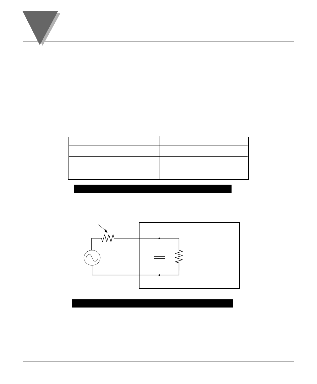
3
A
BOUTTRUE
RMS M
EASUREMENT
3.3 Voltage-Divider Action of Leads and Meter Input Impedance
The meter’s voltage input impedance is nearly one meg ohm in parallel
with 10pF of capacitance, drawing negligible current from most voltage
sources.
Significant impedance from high-frequency sources should be taken into
account when the greatest possible accuracy is needed. Also, consider
the capacity from lead to lead and leakage resistance, if significant.
Table 3.1 below gives the net loading impedance of the meter at
different frequencies.
Table 3.1 — Meter Net Loading Impedance
Figure 3.2 — Approximate Input Resistance
INPUT FREQUENCY INPUT IMPEDANCE
100 Hz 1 MΩ
1 kHz 940 kΩ
10 kHz 614 kΩ
50
Source Resistance
Meter
Page 59

51
A
BOUTTRUE
RMS M
EASUREMENT
3.4 Input Current Effects
The meter’s input amplifier has a DC bias current less than 350pA for
an ambient temperature less than 30°C (86°F). This current doubles
about every 8°C above this point. This small current can produce small
DC offset voltages in the impedance of the source. These offsets are
readily measured by the meter when the AC stimulus is removed or a
dummy source impedance is connected across the input terminals. The
resulting offsets can be added or subtracted from the DC source value
to increase the data accuracy.
Any AC pickup voltages measured in the above condition must
not be added or subtracted linearly from the AC source value.
They must be RMS-combined.
3.5 Overvoltage Heating
If you apply more than the rated voltage on any range it will increase
the heating in the meter’s signal conditioner. The effects of momentary
overvoltage will not add more than 0.02%. This overvoltage error will
dissipate in a few minutes after removal of the overvoltage.
3.6 Guarding Against AC Pickup
The meter has a high input impedance to accurately measure sources
which have high source impedance of up to 100kΩ. This means that the
meter can respond to extraneous sources of AC voltage or current if
they have significant capacitance or mutual inductance to the input
leads.
For example, the space surrounding florescent lighting usually has a
strong alternating electrostatic field (volts per meter). This field will push
andor pull charge in any nearby exposed conductor. Within its vicinity,
use shielded cable for input leads to drain away any capacitive current
to ground. (Tie the shield to the input RTN terminal.) This is particularly
important when measuring small signals at line frequency. Be especially
careful to shunt away any pickup currents.
3
Note
☞
Page 60

3
A
BOUTTRUE
RMS M
EASUREMENT
If the signal leads must pass by equipment with large AC currents, use
twisted-pair cable to minimize induced currents. You may also use
magnetic shielding materials to reduce these effects, but the best
solution is to reroute the signal wires away from such currents.
Ground-loop currents are another possible source of error. If the AC
signal source has resistive or capacitive coupling to an AC power
source, and that source is not supplying the meter, current can flow in
the loop formed by the source, meter and power circuits, causing a
reading error.
Whenever possible, drive the meter and the signal source from the
same power outlet. When different outlets must be used, both should be
from the same AC line-power phase. A convenient way to check for
outlet voltage differences is with a hand-held multimeter.
3.7 Common-Mode Voltage Effects
Although DC-isolated, the meter’s RTN terminal has approximately
100pF of capacity to power-supply ground. If the signal source return
has an AC voltage with respect to that ground, some current will flow in
that lead, and possibly degrade the data. In this situation, reverse the
connections of the source to the INPUT and RTN leads, then observe
any differences in meter output. These differences in meter output may
show which polarity offers superior performance.
52
Page 61

53
D
EFAULTS ANDSPECIFICATIONS
4
Section 4: Defaults and
Specifications
Back of the Meter
Main Board
W1–W3 Solder Jumpers
Signal Board
Meter Housing
Factory Default Values
Meter Specifications
Glossary
Page 62
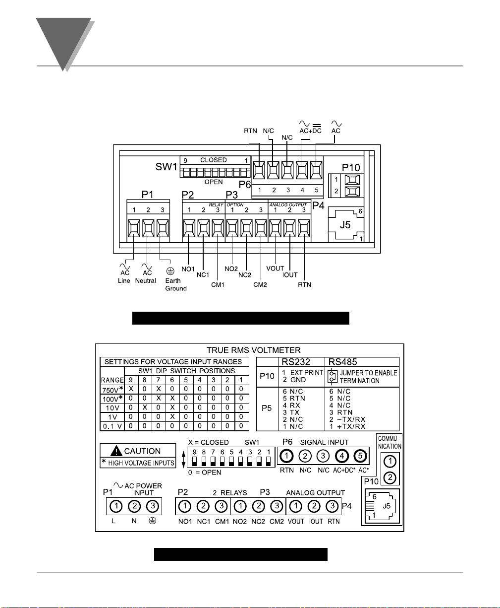
4
D
EFAULTS ANDSPECIFICATIONS
4.1 Back of the Meter
Figure 4.1 — Volt Meter Connections
Figure 4.2 – Volt Meter Label
54
Page 63
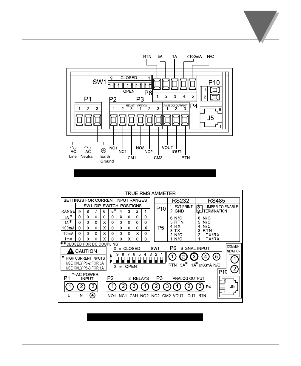
55
D
EFAULTS ANDSPECIFICATIONS
Figure 4.3 — Current Meter Connections
Figure 4.4 – Current Meter Label
4
Page 64

4
D
EFAULTS ANDSPECIFICATIONS
4.2 Main Board
Figure 4.5 — Jumper Positions on the Main Board
Table 4.1 — Jumper Functions
Jumper Function
J7 Used for the optional serial communications card. The default is not
installed.
S1 Install where load impedance of analog output voltage is <1KΩ.
S2A Install to prevent access to menu items. If S2A is installed you may change
setpoints only and view peak and valley. The default is not installed.
S2B Install to enable access to all front panel push-buttons. Remove to disable
access to all front-panel push-buttons. The default is installed.
S2C Install S2C for calibration and make sure that S2A is removed if you want to
calibrate the meter. The default is not installed.
56
Page 65
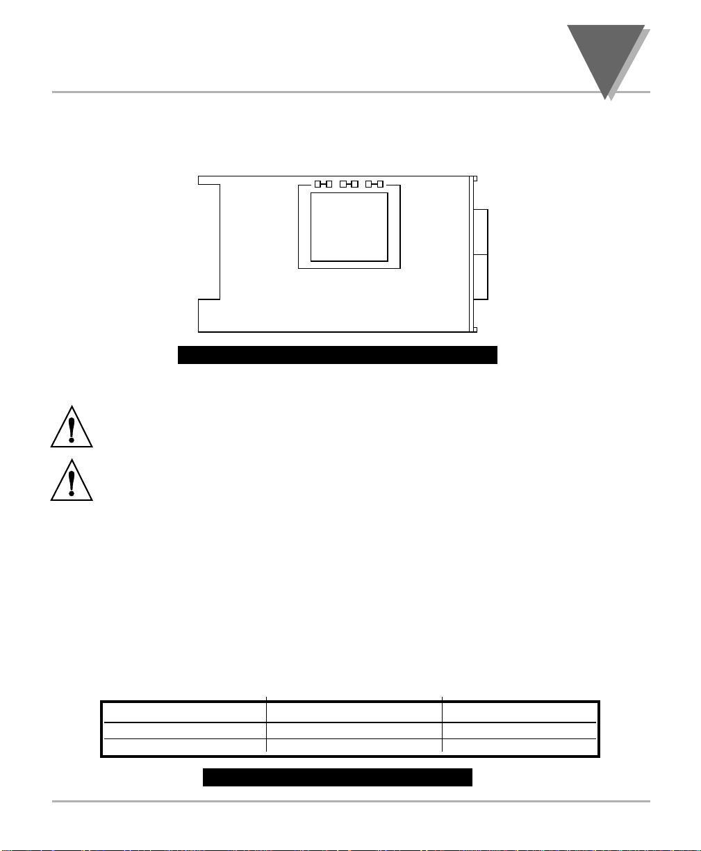
57
D
EFAULTS ANDSPECIFICATIONS
4.3 W1–W3 Solder Jumpers
Figure 4.6 — W1–W3 Jumper Locations
Figure 4.6 shows the location of solder jumpers W1 through W3.
CAUTION: The meter has no power-on switch, so it will be in operation as soon as you
apply power.
IMPORTANT: These changes must be performed by a qualified technician. If you want to
change the Factory preset jumpers, do the following steps; otherwise go to Section 4.5.
Disconnect the power from the unit before proceeding.
1. Remove the main board from the case. (See Figure 4.8)
2. Locate the solder jumpers W1, W2, and W3 (located near the edge of the main
board alongside the transformer).
3. If your power requirement is 115 V ac, wire jumpers W1 and W3 should be
wired, but jumper W2 should not.
If your power requirement is 230 V ac, wire jumper W2 should be wired, but jumpers
W1 and W3 should be open. (See Table 4.2)
Table 4.2 W1-W3 Jumper wiring
AC VOLTAGE INSTALL REMOVE
115VAC W1, W3 W2
230VAC W2 W1, W3
4
W2W1 W3
T1
MAIN BOARD
DISPLAY BOARD
Page 66
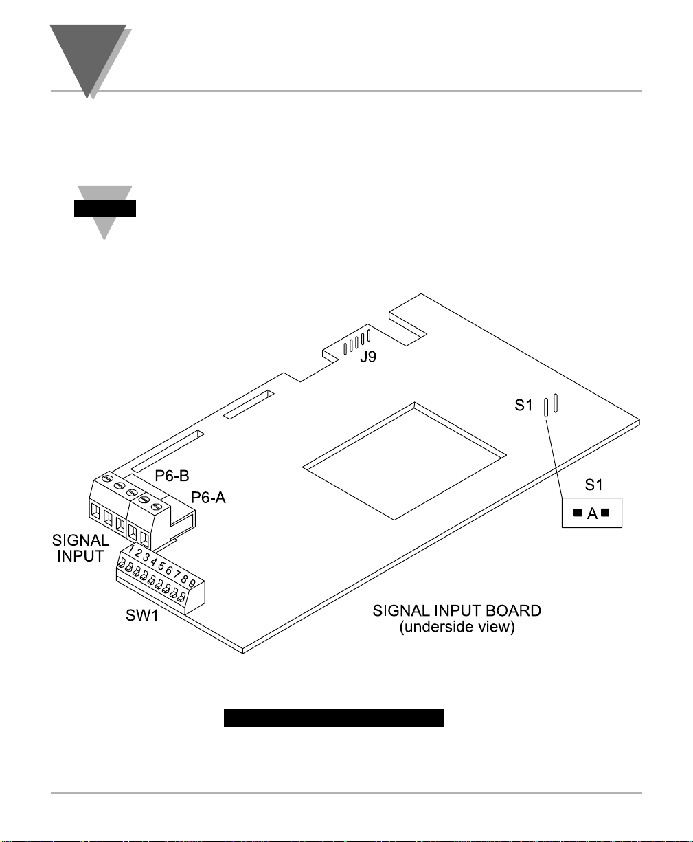
4
D
EFAULTS ANDSPECIFICATIONS
58
4.4 Signal Board
The signal board fits on top of the main board and must be properly
secured to the main board for the meter to function. See Figure 4.8.
For faster response time, remove the S1 jumper. The default is jumper
installed.
Figure 4.7 — Signal Board
Note
5
☞
4
3
2
1
Page 67
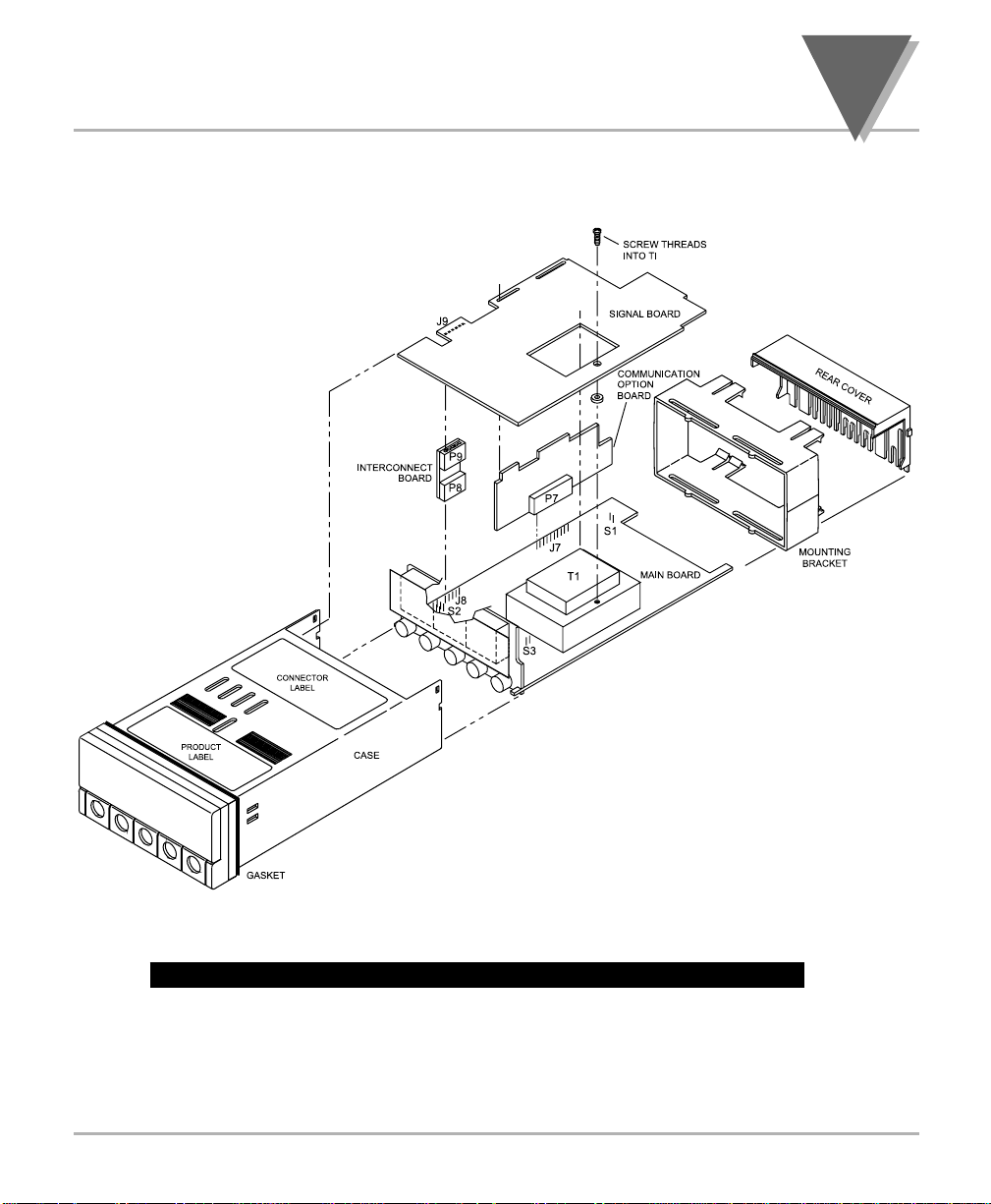
59
D
EFAULTS ANDSPECIFICATIONS
4
Figure 4.8 — Exploded View of Case and Board Assembly
Page 68
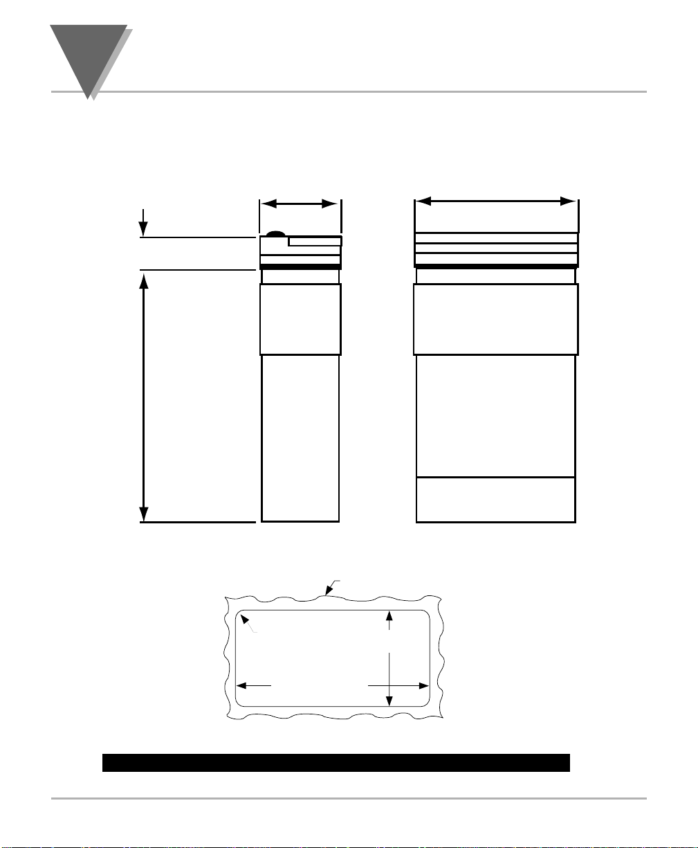
4
D
EFAULTS ANDSPECIFICATIONS
4.5 Meter Housing
Figure 4.9 — Meter Housing and Panel Cut-out Dimensions
60
20,3 (.80)
151,4 (5.96)
96,0 (3.78)48,0 (1.89)
FRONT BEZEL
RETAINER
CASE
REAR COVER
SIDE VIEW
PANEL THICKNESS
6,4 (.25) MAX
0,8 (.03) MIN
1,5
R
(.06)
4 PLCS
92,00 + 0,81/–0,00
(3.622 + .032/–.000)
NOTE: Dimensions in Millimeters (Inches)
45,00 + 0,61/-0,00
(1.772 + .024/–.000)
TOP VIEW
Page 69

61
D
EFAULTS ANDSPECIFICATIONS
4.6 Factory Default Values
4.6.1 Menu Item Defaults
Menu Item Description Volt Current
RNGE Input Type 750 V** 5A
FREQ Frequency 60 HZ
*
60 HZ
*
50 HZ
†
50 HZ
†
CPLG Coupling Type ~AC ==DC
DEC.P Decimal Point FFF.F F.FFF
FLTR Filter Value 64 64
UNIT Volt / Amp V A
Table 4.3 — Menu Item Defaults
4.6.2 Analog Output Scale and Offset Defaults
Menu Item Description Volt Current
RD 1 Reading 1 000.0 0.000
OUT1 Output 1 4.00 (mA) 04.00 (mA)
RD 2 Reading 2 750.0 5.000
OUT2 Output 2 20.00 (mA) 20.00 (mA)
Table 4.4 — Analog Output Scale and Offset Defaults
* — if powered by 115V, 60 Hz power source
** -- for CE compliance, the max range is 300V, see CE Approvals Section for full details.
†
— if powered by 230V, 50 Hz power source
4
Page 70

4
D
EFAULTS ANDSPECIFICATIONS
4.7 Meter Specifications
4.7.1 Signal Input
Input Ranges: Voltage Model: 100mV, 1V, 10V, 100V, 750V*
Current Model: 1mA, 10mA, 100mA, 1A, 5A
Input Impedance for Volt Meter:
For all voltage ranges 1.0MegΩ ± 1%
Input Impedance for Current Meter:
For 5 AMP 0.05Ω ± 5%
For 1 AMP 0.15Ω ± 2%
For 100 mA 1.15Ω ± 1%
For 10 mA 11.1Ω ± 1%
For 1 mA 111.1Ω ± 1%
Table 4.5 — Signal Input Specifications
4.7.2 Display
4-digit
Red or Green
LED 14-segment
13.8mm (0.54”)
Symbols: 8.8.8.8.
Table 4.6 — Display Specifications
62
Page 71

63
D
EFAULTS ANDSPECIFICATIONS
4.7.3 Tempco for Volt Meter
100 mV Range Typical 0.015% / °C
1,10,100, 750V Range Typical 0.01% / °C
Table 4.7 — Span Tempco for Voltmeter
4.7.4 Tempco for Current Meter
1, 10, 100 mA Range Typical 0.015% / °C 400 PPM/°C
1 AMP Typical 0.02% / °C 600 PPM/°C
5 AMP Typical 0.025% / °C 800 PPM/°C
Table 4.8 — Span Tempco for Current Meter
4.7.5 Analog to Digital
Technique Dual Slope
Internal Resolution 15 bits
Read Rate 2.5 Readings per second
Crest Factor 4
Warm Up Time to Rated Accuracy 30 minutes
Table 4.9 — Analog to Digital Specifications
4
Page 72

4
D
EFAULTS ANDSPECIFICATIONS
4.7.6 Isolated Analog Output (If Applicable)
Signal Type Current or Voltage
Signal Level Current: 10 V max compliance at 20 mA output
Voltage: 20 mA max for 0–10 V output
Function Assigned to a display range
Linearity 0.2%
Step Response Time 2–3 seconds to 99% of the final value
Table 4.10 — Isolated Analog Output Specifications
4.7.7 Communications Information (If Applicable)
RS-232: RJ12 6-wire connection; complete program setup and message display
capability; programmable to transmit current display, alarm status, and
peak/valley status.
Baud Rates: 300, 600, 1200, 2400, 4800, 9600, 19200
RS-485: RJ12 6-wire connection; addressable from “000” to “199”
Baud Rates: 300, 1200, 2400, 4800, 9600, 19200
Table 4.11 — Communications Information
4.7.8 Input Power Information
ac Voltage 115/230 Vrms 10%
Frequency 50/60 Hz
Power 7 watts max.
Table 4.12 — Input Power Specifications
64
Page 73

65
D
EFAULTS ANDSPECIFICATIONS
4.7.9 Operating Environment
Operating Temperature: °0 to 60°C (32 °F to 140 °F)
(115/230 Vrms 10%)
°0 to 40°C (32 °F to 104 °F)
(115/230 Vrms 15%) When Relay Output Option is used.
Storage Temperature: -40°C to 85°C
(-40°F to 185°F)
Relative Humidity: 90% at 40°C
(non-condensing)
Table 4.13 — Operating Environment
4.7.10 Mechanical
Panel Cutout: 1/8 DIN 3.62" x 1.78"
(45 x 92mm)
Weight: 1.27 lb (575 g)
Case Material Polycarbonate, 94 V-O
UL rated
Table 4.14 — Mechanical Specifications
4.7.11 Alarm Outputs (If Applicable)
2 Form C on/off relays
Latched and unlatched status configurable by software
Maximum current: 5 AMPS
Maximum Voltage: 250 Vac or 30 Vdc
Table 4.15 — Alarm Outputs
4
Page 74

4
D
EFAULTS ANDSPECIFICATIONS
4.7.12 Voltage Model Accuracy ( ≠ DC coupled inputs)
Frequency Accuracy
At 50, 60 Hz 0.1%R ±10 counts
At ≠DC 0.1%R ±15 counts
from 50Hz To 1 KHz 0.1%R ±20 counts
from 40Hz To 3 KHz 0.1%R ±30 counts
from 25Hz To 5 KHz (except 100mV) 0.1%R ±40 counts
from 25Hz To 4 KHz (100mV only) 0.1%R ±50 counts
The specifications are valid from 5% to 100% of each range.
Table 4.16 — Voltage Model Accuracy (≠DC coupled inputs)
4.7.13 Voltage Model ( ~AC coupled inputs)
Frequency Accuracy
at 50, 60 Hz 0.1%R ±10 counts
from 50Hz to 1 KHz 0.1%R ±30 counts
from 40Hz to 3 KHz 0.1%R ±40 counts
from 25Hz to 5 KHz (except 100mV) 0.1%R ±50 counts
from 25Hz to 4 KHz (100mV only) 0.1%R ±60 counts
The specifications are valid from 5% to 100% of each range.
Table 4.17 — Voltage Model Accuracy (~AC coupled inputs)
66
Page 75

67
D
EFAULTS ANDSPECIFICATIONS
4
4.7.14 Current Model ( ~AC or ≠DC coupled inputs)
Frequency Accuracy
at 50, 60 Hz 0.1%R ±10 counts
at ≠DC 0.1%R ±15 counts
from 50Hz to 1 KHz 0.1%R ±20 counts
from 40Hz to 3 KHz 0.1%R ±30 counts
from 25Hz to 5 KHz (except 5 AMP) 0.1%R ±40 counts
from 25Hz to 4 KHz (5 AMP only) 0.1%R ±50 counts
The specifications are valid from 5% to 100% of each range.
Table 4.18 — Current Model Accuracy
4.7.15 Decimal Point & Unit of Measure Defaults
Range Decimal Point Unit of Measure
Volt Meter: 100mV 99.99 mV
1V 999.9 mV
10V 9.999 V
100V 99.99 V
750V* 750.0 V
* see CE Approvals section for full details.
Range Decimal Point Unit of Measure
Current Meter: 1mA 999.9 no unit
10mA 9.999 mA
100mA 99.99 mA
1A 999.9 mA
5A 5.000 A
Note that at any time you can change the decimal point position and or the unit of measure to
any position or value you want.
Table 4.19 — Decimal Point & Unit of Measure Defaults
Page 76
4
D
EFAULTS ANDSPECIFICATIONS
4.7.16 Insulation
Power to Input/Output 2500 Vrms per 1 min. test
Power to Relay Outputs
2500 Vrms per 1 min. test
Relays to Inputs/Outputs 2500 Vrms per 1 min. test
RS-232/RS-485 to Inputs/Outputs
500 Vrms (720 Vdc) per 1 min. test
Analog Output to Inputs
500 Vrms (720 Vdc) per 1 min. test
Table 4.20 — Insulation Table
68
Page 77

69
D
EFAULTS ANDSPECIFICATIONS
4.8 Glossary
The substanitive portion of this glossary lists and defines all of the display messages and error
display messages that may appear on your meter. Please keep this information with the
Operator's Manual at all times.
Message Description
232C RS232C Standard
485 RS485 Standard
ABOV Setpoint Active Above
ADDR RS485 Device Address
ALL All Input Signal Frequencies
other than 50Hz & 60Hz
BAUD Baud Rate
BELO Setpoint Active Below
BUS.F Communication Bus Format
C.SUM Checksum
CMD Transmission on Command
COM.P Communication Parameters
COMM Communication Top Menu
CONT Continuous Transmission
CPLG Input Coupling
CR Carriage Return
CURR Analog Output Current Mode
DAT.F Communication Data Format
DATA Data Bits
Message Description
DATE Date
DEC.P Decimal Point Position
DFLT Analog Output Default Mode
ECHO Echo Response
FLTR Filter Value
FREQ Input Signal Frequency
ID Measurement Value ID
INPT Input Top Menu
LF Linefeed
LTCH Setpoint Latch
M.BUS ModBus Protocol
MODE Mode of Communication
NEW.P Protocol
NORM Setpoint Nonlatch
OT.CF Analog Output Configuration
OT.S.O Analog Output 2 Point
Calibration
OUT Output Configuration Top
Menu
PEAK Peak Value
4
Page 78

4
D
EFAULTS ANDSPECIFICATIONS
Please note that all of the following error messages flash while displayed.
Error
Message Description
+OL Input Signal Overload
-OL Input Signal Underload
9999 Reading is Overflowed
ER1 2-Coordinate Programming
Error
Error
Message Description
RD.OF The reading output is larger
than 11000 due to scaling.
(value) If the displayed value is
flashing, then the reading is
overrange (between 10000
to 11000)
Message Description
PK.RS Reset Peak Value
PROG Analog Output
Programming Mode
PROT Communication Protocol
PRTY Parity Bit
RD.S.O Reading Scale and Offset (2
point Calibration)
RDNG Reading Configuration Top
Menu
RNGE Input Signal Range
S1.DB Setpoint 1 Deadband
S2.DB Setpoint 2 Deadband
SEPR Data Separator
SP.CF Setpoint Configuration Top
Menu
SPCE Space
Message Description
SPT.1 Setpoint 1 Deadband and
Alarm
SPT.2 Setpoint 2 Deadband and
Alarm
STAT Status Character
STND Communication Standard
STOP Stop Bits
STRD Stored
TIME Time Value
TX.TI Time Between Transmission
UNIT Unit of Measurement
VALY Valley Value
VL.RS Reset Valley Value
VOLT Analog Output Volt Mode
70
Page 79
71
CE A
PPROVALSINFORMATION
5
This product conforms to the EMC directive 89/336/EEC amended by 93/68/EEC,
and with the European Low Voltage Directive 72/23/EEC.
Electrical Safety EN61010-1:2001
Safety requirements for electrical equipment for measurement, control and laboratory.
Current Ranges: 1mA, 10mA, 100mA, 1A, and 5A.
Voltage Ranges: 0.1V, 1V, 10V, 100V, and 750V*.
*For the 750V range, see the following page of Special Safety Ratings.
Double Insulation
Pollution Degree 2
Dielectric withstand Test per 1 min (50/60 Hz)
• Power to Input/Output: 2500Vrms
• Power to Relay Output: 2500Vrms
• Relay Output to Inputs/Outputs: 2500Vrms
• Isolated RS232/485 to Inputs: 500Vrms (720Vdc)
• Analog Output to Inputs: 500Vrms (720Vdc)
Measurement Category II
Category II are measurements performed on circuits directly connected to the Mains Supply
(power). Maximum Line-to-Neutral working voltage is 100 Vac/dc.
This unit should not be used in Measurement Categories III and IV, but Catagory I
(measurements performed on circuits not directly connected to the Mains Supply) is
allowed.
For current and voltage connections, the Installation Requirements of this manual must be
followed.
Transients Overvoltage Surge (1.2 / 50uS pulse)
• Input Power: 2500V
• Output Relays: 2500V
• Input/Output Signals: 500V
EMC EN61326:1997 + and A1:1998 + A2:2001
Immunity and Emissions requirements for electrical equipment for measurement, control and
laboratory.
• EMC Emissions Class B of EN61326
• EMC Immunity** Table 1 of EN61326
Note: **I/O signal and control lines require shielded cables and these cables must be
located on conductive cable trays or in conduits. Furthermore, the length of these
cables should not exceed 30 meters
Refer to the EMC and Safety installation considerations (Guidelines) of this manual for
additional information.
Page 80
5
CE A
PPROVALSINFORMATION
72
This product conforms to the EMC directive 89/336/EEC amended by 93/68/EEC,
and with the European Low Voltage Directive 72/23/EEC.
Electrical Safety EN61010-1:2001
Safety requirements for electrical equipment for measurement, control and laboratory.
Voltage Range of 750V The 750V is de-rated to 300V max. range to meet Double
Insulation requirements for CE. No Analog or Serial Communication should be used when
operating this de-rated range of 300V.
Input Range 300V max. 50/60Hz (on 750V range)
Double Insulation
Pollution Degree 2
Dielectric withstand Test per 1 min (50/60 Hz)
• Power to Input: 2500Vrms
• Power to Relay Output: 2500Vrms
• Relay Output to Inputs: 2500Vrms
• Isolated RS232/485 to Inputs: not used
• Analog Output to Inputs: not used
Measurement Category II
Category II are measurements performed on circuits directly connected to the Mains Supply
(power). Maximum Line-to-Neutral working voltage is 300 Vac/dc.
This unit should not
be used in Measurement Categories III and IV.
For current and voltage connections, the Installation Requirements of this manual must be
followed.
The CE compliance described above are null when Analog or Serial options are used
or the Input Voltage is beyond the de-rated 300V max scale range.
This unit will work 300 - 750 V but the isolation is only Basic, provided that the relays
are not used to activate DC loads requiring Double Insulation to any hazardous
voltages (Mains).
Transients Overvoltage Surge (1.2 / 50uS pulse)
• Input Power: 2500V
• Output Relays: 2500V
• Input Signals: 2500V
EMC EN61326:1997 + and A1:1998 + A2:2001
Immunity and Emissions requirements for electrical equipment for measurement, control and
laboratory.
• EMC Emissions Class B of EN61326
• EMC Immunity** Table 1 of EN61326
Note: **I/O signal and control lines require shielded cables and these cables must be
located on conductive cable trays or in conduits. Furthermore, the length of these
cables should not exceed 30 meters
Refer to the EMC and Safety installation considerations (Guidelines) of this manual for
additional information.
Page 81

WARRANTY/DISCLAIMER
OMEGA ENGINEERING, INC. warrants this unit to be free of defects in materials and workmanship for a period of
one (1) year from the date of purchase. In addition to OMEGA’s standard warranty period, OMEGA Engineering will
extend the warranty period for four (4) additional years if the warranty card enclosed with each instrument is
returned to OMEGA.
If the unit malfunctions, it must be returned to the factory for evaluation. OMEGA’s Customer Service Department
will issue an Authorized Return (AR) number immediately upon phone or written request. Upon examination by
OMEGA, if the unit is found to be defective, it will be repaired or replaced at no charge. OMEGA’s WARRANTY does
not apply to defects resulting from any action of the purchaser, including but not limited to mishandling, improper
interfacing, operation outside of design limits, improper repair, or unauthorized modification. This WARRANTY is
VOID if the unit shows evidence of having been tampered with or shows evidence of having been damaged as a
result of excessive corrosion; or current, heat, moisture or vibration; improper specification; misapplication; misuse
or other operating conditions outside of OMEGA’s control. Components which wear are not warranted, including but
not limited to contact points, fuses, and triacs.
OMEGA is pleased to offer suggestions on the use of its various products. However, OMEGA neither
assumes responsibility for any omissions or errors nor assumes liability for any damages that result from
the use of its products in accordance with information provided by OMEGA, either verbal or written.
OMEGA warrants only that the parts manufactured by it will be as specified and free of defects. OMEGA
MAKES NO OTHER WARRANTIES OR REPRESENTATIONS OF ANY KIND WHATSOEVER, EXPRESS OR
IMPLIED, EXCEPT THAT OF TITLE, AND ALL IMPLIED WARRANTIES INCLUDING ANY WARRANTY OF
MERCHANTABILITY AND FITNESS FOR A PARTICULAR PURPOSE ARE HEREBY DISCLAIMED. LIMITATION
OF LIABILITY: The remedies of purchaser set forth herein are exclusive, and the total liability of OMEGA
with respect to this order, whether based on contract, warranty, negligence, indemnification, strict liability
or otherwise, shall not exceed the purchase price of the component upon which liability is based. In no
event shall OMEGA be liable for consequential, incidental or special damages.
CONDITIONS: Equipment sold by OMEGA is not intended to be used, nor shall it be used: (1) as a “Basic
Component” under 10 CFR 21 (NRC), used in or with any nuclear installation or activity; or (2) in medical
applications or used on humans. Should any Product(s) be used in or with any nuclear installation or activity,
medical application, used on humans, or misused in any way, OMEGA assumes no responsibility as set forth
in our basic WARRANTY/DISCLAIMER language, and, additionally, purchaser will indemnify OMEGA and hold
OMEGA harmless from any liability or damage whatsoever arising out of the use of the Product(s) in such a
manner.
RETURN REQUESTS/INQUIRIES
Direct all warranty and repair requests/inquiries to the OMEGA Customer Service Department. BEFORE
RETURNING ANY PRODUCT(S) TO OMEGA, PURCHASER MUST OBTAIN AN AUTHORIZED RETURN
(AR) NUMBER FROM OMEGA’S CUSTOMER SERVICE DEPARTMENT (IN ORDER TO AVOID
PROCESSING DELAYS). The assigned AR number should then be marked on the outside of the return
package and on any correspondence.
The purchaser is responsible for shipping charges, freight, insurance and proper packaging to prevent
breakage in transit.
FOR WARRANTY RETURNS, please have the
following information available BEFORE
contacting OMEGA:
1. Purchase Order number under which the product
was PURCHASED,
2. Model and serial number of the product under
warranty, and
3. Repair instructions and/or specific problems
relative to the product.
FOR NON-WARRANTY REPAIRS,
consult OMEGA for
current repair charges. Have the following information
available BEFORE contacting OMEGA:
1. Purchase Order number to cover the COST
of the repair,
2. Model and serial number of product, and
3. Repair instructions and/or specific problems
relative to the product.
OMEGA’s policy is to make running changes, not model changes, whenever an improvement is possible. This affords our customers
the latest in technology and engineering.
© Copyright 2006 OMEGA ENGINEERING, INC. All rights reserved. This document may not be copied, photocopied, reproduced,
translated, or reduced to any electronic medium or machine-readable form, in whole or in part, without the prior written consent of
OMEGA ENGINEERING, INC.
TRADEMARK NOTICE:
®
,
omega.com
®
and are trademarks of OMEGA Engineering, Inc.
PATENT NOTICE:
This product is covered by one or more of the following patents: U.S. Pat. No. Des. 336,895; 5,274,577;
6,243,021 / CANADA 2052599; 2052600 / ITALY 1249456; 1250938 / FRANCE BREVET No. 91 12756 / SPAIN 2039150; 2048066 /
UK PATENT No. GB2 249 837; GB2 248 954 / GERMANY DE 41 34398 C2.
The “Meter Case Bezel Design” is a trademark of
NEWPORT Electronics, Inc., registered in the U.S.
USED UNDER LICENSE. Other US and International Patents pending or
applied for.
®
Page 82

M2295/1106 11969ML-98 Rev D
Where Do I Find Everything I Need for
Process Measurement and Control?
OMEGA…Of Course!
Shop on line at omega.com
TEMPERATURE
Thermocouple, RTD & Thermistor Probes, Connectors, Panels & Assemblies
Wire: Thermocouple, RTD & Thermistor
Calibrators & Ice Point References
Recorders, Controllers & Process Monitors
Infrared Pyrometers
PRESSURE, STRAIN AND FORCE
Transducers & Strain Gauges
Load Cells & Pressure Gauges
Displacement Transducers
Instrumentation & Accessories
FLOW/LEVEL
Rotameters, Gas Mass Flowmeters & Flow Computers
Air Velocity Indicators
Turbine/Paddlewheel Systems
Totalizers & Batch Controllers
pH/CONDUCTIVITY
pH Electrodes, Testers & Accessories
Benchtop/Laboratory Meters
Controllers, Calibrators, Simulators & Pumps
Industrial pH & Conductivity Equipment
DATA ACQUISITION
Data Acquisition & Engineering Software
Communications-Based Acquisition Systems
Plug-in Cards for Apple, IBM & Compatibles
Datalogging Systems
Recorders, Printers & Plotters
HEATERS
Heating Cable
Cartridge & Strip Heaters
Immersion & Band Heaters
Flexible Heaters
Laboratory Heaters
ENVIRONMENTAL
MONITORING AND CONTROL
Metering & Control Instrumentation
Refractometers
Pumps & Tubing
Air, Soil & Water Monitors
Industrial Water & Wastewater Treatment
pH, Conductivity & Dissolved Oxygen Instruments
 Loading...