

Page 1
TM
User’s Guide
Shop online at
omega.com
e-mail: [email protected]
For latest product manuals:
www.omegamanual.info
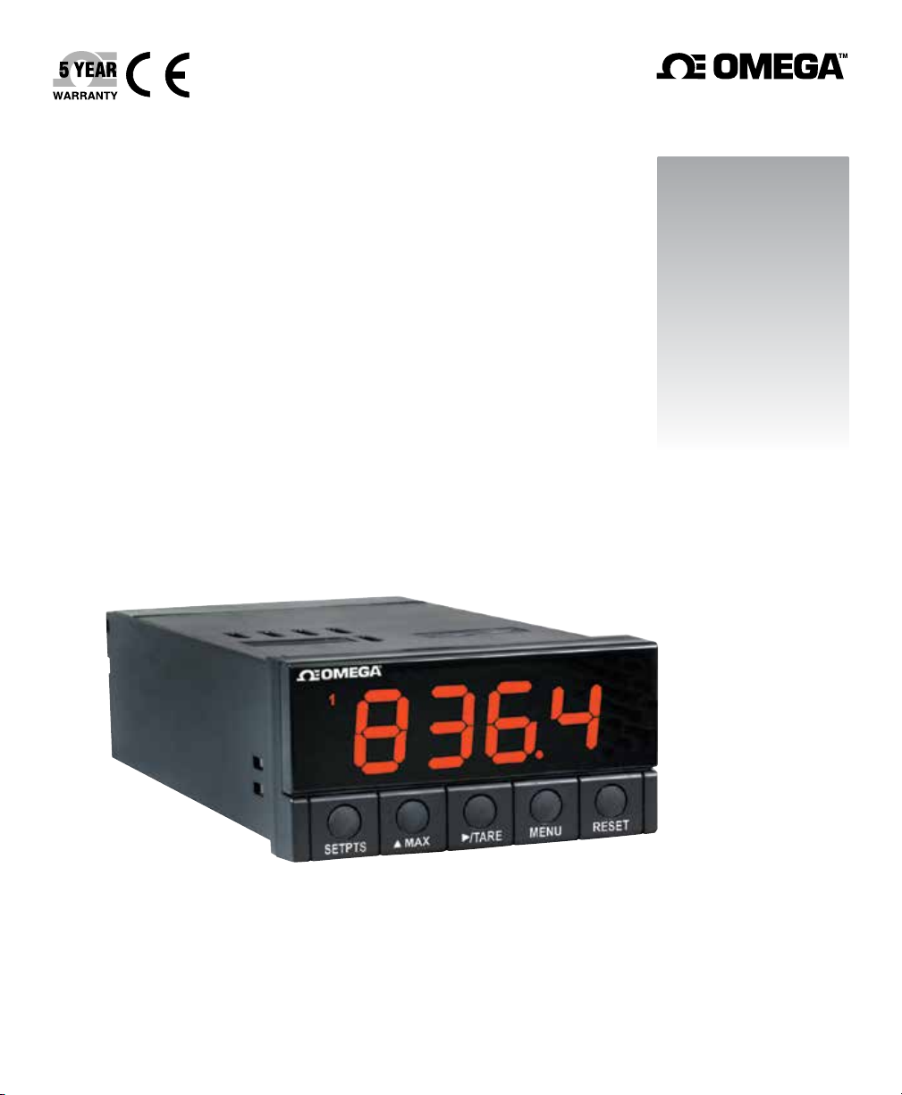
DP25B-E
Process Panel Meter
Page 2

omega.com [email protected]
Servicing North America:
U.S.A. Omega Engineering, Inc.
Headquarters: Toll-Free: 1-800-826-6342 (USA & Canada only)
Customer Service: 1-800-622-2378 (USA & Canada only)
Engineering Service: 1-800-872-9436 (USA & Canada only)
Tel: (203) 359-1660 Fax: (203) 359-7700
e-mail: [email protected]
For Other Locations Visit omega.com/worldwide
The information contained in this document is believed to be correct, but OMEGA accepts no liability for any errors it
contains, and reserves the right to alter specifications without notice.
Page 3

i
Table of Contents
PREFACE
Manual Objectives
This manual shows you how to set up and use the Programmable Digital Meter.
Standard Procedures:
* Checking voltage jumpers, or changing voltage power
* Mounting the panel
* Selecting the input type
* Selecting a decimal point position
* Scaling with known loads (on-line calibration)
* Scaling without known loads
* Enabling/disabling the front-panel tare
* Displaying the filtered/unfiltered input signal
* Selecting a display color
* Setting the setpoint's active band
* Selecting a latched or unlatched operation
* Setting setpoint deadbands
* Enabling/disabling setpoint changes
* Enabling/disabling the RESET button in the Run Mode
Optional Procedures:
* Setting input resolution
* Enabling/disabling analog output
* Selecting analog output as current or voltage
* Selecting analog output or proportional control
* Selecting proportional band
* Using manual reset (offsetting setpoint errors)
* Scaling analog output
For first-time users: Refer to the QuickStart Manual for basic operation and setup instructions.
Page 4
Table of Contents
ii
Table A-1. Sections of the Manual
If you want to read about:
Unpacking; safety considerations
Meter description and features
Main board power jumpers; panel
mounting, sensor input, main power and
analog and relay output
Input type; decimal point position;
reading scale & offset; reading
configuration; display color; setpoint
configuration; setpoint deadbands;
output configuration (analog output);
proportional band; manual reset; analog
output scaling; lock out configuration;
display brightness
Display messages
Meter menu/sub-menu messages
Setpoint configuration messages
Specifications
Factory Preset Values
1
2
3
4
5
6
7
8
9
Refer to section
Introduction
About the Meter
Getting Started
Configuring the Meter
Display Messages
Menu Configuration
Setpoint Configuration
Displays
Specifications
Factory Default
Setup as Shipped
Page 5

iii
Table of Contents
Table of Contents
Section Page
SEC 1 INTRODUCTION . . . . . . . . . . . . . . . . . . . . . . . . . . . . . . . . . . . . . . . . . . . .1
1.1 Unpacking . . . . . . . . . . . . . . . . . . . . . . . . . . . . . . . . . . . . . . . . . . . . . . . . .1
1.2 Safety Considerations . . . . . . . . . . . . . . . . . . . . . . . . . . . . . . . . . . . . . . . .2
SEC 2 ABOUT THE METER . . . . . . . . . . . . . . . . . . . . . . . . . . . . . . . . . . . . . . . .3
2.1 Description . . . . . . . . . . . . . . . . . . . . . . . . . . . . . . . . . . . . . . . . . . . . . . . . .3
2.2 Features . . . . . . . . . . . . . . . . . . . . . . . . . . . . . . . . . . . . . . . . . . . . . . . . . . .3
2.3 Available Accessories . . . . . . . . . . . . . . . . . . . . . . . . . . . . . . . . . . . . . . . .4
2.4 Front of the Meter . . . . . . . . . . . . . . . . . . . . . . . . . . . . . . . . . . . . . . . . . . .5
2.5 Back of the Meter . . . . . . . . . . . . . . . . . . . . . . . . . . . . . . . . . . . . . . . . . . . .8
2.6 Disassembly . . . . . . . . . . . . . . . . . . . . . . . . . . . . . . . . . . . . . . . . . . . . . .10
SEC 3 GETTING STARTED . . . . . . . . . . . . . . . . . . . . . . . . . . . . . . . . . . . . . . . .11
3.1 Rating/Product Label . . . . . . . . . . . . . . . . . . . . . . . . . . . . . . . . . . . . . . . .11
3.2 Main Board Power Jumpers . . . . . . . . . . . . . . . . . . . . . . . . . . . . . . . . . . .11
3.3 Panel Mounting . . . . . . . . . . . . . . . . . . . . . . . . . . . . . . . . . . . . . . . . . . . .14
3.4 Connecting Sensor Inputs . . . . . . . . . . . . . . . . . . . . . . . . . . . . . . . . . . . .15
3.5 Connecting Main Power . . . . . . . . . . . . . . . . . . . . . . . . . . . . . . . . . . . . . .18
3.6 Conecting External Tare Switch . . . . . . . . . . . . . . . . . . . . . . . . . . . . . . . .20
3.7 Connecting Analog and Relay Outputs . . . . . . . . . . . . . . . . . . . . . . . . . .20
SEC 4 CONFIGURING THE METER . . . . . . . . . . . . . . . . . . . . . . . . . . . . . . . . .22
4.1 Selecting the Input Type . . . . . . . . . . . . . . . . . . . . . . . . . . . . . . . . . . . . .22
4.2 Selecting a Decimal Point Position . . . . . . . . . . . . . . . . . . . . . . . . . . . . .23
4.3 Selecting Reading Scale and Offset . . . . . . . . . . . . . . . . . . . . . . . . . . . .23
4.3.1 Scaling with Known Loads . . . . . . . . . . . . . . . . . . . . . . . . . . . . . . . . . . . .24
4.3.2 Scaling without Known Loads . . . . . . . . . . . . . . . . . . . . . . . . . . . . . . . . .27
4.4 Using Reading Configuration . . . . . . . . . . . . . . . . . . . . . . . . . . . . . . . . . .28
4.4.1 Enabling or Disabling the Front-Panel Tare . . . . . . . . . . . . . . . . . . . . . . .29
4.4.2 Setting Input Resolution . . . . . . . . . . . . . . . . . . . . . . . . . . . . . . . . . . . . . .29
4.4.3 Displaying the Filtered/Unfiltered Input Signal . . . . . . . . . . . . . . . . . . . . .30
Page 6

Table of Contents
iv
Table of Contents
Section Page
4.5 Selecting a Display Color . . . . . . . . . . . . . . . . . . . . . . . . . . . . . . . . . . . . .30
4.6 Using Setpoint 1 Configuration . . . . . . . . . . . . . . . . . . . . . . . . . . . . . . . .31
4.6.1 Setting Setpoint 1's Active Band . . . . . . . . . . . . . . . . . . . . . . . . . . . . . . .31
4.6.2 Selecting if Setpoint 1 is Latched or Unlatched . . . . . . . . . . . . . . . . . . . .31
4.7 Using Setpoint 2 Configuration . . . . . . . . . . . . . . . . . . . . . . . . . . . . . . . .32
4.7.1 Setting Setpoint 2's Active Band . . . . . . . . . . . . . . . . . . . . . . . . . . . . . . .32
4.7.2 Selecting if Setpoint 2 is Latched or Unlatched . . . . . . . . . . . . . . . . . . . .32
4.8 Setting the Setpoint 1 Deadband . . . . . . . . . . . . . . . . . . . . . . . . . . . . . . .33
4.9 Setting the Setpoint 2 Deadband . . . . . . . . . . . . . . . . . . . . . . . . . . . . . . .33
4.10 Using Output Configuration . . . . . . . . . . . . . . . . . . . . . . . . . . . . . . . . . . .35
4.10.1 Enabling or Disabling the Analog Output . . . . . . . . . . . . . . . . . . . . . . . . .35
4.10.2 Selecting Analog Output as Current or Voltage . . . . . . . . . . . . . . . . . . . .36
4.10.3 Selecting Analog Output or Proportional Control . . . . . . . . . . . . . . . . . . .36
4.11 Selecting Proportional Band . . . . . . . . . . . . . . . . . . . . . . . . . . . . . . . . . .38
4.12 Using Manual Reset . . . . . . . . . . . . . . . . . . . . . . . . . . . . . . . . . . . . . . . .40
4.13 Using Output Scale and Offset . . . . . . . . . . . . . . . . . . . . . . . . . . . . . . . .41
4.14 Using Lock Out Configuration . . . . . . . . . . . . . . . . . . . . . . . . . . . . . . . . .43
4.14.1 Enabling or Disabling the RESET Button in the Run Mode . . . . . . . . . . .43
4.14.2 Enabling or Disabling Setpoint Changes . . . . . . . . . . . . . . . . . . . . . . . . .43
4.14.3 Setpoints Display Function:
Software Version or Setpoint Value . . . . . . . . . . . . . . . . . . . . . . . . . . . .44
4.15 Using Display Brightness Configuration . . . . . . . . . . . . . . . . . . . . . . . . .44
4.15.1 Changing Brightness Level . . . . . . . . . . . . . . . . . . . . . . . . . . . . . . . . . . .44
SEC 5 DISPLAY MESSAGES . . . . . . . . . . . . . . . . . . . . . . . . . . . . . . . . . . . . . .45
SEC 6 MENU CONFIGURATION DISPLAYS . . . . . . . . . . . . . . . . . . . . . . . . . .46
SEC 7 SETPOINT CONFIGURATION DISPLAYS . . . . . . . . . . . . . . . . . . . . . . .51
SEC 8 SPECIFICATIONS . . . . . . . . . . . . . . . . . . . . . . . . . . . . . . . . . . . . . . . . . .52
SEC 9 FACTORY PRESET VALUES . . . . . . . . . . . . . . . . . . . . . . . . . . . . . . . .57
CE APPROVAL INFORMATION . . . . . . . . . . . . . . . . . . . . . . . . . . . . . . .58
Page 7

v
Table of Contents
List of Figures
Figure Page
2-1 Front-Panel with “Big” LED Display . . . . . . . . . . . . . . . . . . . . . . . . . . . . .5
2-2 Front-Panel with Standard LED Display . . . . . . . . . . . . . . . . . . . . . . . . . .5
2-3 Connector Label (AC-Powered and DC-Powered Detail) . . . . . . . . . . . . .8
3-1 Main Board Power Jumpers (W1, W2, W3) . . . . . . . . . . . . . . . . . . . . . .11
3-2 Main Board Jumper Positions . . . . . . . . . . . . . . . . . . . . . . . . . . . . . . . . .12
3-3 Upper Isolated Analog Output Option Board Installation . . . . . . . . . . . . .12
3-4 Meter - Exploded View . . . . . . . . . . . . . . . . . . . . . . . . . . . . . . . . . . . . . . .14
3-5 Panel Cut-Out . . . . . . . . . . . . . . . . . . . . . . . . . . . . . . . . . . . . . . . . . . . . .14
3-6 3-Wire DC Input Connections with Internal Excitation . . . . . . . . . . . . . . .15
3-7 3-Wire DC Input Connections with External Excitation . . . . . . . . . . . . . .15
3-8 4-Wire DC Input Connections with Internal Excitation . . . . . . . . . . . . . . .16
3-9 4-Wire DC Input Connections with External Excitation . . . . . . . . . . . . . .16
3-10 DC Current Input Connectiions with Internal Excitation . . . . . . . . . . . . . .17
3-11 DC Current Input Connections with External Excitation . . . . . . . . . . . . .17
3-12 DC Current Input Connections with Current Source . . . . . . . . . . . . . . . .18
3-13 Main Power Connections - AC Powered Unit . . . . . . . . . . . . . . . . . . . . .18
3-14 Main Power Connections - DC Powered Unit . . . . . . . . . . . . . . . . . . . . .19
3-15 External Tare Connections . . . . . . . . . . . . . . . . . . . . . . . . . . . . . . . . . . . .20
3-16 Analog Output Connections . . . . . . . . . . . . . . . . . . . . . . . . . . . . . . . . . . .20
3-17 Relay Output Connections . . . . . . . . . . . . . . . . . . . . . . . . . . . . . . . . . . . .21
3-18 Isolated Analog Output Connections . . . . . . . . . . . . . . . . . . . . . . . . . . . 21
4-1 Alarm Example . . . . . . . . . . . . . . . . . . . . . . . . . . . . . . . . . . . . . . . . . . . .34
4-2 Controller Output . . . . . . . . . . . . . . . . . . . . . . . . . . . . . . . . . . . . . . . . . . .38
8-1 Meter Dimensions/Panel Cutout . . . . . . . . . . . . . . . . . . . . . . . . . . . . . . .56
Page 8

Table of Contents
vi
List of Tables
Table Page
A-1 Sections of the Manuals . . . . . . . . . . . . . . . . . . . . . . . . . . . . . . . . . . . . . . .ii
2-1 Accessories and Add-Ons . . . . . . . . . . . . . . . . . . . . . . . . . . . . . . . . . . . . .4
2-2 Connector Description . . . . . . . . . . . . . . . . . . . . . . . . . . . . . . . . . . . . . . . .9
2-3 DIP Switch Positions/Input Range & Excitation . . . . . . . . . . . . . . . . . . . .10
3-1 S3 Jumper Functions . . . . . . . . . . . . . . . . . . . . . . . . . . . . . . . . . . . . . . . .13
3-2 Main Power Connection - AC-Powered Unit . . . . . . . . . . . . . . . . . . . . . .19
4-1 Range Selection Dip Switch Positions for Regular Voltage Input . . . . . .24
4-2 Range Selection Dip Switch Positions for Millivolt and Milliamp Input . . .24
4-3 Natural Gain . . . . . . . . . . . . . . . . . . . . . . . . . . . . . . . . . . . . . . . . . . . . . . .27
4-4 Input Resolution Multiplier . . . . . . . . . . . . . . . . . . . . . . . . . . . . . . . . . . . .27
5-1 Display Messages . . . . . . . . . . . . . . . . . . . . . . . . . . . . . . . . . . . . . . . . . .45
6-1 Menu Configuration Displays . . . . . . . . . . . . . . . . . . . . . . . . . . . . . . . . . .46
6-2 Run Mode Displays . . . . . . . . . . . . . . . . . . . . . . . . . . . . . . . . . . . . . . . . .50
7-1 Setpoint Configuration Displays . . . . . . . . . . . . . . . . . . . . . . . . . . . . . . . .51
8-1 Color Chart for dc Power . . . . . . . . . . . . . . . . . . . . . . . . . . . . . . . . . . . . .55
9-1 Factory Preset Values . . . . . . . . . . . . . . . . . . . . . . . . . . . . . . . . . . . . . . .57
Page 9
vii
Notes, Warnings and Cautions
NOTES, WARNINGS and CAUTIONS
Information that is especially important to note is identified by three labels:
• NOTE
• WARNING
• CAUTION
• IMPORTANT
NOTE: provides you with information that is important to successfully setup
and use the Programmable Digital Meter.
CAUTION or WARNING: tells you about the risk of electric shock.
CAUTION, WARNING or IMPORTANT: tells you of circumstances or
practices that can effect the meter's functionality and must refer to
accompanying documents.
TIP: Provides you helpful hints.
Note
☞
Page 10

viii
Page 11
1
Introduction
1
SECTION 1. INTRODUCTION
1.1 UNPACKING
Remove the Packing List and verify that all equipment has been received. If there are
any questions about the shipment, use the phone numbers listed on the back cover to
contact the Customer Service Department nearest you.
Upon receipt of shipment, inspect the container and equipment for any signs of damage.
Take particular note of any evidence of rough handling in transit. Immediately report any
damage to the shipping agent.
The carrier will not honor any claims unless all shipping material is saved for
their examination. After examining and removing contents, save packing
material and carton in the event reshipment is necessary.
Verify that you receive the following items in the shipping box:
QTY DESCRIPTION
1 Programmable Digital Meter indicator/controller with all applicable
connectors attached.
1 Owner's Manual
1 Set Mounting brackets
If you ordered any of the available options (except the "BL" Blank Lens
option), they will be shipped in a separate container to avoid any damage to
your indicator/controller.
Note
☞
Note
☞
Page 12
1
Introduction
2
1.2 SAFETY CONSIDERATIONS
This device is marked with the international caution symbol. It is important to
read this manual before installing or commissioning this device as it contains
important information relating to Safety and EMC (Electromagnetic Compatibility).
This instrument is a panel mount device protected in accordance with EN 610101:2001, electrical safety requirements for electrical equipment for measurement, control
and laboratory. Installation of this instrument should be done by qualified personnel. In
order to ensure safe operation, the following instructions should be followed.
This instrument has no power-on switch. An external switch or circuit-breaker shall
be included in the building installation as a disconnecting device. It shall be marked to
indicate this function, and it shall be in close proximity to the equipment within easy
reach of the operator. The switch or circuit-breaker shall not interrupt the Protective
Conductor (Earth wire), and it shall meet the relevant requirements of IEC 947–1 and
IEC 947-3 (International Electrotechnical Commission). The switch shall not be
incorporated in the main supply cord.
Furthermore, to provide protection against excessive energy being drawn from the
main supply in case of a fault in the equipment, an overcurrent protection device shall
be installed.
• Do not exceed voltage rating on the label located on the top of the instrument
housing.
• Always disconnect power before changing signal and power connections.
• Do not use this instrument on a work bench without its case for safety reasons.
• Do not operate this instrument in flammable or explosive atmospheres.
• Do not expose this instrument to rain or moisture.
• Unit mounting should allow for adequate ventilation to ensure instrument does not
exceed operating temperature rating.
• Use electrical wires with adequate size to handle mechanical strain and power
requirements. Install without exposing bare wire outside the connector to minimize
electrical shock hazards.
EMC Considerations
• Whenever EMC is an issue, always use shielded cables.
• Never run signal and power wires in the same conduit.
• Use signal wire connections with twisted-pair cables.
• Install Ferrite Bead(s) on signal wires close to the instrument if EMC problems
persist.
Failure to follow all instructions and warnings may result in injury!
Note
☞
Page 13

3
About The Meter
2
SECTION 2. ABOUT THE METER
2.1 DESCRIPTION
The Digital Programmable Process meter is a value packed indicator/controller. Four
full digits and broad scaling capability allow for display in virtually all engineering units.
A wide variety of DC current and voltage input ranges cover typical process applications.
Standard features include sensor excitation and front panel or remote tare. Your meter
may be a basic indicator or it may include analog output or dual relay output. Analog or
dual relay output must be ordered at time of purchase. Analog output is fully scalable
and may be configured as a proportional controller, or to follow your display. Dual 5 amp,
form C relays control critical processes. A mechanical lockout has been included to
guard against unauthorized changes.
2.2 FEATURES
The following is a list of standard features:
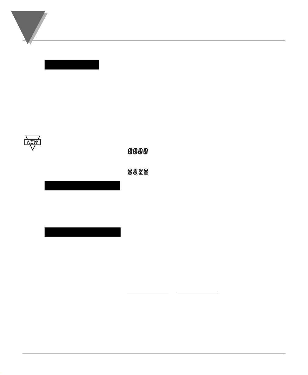
* 4-digit three color Programmable “Big” LED display
or 4-digit, Standard LED Display
* NEMA 4 / Type 4 Front Bezel
* ±0.03 % accuracy
* 8 DC input ranges: 0-100 mV, ±50 mV, 0-5 V, 1-5 V,
0-10 V, ±5 V, 0-20 mA, and 4-20 mA
* 5, 10, 12, or 24 Vdc sensor excitation
* Peak detection
* Front panel and remote tare function
* Nonvolatile memory-no battery backup
* 115 or 230 Vac 50/60 Hz power supply or
10-32 Vdc or 26-56 Vdc
The following is a list of optional features:
* Dual 5 amp, form C relay outputs
* Scalable analog output
* Proportional control
* Easy setup for proportional control
Features with are for the “B” version which has three-color programmable
“Big” LED display - All segment characters shown are for the “B” version.
Note
☞
Page 14

2
About The Meter
4
2.3 AVAILABLE ACCESSORIES
Table 2-1. Accessories and Add-Ons
Add-On Options
FS Special Calibration/Configuration
SPC4 NEMA-4 Splash Proof Cover
SPC18 NEMA-4 Splash Proof Cover, NEW
Accessories
TP1A Trimplate panel adaptor.
Adapts DIN1A/DIN2A cases to larger panel cutouts
RP18 19-In. Rack Panel for one (1) 1/8 DIN instrument
RP28 19-In. Rack Panel for two (2) 1/8 DIN instruments
RP38 19-In. Rack Panel for three (3) 1/8 DIN instruments
Page 15
5
About The Meter
2
2.4 FRONT OF THE METER
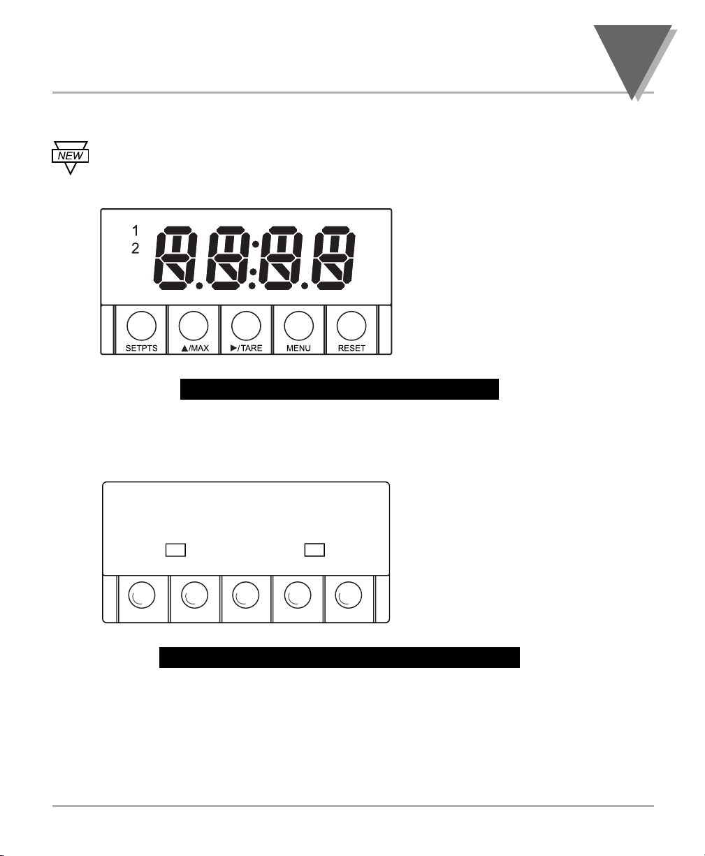
Figure 2-1 shows each part of the front of the three-color programmable
“Big” LED display meter (Version B).
Figure 2-1. Front-Panel with Big Display
Figure 2-2 shows each part of the front of the standard LED display meter.
Figure 2-2. Front-Panel wtih Standard Display
These meter display windows (both versions) light when appropriate:
1- Setpoint 1 status
2 - Setpoint 2 status
5 Pushbuttons for programming the meter.
//
••••
12
RESETMENU
TAREMAXSETPTS
Digital LED Display:
-
1.9.9.9 or 9.9.9.9 4-digit
three color programmable,
21 mm (0.83") high LED
display with programmable
decimal point.
Digital LED Display:
-
1.9.9.9. or 9.9.9.9.
14 segment, 13.8 mm
(0.54") high LED display
with programmable
decimal point.
Page 16

2
About The Meter
6
2.4 FRONT OF THE METER(Continued)
METER BUTTONS
SETPTS Button
In the Run Mode, this button will sequentially recall the previous setpoint settings. As
necessary, use the /MAX and /TARE buttons to alter these settings, then press the
SETPTS button to store new values.
Unless you press the SETPTS,
/TARE, or /MAX button within 20 seconds, the meter
will scroll to setpoint 2 and then to the Run Mode.
If the dual relay option is not installed or if the L.3=1 on the LK.CF menu,
pressing the SETPTS button will display the meter's firmware version.
/MAX Button
In the Run Mode, this button will recall the PEAK reading since the last press of the
RESET button.
In the Configuration Mode, press this button to change the value of the flashing digit
shown on the display and/or toggle between menu choices, such as R.1=T or R.1=N on
RD.CF menu. When configuring your setpoint values, press the /MAX button to
advance the flashing digit's value from 0 to 9 by 1.
/TARE Button
In the Run Mode press the /TARE button to tare your reading (zeroing) if you
configure the Reading Configuration bit R.1=T of the RD.CF menu. If you configure
R.1=N , the /TARE button has no function.
In the Configuration Mode, press the this button to scroll to the next digit.
Note
☞
Page 17
7
About The Meter
2
2.4 FRONT OF THE METER(Continued)
MENU Button
In the Run Mode, press the MENU button to terminate the current measuring process
and enter you into the Configuration Mode.
Only if you have not installed the lockout jumpers on the main board.
In the Configuration Mode, press the MENU button to store changes in the nonvolatile
memory and then advance you to the next menu item.
RESET Button
If you hard reset (press the MENU button followed by the RESET button) or power off/on
the meter, it shows RST, followed by PROC .
In the Run Mode, press the RESET button to reset tare, if any. The meter shows T.RST
and returns to the Run Mode.
In the Configuration Mode, press the RESET button once to review the previous menu.
Press the RESET button twice to perform a hard reset and return to the Run Mode.
In the Peak Mode, press the RESET button to reset peak values. The meter shows
PK.RS and returns to the Run Mode.
In the Setpoint Mode, press the RESET button to reset the latched setpoint. The meter
shows SP.RS and enters the Run Mode.
When in setpoint or Configuration Mode, if the meter shows 9999 or -1999
with all flashing digits, the value has overflowed. Press the
/MAX button
to start a new value.
Note
☞
Note
☞
Page 18
2
About The Meter
8
2.5 BACK OF THE METER
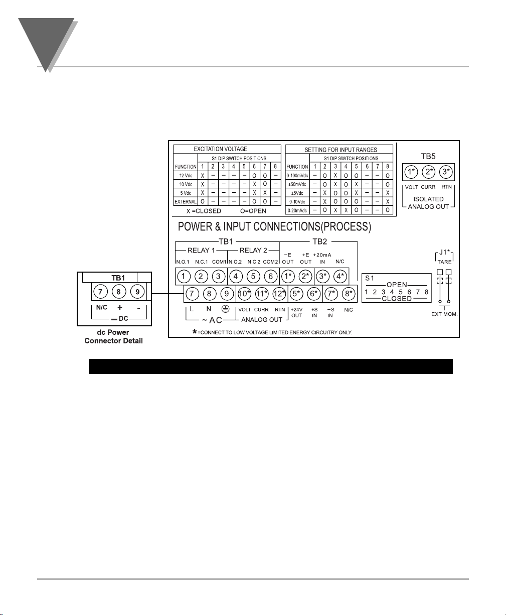
Figure 2-2 shows the label describing the connectors on the back of the meter. Table 2-2
on the following page gives a brief description of each connector at the back of the meter.
Figure 2-3. Connector Label (AC-Powered and DC-Powered Detail)
Page 19

9
About The Meter
2
2.5 BACK OF THE METER (Continued)
Table 2-2. Connector Description
Connector Description
TB1-1 Setpoint 1: Normally open (N.O.1) connection
TB1-2 Setpoint 1: Normally closed (N.C.1) connection
TB1-3 Setpoint 1: Common (COM1) connection
TB1-4 Setpoint 2: Normally open (N.O.2) connection
TB1-5 Setpoint 2: Normally closed (N.C.2) connection
TB1-6 Setpoint 2: Common (COM2) connection
TB1-7 AC line connection (no connections on DC-powered units)
TB1-8 AC neutral connection (+ Input on DC-powered units)
TB1-9 AC earth ground (DC-power return on DC-powered units)
TB1-10 Analog voltage output
TB1-11 Analog current output
TB1-12 Analog return
TB2-1 -E: Negative excitation connection from meter (5, 10, 12 V)
TB2-2 +E: Positive excitation connection from meter (5, 10, 12 V)
TB2-3 +20 mA connection for analog input
TB2-4 Not used.
TB2-5 +24 V output connection
TB2-6 +S: Positive signal input
TB2-7 -S: Negative signal input and return for +20 mA or +24 V
TB2-8 Not used
TB5-1 Isolated Analog Voltage Output
TB5-2 Isolated Analog Current Output
TB5-3 Isolated Analog Output Return
J1 (1-2) Remote tare connection with a momentary switch
Page 20
2
About The Meter
10
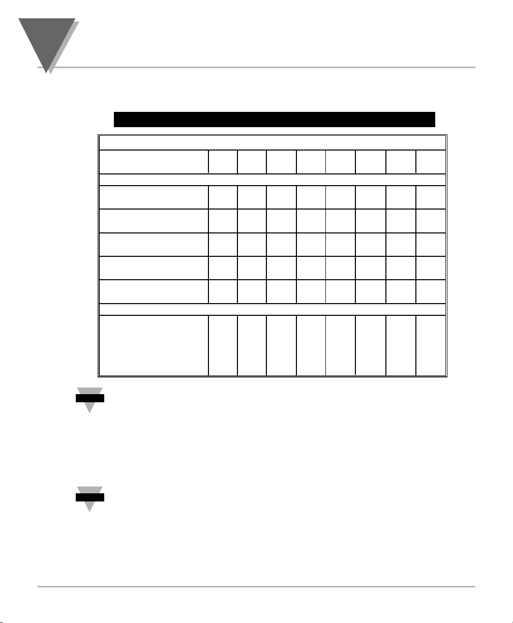
The DIP switches are located at the S1 position (refer to Figure 3-2). Use a small
instrument, such as a paper clip, to change the switches from open to closed. Table 2-3
lists DIP switch settings at the S1 position required to complete the setup of your meter.
Table 2-3. DIP Switch Positions/Input Range & Excitation
Function S1 DIP Switch Positions
C= Closed 1 2 3 4 5 6 7 8
O= Open
Settings for Excitation Voltage
Internal 5/10/12
excitation C - - - - - - External 5/10/12
excitation O - - - - O O Internal
12 Vdc excitation C - - - - O O Internal
10 Vdc excitation C - - - - C O Internal
5 Vdc excitation C - - - - C C -
Settings for Input Ranges
0-100 mV DC - O C O O - - O
±50 mV DC - O C O C - - O
±5 Vdc - C O O C - - C
0-10 Vdc - C O O O - - C
0-20 mA DC - O C C O - - O
The display must also be configured to the selected input type after setting
the DIP switches (see Section 4.1, Selecting the Input Type)
2.6 DISASSEMBLY
You may need to open up the meter for one of the following reasons:
• To check or change the 115 or 230 Vac power jumpers.
• To install or remove jumpers on the main board.
Disconnect the power supply before proceeding.
To remove and access the main board, follow these steps:
• Disconnect the main power from the meter.
• Remove the back case cover.
• Lift the back of the main board upwards and let it slide out of the case.
Note
☞
Note
☞
Page 21
11
Getting Started
3
SECTION 3. GETTING STARTED
Caution: The meter has no power-on switch, so it will be in operation as
soon you apply power.
If you power off/on the meter, or perform a hard reset (press the RESET button twice),
the meter shows RST , followed by PROC .
3.1 RATING/PRODUCT LABEL
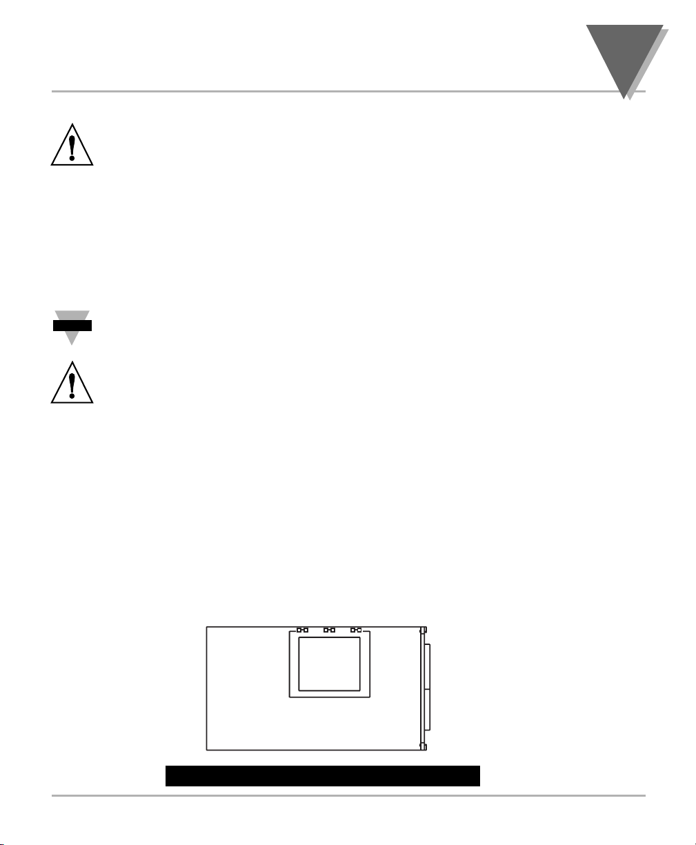
This label is located on top of the meter housing (refer to Figure 3-4).
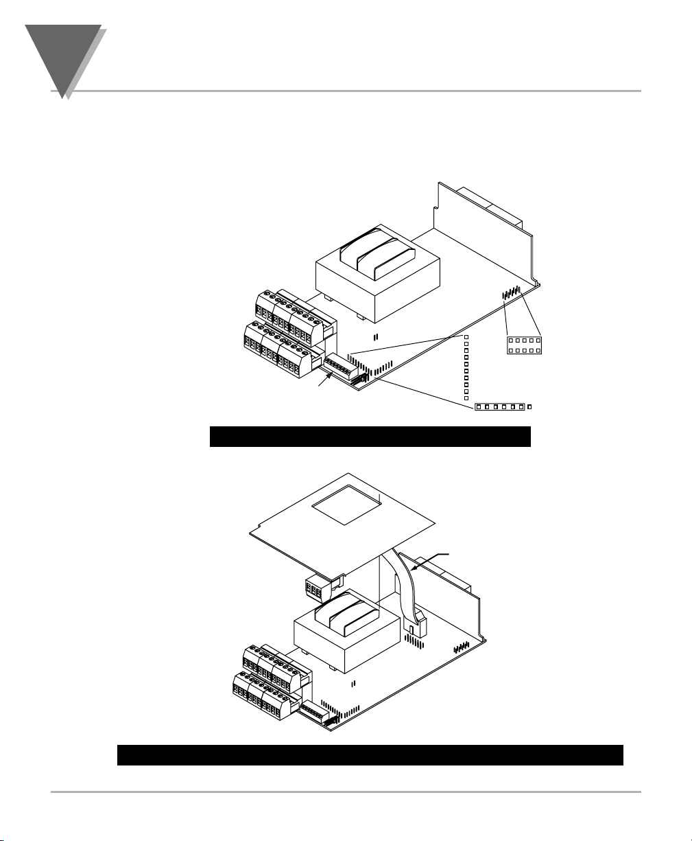
3.2 MAIN BOARD POWER JUMPERS (refer to Figure 3-1)
Important: If you want to change the Factory preset jumpers, do the
following steps; otherwise go to section 3.3.
Warning: Disconnect the power from the unit before proceeding. This
device must only be reconfigured by a specially trained electrician with
corresponding qualifications. Failure to follow all instructions and warnings
may result in injury!
1. Remove the main board from the case. Refer to Section 2.6.
2. Locate the solder jumpers W1, W2, and W3 (located near the edge of the main
board alongside the transformer).
3. If your power requirement is 115 Vac, solder jumpers W1 and W3 should be
wired, but jumper W2 should not. If your power requirement is 230 Vac,
solder jumper W2 should be wired, but jumpers W1 and W3 should not.
Note: W4 jumper is not used.
Figure 3-1 shows the location of solder jumpers W1 through W3.
Figure 3.1 Main Board Power Jumpers
Note
☞
W3 W2 W1
T1A
DISPLAY BOARD
Page 22
3
Getting Started
12
3.2 MAIN BOARD POWER JUMPERS (Continued)
Figure 3-2 shows the location jumper positions on the main board.
Figure 3-2. Main Board Jumper Positions
Figure 3-3. Upper Isolated Analog Output Option Board Installation
DISPLAY B
T1
MAIN BOARD
S4
TB1
{
TB2
{
S1
S2
J1
TP1
TP2
TP3
TP4
TP5
TP6
TP7
TP8
TP9
TP10
OARD
S3
S2
EDCBA
S3
Refer to
table 3-1
TP11
DCBA
Attach cable
to P1.
TB5
P1
Page 23

13
Getting Started
3
3.2 MAIN BOARD POWER JUMPERS (Continued)
S2 jumpers are used for testing purposes. Do not use as reading errors may result.
S3 jumpers are used for the following (refer to Figure 3-2):
* To enable or disable the front panel push-buttons
* To allow for an extremely low resistance load for analog output
* To disable the MENU button
* To perform calibration procedure
Test pins TP1 - TP11 are for testing purposes. Do not use as reading errors may result.
S4-A Factory default jumper installed.
Table 3-1. S3 Jumper Functions
Jumper Description
S3-A Install to enable front panel push-buttons.
Remove to disable all front panel push-buttons.
S3-B Removed. Install for factory calibration only.
S3-C Removed. Not used.
S3-D Removed. Not used.
S3-E If installed without S3-B, the MENU button locks out.
If you press the MENU button, the meter shows LOCK .
Page 24
3
Getting Started
14
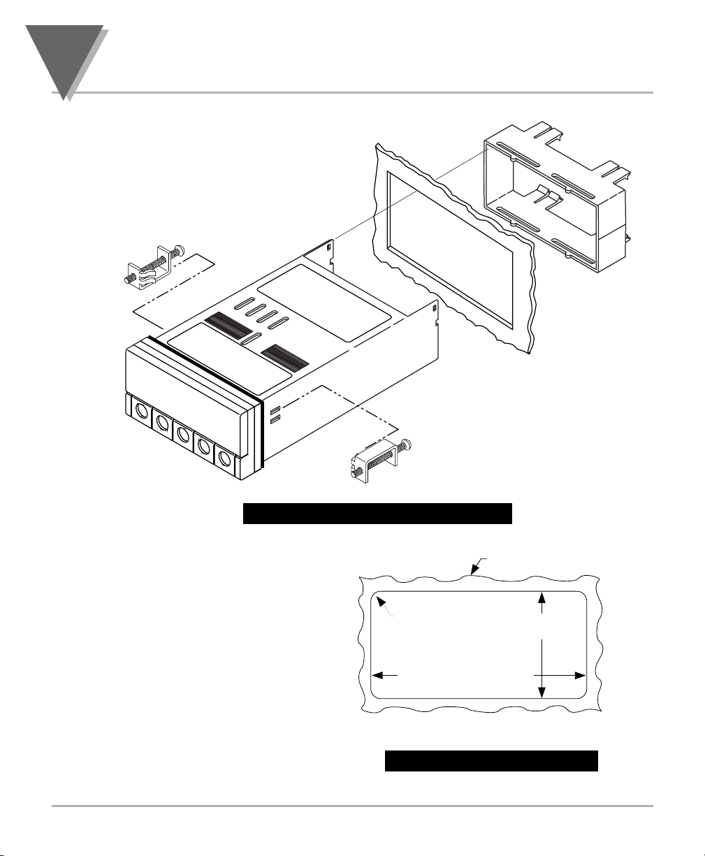
3.3 PANEL MOUNTING
Figure 3-4. Meter - Exploded View
1. Cut a hole in your panel, as
shown in Figure 3-4. For
specific dimensions refer to
Figure 3-5.
2. Insert the meter into the hole.
Be sure the front bezel gasket
is flush to the panel.
3. Slide on mounting bracket to
secure.
4. Proceed to Section 3.4 to
connect your sensor input and
main power.
Figure 3-5. Panel Cut-Out
CONNECTOR
LABEL
REAR COVER
(REMOVED)
PANEL
CUT-OUT
"NEW" STYLE
MOUNTING
BRACKET
PRODUCT
LABEL
GASKET
FRONT BEZEL
CASE
"OLDER" STYLE
MOUNTING
BRACKET 2 PCS
PANEL THICKNESS
6,4 (.25) MAX
0,8 (.03) MIN
1,5
R(.06)
4 PLCS
45,00 + 0,61/-0,00
(1.772 + .024/–.000)
92,00 + 0,81/–0,00
(3.622 + .032/–.000)
NOTE: Dimensions in Millimeters (Inches)
Page 25
15
Getting Started
3
3.4 CONNECTING SENSOR INPUTS
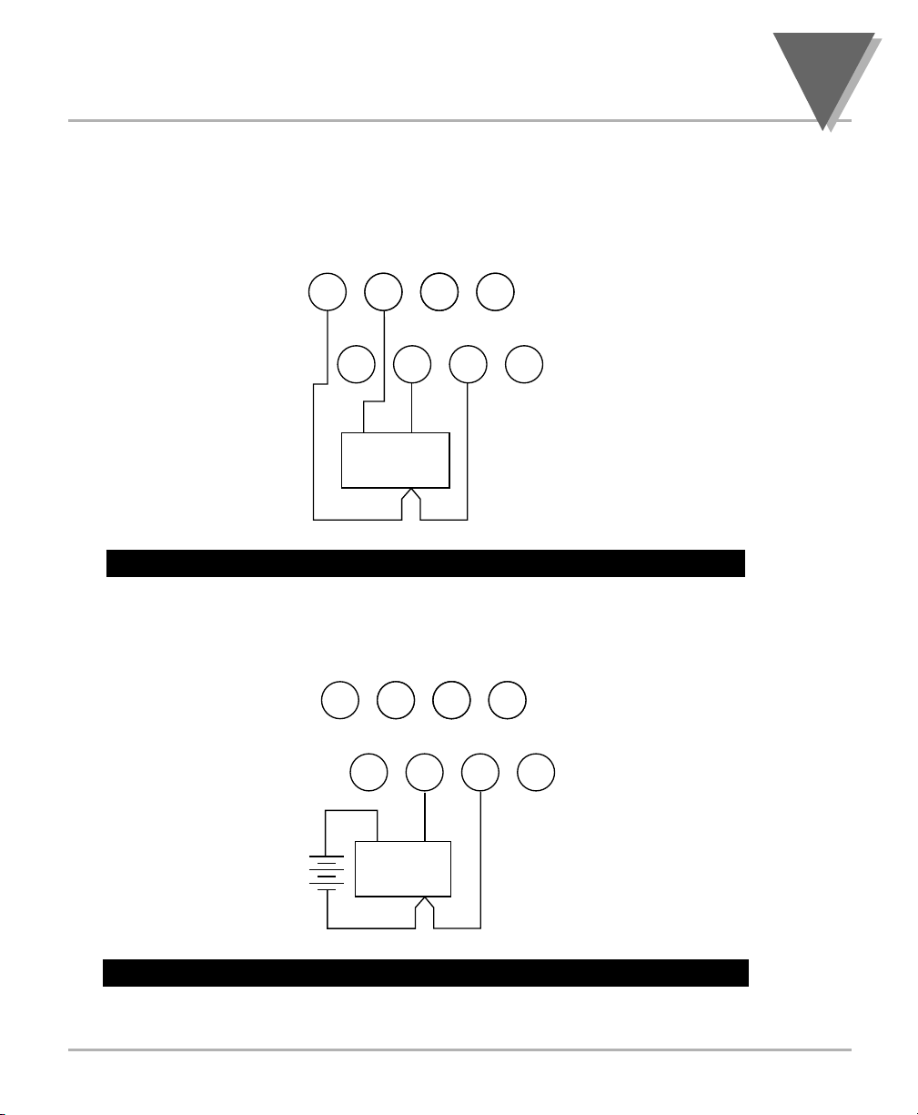
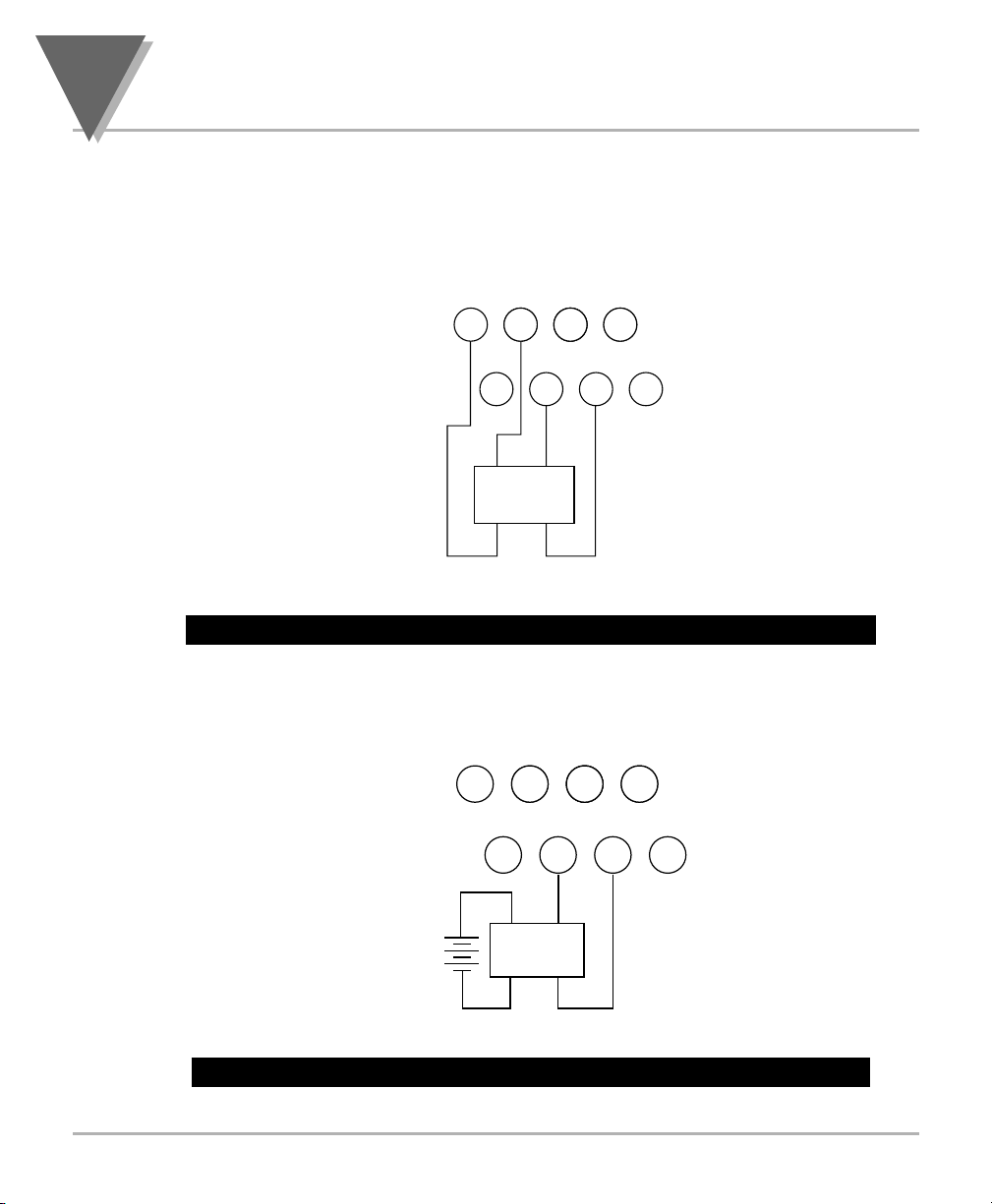
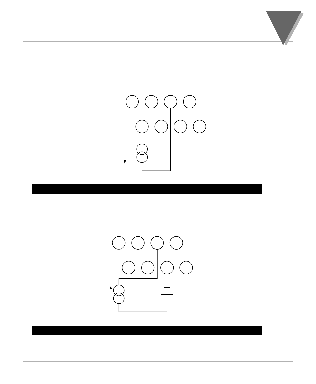
Figures 3-6 through 3-12 describe how to connect your sensors.
Figure 3-6. 3-Wire DC Input Connections with Internal Excitation
Figure 3-7. 3-Wire DC Input Connections with External Excitation
TB2
-E +E +20mA N/C
1234
+24V +S -S N/C
5678
EXC SIG
COM
TB2
-E +E +20mA N/C
1234
+24V +S -SN/C
5678
+
EXTERNAL
SUPPLY
++
-
--
Page 26
3
Getting Started
16
3.4 CONNECTING SENSOR INPUTS (Continued)
Figure 3-8. 4-Wire DC Input Connections with Internal Excitation
Figure 3-9. Wire DC Input Connections with External Excitation
TB2
-E +E +20mA N/C
1234
+24V +S -S N/C
5678
+-+
VOLTAGE
-
EXCITATION OUTPUT
TB2
-E +E +20mA N/C
1234
+24V +S -SN/C
5678
+
++
EXTERNAL
SUPPLY
-
--
SENSOR
OUTPUT
Page 27
17
Getting Started
3
3.4 CONNECTING SENSOR INPUTS (Continued)
Figure 3-10. DC Current Input Connections with Internal Excitation
Figure 3-11. DC Current Input Connections with External Excitation
TB2
-E +E +20mA N/C
1234
+24V +S -S N/C
5678
4-20mA
Transmitter
(+)
(-)
TB2
-E +E +20mA N/C
1234
+24V +S -S N/C
5678
4-20mA
Transmitter
(-)
(+)
EXTERNAL
SUPPLY
+
Page 28
3
Getting Started
18
3.4 CONNECTING SENSOR INPUTS (Continued)
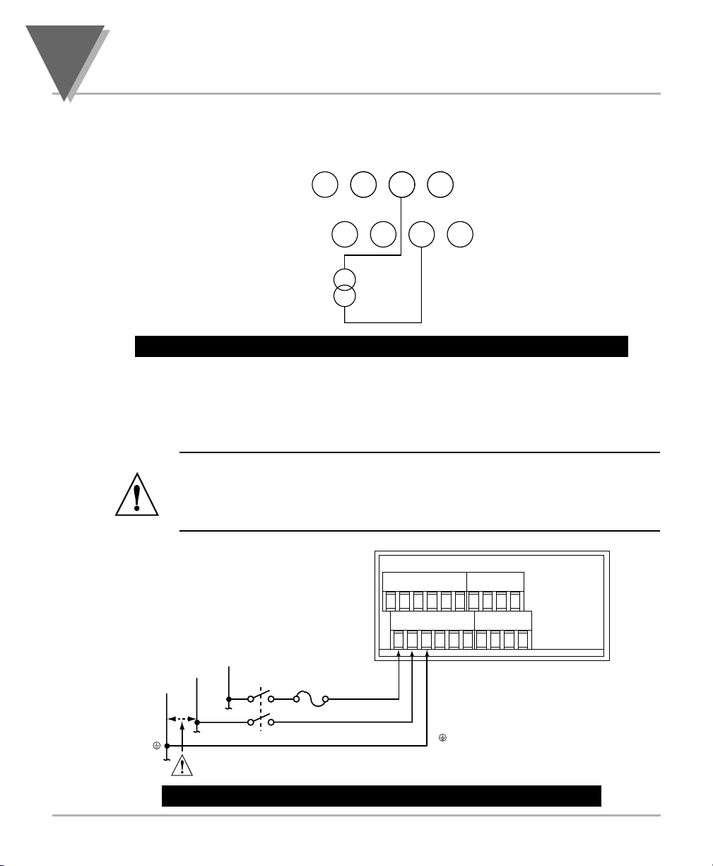
Figure 3-12. DC Current Input Connections with Current Source
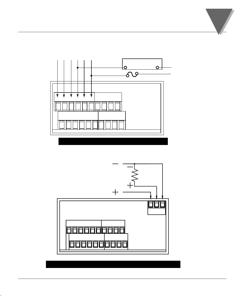
3.5 CONNECTING MAIN POWER
Connect the AC main power connections as shown in Figure 3-13.
WARNING: Do not connect AC power to your device until you have
completed all input and output connections. This device must only be
installed by a specially trained electrician with corresponding qualifications.
Failure to follow all instructions and warnings may result in injury!
Figure 3-13. Main Power Connections - AC Powered Unit
TB2
-E +E +20mA N/C
1234
+24V +S -SN/C
5678
(+)
MAX. 20mA
(-)
TB1 TB2
1234 12 3456
78910 56 7811 12
NEUTRAL
EARTH
LINE
SWITCH
Check for proper Earth grounding in the power
distribution system (single phase).
FUSE
GREEN WIRE
(L) LINE
(N) NEUTRAL
AC Power
EARTH GROUND
Page 29
19
Getting Started
3
3.5 CONNECTING MAIN POWER (Continued)
Table 3-2 shows the wire color and respective terminal connections for both USA and
Europe.
Table 3-2. Main Power Connection - AC Powered Unit
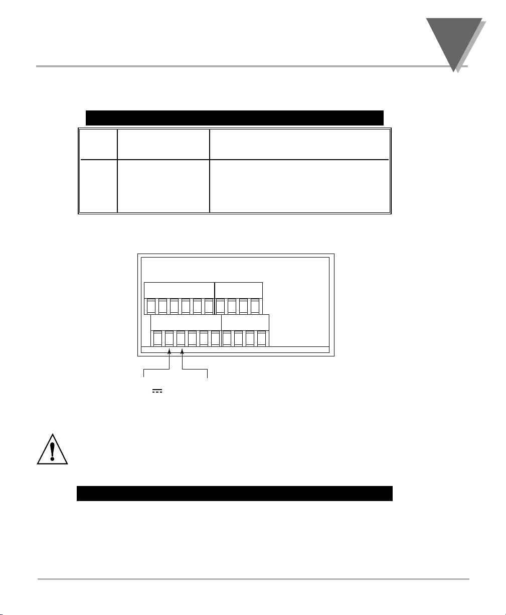
Connect the DC main power connections as shown in Figure 3-14.
When using DC power, refer to the Table 8-1 Color Chart in the Specifications
Section for Display Color, Intensity, Excitation Voltage and Current, and
Analog Output Isolated Option. Failure to use proper ratings may result in
damaging the unit.
Figure 3-14. Main Power Connections - DC Powered Unit
WIRE COLORS
TB1 AC POWER EUROPE USA
7 ~ AC Line Brown Black
8 ~ AC Neutral Blue White
9 ~ AC Earth Green/Yellow Green
TB1 TB2
1234 12 3456
78910 56 7811 12
+ DC
DC POWER
- DC
Page 30
3
Getting Started
20
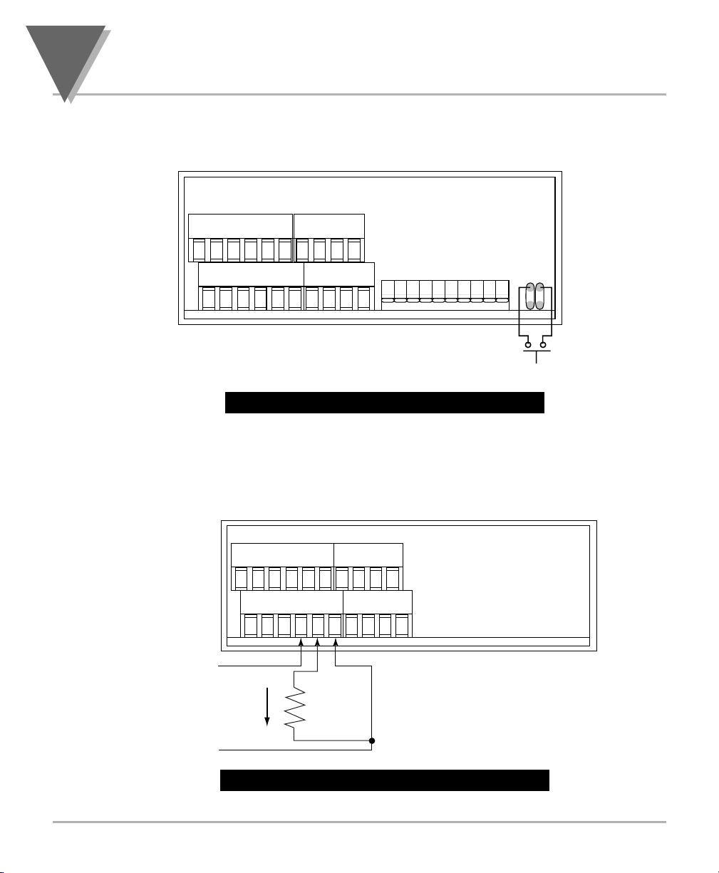
3.6 CONNECTING EXTERNAL TARE SWITCH
Connect external tare connections as shown in Figure 3-15.
Figure 3-15. External Tare Connections
3.7 CONNECTING ANALOG AND RELAY OUTPUTS
If you have purchased a meter with analog or dual relay or isolated analog output, refer
to the following drawings for output connections.
Figure 3-16. Analog Output Connections
TB1 TB2
1234 123456
78910 567811 12
S1
OPEN
CLOSED
EXTERNAL TARE SWITCH
J1
1 2
3 4
TB1 TB2
1234 123456
78910 567811 12
+
ANALOG
VOLTAGE
0-10V dc
+
-
ANALOG
CURRENT
0-20mA
or
4-20mA
ANALOG
RTN
-
Page 31
21
Getting Started
3
3.7 CONNECTING ANALOG AND RELAY OUTPUTS (Continued)
Figure 3-17. Relay Output Connections.
Figure 3-18. Isolated Analog Output Connections.
Relay 1 Relay 2
N.O.1
}
N.C.1
COM1
N.O.2
}
N.C.2
COM2
NO2
COM2
EXTERNAL LOAD
FUSE
N
L
TB1
123456
789101112
TB1 TB2
1234 1234
TB2
1234
5678
0—10VDC
56
0—20mA
OR
4—20mA
12 3
TB5
789101112
5678
Page 32
4
Configuring The Meter
22
SECTION 4. CONFIGURING THE METER
Refer to Table 6-1 for a summary list of menu configuration.
4.1 SELECTING THE INPUT TYPE INPT
To select your appropriate input type signal, follow these steps:
Before proceeding, set the input DIP switch settings at the back of your
meter. (Refer to Table 2-3).
1. Press the MENU button. The meter shows INPT.
2. Press the ∂TAR E button. The meter flashes one of the following:
• 0-20 (for 4-20 mA dc) (Default)
• 100M (for 0-100 mV dc)
• ±50M (for ±50 mV dc)
• 10V (for 0-10 Vdc)
• ±5V (for ±5 Vdc)
3. Press the ßMAX button to scroll through available choices.
4. Press the MENU button to store your choice. The meter momentarily shows
STRD , followed by DEC.P (Decimal Point).
Note
☞
Note
☞
Page 33
23
Configuring The Meter
4
4.2 SELECTING A DECIMAL POINT POSITION DEC.P
Refer to Table 6-1 for a summary list of menu configuration.
To select a decimal point display position, follow these steps:
1. Press the MENU button until the meter shows DEC.P .
2. Press the ∂TARE button. The meter shows one of the following:
• FFF.F
• FF.FF
• F.FFF
• FFFF
(
Default
)
3. Press the ßMAX button to scroll between available choices.
4. Press the MENU button to store your choice. The meter momentarily shows
STRD , followed by the next menu RD.S.O (Reading Scale and Offset). Or you can
press the RESET button to abort and go back to the DEC.P menu.
4.3 SELECTING READING SCALE AND OFFSET RD.S.0
Refer to Table 6-1 for a summary list of menu configuration.
To scale the meter to show readings in engineering units. There are two methods. One
method is to scale with known inputs. Another method is to scale without known inputs:
you calculate input values based on the transducer specifications and manually enter
them through the keyboard.
Note
☞
Note
☞
Page 34
4
Configuring The Meter
24
4.3.1 Scaling with Known Loads (On-Line Calibration)
For maximum resolution, find the maximum signal that will be applied to the
meter input.
• For regular voltage input, refer to the main body of Table 4-1.
• For millivolt or milliamp input, refer to the main body of Table 4-2.
Set the DIP switch positions as indicated at the top of either Table 4-1 or 4-2. The
numbers 1 through 8 in the top row of either table represent dip switches 1 through 8,
and the O, C or X directly below the number indicates the correct position of each switch.
• ‘O' Switch should be open or up.
• ‘C' Switch should be closed or down.
• ‘X' Switch is used to control excitation (refer to Table 2-3 to determine correct
position of these switches).
Once Dip switches have been positioned correctly, apply power. Proceed to the RD.CF
(Reading Configuration) and set R2 equal to the value in the right hand column of the
chart.
Table 4-1. Range Selection Dip Switch Positions For Regular Voltage Input
Table 4-2. Range Selection Dip Switch Positions For Millivolt/ Milliamp Input
Table 4-1. Range Selection Dip Switch Positions For Regular Voltage Input
Table 4-2. Range Selection Dip Switch Positions
For Millivolt and Milliamp Input
p
* Reading Configuration
12345678 12345678 12345678 RD.CF*
XOCOOXX0 XOCOCXX0 XOCCOXX0 R2=
0 - 100 mV ±50 mV 0 - 20 mA 4
0 - 50 mV ±50 mV 0 - 10 mA 3
0 - 30 mV ±30 mV 0 - 6 mA 2
0 - 20 mV ±20 mV 0 - 4 mA 1
0 - 10 mV ±10 mV 0 - 2 mA 0
12345678 12345678 RD.CF*
XCOOOXXC XCOOCXXC R2=
0 - 10 V ±5 V 4
0 - 5 V ±5 V 3
0 - 3 V ±3 V 2
0 - 2 V ±2 V 1
0 - 1 V ±1 V 0
Note
☞
Page 35
25
Configuring The Meter
4
4.3.1 Scaling with Known Loads (On-Line Calibration) (Continued)
To scale with known inputs: apply known loads to a transducer connected to a meter, or
simulate the transducer output with a voltage or current simulator. To scale with known
inputs, follow these steps:
1. Apply a known load equal to approximately 0% of the transducer range.
2. Press the MENU button until the meter shows RD.S.O .
3. Press the ∂TARE button. The meter shows IN1 (Input 1).
IN1 (Input 1) is the unscaled display reading at minimum input.
4. Press the ∂TARE button again. The meter shows last stored value for Input 1.
5. Press the ∂TARE button once more. The meter shows the actual signal being
received.
6. Press the MENU button to store this value as IN1 (Input 1). The meter shows
RD1 (Read 1).
RD1 (Read 1) is the desired display reading at Input 1.
7. Press the ∂TARE button. The meter shows the last stored value for Read 1.
8. Press the ßMAX button to change the value of your digits.
9. Press the ∂TARE button to scroll horizontally to the next digit.
10. Press the MENU button to store value as RD1 . The meter shows IN!2 (Input 2).
IN!2 (Input 2) is the unscaled display reading at maximum input.
Note
☞
Note
☞
Note
☞
Page 36

4
Configuring The Meter
26
4.3.1 Scaling with Known Loads (On-Line Calibration) (Continued)
11. Apply a known load equal to approximately 100% of the transducer range.
12. Press the ∂TARE button again. The meter shows the last stored value for Input 2.
13. Press the ∂TARE button once more. The meter shows the actual signal being
received.
14. Press the MENU button to store Input 2 value. The meter shows RD!2 (Read 2).
RD!2 (Read 2) is the desired display reading at input 2.
15. Press the ∂TARE button. The meter shows the last stored value for Read 2.
16. Press the ßMAX button to change the value of your digits.
17. Press the ∂TARE button to scroll horizontally to the next digit.
18. Press the MENU button to store value as RD!2 (Read 2). The meter momentarily
shows STRD , followed by RD.CF . Meter scaling is now complete.
Note
☞
Page 37
27
Configuring The Meter
4
4.3.2 Scaling Without Known Loads
To scale without known inputs, calculate input values based on the transducer
specifications and manually enter them on the front-panel pushbuttons. The following
example assumes a pressure transducer with these specifications:
Pressure Range: 0 to 2000 PSI
Output Span: 1 to 5 Vdc
1. Determine the correct values for IN1 and IN!2 based on the transducer
specifications. In most cases, RD1 & RD!2 are equal to the minimum and
maximum of the transducer output span. The example assumes RD1 & RD!2 are
equal to the pressure range of the transducer (RD1 = 0000 and RD!2 = 2000).
Calculate IN1 and IN!2 using the transducer output span and the following
equation:
IN = (Sensor Output) x (Natural Gain) x (Multiplier).
Table 4-3. Natural Gain
2. Determine the multiplier by the Input Resolution setting (R.2 in the RD.CF menu)
and the input range selected. Typically R.2=4 is suitable for most applications.
Table 4-4. Input Resolution Multiplier
Input Range R.2=4 R.2=3 R.2=2 R.2=1 R.2=0
0 to 100 mV 1.000 2.000 3.333 5.000 10.00
0 to 10 V 1.000 2.000 3.333 5.000 10.00
0 to 20 mA 1.000 2.000 3.333 5.000 10.00
± 50 mV 1.000 1.000 1.667 2.500 5.000
± 5 V 1.000 1.000 1.667 2.500 5.000
Input Range Span Units Natural Gain
0 to 100 mV Millivolts 100 cts/mV
±50 mV Millivolts 40 cts/mV
0 to 10 V Volts 1000 cts/V
± 5 V Volts 400 cts/V
0 to 20 mA Milliamps 500 cts/mA
Page 38

4
Configuring The Meter
28
4.3.2 Scaling Without Known Loads (Continued)
3. Determine IN1 & IN!2 input range and resolution. The example selects the 0 to
10 V range and 10 uV resolution (R.2=4 ).
Example: IN1 = (1 Volt) x (1000 cts/v) x (1.000) = 1000
IN!2 = (5 Volt) x (1000 cts/v) x (1.000) = 5000
RD1 = 0000
RD!2 = 2000
4. Press MENU button until the meter shows RD.S.O .
5. Press the ∂∂TARE button. The meter shows IN1 .
6. Press the ∂∂TARE button again, the meter shows the last Input 1 value, with the
fourth digit flashing.
7. Press the ßßMAX button to change the value of your digits.
8. Press the ∂∂TARE button to scroll horizontally to the next digit.
9. Press the MENU button to store this value. The meter shows RD1 .
10. Press the ∂TARE button. The meter shows the last value for read 1.
Repeat steps 7, 8 and 9 until RD1 , IN!2 and RD!2 have been displayed, verified,
changed (if necessary) and stored.
4.4 USING READING CONFIGURATION RD.CF
Refer to Table 6-1 for a summary list of menu configuration.
You may use Reading Configuration RD.CF to configure your meter for the following:
• To enable or disable the front panel tare
• To set the input resolution of your meter
• To display the filtered/unfiltered signal input value
Note
☞
Page 39

29
Configuring The Meter
4
4.4.1 Enabling or Disabling the Front-Panel Tare
To enable or disable the front-panel tare, follow these steps:
1. Press the MENU button until RD.CF displays.
2. Press the ∂TARE button. The meter shows one of the following:
• R.1=T (Tare enabled) (Default)
• R.1=N (Tare disabled)
3. Press the ßMAX button to view last stored selection. Press the ßMAX button to
toggle between selections.
4. Press the ∂TARE button to select input resolution or press the MENU button to
store your selections. STRD momentarily displays, followed by COLR menu.
4.4.2 Setting Input Resolution
To set the input resolution of your meter, follow these steps:
1. Press the MENU button until RD.CF displays, then press the ∂TARE button twice.
or
Press the ∂TARE button from R.1 .
One of the following displays (default is R.2=4 ):
R.2=4 = 10 µV for Unipolar inputs. 25 µV for Bipolar inputs
R.2=0 = 1 µV for Unipolar inputs. 5 µV for Bipolar inputs.
R.2=1 = 2 µV for Unipolar inputs. 10 µV for Bipolar inputs
R.2=2 = 3 µV for Unipolar inputs. 15 µV for Bipolar inputs.
R.2=3 = 5 µV for Unipolar inputs. 25 µV for Bipolar inputs
Example: 3 µV resolution means that if you input 0-30 mV, at 30 mV the display shows
9999 .
2. Press the ßMAX button to scroll through available selections.
3. Press the ∂TARE button to display the filtered/unfiltered signal input or press the
MENU button to store your selections. STRD momentarily displays, followed by
COLR menu.
Page 40

4
Configuring The Meter
30
4.4.3 Displaying the Filtered/Unfiltered Input Signal
To display the filtered/unfiltered signal input, follow these steps:
1. Press the MENU button until RD.CF displays, then press the ∂TARE button three
times.
or
Press the ∂TARE button from R.2.
One of the following displays:
• R.3=F (Filtered value) (Default)
• R.3=U (Unfiltered value)
2. Press the ßMAX button to toggle between available choices.
3. Press the MENU button to store your selections. STRD momentarily displays,
followed by COLR menu.
4.5 Selecting a Display Color COLR
Refer to Table 6-1 for a summary list of menu configuration.
Selecting “Display Color” is not active unless your meter is a Version “B”.
To select a display color, follow these steps:
1. Press the MENU button until the meter shows COLR.
2. Press the ∂TARE button. The meter shows one of the following:
• GRN
• RED
• AMBR
3. Press the ßMAX button to scroll between available choices.
4. Press the MENU button to store your choice. The meter momentarily shows
STRD , followed by the next menu S1.CF (Setpoint 1 Configuration). Or you can
press the RESET button to abort and go back to the RD.CF menu.
Note
☞
Page 41

31
Configuring The Meter
4
4.6 USING SETPOINT 1 CONFIGURATION S1.CF
Refer to Table 6-1 for a summary list of menu configuration.
Setpoint 1 Configuration S1.CF is not active unless your meter has dual relay output
capabilities. The LED's will display whether the S1.CF is active or not. You may use
Setpoint 1 Configuration S1.CF for the following:
• To set the setpoint's active band above or below your chosen value
• To select whether the setpoint operation is latched or unlatched
4.6.1 Setting Setpoint 1's Active Band
1. Press the MENU button until the meter shows S1.CF.
2. Press the ∂TARE button. The meter shows one of the following:
• S.1=A (Active above the setpoint) (Default)
• S.1=B (Active below the setpoint)
3. Press the ßMAX button to toggle between available choices.
4. Press the ∂TARE button to select if Setpoint 1 is latched or unlatched or press the
MENU button to store your selection.
4.6.2 Selecting if Setpoint 1 is Latched or Unlatched
1. Press the MENU button until S1.CF displays, then press the ∂TARE button twice.
or
Press the ∂TARE button from S.1 .
The meter shows one of the following:
• S.2=U Setpoint 1 to be unlatched (Default)
• S.2=L Setpoint 1 to be latched
2. Press the ßMAX button to toggle between available choices.
3. Press the MENU button to store your selection(s). The meter momentarily shows
STRD , followed by S2.CF (Setpoint 2 Configuration).
Note
☞
Page 42

4
Configuring The Meter
32
4.7 USING SETPOINT 2 CONFIGURATION S2.CF
Refer to Table 6-1 for a summary list of menu configuration.
Setpoint 2 Configuration S2.CF is not active unless your meter has dual relay output
capabilities. The LED's will display whether the S2.CF is active or not. You may use
Setpoint 2 Configuration S2.CF for the following:
• To set the setpoint's active band above or below your chosen value
• To select whether the setpoint operation is latched or unlatched
4.7.1 Setting Setpoint 2's Active Band
1. Press the MENU button until the meter shows S2.CF .
2. Press the ∂TARE button. The meter shows one of the following:
• S.1=A (Active above the setpoint) (Default)
• S.1=B (Active below the setpoint)
3. Press the ßMAX button to toggle between available choices.
4. Press the ∂TARE button to select if Setpoint 2 is latched or unlatched or press
the MENU button to store your selection and enter S1.DB (Setpoint 1 Deadband)
4.7.2 Selecting if Setpoint 2 is Latched or Unlatched
1. Press the MENU button until S2.CF displays, then press the ∂TARE button twice.
or
Press the ∂TARE button from S.1.
The meter shows one of the following:
• S.2=U Setpoint 2 to be unlatched (Default)
• S.2=L Setpoint 2 to be latched
2. Press the ßMAX button to toggle between available choices.
3. Press the MENU button to store your selection(s). The meter momentarily shows
STRD , followed by S1.DB (Setpoint 1 Deadband).
Note
☞
Page 43
33
Configuring The Meter
4
4.8 SETTING THE SETPOINT 1 DEADBAND S1.DB
Refer to Table 6-1 for a summary list of menu configuration.
Setpoint 1 Deadband S1.DB is not active unless your meter has dual relay output
capabilities. The LED's will display whether the S1.DB is active or not. The Setpoint 1
Default deadband is 0003. To change the deadband (hysteresis) of Setpoint 1, follow
these steps:
1. Press the MENU button until the meter shows S1.DB .
2. Press the ∂TARE button. The meter shows the last previously stored 4-digit
number (0000 through 9999) with flashing 4th digit.
3. Press the ßMAX button to change the value of the flashing digit. If you continue to
press the ßMAX button, the flashing digit's value continues to change.
4. Press the ∂TARE button to scroll to the next digit.
5. Press the MENU button to store your selection. The meter momentarily shows
STRD , followed by S2.DB (Setpoint 2 Deadband).
4.9 SETTING THE SETPOINT 2 DEADBAND S2.DB
Refer to Table 6-1 for a summary list of menu configuration.
Setpoint 2 Deadband S2.DB is not active unless your meter has dual relay output
capabilities. The LED's will display whether the S2.DB is active or not. The Setpoint 2
default deadband is 0003. To change the deadband (hysteresis) of Setpoint 2, follow
these steps:
1. Press the MENU button until the meter shows S2.DB .
2. Press the ∂TARE button. The meter shows the last previously stored 4-digit
number (0000 through 9999) with flashing 4th digit.
3. Press the ßMAX button to change the value of the flashing digit. If you continue to
press the ßMAX button, the flashing digit's value continues to change.
4. Press the ∂TARE button to scroll to the next digit.
5. Press the MENU button to store your selection. The meter momentarily shows
STRD , followed by OT.CF (Output Configuration) if you have analog output
capabilities.
Note
☞
Note
☞
Page 44
4
Configuring The Meter
34
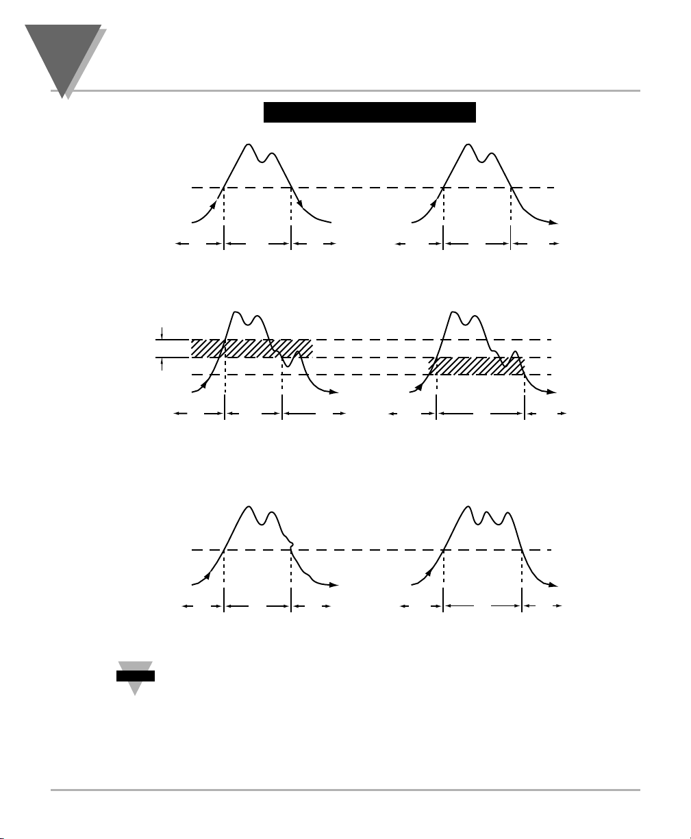
Figure 4-1. Alarm Example
To reset latched alarms you must:
1. Input a signal OUT of the alarm zone
2. Then press SETPTS and then, RESET button
SIGNAL
LEVEL
ON ONOFF
ACTIVE BELOW ACTIVE ABOVE
DEADBAND
SIGNAL
LEVEL
ON
NOTE: DEADBAND WORKS AS HYSTERISIS
SIGNAL
LEVEL
OFF
ACTIVE BELOW
WITH DEADBAND 3
ON
ON
OFF OFF
ON
ONOFF OFF
ACTIVE ABOVE
WITH DEADBAND 3
SETPOINT
3
SETPOINT
3
SETPOINT
Note
ON ON ON ON ON
ACTIVE BELOW LATCHED ACTIVE ABOVE LATCHED
☞
OFF
Page 45

35
Configuring The Meter
4
4.10 USING OUTPUT CONFIGURATION OT.CF
Refer to Table 6-1 for a summary list of menu configuration.
Output Configuration OT.CF is not active unless your meter has analog output
capabilities. The menu will display whether analog output is present or not. Analog
output must be ordered at the time of purchase.
Use Output Configuration OT.CF to select the following:
• To enable or disable the analog output
• To select if the analog output is current or voltage
• To select if the analog output is regular or proportional
4.10.1 Enabling or Disabling the Analog Output
To enable or disable the analog output, follow these steps:
1. Press the MENU button until the meter shows OT.CF.
2. Press the ∂TARE button. The meter shows one of the following:
• O.1=E (Analog output enabled) (Default)
• O.1=D (Analog output disabled)
3. Press the ßMAX button to toggle between available choices.
4. Press the ∂TARE button to select analog output as current or voltage or press the
MENU button to store your selection and enter OT.S.O (Output Scale and Offset).
Note
☞
Page 46

4
Configuring The Meter
36
4.10.2 Selecting Analog Output as Current or Voltage
1. Press the MENU button until it shows OT.CF, then press the ∂TARE button twice.
or
Press the ∂TARE button from 0.1.
The meter shows one of the following:
• O.2=C (Analog output = current) (Default)
• O.2=V (Analog output = voltage)
2. Press the ßMAX button to toggle between available choices.
3.
Press the ∂TARE button to select analog output or proportional control or press the
MENU button to store your selection and enter OT.S.O (Output Scale and Offset).
4.10.3 Selecting Analog Output or Proportional Control
Use this section to select if the meter will transmit an analog signal
proportional to the display readings, or proportional to the error signal between
the display reading and Setpoint 1.
Proportional Control Analog Option is not available for models without Relay Option.
1. Press the MENU button until it shows OT.CF , then press the ∂TARE button twice.
or
Press the ∂TARE button from 0.2.
The meter shows one of the following:
• O.3=A (Analog output is regular) (Default)
• O.3=P (Analog output is proportional)
2. Press the ßMAX button to toggle between available choices.
Note
☞
Page 47

37
Configuring The Meter
4
4.10.3 Selecting Analog Output or Proportional Control (Continued)
3a. If you select O.3=A, press the MENU button to store your selection. The meter
momentarily shows STRD , followed by OT.S.O (Output Scale and Offset).
3b. If you select O.3=P, press the ∂TARE button. The meter shows one of the
following:
• O.4=D (Proportional analog output is DIRECT ACTING)
• O.4=R (Proportional analog output is REVERSE ACTING).
4. Press the ßMAX button to toggle between available choices.
5. Press the MENU button to store your selections. The meter momentarily shows
STRD , followed by P.BND (Proportional Band).
Additionally, if you select O.2=V (Analog output to be voltage), press the ∂TARE
button. One of the following displays:
• O.5=F (Proportional 0-10 V analog output)
• O.5=H (Proportional 0-5 V analog output).
6. Press the ßMAX button to toggle between available choices.
7. Press the MENU button to store your selections. The meter momentarily shows
STRD , followed by P.BND (Proportional Band).
Page 48
4
Configuring The Meter
38
38
4.11 SELECTING PROPORTIONAL BAND P.BND
Proportional Band P.BND is not active unless your meter has analog output and relay
capabilities. The menu will display whether analog output is present or not.
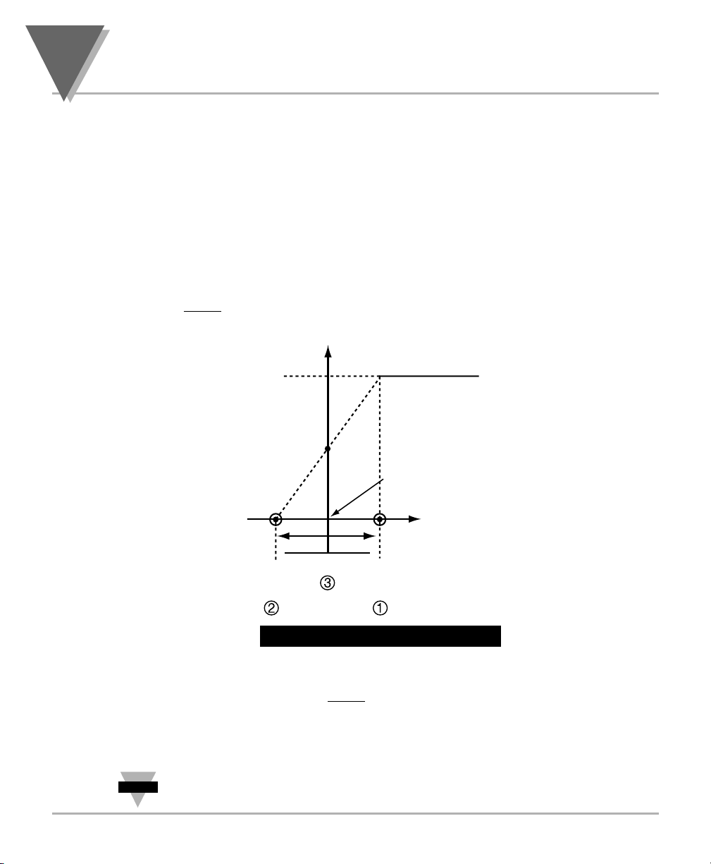
• A proportional controller's output is linearly proportional to the change of the
error signal, whenever the signal is within 2 prescribed values (Proportional
Band).
• There are three (3) points of interest on the proportional controller transfer
curve.
• The first is the magnitude of the error signal that drives the controller to
“full on
” (e.g. 20 mA out for 4-20 mA).
Figure 4-2. Controller Output
• The second point of interest is the magnitude of the error signal that drives
the controller output to “full off” (e.g. 4 mA out on 4-20 mA). These two (2)
points need not be equally spaced on either side of the zero error point.
• The third is the factor "Offset" and it is the output value of the
controller which causes zero error.
The above example illustrates the parameters for the 4-20 mA analog out,
likewise, analog voltage output will have these (3) points of interest.
CONTROLLER OUTPUT
100%
OFFSET
Zero error
0%
MIN
PROPORTIONAL BAND
4mA 20mA
MAX
ERROR=READING SETPOINT
Note
☞
Page 49

39
Configuring The Meter
4
39
4.11 SELECTING PROPORTIONAL BAND P.BND (Continued)
If A is the controller gain then,
Proportional Band = Max. out - Min. out
A
CONTROLLER OUT = A • ERROR + OFFSET
To select the proportional band for your proportional controller, follow these steps:
1. Press the MENU button until the meter shows P.BND .
If P.BND menu doesn’t show, set 0.3=P on Menu OT.CF.
Remember to press ∂TARE when OT.CF is displayed until 0.3=A , then
press ßMAX, unit will show 0.3=P . Pressing the MENU button will store the
selection.
2. Press the ∂TARE button. The meter shows last previously stored 4-digit number
(0000 through 9999) with flashing 4th digit.
3. Press the ßMAX button to change the value of the flashing digit. If you continue to
press the ßMAX button, the flashing digit's value continues to change.
4. Press the ∂TARE button to scroll to the next digit.
5. Press the MENU button to store your selection. The meter shows STRD , followed
by M.RST (Manual Reset).
Note
☞
Page 50
4
Configuring The Meter
404040
4.12 USING MANUAL RESET M.RST
Refer to Table 6-1 for a summary list of menu configuration.
Manual Reset M.RST is not active unless your meter has analog output and relay
capabilities. The menu will display whether analog output is present or not. This feature
allows you to offset the error that may occur with your setpoint. In order to determine the
amount of error, you must compare your display value to the Setpoint 1 value. The
difference between these two values (display - Setpoint 1) is the amount of error that you
may want to enter into Manual Reset M.RST . The value of M.RST must be less than
P.BND /2. Larger values will not be accepted and the meter will display ER4 (flashing).
1. Press the MENU button until M.RST displays.
This menu M.RST and P.BND will show up if 0.3=P on OT.CF.
2. Press the ∂TARE button. The meter shows the last previously stored 4-digit
number (-1999 through 9999) with flashing 4th digit.
3. Press the ßMAX button to change the value of the flashing digit. If you continue to
press the ßMAX button, the flashing digit's value continues to change.
4. Press the ∂TARE button to scroll to the next digit.
5. Press the MENU button to store your selection. STRD momentarily displays,
followed by RST (Reset).
Note
☞
Note
☞
Page 51
41
Configuring The Meter
4
41
4.13 USING OUTPUT SCALE AND OFFSET OT.S.O
Refer to Table 6-1 for a summary list of menu configuration.
Output Scale and Offset OT.S .O is not active unless your meter has analog output
capabilities. The menu will display whether analog output is present or not. Output Scale
and Offset O T.S.O scales your analog output to be equal to the meter's display and/or
any engineering units you require. You may scale the output for direct (4-20 mA, 0-10 V,
etc) or reverse acting (20-4 mA, 10-0 V, etc).
1. Press the MENU button until OT.S.O displays.
2. Press the ∂TARE button. RD1 (Read 1) displays.
This is your first point of display reading.
3. Press the ∂TARE button again. The meter shows the last previously stored
4-digit number (-1999 through 9999) with flashing 4th digit.
4. Press the ßMAX button to change the digits.
5. Press the ∂TARE button to scroll to the next digit.
6. Press the MENU button to store your selection. OUT.1 (Output 1) displays.
This starting analog signal corresponds to your Read 1 display.
7. Press the ∂TARE button. Selected output displays.
If you select O.2=V for voltage, the maximum signal you may select is
10.00 for an 0-10 Vdc signal output. If you select O.2=C for current, the
maximum signal you may select is 20.00.
8. Press the ßMAX button to enter the Output 1 signal selection. If you continue to
press the ßMAX button, the flashing digit's value continues to change.
9. Press the ∂TARE button to scroll to the next digit.
10. Press the MENU button to store your selection. RD!2 (Read 2) displays.
This is your second point of display reading.
Note
☞
Note
☞
Note
☞
Note
Note
☞
☞
Page 52
4
Configuring The Meter
4242
4.13 USING OUTPUT SCALE AND OFFSET OT.S.O (Continued)
11. Press the ∂TARE button. The meter shows last previously stored 4-digit number
(-1999 through 9999) displays with flashing 4th digit.
12. Press the ßMAX button to change the value of the flashing digit. If you continue
to press the ßMAX button, the flashing digit's value continues to change.
13. Press the ∂TARE button to scroll to the next digit.
14.
Press the MENU button to store your selection. The meter shows OUT.2 (Output 2).
This analog signal should correspond to your Read 2 display.
15. Press the ∂TARE button. The meter shows selected output.
If you select O.2=V for voltage, the maximum signal you may select is 10.00
for an 0-10 Vdc signal output. If you select O.2=C for current, the maximum
signal you may select is 20.00 for a 0-20 or 4-20 mA DC signal output.
16. Press the ßMAX button to change the value of the flashing digit. If you continue to
press the ßMAX button, the flashing digit's value continues to change.
17. Press the ∂TARE button to scroll to the next digit.
18. Press the MENU button to store your selection. The meter momentarily shows
STRD , followed by LK.CF (Lockout Configuration).
WARNING: If the meter displays all flashing values on any item, the value
has overflowed. Press the ßMAX button to start new values.
Note
☞
Note
☞
Page 53

43
Configuring The Meter
4
43
4.14 USING LOCK OUT CONFIGURATION LK.CF
Refer to Table 6-1 for a summary list of menu configuration.
Use Lock Out Configuration LK.CF for the following:
• To enable or disable setpoint changes
• To enable or disable the RESET button in the Run Mode
• To enable or disable displaying the meter’s firmware version.
4.14.1 Enabling or Disabling the RESET button in the Run Mode
1. Press the MENU button until the meter shows LK.CF (after OT.S.O).
2.
Press the ∂TARE button. The meter shows one of the following:
• RS.=E To enable the RESET button in the Run Mode (Default)
• RS.=D To disable the RESET button in the Run Mode
3. Press the ßMAX button to toggle between available choices.
4. Press the MENU button to store the changes. The meter shows STRD if the new
value is different otherwise the meter shows BRIT and returns to the Run Mode.
4.14.2 Enabling or Disabling SETPOINT Changes
1. Press the MENU button until the meter shows LK.CF (after OT.S.O).
2. Press the ∂TARE button twice. The meter shows one of the following:
• SP.=E To enable setpoint changes (Default)
• SP.=D To disable setpoint changes
3. Press the ßMAX button to toggle between available choices.
4. Press the MENU button to store the changes. The meter shows STRD if the new
value is different otherwise the meter shows BRIT and returns to the Run Mode.
Note
☞
Page 54

4
Configuring The Meter
4444
4.14.3 SETPOINT Display Function: Firmware version or Setpoint value
1. Press the MENU button until the meter shows LK.CF (after OT.S.O ).
2. Press the ∂∂TARE button three times. The meter shows one of the following:
• L.3=0 SETPTS button will display setpoint values.
• L.3=1 SETPTS button will display the meter's firmware version.
3. Press the ßMAX button to toggle between the choices above.
4. Press the MENU button to store the changes. The meter shows STRD if the new
value is different otherwise the meter shows BRIT and returns to the Run Mode.
If your meter does not have the relay option, setpoint menu items above will
not be available and SETPTS button will always display the meter's firmware
version. These units will have +OL (overload) or +OPN memory indicated by
Alarm 1 & 2 LED displays. LEDs can be reset by pressing MENU then
RESET button or by Power OFF then ON.
4.15 USING DISPLAY BRIGHTNESS CONFIGURATION
Changing “Display Brightness” is not active unless your meter is a Version “B”.
1. Press the MENU button until the meter shows BRIT (after LKCF).
2. Press the ∂TARE button from BRIT. The meter shows one of the following:
• M.BrT Medium Brightness
• L.BrT Low Brightness
• H.BrT High Brightness (Default)
3. Press the ßMAX button to toggle between available choices.
4. Press the MENU button to store your selection. The meter momentarily shows
STRD followed by STRD, RST, PROC, then measured value.
Note
☞
Page 55
45
Display Messages
5
45
Display Messages
5
45
SECTION 5. DISPLAY MESSAGES
Table 5-1. Display Messages
MESSAGE DESCRIPTION
PROC Process Meter
RST Hard (Power On) Reset
INPT Input Type
DEC.P Decimal Point
RD.S.O Reading Scale and Offset
RD.CF Reading Configuration
COLR Display Color
S1.CF Setpoint 1 Configuration
S2.CF Setpoint 2 Configuration
S1.DB Setpoint 1 Deadband
S2.DB Setpoint 2 Deadband
P.BND Proportional Band
M.RST Manual Reset
ER4 Manual Reset Error
OT.CF Output Configuration
OT.S.O Output Scale and Offset
LK.CF Lock Out Configuration
BRIT Display Brightness
+OL + Overload Signal
-OL - Overload Signal
RS.OF Resolution Overflow
+999 Value Overflow in Setpoint/Menu & Peak Routines
-1999 Value Overflow in Setpoint/Menu & Peak Routines
ER1 2 Coordinate Format Programming Error
PEAK Peak Value
PK.RS Peak Reset
T.RS Tare Reset
SP.RS Reset Latched Alarms
SP1 Setpoint 1 Value
SP2 Setpoint 2 Value
R.OV.S Resolution Over Scale
V.-8.8 Firmware Version (where
8
is 0 ~ 9)
RUN Operating Mode
Page 56
6
Menu Configuration Displays
46464646
SECTION 6. MENU CONFIGURATION DISPLAYS
Not all menu items display on standard meters.
Table 6-1. Menu Configuration Displays
(Defaults in Bold and Italics)
MENU ∂TARE ßMAX
Show input choices: 100M
INPT
±50M
10V
±5V
0-20
(
Default
)
Show current decimal FFFF (Default
)
DEC.P
point position F.FFF
FF.FF
FFF.F
Reading Scale & Offset
Shows IN1
RD.S.O
Shows prior value entered and flashing digit. Changes the value
Scrolls to the next digit. of the flashing digit
• If
∂TARE is pressed, actual input
is shown and can not be changed
with ßMAX.
• If
ßMAX is pressed, unit can
scroll through digits with ∂TARE .
Enter new value and Shows prior value entered and flashing digit. Changes the value
show RD1 Scrolls to the next digit. of the flashing digit
Enter new value and Shows prior value entered and flashing digit. Changes the value
show IN2 Scrolls to the next digit. of the flashing digit
• If
∂TARE is pressed, actual input
is shown and can not be changed
with ßMAX.
• If
ßMAX is pressed, unit can
scroll through digits with ∂TARE .
Enter new value and Shows prior value entered and flashing digit. Changes the value
show RD2 Scrolls to the next digit. of the flashing digit
1
3
2
4
6
7
5
Page 57
47
Menu Configuration Displays
6
47
SECTION 6. MENU CONFIGURATION DISPLAYS (Continued)
Table 6-1. Menu Configuration Displays (Continued)
(Defaults in Bold and Italics)
MENU ∂TARE ßMAX
Reading Configuration
R.1= R.1=T (Tare enabled)
R.1=N (Tare disabled)
RD.CF
R.2= R.2=0
(1 µV resolution for unipolar
& 5 µV resolution for bipolar)
R.2=1 (2 µV resolution for unipolar
& 10 µV resolution for bipolar)
R.2=2 (3 µV resolution for unipolar
& 15 µV resolution for bipolar)
R.2=3 (5 µV resolution for unipolar
& 25 µV resolution for bipolar)
R.2=4 (10 µV resolution for
unipolar & 25 µV resolution
for bipolar)
Note: 3 µV resolution means if
your input is 0-30 mV, at 30 mV
the display shows 9999.
R.3= R.3=F (Filtered value)
R.3=U (Unfiltered value)
Show input choices:
GRN
(
Green
)
Display Color Selection
RED
(
Red
)
COLR
AMBR
(
Amber
)
S.1= S.1=A (Active above)
Setpoint 1 Configuration S.1=B (Active below)
S1.CF
S.2= S.2=U (Unlatched)
S.2=L (Latched)
S.1= S.1=A (Active above)
Setpoint 2 Configuration S.1=B (Active below)
S2.CF
S.2= S.2=U (Unlatched)
S.2=L (Latched)
Page 58
6
Menu Configuration Displays
48
SECTION 6. MENU CONFIGURATION DISPLAYS (Continued)
Table 6-1. Menu Configuration Displays (Continued)
(Defaults in Bold and Italics)
MENU ∂TARE ßMAX
Press to scroll to the Press to change the value of the
Setpoint 1 Deadband
next digit to the right flashing digit
S1.DB
Press to scroll to the Press to change the value of the
Setpoint 2 Deadband
next digit to the right flashing digit
S2.DB
0.1 = 0.1=E (Analog output is enabled)
Output Configuration
0.1=D (Analog output is disabled)
OT.CF
0.2 = 0.2=C (Analog output is current)
0.2=V (Analog output is voltage)
0.3 = 0.3=A (Regular analog output)
0.3=P (Proportional analog output)*
0.4 = 0.4=D (Proportional analog is direct acting)
shown if menu 0.3=P 0.4=R (Proportional analog is reverse acting)
0.5 = 0.5=F (Analog output is 0-10 Vdc)
shown if menu 0.2=V 0.5=H (Analog output is 0-5 Vdc)
* If you select 0.2V and 0.3=P , you may select your analog
output to be
0-10 V or 0-5 V by accessing submenu 0.5=F
or 0.5=H
.
*I
f 0.3=P , you may select your proportional output analog to be:
• Direct Acting 0.4=D: 4-20 mA, 0-5 V, 0-10 V
• Reverse Acting 0.4=R: 20-4 mA, 5 V-0 V, 10 V-0 V
Note
☞
Page 59

SECTION 6. MENU CONFIGURATION DISPLAYS (Continued)
Table 6-1. Menu Configuration Displays (Continued)
(Defaults in Bold and Italics)
49
Menu Configuration Displays
6
MENU ∂TARE ßMAX
P.BND Shows prior value entered. Changes the value
Proportional Band Scrolls to the next digit to the right. of the flashing digit
shown menu if 0.3=P
M.RST Shows prior value entered. Changes the value
Manual Reset Scrolls to the next digit to the right. of the flashing digit
shown menu if 0.3=P
Output Scale & Offset
Shows RD1
OT.S.O
Shows prior value entered and flashing digit. Changes the value
Scrolls to the next digit. of the flashing digit
Enter new value and Shows prior value entered and flashing digit. Changes the value
show OUT1 Scrolls to the next digit. of the flashing digit
Enter new value and Shows prior value entered and flashing digit. Changes the value
show RD2 Scrolls to the next digit. of the flashing digit
Enter new value and Shows prior value entered and flashing digit. Changes the value
show OUT2 Scrolls to the next digit. of the flashing digit
1
3
2
4
6
7
5
(
Shown if O.3=A in Output
Configuration Menu OT.CF
)
Page 60
6
Menu Configuration Displays
50
SECTION 6. MENU CONFIGURATION DISPLAYS (Continued)
Table 6-1. Menu Configuration Displays (Continued)
(Defaults in Bold and Italics)
M.BrT(Medium Brightness
)
Brightness Configuration
BRIT
L.BrT (Low Brightness)
H.BrT
(High Brightness)
Table 6-2. Run Mode
Displays
Table 6-2. Run Mode Displays
Display
∂∂
TARE
ßß
MAX RESET Description
Displays the Reset the Peak Reading
PEAK peak reading peak reading
and must be when in this
pressed again mode. Displays the
to return to the highest reading
normal
since last reset.
operating mode
without
resetting.
Press to Will reset your Tare Reset
T.RST
activate. tare when
viewing this
function.
Reset Latched
Alarms
SP.RS
Pressing the
RESET button
resets your
latched alarms.
MENU ∂TARE ßMAX
RS= RS=E (Enable RESET button in the Run Mode)
Lock Out Configuration
RS=D (Disable RESET button in the Run Mode)
LK.CF
SP= SP=E (Enable setpoint changes)
SP=D (Disable setpoint changes)
L3= L3=0
(SETPTS button display setpoint values)
L3=1 (SETPTS button display firmware version
V.-8.8
where8is 0~9)
Page 61
51
Setpoint Configuration Displays
7
51
SECTION 7. SETPOINT CONFIGURATION DISPLAYS
Table 7-1. Setpoint Configuration Displays
MENU
∂∂
TARE
ßß
MAX Description
SETPOINT 1
SP1 Press to scroll to Press to change Select from -1999
the next digit to the the value of the through 9999
right flashing digit
SETPOINT 2
SP2 Press to scroll to Press to change Select from -1999
the next digit to the the value of the through 9999
right flashing digit
Page 62
8
Specifications
52
SECTION 8. SPECIFICATIONS
SIGNAL INPUT
Input Ranges:
0-100 mV, ± 50 mV, 0-10 V, ± 5 V, 0-20 mA, 4-20 mA
Isolation: Dielectric strength to 2500V transient per 3mm spacing
based on EN 61010 for 260Vrms or DC working voltage
Noise Rejection: Normal Mode Rejection (NMR) = 60 dB
Common Mode Rejection (CMR) = 120 dB
Resistance: 100 Meg ohms for 100 mV or ±50 mV input range
1 Meg ohm for 10 V or +5 V input range
5 ohms for 20 mA current input range
“Big” Display:
4-digit, three color programmable 9-segment, LED 21 mm (0.83")
Symbol: (
-1.9.9.9~9.9.9.9
)
Standard Display: 4-digit, 14-segment LED, 13.8 mm (0.54”)
Symbol: (
-1.9.9.9. ~9.9.9.9.
)
ANALOG TO DIGITAL
Technique: Dual slope
Internal resolution: 15 bits
Read Rate: 3/sec Polarity Automatic
ACCURACY AT 25°C
Max Error Strain/Process: ±0.03% of reading, ±1 count
Span Tempco: 50 ppm/°C
Step Response: 1 sec
Warm Up to Rated Accuracy: 30 min
Excitation Voltage: AC
power units DC power units
24 V @ 25 mA,
Refer to Table 8-1
12 V @ 50 mA,
Color chart for DC Output
10 V @ 120 mA,
Excitation
5 V @ 60 mA
Load Regulation: 1.1%
Line Regulation: 0.02% per Vac
Page 63

53
Specifications
8
SECTION 8. SPECIFICATIONS (Continued)
ALARM OUTPUTS (if applicable)
2 Form "C" on/off relays. Configurable for latched and
unlatched by software.
Max current: 5 AMPS, resistive load
Max voltage: 250 Vac or 30 Vdc
ANALOG OUTPUT (if applicable)
Signal Type: Current or voltage
Signal Level: Current: 10 V max compliance at 20 mA output
Voltage: 20 mA max for 0-10 V output
Function: May be assigned to a display range or proportional
control output with Setpoint #1 when used as a control
output.
Linearity: 0.2%
Step Response Time: 2 - 3 seconds to 99% of the final value
ISOLATED ANALOG OUTPUT (TB5, if applicable)
Same as non-isolated analog output except isolated.
Signal Type: Current or voltage
Signal Level: Current: 10 V max compliance at 20 mA output
Voltage: 20 mA max for 0-10 V output
Function: May be assigned to a display range or proportional
control output with Setpoint #1 when used as a control
output.
Linearity: 0.2%
Step Response Time: 2 - 3 seconds to 99% of the final value
Isolation 130 Vrms working voltage, 1000 V/60sec Dielectric test
• Only one analog output is available on each unit and it must be factory
installed.
Note
☞
Page 64
8
Specifications
SECTION 8. SPECIFICATIONS (Continued)
INPUT POWER INFORMATION
~
AC units 115/230 V~(AC) +
9.5 W max, power consumption (Non-Isolated Analog Out)
11.0 W max, power consumption (Isolated Analog Out)
DC units 12-32 Vdc, 8W
External Fuse Required:
ENVIRONMENT
Operating temperature: 0° to 50°C (32° to 122°F)
Storage temperature: -40° to 85°C (-40° to 185° F)
Relative humidity: 90% at 40°C (non-condensing)
MECHANICAL
Panel cutout: 1/8 DIN 3.62 x 1.78" (45 x 92mm)
Weight: 1.27 lb (575 g)
Case material: Polycarbonate, 94 V-O UL rated
Protection: NEMA-4/Type 4 Front Bezel
(Refer to Table 8-1 below)
IEC 127-2/III
Power Fuse
115 V 125 mA @ 250 (T)
230 V 63 mA @ 250 (T)
UL 248-14 (Listed Fuse)
Power Fuse
115 V 175 mA @ 250 V Slow-Blow
230 V 80 mA @ 250 V Slow-Blow
10%, 50/60 Hz
54
Page 65
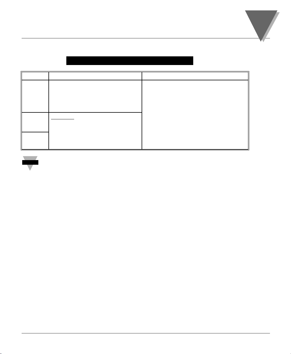
55
Specifications
8
SECTION 8. SPECIFICATIONS (Continued)
Table 8-1. COLOR CHART FOR DC POWER
COLOR HIGH BRIGHTNESS MEDIUM & LOW BRIGHTNESS
RED Sensor Excitation: Any combination of Sensor Excitation
24 V @ 25 mA, and Analog Output
12 V, 10 V, 5 V @ 35 mA Max 24 V @ 25 mA,
Analog Output: 12 V @ 35 mA Max
Non-Isolated option only 10 V@ 35 mA Max
5 V @ 35 mA Max
GREEN
Analog Output:
Non-Isolated options or
Isolated Analog option
AMBER
W
arning:
• Do not use Internal Excitation.
Use External Excitation.
•
Do not use Isolated Analog Output.
Use Non-Isolated Analog Ouput.
HIGH/LOW Brightness and AMBER are only available on Version “B” meters.
Standard display meters are MEDIUM Brightness.
Note
☞
Page 66
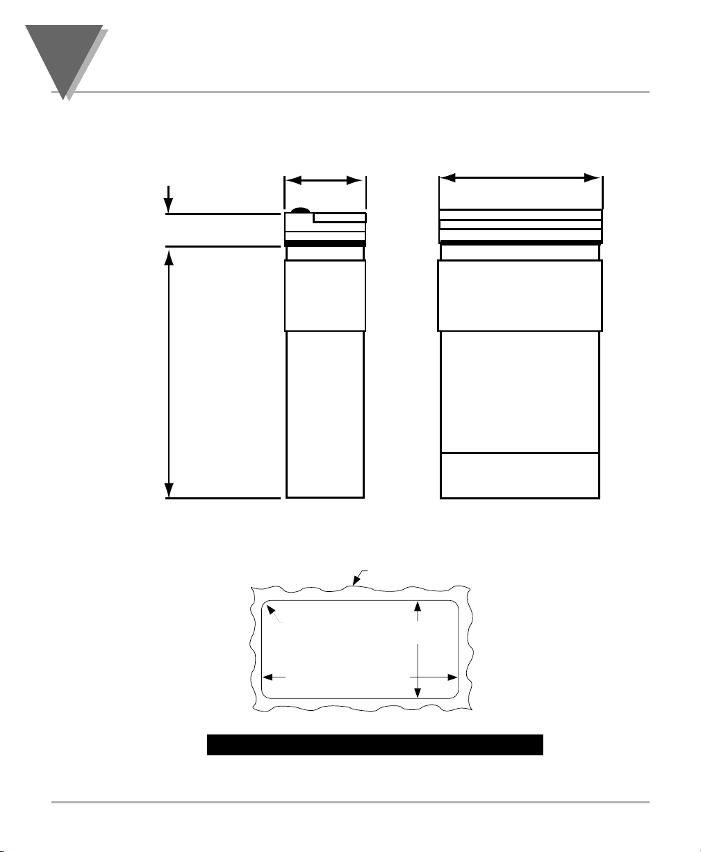
8
Specifications
56
SECTION 8. SPECIFICATIONS (Continued)
Figure 8-1 Meter Dimensions/ Panel Cutout
96,0 (3.78)48,0 (1.89)
FRONT BEZEL
20,3 (.80)
RETAINER
CASE
151,4 (5.96)
REAR COVER
SIDE VIEW
PANEL THICKNESS
6,4 (.25) MAX
0,8 (.03) MIN
1,5
R(.06)
4 PLCS
92,00 + 0,81/–0,00
(3.622 + .032/–.000)
NOTE: Dimensions in Millimeters (Inches)
45,00 + 0,61/-0,00
(1.772 + .024/–.000)
TOP VIEW
Page 67
57
Factory Preset Values
9
SECTION 9. FACTORY PRESET VALUES
Table 9-1. Factory Preset Values
MENU ITEM FACTORY PRESET VALUES
INPT Input Type: 0-20 (0-20 mA dc input)
DEC.P Decimal Point Position: FFFF
RD.S.O Reading Scale and Offset:
4-20 mA dc = 0-1000
RD.CF Reading Configuration:
R.1=T (Tare enabled)
R.2=4 (10 µV resolution for unipolar &
25 µV resolution for bipolar)
R.3=F (Filtered value)
COLR Normal Color Display:
RED or GRN (Note: depending how unit was ordered)
S1.CF Setpoint 1 Configuration:
S.1=A (Setpoint is active above)
S.2=U (Setpoint is unlatched)
S2.CF Setpoint 2 Configuration:
S.1=A (Setpoint is active above)
S.2=U (Setpoint is unlatched)
S1.DB Setpoint 1 Deadband: 0003
S2.DB Setpoint 2 Deadband: 0003
OT.CF Output Configuration:
O.1=E (Analog output is enabled)
O.2=C (Analog output is current)
O.3=A (Analog output follows the display value)
OT.S.O Output Scale and Offset:
0-1000 = 4-20 mA dc
LK.CF Lock Out Configuration
RS=E (Enable the RESET button in the Run Mode)
SP=E (Enable setpoint changes)
L3=0 (Display setpoint values)
BRIT H.BrT (Brightness Level)
SP1 Setpoint 1 Value: 0000
SP2 Setpoint 2 Value: 0000
Sensor Excitation Output: 12 Vdc
Page 68

58
CE APPROVALS INFORMATION
This product conforms to EMC 2014/30/EU (EMC directive)
Electrical Safety: 2014/35/EU (Low Voltage Directive)
Safety requirements for electrical equipment for measurement, control and laboratory.
Double Insulation
Pollution Degree 2
Dielectric withstand Test per 1 min
• Power to Input/Output:
• Power to Input/Output:
(Low Voltage dc Power Option*)
• Power to Relays Output:
• Relay 1 to Relay 2:
• Isolated Analog to Inputs:
• Analog to Inputs:
2300 Vac (3250 Vdc)
500 Vac (720 Vdc)
2300 Vac (3250 Vdc)
2300 Vac (3250 Vdc)
1000 Vac (1420 Vdc)
No Isolation
Measurement Category I
Category I are measurements performed on circuits not directly connected to the
Mains Supply (power). Maximum Line-to-Neutral working voltage is 50 Vac/dc.
This unit should not be used in Measurement Categories II, III, IV.
Transients Overvoltage Surge (1.2 / 50uS pulse)
• Input Power: 2500 V
• Input Power: 500 V
(Low Voltage dc Power Option*)
500 V• Isolated Analog:
• Input/Output Signals: 500 V
e: *Uni
Not
ts configured for external low power dc voltage, 10-32 Vdc (Basic Insulation)
**I/O signal and control lines require shielded cables and these cables
must be located on conductive cable trays or in conduits. Furthermore,
the length of these cables should not exceed 30 meters
Additional Information
RoHS II: The above product has been declared by the original supplier as
Compliant. The manufacturer of this item declares that the product complies with
the EEE RoHS II Directive 2011/65/EC.
Refer to the EMC and Safety installation considerations (Guidelines) of this manual
for additional information.
Page 69

59
NOTES60NOTES
Page 70

Page 71

WARRANTY/DISCLAIMER
OMEGA ENGINEERING, INC. warrants this unit to be free of defects in materials and workmanship for a period
of 61 months from date of purchase. OMEGA’s WARRANTY adds an additional one (1) month grace period to
the normal five (5) year product warranty to cover handling and shipping time. This ensures that OMEGA’s
customers receive maximum coverage on each product.
If the unit malfunctions, it must be returned to the factory for evaluation. OMEGA’s Customer Service
Department will issue an Authorized Return (AR) number immediately upon phone or written request. Upon
examination by OMEGA, if the unit is found to be defective, it will be repaired or replaced at no charge.
OMEGA’s WARRANTY does not apply to defects resulting from any action of the purchaser, including but
not limited to mishandling, improper interfacing, operation outside of design limits, improper repair, or
unauthorized modification. This WARRANTY is VOID if the unit shows evidence of having been tampered with
or shows evidence of having been damaged as a result of excessive corrosion; or current, heat, moisture or
vibration; improper specification; misapplication; misuse or other operating conditions outside of OMEGA’s
control. Components in which wear is not warranted, include but are not limited to contact points, fuses, and
triacs.
OMEGA is pleased to offer suggestions on the use of its various products. However, OMEGA
neither assumes responsibility for any omissions or errors nor assumes liability for any
damages that result from the use of its products in accordance with information provided by
OMEGA, either verbal or written. OMEGA warrants only that the parts manufactured by the
company will be as specified and free of defects. OMEGA MAKES NO OTHER WARRANTIES OR
REPRESENTATIONS OF ANY KIND WHATSOEVER, EXPRESSED OR IMPLIED, EXCEPT THAT OF
TITLE, AND ALL IMPLIED WARRANTIES INCLUDING ANY WARRANTY OF MERCHANTABILITY
AND FITNESS FOR A PARTICULAR PURPOSE ARE HEREBY DISCLAIMED. LIMITATION OF
LIABILITY: The remedies of purchaser set forth herein are exclusive, and the total liability
of OMEGA with respect to this order, whether based on contract, warranty, negligence,
indemnification, strict liability or otherwise, shall not exceed the purchase price of the
component upon which liability is based. In no event shall OMEGA be liable for consequential,
incidental or special damages.
CONDITIONS: Equipment sold by OMEGA is not intended to be used, nor shall it be used: (1) as a “Basic
Component” under 10 CFR 21 (NRC), used in or with any nuclear installation or activity; or (2) in medical
applications or used on humans. Should any Product(s) be used in or with any nuclear installation or activity,
medical application, used on humans, or misused in any way, OMEGA assumes no responsibility as set forth
in our basic WARRANTY / DISCLAIMER language, and, additionally, purchaser will indemnify OMEGA and hold
OMEGA harmless from any liability or damage whatsoever arising out of the use of the Product(s) in such a
manner.
Direct all warranty and repair requests/inquiries to the OMEGA Customer Service Department. BEFORE
RETURN REQUESTS/INQUIRIES
RETURNING ANY PRODUCT(S) TO OMEGA, PURCHASER MUST OBTAIN AN AUTHORIZED RETURN (AR)
NUMBER FROM OMEGA’S CUSTOMER SERVICE DEPARTMENT (IN ORDER TO AVOID PROCESSING
DELAYS). The assigned AR number should then be marked on the outside of the return package and on any
correspondence.
The purchaser is responsible for shipping charges, freight, insurance and proper packaging to prevent
breakage in transit.
FOR WARRANTY RETURNS, please have the
following information available BEFORE contacting
OMEGA:
Purchase Order number under which the product
1.
was PURCHASED,
2.
Model and serial number of the product under
warranty, and
3.
Repair instructions and/or specific problems relative
to the product.
OMEGA’s policy is to make running changes, not model changes, whenever an improvement is possible. This affords our customers the
latest in technology and engineering.
OMEGA is a trademark of OMEGA ENGINEERING, INC.
© Copyright 2018 OMEGA ENGINEERING, INC. All rights reserved. This document may not be copied, photocopied, reproduced, trans
lated, or reduced to any electronic medium or machine-readable form, in whole or in part, without the prior written consent of OMEGA
ENGINEERING, INC.
FOR NON-WARRANTY REPAIRS,
consult OMEGA
for current repair charges. Have the following
information available BEFORE contacting
OMEGA:
1.
Purchase Order number to cover the COST of
the repair,
Model and serial number of the product, and
2.
3.
Repair instructions and/or specific problems
relative to the product.
-
Page 72

Where Do I Find Everything I Need for
Process Measurement and Control?
OMEGA…Of Course!
Shop online at omega.com
TEMPERATURE
MU
Thermocouple, RTD & Thermistor Probes, Connectors, Panels & Assemblies
MU
Wire: Thermocouple, RTD & Thermistor
MU
Calibrators & Ice Point References
MU
Recorders, Controllers & Process Monitors
MU
Infrared Pyrometers
PRESSURE, STRAIN AND FORCE
MU
Transducers & Strain Gages
MU
Load Cells & Pressure Gages
MU
Displacement Transducers
MU
Instrumentation & Accessories
FLOW/LEVEL
MU
Rotameters, Gas Mass Flowmeters & Flow Computers
MU
Air Velocity Indicators
MU
Turbine/Paddlewheel Systems
MU
Totalizers & Batch Controllers
pH/CONDUCTIVITY
MU
pH Electrodes, Testers & Accessories
MU
Benchtop/Laboratory Meters
MU
Controllers, Calibrators, Simulators & Pumps
MU
Industrial pH & Conductivity Equipment
DATA ACQUISITION
MU
Communications-Based Acquisition Systems
MU
Data Logging Systems
MU
Wireless Sensors, Transmitters, & Receivers
MU
Signal Conditioners
MU
Data Acquisition Software
HEATERS
MU
Heating Cable
MU
Cartridge & Strip Heaters
MU
Immersion & Band Heaters
MU
Flexible Heaters
MU
Laboratory Heaters
ENVIRONMENTAL
MONITORING AND CONTROL
MU
Metering & Control Instrumentation
MU
Refractometers
MU
Pumps & Tubing
MU
Air, Soil & Water Monitors
MU
Industrial Water & Wastewater Treatment
MU
pH, Conductivity & Dissolved Oxygen Instruments
M3597/0918
 Loading...