

Page 1
®
®
Shop on line at
RoHS 2 Compliant
Page 2

This device is marked with the international caution symbol. It is important to read the Setup Guide before
installing or commissioning this device as it contains important information relating to safety and EMC.
®
®
OMEGAnet® On-Line Service
www.omega.com
Internet e-mail
Servicing North America:
USA: One Omega Drive, P.O. Box 4047
ISO 9001 Certified Stamford CT 06907-0047
Canada:
TEL: (203) 359-1660 FAX: (203) 359-7700
e-mail: [email protected]
976 Bergar
Laval (Quebec) H7L 5A1
TEL: (514) 856-6928 FAX: (514) 856-6886
e-mail: [email protected]
For immediate technical or application assistance:
USA and Canada: Sales Service: 1-800-826-6342 / 1-800-TC-OMEGA
Mexico and TEL: (001)800-TC-OMEGA® FAX: (001) 203-359-7807
Latin American: En Espa
Customer Service: 1-800-622-2378 / 1-800-622-BEST
Engineering Service: 1-800-872-9436 / 1-800-USA-WHEN
ñol: (001) 203-359-7803
e-mail: [email protected]
®
®
®
Servicing Europe:
Benelux: Postbus 8034, 1180 LA Amstelveen, The Netherlands
Czech Republic:
France:
Germany/Austria: Daimlerstrasse 26, D-75392 Deckenpfronn, Germany
United Kingdom:
ISO 9002 Certified River Bend Technology Centre
It is the policy of OMEGA to comply with all worldwide safety and EMC/EMI regulations that apply.
OMEGA is constantly pursuing certification of its products to the European New Approach Directives.
OMEGA will add the mark to every appropriate device upon certification.
The information contained in this
any errors it contains, and reserves the right to alter specifications without notice.
WARNING: These products are not designed for use in, and should not be used for, patient connected applications.
TEL: +31 20 3472121 FAX: +31 20 6434643
Toll Free in Benelux: 0800 0993344
e-mail: [email protected]
Frystatska 184, 733 01 Karviná
TEL: +420 59 6311899 FAX: +420 59 6311114
e-mail: [email protected]
11, rue Jacques Cartier, 78280 Guyancourt
TEL: +33 1 61 37 29 00 FAX: +33 1 30 57 54 27
Toll Free in France: 0800 466 342
e-mail: [email protected]
TEL: +49 7056 9398-0 FAX: +49 7056 9398-29
Toll Free in Germany: 0800 639 7678
e-mail: [email protected]
One Omega Drive
Northbank, Irlam Manchester M44 5BD United Kingdom
TEL: +44 161 777 6611 FAX: +44 161 777 6622
Toll Free in England: 0800 488 488
e-mail: [email protected]
document is believed to be correct but OMEGA Engineering, Inc. accepts no liability for
Page 3

Table of Contents
Section Page
1 SETUP . . . . . . . . . . . . . . . . . . . . . . . . . . . . . . . . . .1
1.1.1 Customer Service . . . . . . . . . . . . . . . . . . . . . . . . .1
1.1.2 Inspecting Your Shipment . . . . . . . . . . . . . . . . .1
1.1.3 What You Will Need . . . . . . . . . . . . . . . . . . . . . .2
1.2.1 Basic Features . . . . . . . . . . . . . . . . . . . . . . . . . . . .3
1.2.2 Options . . . . . . . . . . . . . . . . . . . . . . . . . . . . . . . . .3
1.3 Safety Considerations . . . . . . . . . . . . . . . . . . . . .4
1.4 Getting Started . . . . . . . . . . . . . . . . . . . . . . . . . . .5
1.4.1 Mount the Unit . . . . . . . . . . . . . . . . . . . . . . . . . . .5
1.4.2 Connect Sensor Input . . . . . . . . . . . . . . . . . . . . .7
1.4.3 Connect the AC Power Cord . . . . . . . . . . . . . . .8
1.4.4 Turn On the Unit . . . . . . . . . . . . . . . . . . . . . . . . .9
2 OPERATION . . . . . . . . . . . . . . . . . . . . . . . . . . .10
2.1 Introduction . . . . . . . . . . . . . . . . . . . . . . . . . . . .10
2.2 Meter Buttons . . . . . . . . . . . . . . . . . . . . . . . . . . .11
2.3 Display Descriptions . . . . . . . . . . . . . . . . . . . . .12
2.4 Menu Configurations . . . . . . . . . . . . . . . . . . . .12
3 DEFAULTS & SPECIFICATIONS . . . . . . . .21
3.1 Back of the Meter . . . . . . . . . . . . . . . . . . . . . . . .21
3.2 Main Board AC Power Jumpers . . . . . . . . . . .24
3.3 S51,-S4 Jumpers . . . . . . . . . . . . . . . . . . . . . . . . .26
3.4 Specifications . . . . . . . . . . . . . . . . . . . . . . . . . . .28
4
INFORMATION . . . . . . . . . . . . . . . . . . . .31
Page 4

List of Figures
Figure Page
1.1 Panel Cut-out Dimensions . . . . . . . . . . . . . .5
1.2 Thermocouple Input Connection . . . . . . . . .7
3.1 Connectors (ac-powered) . . . . . . . . . . . . . .21
3.2 Connectors (dc-powered) . . . . . . . . . . . . . .22
3.3 115Vac Jumpers (Default) . . . . . . . . . . . . . .25
3.4 230Vac Jumpers . . . . . . . . . . . . . . . . . . . . . . .25
3.5 S51.-S4 Jumpers . . . . . . . . . . . . . . . . . . . . . . .27
3.6 Meter Dimensions . . . . . . . . . . . . . . . . . . . .30
List of Tables
Table Page
1.1 AC Power Wire Color & Connections . . . . .8
2.1 Meter Buttons . . . . . . . . . . . . . . . . . . . . . . . .11
2.2 Display Desriptions . . . . . . . . . . . . . . . . . . .12
3.1 Connector Descriptions . . . . . . . . . . . . . . . .23
3.2 S51-S4 Jumpers . . . . . . . . . . . . . . . . . . . . . . .26
Page 5

1.1 Before You Begin
If you need assistance, please contact the
Customer Service Department nearest
you.
Remove the packing slip and verify that
you have received everything listed,
including:
1 Indicator/controller with all applicable
connectors attached
1 Owner’s Manual
If you ordered any of the available
options (except the “BL” blank Lens
option), they will be shipped in a
separate container to avoid any damage
to your indicator/controller.
1.1.2
Inspecting
Your
Shipment
1.1.1
Customer
Service
SETUP
1
1
Page 6

Inspect the container and equipment for
signs of damage as soon as you receive
the shipment. Note any evidence of
rough handling in transit. Immediately
report any damage to the shipping
agent. The carrier will not honor
damage claims unless all shipping
material is saved for inspection. After
examining and removing the contents,
save the packing material and carton in
the event reshipment is necessary.
In addition to the meter and connectors,
you will need the following items to setup
your unit:
115VAC three-prong power cord
1
/8" flat head screwdriver
1.1.3 What
You Will
Need
SETUP
1
2
Warning!
Page 7

SETUP
1
3
1.2 Features and Options
Your meter has several basic features,
some of which are listed below. For more
detailed information on specifications and
factory defaults, see Part 3: Defaults &
Specifications.
4 digit, 7 segment LED display with
programmable decimal point
Nonvolatile memory — no battery backup
necessary
115Vac or 230Vac 50/60 Hz power source
The unit is available with an optional
NEMA-4 front panel cover. Please contact
Customer Service for a list of additional
products and accessories.
1.2.2
Options
1.2.1 Basic
Features
Page 8

1.3 Safety Considerations
The unit is protected in accordance with
Class II of IEC 348 and VDE 0411.
Remember that the unit has no power-on
switch. It will be in operation as soon as
you connect it to a power source.
Do not expose the unit to rain or moisture.
Do not operate your unit in flammable or
explosive atmospheres. As with any
electronic instrument, you may encounter
high voltage exposure when installing,
calibrating, or removing parts. Be careful
when working near conductors carrying
large currents. Use twisted-pair
connections to the unit. Use magnetic
shielding materials, or move the unit away
from the current source to reduce
magnetic field problems. Do not exceed
power rating on label located on the top of
the controller housing. Failure to follow
all instructions and warnings may result
in injury!
Warning!
SETUP
1
4
Page 9
1.4 Getting Started
Follow these steps to start using your unit
right away:
Mount the unit
Connect Sensor Input
Connect the AC power cord
Turn on the unit
1. Remove the two nuts at the back of
the unit, which hold the mounting
sleeve. Remove the sleeve.
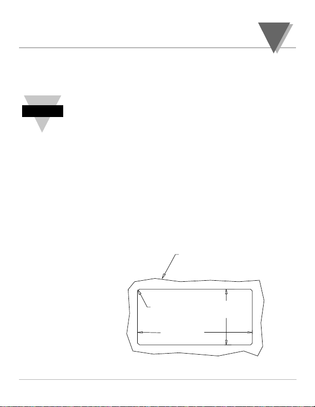
2. Cut a hole in your panel, as shown.
Figure 1.1 — Panel Cut-out Dimensions
1.4.1
Mount the
Unit
Overview
SETUP
1
5
THICKNESS:
PANEL
0.03 [0.8] MIN
0.25 [6.4] MAX
0.06
R
[1.5]
4 PLCS
3.622 +.032/-.000
[92.00 +0.81/-0.00]
1.772 +.024/-.000
[45.00 +0.61/-0.00]
Page 10
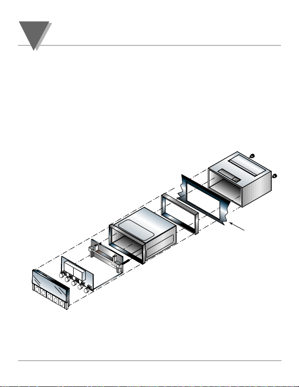
3. Insert the unit into the hole. Be sure
the front bezel is flush to your panel.
Slide on the mounting sleeve from the
rear of the panel and tighten the unit
until snug, using the two nuts.
SETUP
1
6
Panel Cutout
Page 11
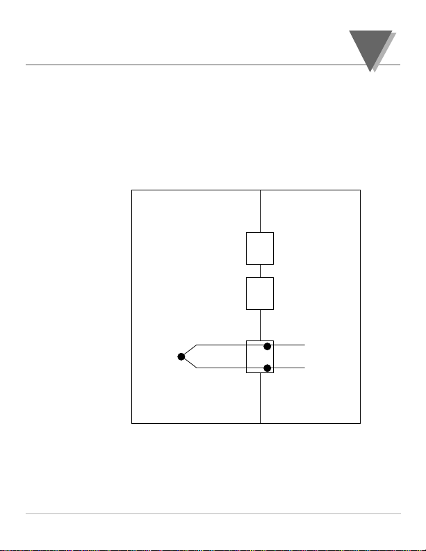
Figure 1.2 — Thermocouple Input Connection
1.4.2
Connect
Sensor
Input
SETUP
1
7
J1
J2
J4
1
2
RED
Page 12

1.
Locate the connector pins. (see Figure 3.1)
Do not connect AC power to your unit until
all input and output connections have been
properly established. Failure to do so may
result in injury.
2. Insert the correct wire in each terminal and tighten the
lockdown screw. See Table 1.1 for wire color
definitions. Tug gently on the wires to verify that the
connections are secure.
Connection Europe USA
AC-High Brown Black
AC-Low Blue White
AC -Ground Green/Yellow Green
Table 1.1 — AC Power Wire Color & Connections
1.4.3
Connect the
AC Power
Cord
SETUP
1
8
Warning!
Page 13

1. Plug the unit into a properly grounded
115V power supply. The unit will
initialize, scrolling the following three
messages on the front panel:
Idt
code
r 0I
(r 0I equals the revision code of
the micro controller. Keep track
of the revision code for future reference.)
2. The present value of the
Thermocouple should be displayed. If
a value is not displayed, follow these
steps:
Unplug the unit
Verify the power and TC connections
Check your power source
Plug the unit in again
1.4.4 Turn
On the Unit
SETUP
1
9
Page 14

2.1 Introduction
The unit has two different modes of
operation. The first, Run Mode, is used to
display process value and display or clear
peak and valley values. The other mode,
Configuration Mode, is used to navigate
through the menus options and configure
the meter.
The S51 jumper must be removed (which
is the factory setting) and the S4 jumper
must be installed (which is not the factory
setting) for all menu configuration options
to be available. (See page 34 for further
jumper information.)
This part of the manual, Operation, will
explain both the Run Mode and the
Configuration Mode and is divided into
the following sections:
Meter Buttons
Display Descriptions
Menu Configurations
0PERATION
2
10
Overview
Page 15

2.2 Meter Buttons
Button Description
RESET Reset the peak and
valley values
MENU Enter Configuration
(Menu) mode
/MIN Display the valley value
(flashing)
/MAX Display the peak value
(flashing)
C/F Toggle display between
°C and °F
Table 2.1 — Button Functions
0PERATION
2
11
Page 16

2.3 Display Descriptions
Display
Message Description
nnnn Peak value to follow
uuuu Valley value to follow
0l Open thermocouple input
rst Peak/Valley Reset
Table 2.2 — Display Descriptions
2.4 Menu Configurations
2.4.1 Selecting the Input
Thermocouple Type
The unit is designed to handle up to eight
different thermocouple types. To select the
thermocouple type, follow these steps:
1. Press the MENU button. The meter will
momentarily displays:
TYPE
TYPE
OPERATION
2
12
Page 17

2. Press the /MIN button. You may
scroll through the following choices:
Displayed as:
J j
K +
T t
E e
N n
DIN J di n j
R r
S s
2. Press the /MIN button to scroll
through available choices
3. Press the MENU button to store and
activate your selection.
2.4.2 Selecting the Decimal Point
The unit can display temperatures in 1° or
0.1° resolution. When using type R or S
the meter will only be indicating with 1°
resolution. The DEc.P menu item will not
be available for these two types of
thermocouples.
1. Press MENU until display displays:
dEc.P
dEcp
OPERATION
2
13
Page 18

2. After a moment the display will
indicate the currently selected decimal
point (resolution) configuration.
3. AUTO will be displaced if the meter is
configured to display any temperature
between -100° and 1000° with 0.1
resolution (meter will switch to 1°
resolution above and below these
temperatures automatically.)
4. 1dEg will be displayed when the
meter is configured for 1° resolution.
5. Pressing the /MIN button allows you
to toggle between these choices:
AUTO (0.1°/1°)
1dEg (1°) resolution
6. Press the MENU button to save and
activate your selection.
OPERATION
2
14
Page 19

2.4.3 Meter Cold-Junction Offset
Calibration procedure
This menu item will allow you to adjust the
cold junction offset calibration.
1. Press MENU until meter flashes:
C.J. Z (cold junction zero)
2. Connect the proper thermocouple to
the input at J4 and using a
thermocouple calibrator apply 0.0°C.
3. Press /MAX to display the cold-
junction offset. (If the meter reading at
this point is more than 5.0 recheck your
Thermocouple connections and make
sure 0.0°C is applied.)
4. The Cold-junction calibration on the
unit is semi-automatic. Press MENU to
activate the internal compensation. The
display will begin to flash and
automatically adjust the offset reading
on the display to 0.0 (± 0.1)
OPERATION
2
15
Page 20

This automatic cold junction calibration
should be all that is necessary to calibrate
the CJ offset, however if you want to
additionally adjust the offset manually, the
/MAX and /MIN buttons at this point
can be used to manually increase (/MAX)
or decrease (/MIN) the display 0.1° each
time /MAX or /MIN is pressed. After
each press allow several seconds to let the
display stabilize. Press MENU to save and
activate the calibration. (Meter will briefly
display Stor.)
The following menu items will only be
available with S4 installed.
CNFG CF=0 DEFAULT
CNFG cf=1,2 Functions not available
LINE 50H 60H 60H DEFAULT
CAL = For use only by qualified
personnel with accurate calibration
equipment.
OPERATION
2
16
Page 21

2.4.4 Line Frequency Selection
This item will only be available if the S4
jumper, which enables the calibration
configuration, is installed!
This menu item will allow you to select the
local line frequency used by the meter.
1. Press MENU until display displays:
LI N E
2. After a moment the display will
indicate the currently selected line
frequency.
3. Pressing the /MIN button allows you
to toggle between these choices:
50 H (50 Hz)
60 H (60 Hz)
4. Press the MENU button to save and
activate your selection.
LINE
OPERATION
2
17
Page 22

2.4.5 Calibration Menu
Caution: It is not necessary to calibrate a
brand new meter, it arrives completely
calibrated. Accessing the calibration
menu will affect the meter’s calibration
and should only be performed by
qualified personnel with accurate test
equipment.
2.4.5.1 Meter SPAN calibration
procedure
This item will only be available if the S4
jumper, which enables the calibration
configuration, is installed!
The Span calibration does not require any
special compensated thermocouple wires at
the input terminals. Standard copper wire
hooked up to a mV calibration source is
required.
CAL
OPERATION
2
18
Page 23

This menu item will allow you to adjust the
SPAN calibration used by the meter.
1. Press MENU until meter flashes:
CAL
2. Press /MIN button. Meter will now
display:
SP.C (Span Calibration)
3. Press /MAX button. Meter will
display:
0IN
4. Apply 0 mV to input terminals 1 and 2
of J4. Let meter stabilize for 10 seconds
then press MIN to accept. Meter will
display:
75IN
OPERATION
2
19
Page 24

5. Apply 75 mV to input terminals at J4.
Let meter stabilize for 10 seconds then
press MIN to accept. Meter will
display:
0IN (40 mV zero reading)
6. Apply 0 mV to input terminals at J4.
Let meter stabilize for 10 seconds then
press MIN to accept. Meter will
display:
40IN
7. Apply 40 mV to input terminals at J4.
Let meter stabilize for 10 seconds then
press MIN to accept.
8. Meter will briefly display rST
indicating the span calibration is saved
in non-volatile memory.
OPERATION
2
20
Page 25
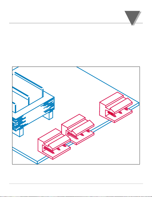
3.1 Back of the Meter
Figures 3.1 and 3.2 show the connectors on the back of the meter
for ac and dc models respectively. Table 3.1 gives a brief
description of each connector at the back of the meter.
Figure 3.1 — Connectors (ac-powered)
AC HI
AC LO
AC GND
1
2
3
1
2
3
1
2
3
T1
MAIN BOARD
J1
J2
J4
DEFAULTS
& SPECIFICATIONS
3
21
Page 26
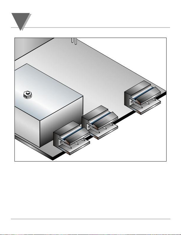
Figure 3.2 — Connectors (dc-powered)
J1
J2
J4
MAIN BOARD
+ INPUT
- INPUT
T2
C3C, 9-32VDC
10403A2-01
1
2
3
1
2
3
1
2
3
DEFAULTS & SPECIFICATIONS
3
22
Page 27

Connector Description
J1-1 AC high connection (NC on DC-powered units)
J1-2 AC low connection (+ input on DC-powered
units)
J1-3 AC ground (DC-power return on DC-powered
units)
J2-1 Display hold input (active low) — connect to J2-2
to hold meter reading.
PPeeaakk aanndd vvaalllleeyy
rreeaaddiinnggss aarree ccoonnttiinnuuoouussllyy uuppddaatteedd dduurriinngg
ddiissppllaayy hhoolldd eevveenn tthhoouugghh ddiissppllaayy iiss oonn hhoolldd..
J2-2 Ground
J2-3 Display blank input (active low) — connect to
J2-2 to blank meter display.
J4-1 + TC input
J4-2 - TC input (red wire)
Table 3.1— Connector Descriptions
DEFAULTS
& SPECIFICATIONS
3
23
Page 28

3.2 Main Board AC Power Jumpers
To check voltage jumpers, or to change from 115 V to 230 Vac:
1. Disconnect the AC power from the meter.
2. Remove the front lens, if present.
3. Pull the meter forward, out of its case.
DEFAULTS & SPECIFICATIONS
3
24
Page 29
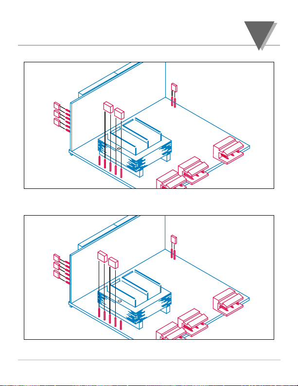
Figure 3.3 — 115Vac Jumpers (Default)
Figure 3.4 — 230Vac Jumpers
J1
J2
J4
W1
W3
W2
W4
S4
JUMPER
FOR
230VAC
DISPLAY
S3
S2
S1
MAIN BOARD
1
2
3
T1
1
2
3
W1
W3
W2
W4
JUMPER
FOR
115VAC
1
2
3
1
2
3
T1
S4
MAIN BOARD
DISPLAY
S3
S2
S1
J1
J2
J4
DEFAULTS
& SPECIFICATIONS
3
25
Page 30

3.3 S51, S4 Jumpers
The S51 Jumpers is at the front of the meter near the digital
display. The S4 Jumpers is on the side of the main board (see
Figure 3.5). (Defaults are in bold and italic.)
1. Disconnect the main power from the meter.
2. Remove the front lens, if present.
3. Pull the meter forward, out of its case.
Jumper Description
S51 installed: front panel buttons locked out
removed: all buttons operable.
Jumper placed in storage
position on one PIN only.
S4 installed: calibration enabled
removed: calibration disabled.
Jumper placed in storage
position on one PIN only.
Table 3.2 — S51–S4 Jumpers
DEFAULTS & SPECIFICATIONS
3
26
Page 31
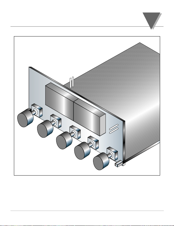
Figure 3.5 — S51,–S4 Jumpers
S4
S51
DEFAULTS
& SPECIFICATIONS
3
27
Page 32

3.4 Specifications
3.4.1 General Specifications
Microprocessor based
Input type: Type J, DINJ, K, T, E, N, R, S
Max Error: ± 1 deg C (± 1.8 °F)
Accuracy at 25°C: ± .5 deg C (± .8°C for DINJ)
Cold-junction
compensation tempco 0.07°C/°C
3.4.2 Display
type: 7 segments
red or green
4 digit
height: 0.56in (14.2mm)
3.4.3 Thermocouple Types
Range
Type Deg C DegF
J -210 -346
760 1400
DIN J -200 -328
900 1652
KK ((ffaaccttoorryy ddeeffaauulltt))
-270 -454
1372 2500
T -270 -454
400 752
E -270 -454
1000 1832
R/S -50 -58
1768 3214
N -270 -454
1300 2372
DEFAULTS & SPECIFICATIONS
3
28
Page 33

3.4.4 Resolution
0.1° or 1° resolution
dEc.P = AUTO
((ffaaccttoorryy ddeeffaauulltt))
1° resolution dEc.P = 1dEg
3.4.5 Power
115 or 230 Vac
±15% (2 Watt max.)
frequency: 50Hz or
6600HHzz ((ffaaccttoorryy ddeeffaauulltt))
Isolation: 354V peak per IEC spacing
NMR 60dB
CMR 120 dB
DC voltage: 10–32Vdc isolated to 300Vp
3.4.6 Environmental
Operating temp: 0–60°C
Storage temp: -40 to +85°C
Relative humidity: 95% at 40°C (non condensing)
3.4.7 Case
DIN 4896-100
Panel cutout: 1.77 X 3.62 in (45 X 92mm)
Depth behind bezel: 3.94 in (100mm)
material: 94V-0 UL-rated polycarbonate
DEFAULTS
& SPECIFICATIONS
3
29
Page 34
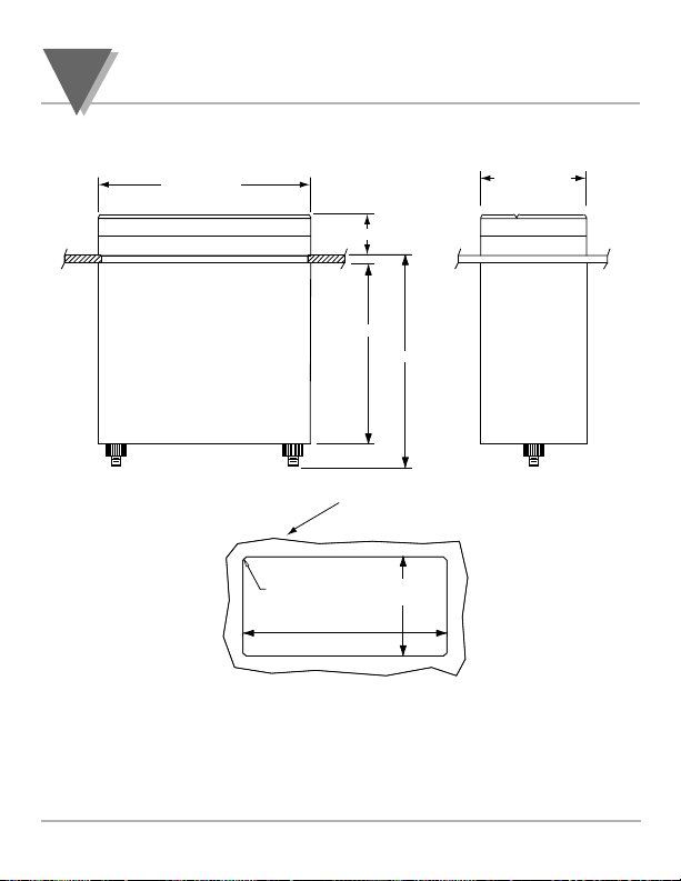
3.4.8 Meter Dimensions
Figure 3.6 — Meter Dimensions
DEFAULTS & SPECIFICATIONS
3
30
96.00 (3.780)
0.73 (18.67)
3.22 (81.7)
3.74 (95.0)
MAX
48.00(1.890)
TOP VIEW
PANEL THICKNESS:
6,4 (.25) MAX
0,8 (.03) MIN
1,5
R
4 PLCS
45,01 +0,61/-0,00
(.06)
(1.772 +.024/-.000)
92,00 +0,81/-0,00
(3.622 +.032/-.000)
SIDE VIEW
PANEL CUTOUT
Page 35

INFORMATION
31
This product conforms to the EMC directive 89/336/EEC amended by
93/68/EEC, and with the European Low Voltage Directive 72/23/EEC.
Electrical Safety EN61010-1:2001
Safety requirements for electrical equipment for measurement, control
and laboratory.
• Double Insulation: Primary to Secondaries
• Pollution Degree 2
• Measurement *Category I
Note 1: *Measurements performed on circuits not directly connected
to the Mains Supply (power). Maximum Line-to-Neutral working
voltage 50Vac/dc.
Note 2: This unit should not be used in Measurement Categories II, III, IV.
• Dielectric withstand Test per 1 min (50/60Hz)
Power to Input/Output 2500Vac
• Transients Overvoltage
Input Power Transients Overvoltage 2500V
Input/Output Signals Transients Overvoltage 500V
EMC EN61326:1997 + and A1: 1998 + A2: 2001
Immunity and Emissions requirements for electrical equipment for
measurement, control and laboratory.
• EMC Emissions Class B, EN61326
• EMC Immunity** Table 1, EN61326
** I/O Signal and Control Lines require shielded cables and these cables
must be located on conductive cable trays or in conduits. Furthermore,
the length of these cables should not exceed 30 meters.
Refer to the EMC and Safety installation considerations (Guidelines)
of this manual for additional information.
4
Page 36

WARRANTY/DISCLAIMER
OMEGA ENGINEERING, INC. warrants this unit to be free of defects in materials and workmanship for a
period of 13 months from date of purchase. OMEGA Warranty adds an additional one (1) month grace
period to the normal one (1) year product warranty to cover handling and shipping time. This
ensures that OMEGA’s customers receive maximum coverage on each product.
If the unit should malfunction, it must be returned to the factory for evaluation. OMEGA’s Customer Service
Department will issue an Authorized Return (AR) number immediately upon phone or written request.
Upon examination by OMEGA, if the unit is found to be defective it will be repaired or replaced at no
charge. OMEGA’s WARRANTY does not apply to defects resulting from any action of the purchaser, including but not limited to mishandling, improper interfacing, operation outside of design limits,
improper repair, or unauthorized modification. This WARRANTY is VOID if the unit shows evidence of
having been tampered with or shows evidence of being damaged as a result of excessive corrosion; or current, heat, moisture or vibration; improper specification; misapplication; misuse or other operating conditions outside of OMEGA’s control. Components which wear are not warranted, including but not
limited to contact points, fuses, and triacs.
OMEGA is pleased to offer suggestions on the use of its various products. However,
OMEGA neither assumes responsibility for any omissions or errors nor assumes liability for any
damages that result from the use of its products in accordance with information provided by
OMEGA, either verbal or written. OMEGA warrants only that the parts manufactured by it will be
as specified and free of defects. OMEGA MAKES NO OTHER WARRANTIES OR
REPRESENTATIONS OF ANY KIND WHATSOEVER, EXPRESSED OR IMPLIED, EXCEPT THAT OF
TITLE, AND ALL IMPLIED WARRANTIES INCLUDING ANY WARRANTY OF MERCHANTABILITY AND
FITNESS FOR A PARTICULAR PURPOSE ARE HEREBY DISCLAIMED. LIMITATION OF
LIABILITY: The remedies of purchaser set forth herein are exclusive and the total liability of
OMEGA with respect to this order, whether based on contract, warranty, negligence,
indemnification, strict liability or otherwise, shall not exceed the purchase price of the
component upon which liability is based. In no event shall OMEGA be liable for
consequential, incidental or special damages.
CONDITIONS: Equipment sold by OMEGA is not intended to be used, nor shall it be used: (1) as a “Basic
Component” under 10 CFR 21 (NRC), used in or with any nuclear installation or activity; or (2) in medical
applications or used on humans. Should any Product(s) be used in or with any nuclear installation or
activity, medical application, used on humans, or misused in any way, OMEGAassumes no responsibility
as set forth in our basic WARRANTY/ DISCLAIMER language, and additionally, purchaser will indemnify
OMEGA and hold OMEGA harmless from any liability or damage whatsoever arising out of the use of the
Product(s) in such a manner.
RETURN REQUESTS / INQUIRIES
Direct all warranty and repair requests/inquiries to the OMEGA Customer Service Department. BEFORE
RETURNING ANY PRODUCT(S) TO OMEGA, PURCHASER MUST OBTAIN AN AUTHORIZED RETURN
(AR) NUMBER FROM OMEGA’S CUSTOMER SERVICE DEPARTMENT (IN ORDER TO AVOID
PROCESSING DELAYS). The assigned AR number should then be marked on the outside of the return
package and on any correspondence.
The purchaser is responsible for shipping charges, freight, insurance and proper packaging to prevent
breakage in transit.
FOR W
ARRANTY RETURNS, please have the
following information available BEFORE
contacting OMEGA:
1. P.O. number under which the product was
PURCHASED,
2. Model and serial number of the product under
warranty, and
3. Repair instructions and/or specific problems
relative to the product.
FOR NON-WARRANTY REPAIRS,
consult OMEGA
for current repair charges. Have the following
information available BEFORE contacting OMEGA:
1. P.O. number to cover the COST
of the repair,
2. Model and serial number of product, and
3. Repair instructions and/or specific problems
relative to the product.
USA
MADE
IN
OMEGA’s policy is to make running changes, not model changes, whenever an improvement is possible. This affords our
customers the latest in technology and engineering.
OMEGA is a registered trademark of OMEGA ENGINEERING, INC.
© Copyright 2004 OMEGA ENGINEERING, INC. All rights reserved. This document may not be copied, photocopied, repro-
duced, translated, or reduced to any electronic medium or machine-readable form, in whole or in part, without prior written consent of OMEGA ENGINEERING, INC.
PATENT NOTICE: PATENT NOTICE: The “Meter Case Bezel Design” is a trademark of NEWPORT Electronics, Inc.,
registered in the U.S. USED UNDER LICENSE. This product is covered by one or more of the following patents: U.S. Pat.
No. Des. 336,895; 5,274,577 / CANADA 2052599; 2052600 / ITALY 1249456; 1250938 / FRANCE BREVET No. 91 12756 /
SPAIN 2039150; 2048066 / UK PATENT No. GB2 249 837; GB2 248 954 / GERMANY DE 41 34398 C2. OTHER
INTERNATIONAL PATENTS PENDING.
Page 37

M2342/0504
Where Do I Find Everything I Need for
Process Measurement and Control?
OMEGA…Of Course!
Shop on line at www.omega.com
TEMPERATURE
Thermocouple, RTD & Thermistor Probes, Connectors, Panels & Assemblies
Wire: Thermocouple, RTD & Thermistor
Calibrators & Ice Point References
Recorders, Controllers & Process Monitors
Infrared Pyrometers
PRESSURE, STRAIN AND FORCE
Transducers & Strain Gauges
Load Cells & Pressure Gauges
Displacement Transducers
Instrumentation & Accessories
FLOW/LEVEL
Rotameters, Gas Mass Flowmeters & Flow Computers
Air Velocity Indicators
Turbine/Paddlewheel Systems
Totalizers & Batch Controllers
pH/CONDUCTIVITY
pH Electrodes, Testers & Accessories
Benchtop/Laboratory Meters
Controllers, Calibrators, Simulators & Pumps
Industrial pH & Conductivity Equipment
DATA ACQUISITION
Data Acquisition & Engineering Software
Communications-Based Acquisition Systems
Plug-in Cards for Apple, IBM & Compatibles
Datalogging Systems
Recorders, Printers & Plotters
HEATERS
Heating Cable
Cartridge & Strip Heaters
Immersion & Band Heaters
Flexible Heaters
Laboratory Heaters
ENVIRONMENTAL
MONITORING AND CONTROL
Metering & Control Instrumentation
Refractometers
Pumps & Tubing
Air, Soil & Water Monitors
Industrial Water & Wastewater Treatment
pH, Conductivity & Dissolved Oxygen Instruments
 Loading...