

Page 1
User’s Guide
®
An OMEGA Technologies Company
www.omega.com
e-mail:[email protected]
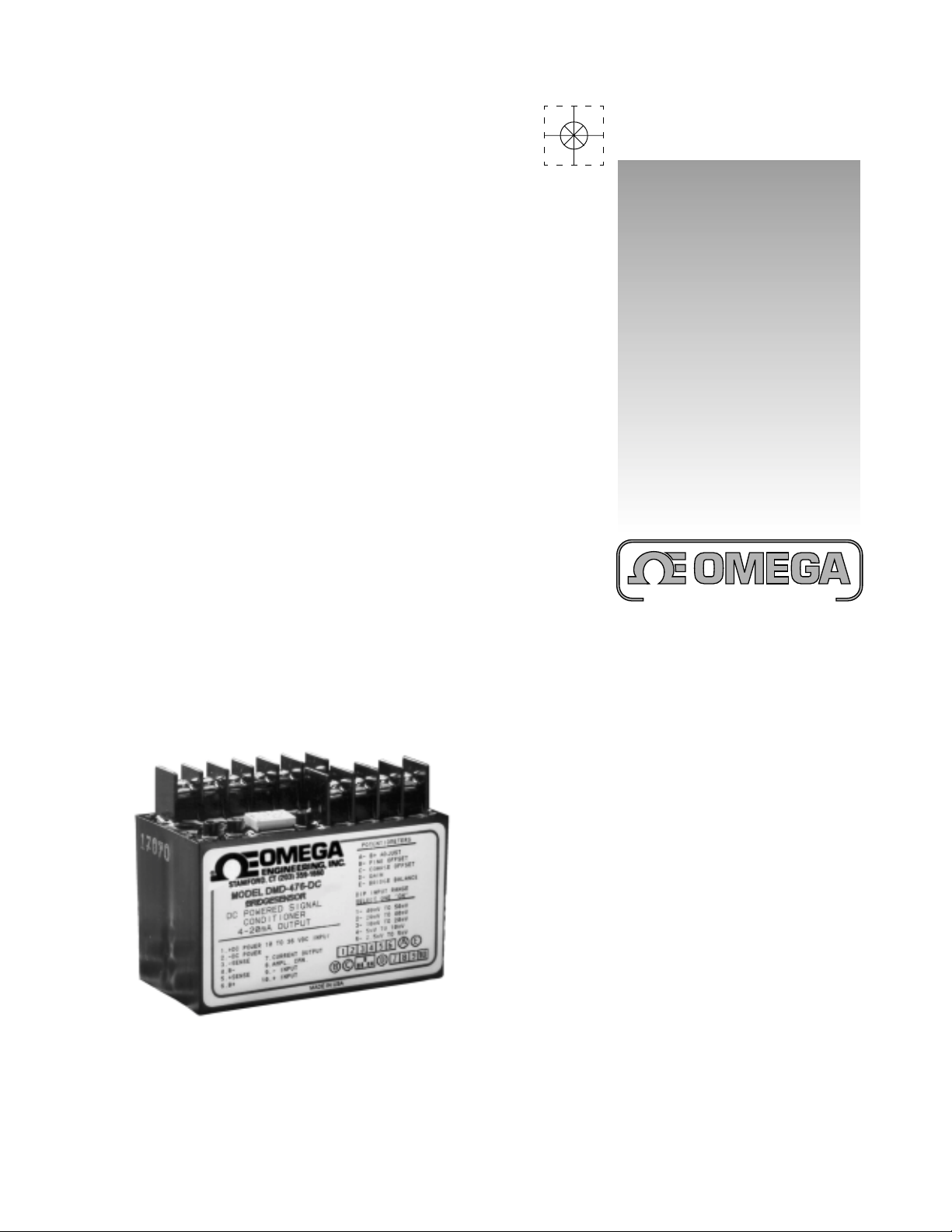
DMD-476-DC Bridgesensor
DC Powered Signal Conditioner
Page 2

®
Internet e-mailInternet e-mail
Internet e-mail
Internet e-mailInternet e-mail
OMEGAnetOMEGAnet
OMEGAnet
OMEGAnetOMEGAnet
http://wwwhttp://www
http://www
http://wwwhttp://www
omega.com
®®
®
®®
On-Line Service On-Line Service
On-Line Service
On-Line Service On-Line Service
.omega.com.omega.com
.omega.com
.omega.com.omega.com
®
Servicing North America:
USA:USA:
USA:
USA:USA:
ISO 9001 Certified Stamford, CT 06907-0047
Canada:Canada:
Canada:
Canada:Canada:
One Omega Drive, Box 4047
Tel: (203) 359-1660 FAX: (203) 359-7700
e-mail: [email protected]
976 Bergar
Laval (Quebec) H7L 5A1
Tel: (514) 856-6928 FAX: (514) 856-6886
e-mail: [email protected]
For immediate technical or application assistance:
USA and Canada:USA and Canada:
USA and Canada: Sales Service: 1-800-826-6342 / 1-800-TC-OMEGASM
USA and Canada:USA and Canada:
Customer Service: 1-800-622-2378 / 1-800-622-BESTSM
Engineering Service: 1-800-872-9436 / 1-800-USA-WHENSM
TELEX: 996404 EASYLINK: 62968934 CABLE: OMEGA
Mexico andMexico and
Mexico and
Mexico andMexico and
Latin America:Latin America:
Latin America: Tel: (95) 800-826-6342 FAX: (95) 203-359-7807
Latin America:Latin America:
En Español: (95) 203-359-7803 e-mail: [email protected]
Servicing Europe:
Benelux:Benelux:
Benelux: Postbus 8034, 1180 LA Amstelveen, The Netherlands
Benelux:Benelux:
Tel: (31) 20 6418405 FAX: (31) 20 6434643
Toll Free in Benelux: 0800 0993344
e-mail: [email protected]
Czech Republic:Czech Republic:
Czech Republic: ul. Rude armady 1868, 733 01 Karvina-Hranice
Czech Republic:Czech Republic:
Tel: 420 (69) 6311899 FAX: 420 (69) 6311114
Toll Free: 0800-1-66342
e-mail: [email protected]
France:France:
France: 9, rue Denis Papin, 78190 Trappes
France:France:
Tel: (33) 130-621-400 FAX: (33) 130-699-120
Toll Free in France: 0800-4-06342
e-mail: [email protected]
Germany/Austria:Germany/Austria:
Germany/Austria: Daimlerstrasse 26, D-75392 Deckenpfronn, Germany
Germany/Austria:Germany/Austria:
Tel: 49 (07056) 3017 FAX: 49 (07056) 8540
Toll Free in Germany: 0130 11 21 66
e-mail: [email protected]
United Kingdom:United Kingdom:
United Kingdom: One Omega Drive, River Bend T echnology Centr e
United Kingdom:United Kingdom:
ISO 9002 Certified Northbank, Irlam, Manchester
M44 5EX, England
Tel: 44 (161) 777-6611 FAX: 44 (161) 777-6622
Toll Free in the United Kingdom: 0800-488-488
e-mail: [email protected]
It is the policy of OMEGA to comply with all worldwide safety and EMC/EMI regulations that apply.
OMEGA is constantly pursuing certification of its products to the European New Approach Directives.
OMEGA will add the CE mark to every appropriate device upon certification.
The information contained in this document is believed to be correct, but OMEGA Engineering, Inc. accepts
no liability for any errors it contains, and reserves the right to alter specifications without notice.
WW
ARNINGARNING
W
ARNING: These products are not designed for use in, and should not be used for, patient-connected applications.
WW
ARNINGARNING
2
Page 3
Features
!
Complete Strain Gage Bridge Signal Conditioner
!
4-20 mA or 0-20 mA Output
!
Output Capable of Driving 1000 ohm Loop
!
Bridge Balance with 68% Tare Offset Capability
!
High Gain Amplifier; Can Accept Live Load Signals
as Low as 3 mV and Provide 16 mA Output Span
!
Sufficient Excitation Current for Five Load Cells
!
Powered by 10 to 36 VDC Unregulated
!
Rugged Epoxy Encapsulated Design
Applications
!
Weighing with Load Cells
!
Process Control Add-on Loops
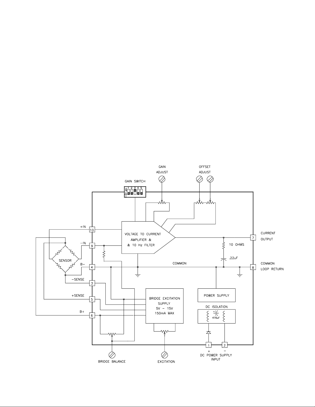
DMD-476-DC Block Diagram
Description
The Model DMD-476-DC is a self contained, DC powered
signal conditioner for bridge type instrumentation. It contains
a precision differential amplifier with filtered output and a
highlyregulated,lownoise,adjustableoutputbridgeexcitation
source. WhatsetstheDMD-476-DCapart isaBridgeBalance
pot and high gain capability to accurately condition load cell
weighing systems with large tare offsets and small live load
signals. Theunit iscompletelyencapsulated forusein rugged
environments.
3
Page 4

Specifications
napStnerruCtuptuO
napSAm61roftupnI
tsujdAoreZ
tneiciffeoCerutarepmeT
C°55ot°0
siseretsyHmumixampmaorcim05
reifilpmA
ytivitisneSlleC
)noitaticxEstloV01(
ytiraeniLlacipyt%500.0
ytilibatSerutarepmeTC°/mpp05
siseretsyHmumixamnapsfo%1.0
tnerruCsaiBtupnImumixamAp051
zH01otCD:esioNtupnImumixamP-Pstlovorcim4
tupnIedoMnommoCstloV5.7+ot0
noitcejeRedoMnommoC
zH06otCD
tuptuO
tnerruCAm02ot0
ecnatsiseRpooLmho0001ot0
ecnailpmoCmumixamstloV02
esnopseRycneuqerFretliFeloP2,ztreH01
%1.0otemiTesnopseRlacipytsm09
ylppuSnoitaticxEegdirB
egnaRtnemtsujdAstloV51ot5
tnerruCdaoLmumixamAm051
ytilibatSmumixamC°/mpp001
siseretsyH%1.0
lleCdaoLmho053htiW
ytivitisneSV/Vm3
stnemeriuqeRrewoP
egatloVtupnICDstloV63ot01
tnerruCtupnI
daol+BAm051htiw
egdirBmho053enohtiw
dewollaelppiRztreH021
ylppustupnino
noitalosIFm3300.&CDstloV007
NOTE: Specifications apply 0°Cto55°C and 10 to 36 Volts DC input.
Am21
)thgieWeraT(-tsujdAecnalaBegdirB
.detcetorpytiralopesreversi
Am02ot0;Am02ot4
Vm26otVm3
lacipytC°/pmaorcim1
muimixamC°/pmaorcim4
V/Vm2.6otV/Vm3.0
muminimBd09
elacSlluFfo%86±
dnareifilpmaehtmorfdetalosiCDsiylppusrewoptupnI
V01@A7.0otV63@A71.0
V01@A53.0otV63@A1.0
tupnistloV01taP-PtloV1
tupnistloV21evobastloV2
Getting Started with the Model DMD-476-DC
Thisprocedureis forlargetare weights,i.e.greater thanabout
10% of the cell’s full scale rating.
I. Hook Up Procedure
A. Connect the + out of your load cell to the + INPUT,
pin 10.
B. Connect the - out of your load cell to the - INPUT,
pin 9.
Note: If the ±SENSE are not used in your application, the
connections in stepC&Dneed to be followed. If the
±SENSEare goingto beused, donotjumper themas
described in stepsC&D.
C. Connect+Excitation, pin 6, to the + excitation of your
loadcellandjumperthe+SENSE,pin5,to+Excitation,
pin 6.
D. Connect -Excitation, pin 4, to the -excitation of your
loadcellandjumperthe -SENSE,pin3,to -Excitation,
pin 4.
E. Determine thevoltage of the power supplyto be used
and adjust within the 10 to 36 volt range if necessary
before connecting to the power pins, 1 and 2.
F. Verify that the hook up procedure is complete.
G. Turn on the power supply and check the bridge
excitation supply.
II. Calibration Procedure
A. Set the GAIN SWITCH position 1 ON and all others
OFF.
B. Shortthesignalinputpins 9and10together withaclip
lead. Adjust theCOARSE and FINEOFFSET pots,C
and B, for zero or 4 mA output current.
Note: Some PLC models do not accept negative inputs.
The maximum negative current is 1 mA.
C. Remove the short between the signal input pins, 9
and10. Adjustthe BRIDGE BALANCEpot forzero or
4 mA output current.
D. Set the GAIN SWITCH to the expected load cell
output.
E. Adjust the BRIDGE BALANCE pot for zero or 4 mA
output current.
F. Applythe live loadto the celland adjust theGAIN, pot
D, for the desired output current.
G. Remove live load and use the COARSE and FINE
OFFSET pots to set the zero or 4 mA output current.
H. Repeat steps E. to G. until the desired settings are
obtained.
4
Page 5
Amplifier
stnemngissApirtSlanimreT
wercS
lanimreT
noitcnuF
wercS
lanimreT
noitcnuF
1REWOPCD+6NOITICXE+
2REWOPCD-7
TNERRUC
TUPTUO
3ESNES-8 NMCREIFILPMA
4NOITATICXE-9TUPNI5ESNES+01TUPNI+
The built-in amplifier is a true differential input, low noise, low
drift, instrumentation amplifier. It has a high common mode
rejection ratio (CMRR) and is provided with an output offset
thatis potentiometeradjustable. Theoutput offsetpots adjust
theoutputzero currentup to12mA. Thezerocurrent canalso
be adjusted for 0 to 20 mA output. The instrumentation
amplifier has a gain DIP switch which changes the gain by
factors of two and a gain potentiometer for fine adjustments.
The amplifier accepts input signals of 3 mV to 62 mV. The
amplifier can withstand input voltages up to 15 Volts without
damage. The outputofthe amplifieris filteredto be3dB down
at10 Hz using a double pole Butterworth filter tominimize the
effects of high frequency electrical and physical noise on the
system.
The Model DMD-476-DC has a Bridge Balance pot which is
connected internally to the amplifier - INPUT.
MODEL 437 POWER INPUT
1000
900
800
700
600
500
400
300
SUPPLY CURRENT - mA
200
B+ LOAD = 30mA
100
0
8 1216202428323640
B+ LOAD = 150mA
POWER SUPPLY VOLTAGE
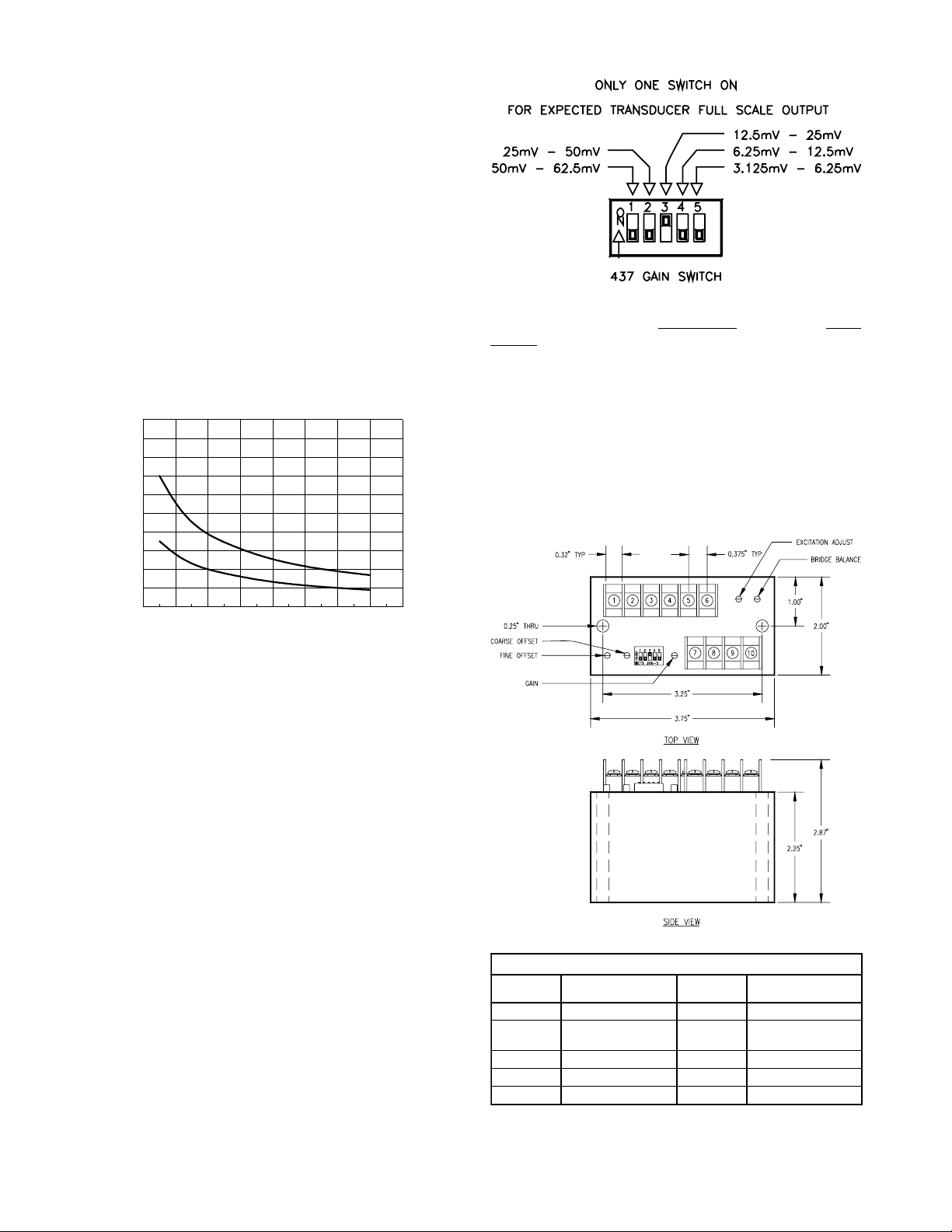
Model DMD-476-DC Gain Switch
Bridge Output Signal for:
0 to 20 mA 4 to
20 mA
Gain Switch
Position “ON”:
1 50mV to 62.5mV 40mV to 50mV
2 25mV to 50 mV 20mV to 40mV
3 12.5mV to 25mV 10mV to 20mV
4 6.25mV to 12.5mV 5mV to 10mV
5 3.125mV to 6.25mV 2.5mV to 5mV
Mechanical Specifications
Transducer Excitation
Transducer excitation is provided by an adjustable, well
regulated, low noise power supply. The excitation voltage is
adjustable by means of a molded-in potentiometer which
allows the output voltage to be varied from 5 to 15 Volts. It is
capableof supplying upto 150mA toeasily drivefive 350ohm
load cells at 10 Volts.
The +Excitation supply has remote sensing provisions for 6
wire configurations. The sense lines minimize variations in
outputvoltagewith changesin loadcurrentor leadresistance.
The supply output, +Excitation, may be connected through a
300 ohm safety barrier and the sense lines will regulate the
voltage across a 350 ohm bridge between 5 and 8 volts.
The supply has short circuit protection to protect it against
short term faults. The output recovers automatically from
short circuit conditions once the short is removed.
Bridge Balance
The Bridge Balance pot provides up to 68% of full scale tare
weight adjustment when using a 350 ohm, 3 mV/V load cell.
The DMD-476-DC can then be adjusted to provide full span
output with only about 10% of the cell’s range.
5
Page 6

(Blank)
6
Page 7

WARRANTY/DISCLAIMER
OMEGA ENGINEERING, INC. warrants this unit to be free of defects in materials and workmanship for a period
of 13 months from date of purchase. OMEGA Warranty adds an additional one (1) month grace period to the
normal one (1) year product warranty to cover handling and shipping time. This ensures that OMEGA’s
customers receive maximum coverage on each product.
If the unit malfunctions, it must be returned to the factory for evaluation. OMEGA’s Customer Service Department
will issue an Authorized Return (AR) number immediately upon phone or written request. Upon examination by
OMEGA, if the unit is found to be defective, it will be repaired or replaced at no charge. OMEGA’s WARRANTY
does not apply to defects resulting from any action of the purchaser, including but not limited to mishandling,
improper interfacing, operation outside of design limits, improper repair, or unauthorized modification. This
WARRANTY is VOID if the unit shows evidence of having been tampered with or shows evidence of having
been damaged as a result of excessive corrosion; or current, heat, moisture or vibration; improper specification;
misapplication; misuse or other operating conditions outside of OMEGA’s control. Components which wear
are not warranted, including but not limited to contact points, fuses, and triacs.
OMEGA is pleased to offer suggestions on the use of its various products. However, OMEGA neither assumes
responsibility for any omissions or errors nor assumes liability for any damages that result from the use of its
products in accordance with information provided by OMEGA, either verbal or written. OMEGA warrants only
that the parts manufactured by it will be as specified and free of defects. OMEGA MAKES NO OTHER
WARRANTIES OR REPRESENTATIONS OF ANY KIND WHATSOEVER, EXPRESS OR IMPLIED, EXCEPT THAT
OF TITLE, AND ALL IMPLIED WARRANTIES INCLUDING ANY WARRANTY OF MERCHANTABILITY AND
FITNESS FOR A PARTICULAR PURPOSE ARE HEREBY DISCLAIMED. LIMITATION OF LIABILITY: The remedies
of purchaser set forth herein are exclusive, and the total liability of OMEGA with respect to this order, whether
based on contract, warranty, negligence, indemnification, strict liability or otherwise, shall not exceed the
purchase price of the component upon which liability is based. In no event shall OMEGA be liable for
consequential, incidental or special damages.
CONDITIONS: Equipment sold by OMEGA is not intended to be used, nor shall it be used: (1) as a “Basic
Component” under 10 CFR 21 (NRC), used in or with any nuclear installation or activity; or (2) in medical
applications or used on humans. Should any Product(s) be used in or with any nuclear installation or activity,
medical application, used on humans, or misused in any way, OMEGA assumes no responsibility as set forth
in our basic WARRANTY / DISCLAIMER language, and, additionally, purchaser will indemnify OMEGA and
hold OMEGA harmless from any liability or damage whatsoever arising out of the use of the Product(s) in such
a manner.
RETURN REQUESTS/INQUIRIES
Direct all warranty and repair requests/inquiries to the OMEGA Customer Service Department. BEFORE
RETURNING ANY PRODUCT(S) TO OMEGA, PURCHASER MUST OBTAIN AN AUTHORIZED RETURN (AR)
NUMBER FROM OMEGA’S CUSTOMER SERVICE DEPARTMENT (IN ORDER TO AVOID PROCESSING DELAYS).
The assigned AR number should then be marked on the outside of the return package and on any correspondence.
The purchaser is responsible for shipping charges, freight, insurance and proper packaging to prevent breakage
in transit.
FOR WARRANTY RETURNS, please have the
following information available BEFORE contacting
OMEGA:
1. Purchase Order number under which the
product was PURCHASED,
2. Model and serial number of the product
under warranty, and
3. Repair instructions and/or specific problems
relative to the product.
OMEGA’s policy is to make running changes, not model changes, whenever an improvement is possible. This affords our
customers the latest in technology and engineering.
OMEGA is a registered trademark of OMEGA ENGINEERING, INC.
Copyright 1999 OMEGA ENGINEERING, INC. All rights reserved. This document may not be copied, photocopied,
©
reproduced, translated, or reduced to any electronic medium or machine-readable form, in whole or in part, without the
prior written consent of OMEGA ENGINEERING, INC.
FOR NON-WARRANTY REPAIRS, consult OMEGA
for current repair charges. Have the following
information available BEFORE contacting
OMEGA:
1. Purchase Order number to cover the COST
of the repair,
2. Model and serial number of product, and
3. Repair instructions and/or specific problems
relative to the product.
7
Page 8

Where Do I Find Everything I Need for
Process Measurement and Control?
OMEGA...Of Course!
TEMPERATURE
" Thermocouple, RTD & Thermistor Probes, Connectors, Panels & Assemblies
" Wire: Thermocouple, RTD & Thermistor
" Calibrators & Ice Point References
" Recorders, Controllers & Process Monitors
" Infrared Pyrometers
PRESSURE, STRAIN AND FORCE
" Transducer & Strain Gauges
" Load Cells & Pressure Gauges
" Displacement Transducers
" Instrumentation & Accessories
FLOW/LEVEL
" Rotameters, Gas Mass Flowmeters & Flow Computers
" Air Velocity Indicators
" T urbine/Paddlewheel Systems
" Totalizers & Batch Controllers
pH/CONDUCTIVITY
" pH Electrodes, Testers & Accessories
" Benchtop/Laboratory Meters
" Controllers, Calibrators, Simulators & Pumps
" Industrial pH & Conductivity Equipment
DATA ACQUISITION
" Data Acquisition & Engineering Software
" Communications-Based Acquisition Systems
" Plug-in Cards for Apple, IBM & Compatibles
" Datalogging Systems
" Recorders, Printers & Plotters
HEATERS
" Heating Cable
" Cartridge & Strip Heaters
" Immersion & Band Heaters
" Flexible Heaters
" Laboratory Heaters
ENVIRONMENTAL
MONITORING AND CONTROL
" Metering & Control Instrumentation
" Refractometers
" Pumps & Tubing
" Air, Soil & Water Monitors
" Industrial Water & Wastewater Treatment
" pH, Conductivity & Dissolved Oxygen Instruments
M-3756/1001
8
 Loading...