

Page 1
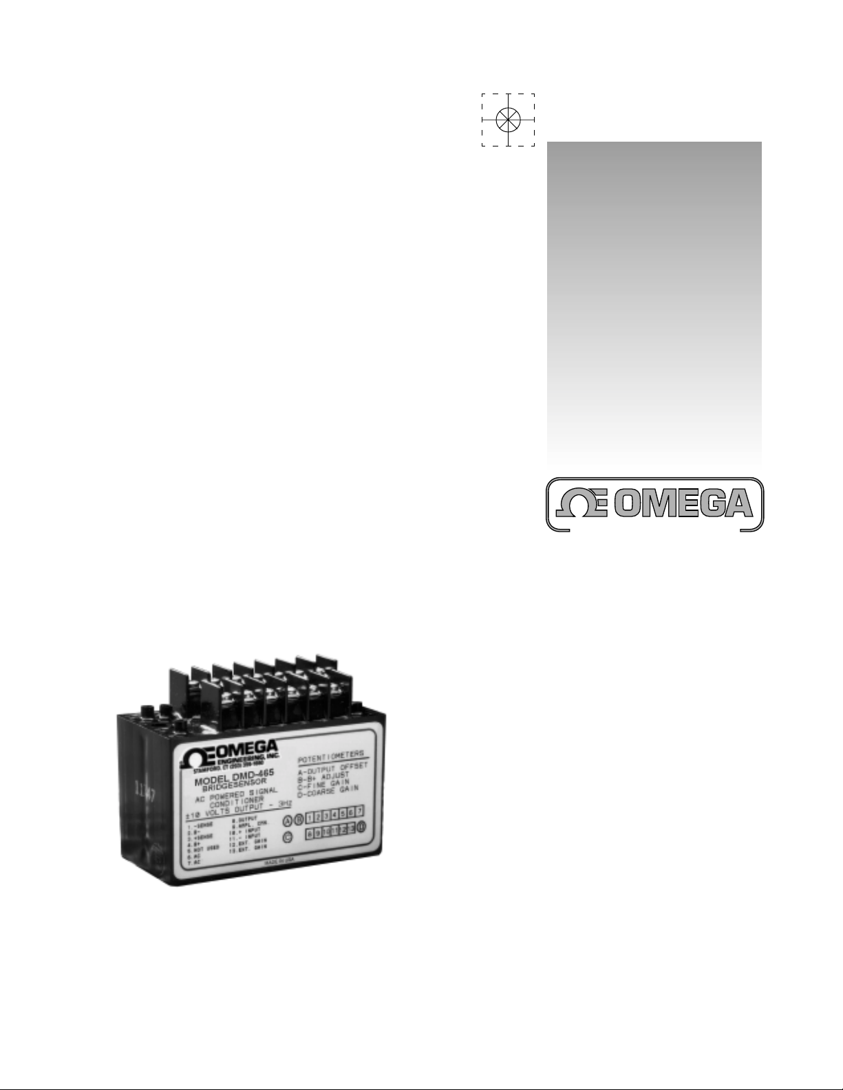
User’s Guide
®
An OMEGA Technologies Company
www.omega.com
e-mail:[email protected]
DMD-465 Bridgesensor
AC Powered Signal Conditioner
Page 2

®
Internet e-mailInternet e-mail
Internet e-mail
Internet e-mailInternet e-mail
OMEGAnetOMEGAnet
OMEGAnet
OMEGAnetOMEGAnet
http://wwwhttp://www
http://www
http://wwwhttp://www
omega.com
®®
®
®®
On-Line Service On-Line Service
On-Line Service
On-Line Service On-Line Service
.omega.com.omega.com
.omega.com
.omega.com.omega.com
®
Servicing North America:
USA:USA:
USA:
USA:USA:
ISO 9001 Certified Stamford, CT 06907-0047
Canada:Canada:
Canada:
Canada:Canada:
One Omega Drive, Box 4047
Tel: (203) 359-1660 FAX: (203) 359-7700
e-mail: [email protected]
976 Bergar
Laval (Quebec) H7L 5A1
Tel: (514) 856-6928 FAX: (514) 856-6886
e-mail: [email protected]
For immediate technical or application assistance:
USA and Canada:USA and Canada:
USA and Canada: Sales Service: 1-800-826-6342 / 1-800-TC-OMEGASM
USA and Canada:USA and Canada:
Customer Service: 1-800-622-2378 / 1-800-622-BESTSM
Engineering Service: 1-800-872-9436 / 1-800-USA-WHENSM
TELEX: 996404 EASYLINK: 62968934 CABLE: OMEGA
Mexico andMexico and
Mexico and
Mexico andMexico and
Latin America:Latin America:
Latin America: Tel: (95) 800-826-6342 FAX: (95) 203-359-7807
Latin America:Latin America:
En Español: (95) 203-359-7803 e-mail: [email protected]
Servicing Europe:
Benelux:Benelux:
Benelux: Postbus 8034, 1180 LA Amstelveen, The Netherlands
Benelux:Benelux:
Tel: (31) 20 6418405 FAX: (31) 20 6434643
Toll Free in Benelux: 0800 0993344
e-mail: [email protected]
Czech Republic:Czech Republic:
Czech Republic: ul. Rude armady 1868, 733 01 Karvina-Hranice
Czech Republic:Czech Republic:
Tel: 420 (69) 6311899 FAX: 420 (69) 6311114
Toll Free: 0800-1-66342
e-mail: [email protected]
France:France:
France: 9, rue Denis Papin, 78190 Trappes
France:France:
Tel: (33) 130-621-400 FAX: (33) 130-699-120
Toll Free in France: 0800-4-06342
e-mail: [email protected]
Germany/Austria:Germany/Austria:
Germany/Austria: Daimlerstrasse 26, D-75392 Deckenpfronn, Germany
Germany/Austria:Germany/Austria:
Tel: 49 (07056) 3017 FAX: 49 (07056) 8540
Toll Free in Germany: 0130 11 21 66
e-mail: [email protected]
United Kingdom:United Kingdom:
United Kingdom: One Omega Drive, River Bend T echnology Centr e
United Kingdom:United Kingdom:
ISO 9001 Certified Northbank, Irlam, Manchester
M44 5EX, England
Tel: 44 (161) 777-6611 FAX: 44 (161) 777-6622
Toll Free in the United Kingdom: 0800-488-488
e-mail: [email protected]
It is the policy of OMEGA to comply with all worldwide safety and EMC/EMI regulations that apply.
OMEGA is constantly pursuing certification of its products to the European New Approach Directives.
OMEGA will add the CE mark to every appropriate device upon certification.
The information contained in this document is believed to be correct, but OMEGA Engineering, Inc. accepts
no liability for any errors it contains, and reserves the right to alter specifications without notice.
WW
ARNINGARNING
W
ARNING: These products are not designed for use in, and should not be used for, patient-connected applications.
WW
ARNINGARNING
2
Page 3

Features
!
Rugged, Compact and Fully Encapsulated
!
Complete System - Just Add AC Power
!
Ready to Use with Screwdriver Wiring
!
Stable and Accurate
Applications
!
Weighing with Load Cells
!
Long Term Structural Monitoring
!
Process Control Pressure Transducers
!
Low Frequency Strain Measurements
Description
The Model 465 is a self contained, AC powered, signal
conditioningmoduleforbridgetypeinstrumentation. Itcontains
a precision differential instrumentation amplifier with filtered
output and a highly regulated, low noise, adjustable output
bridgeexcitationsource. Theunitiscompletelyencapsulated
for use in rugged environments.
Transducer Excitation
TransducerbridgeexcitationisprovidedbyanAClinepowered,
adjustable, well regulated, low noise power supply. The
excitation voltage is adjusted by means of a molded-in
potentiometer, which allows the output voltage to be varied
from 4 to 15 Volts. The output ripple is extremely low and the
line and load regulation are 0.05%.
The sense lines minimize variations in output voltage with
changesin load current or lead resistance. It should be noted
that if the sense feature is not being used, terminal 1 must be
connectedtoterminal2. Terminals3and4mustbeconnected
also. The supply will provide up to 150mA of output current.
Thesefeaturesmake the unit ideal for usewithmost common
strain gage bridge circuits of 120, 350, and 500 Ohms.
The supply has short circuit protection to protect it against
short term faults. The output recovers automatically from
short circuit conditions once the short is removed.
B+ VOLTAGE vs LOAD CURRENT
16
14
12
← SAFE OPERATING AREA →
10
8
6
B+ OUTPUT VOLYAGE (VOLTS)
4
0 20 40 60 80 100 120 140 160
FIGURE 1. Bridge Supply - Safe Operation
↑
↓
LOAD CURRENT (mA)
Safe Operation in the Unsafe Area
The curve (Figure 1) describes the region of safe operating
output current at each voltage setting level. If excitation is
desiredatthe4Voltlevelwith150mA,thiscanbeaccomplished
by using a resistor of at least 2 Watts in size in series with the
bridge. The right value resistor would drop 11 Volts allowing
4 Volts at 150mA across the bridge while minimizing internal
heatingoftheModel 465. The + sense line would regulate the
supply to the required 4 Volts. Normal operation of single
bridges at 10 Volts and under 100mA (all 120, 350, and 500
Ohm bridges) can be accomplished within the safe operating
area.
Instrumentation Amplifier
The built-in amplifier is a true differential input, low noise, low
drift, instrumentation amplifier. It has a high common mode
rejection ratio (CMRR) and is provided with an output offset
thatispotentiometeradjustable. The minimum gain setting of
the amplifier is 40 and the maximum gain using the built-in
potentiometer is 250. The gain may be adjusted up to a
maximumof1,000bymeansofan externalresistorconnected
across terminals 12 and 13. The size of the external resistor
canbe calculated using the gainformula in the specifications.
When doing this the coarse gain potentiometer should be
turned fully clockwise. The fine gain pot can then be used for
final gain adjustment. The output offset adjustment range is
±0.5V.
The amplifier can withstand input voltages up to 15 Volts
without damage. The output of the amplifier is filtered to be
3 dB down at 3 Hz using a double pole Butterworth response
filter to minimize the effects of high frequency electrical and
physical noise on the system. The output of the amplifier is
±10 Volts at 5mA making it compatible with modern data
acquisition techniques and systems.
3
Page 4

Specifications
(Typical @ 25°C unless noted)
reifilpmA
egnaRniaG052-04
Rlanretxehtiw000,1ot
tneiciffeoCerutarepmeTniaG/mpp002 °C
siseretsyHretemoitnetoPniaG.xamnapsfo%2.0
noitauqEniaG
V/Vniniag
)ITR(tfirD2±/VµG/02 °C
ecnadepmItupnI
laitnereffiD
edoMnommoC
001=niagta
zH001otzH1
)CD(04=niaGBd69
retliFhtrowrettuB
egatloVtupnI.xaM±V51
ylppuSegdirB
tupnI
egatloVtuptuOstloV51ot4
tnerruCtuptuOAm051ot5
I,V21=TUOV
L
esioNtuptuOSMRVm5.0
tfirD/mpp002 ° .xamC
noitalosIeniLCDV005,1
lacinahceM
thgieW)smarg015(.zo81
eziS
egatlovderisedehtsiG:etoN
tnerruCsaiBtupnI±An03
)OTR(esioNtuptuO
noitcejeRedoMnommoC
)daolk2(tuptuOdetaR±V01
egatloVedoMnommoC6±V5.
)CD(ecnadepmItuptuOsmho10.0
esnopseRcimanyD%1.0ots3.0
elopowtBd3-otCD
%50.0noitalugeReniL&daoL
Am001ot5=
siseretsyHretemoitnetoP+B.xamtuptuofo%3.0
tnerruCtiucriCtrohSAm057
erutarepmeTgnitarepO0° 07otC °C
erutarepmeTegarotS52- ° 58+otC °C
Rg = G-1 - 1
1
40 kΩ 150Ω
smhogem000,3
smhogem6
SMRVµ021
zH3
CAV511± zH06ot05%01
)evructnerrucsvegatlovtuptuoees(
Getting Started with the Model 465
I. Hook Up Procedure
A. Connect the +out of your load cell to the +INPUT,
pin 10.
B. Connect the -out of your load cell to the -INPUT,
pin 11.
Note: Ifthe±SENSEarenotusedinyourloadcellapplication,
the connections in stepC&Dneed to be followed. If
the ±SENSE are going to be used, do not jumper
them as described in stepsC&D.
C. Connect B+, pin 4, to the +excitation of your load cell
and jumper the +SENSE, pin 3, to B+, pin 4.
D. Connect B-, pin 2, to the -excitation of your load cell
and jumper the -SENSE, pin 1, to B-, pin 2.
E. Connect the VAC power supply to the AC input lines,
pins 6 and 7.
II. Turn On Procedure
A. Verify that the hook up procedure is complete.
B. Verifythecorrect AC voltage is applied to the 465; i.e.
100, 115, 220, 230.
C. Turn on the AC source supply to the 465.
D. Set the required EXCITATION supply voltage to the
load cell by adjusting B+ ADJUST, Pot B
III. Calibration Procedure for Zero Adjustment
)elbaliavaCAV032&022,001(
A. Jumper the + and - input terminals, pins 10 and 11,
together.
B. Connect a volt meter across the output, pins 8 and 9.
C. Adjust the OUTPUT OFFSET, Pot A, potentiometer
for zero.
IV. Full Scale Voltage Adjustment
A. Removethejumperbetweenthe+and-inputterminals
and apply a known load to your load cell, in most
cases it would be 100% of full scale.
B. Adjust the COARSE GAIN, Pot D, and FINE GAIN,
Pot C, potentiometers for the desired FULL SCALE
H"78.2xW"0.2xL"57.3
)mc(26.7x1.5x35.9
output.
C. Calibrationisnowcomplete.However,theusershould
recheck the ZERO & FULL SCALE output before
continuing.
Typical Bridge Application
Figure2showsatypicalloadcellapplication usingastandard
350 Ohm bridge. Typical bridge output is 2 or 3mV/Volt of
excitation. With the power supply excitation voltage at 10
Volts an output of 20 or 30mV from the bridge can be
obtained. The common mode voltage of the bridge (the
instrumentation amplifier input signal level) is 5 Volts. This
iswell within the 6.5Volt common mode voltage range of the
amplifier.
4
Page 5
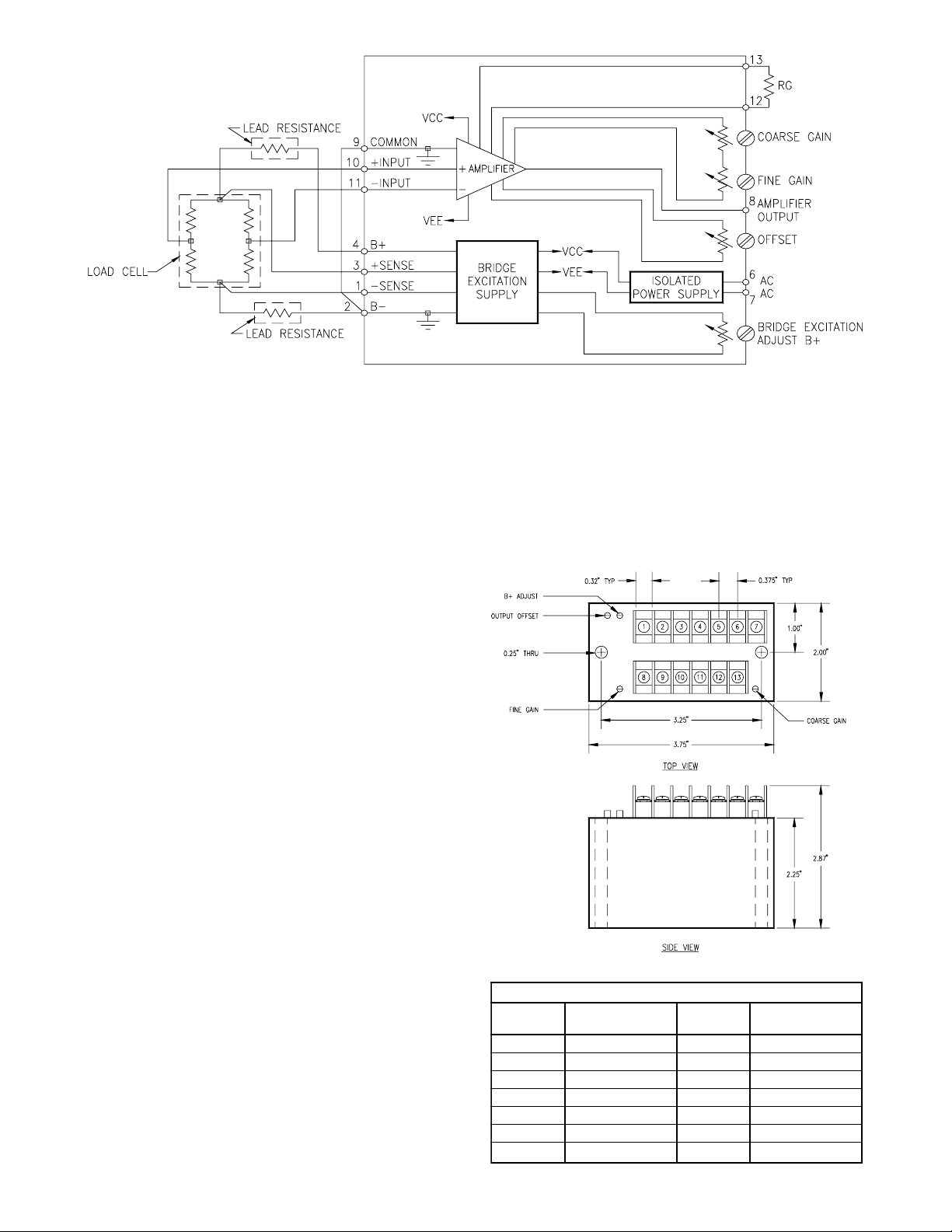
FIGURE 2. Typical load Cell Application
stnemngissApirtSlanimreT
wercS
lanimreT
noitcnuF
wercS
lanimreT
noitcnuF
1ESNES-8TUPTUO
2-B9 NMCREIFILPMA
3ESNES+01TUPNI+
4+B11TUPNI5DESUTON21NIAG.TXE
6CA31NIAG.TXE
7CA
Thegainmust be set between 300 and600dependingonthe
output of thebridge. Thebuilt-in potentiometer set to a gain
of 200 would achieve an output voltage of 4 to 6 Volts. For
a higher level output an external resistor must be used. The
value of that resistor can be calculated using the gain
formula. Itcanalsobearrivedat empiricallyusing acalibrated
inputsignal equal to the maximuminputsignal expected and
a resistance substitution box to adjust the gain until the
desired full scale output voltage is achieved.
Assuming a standard 350 Ohm bridge is used, the current
requiredfrom the excitation supply (setat 10 Volts) would be
28.6mA. If the leads were long enough to have 10 Ohms of
internal resistance there would be a drop of over 0.25 Volts
inboththe plus and common side ofthebridge. To eliminate
this potential error (especially where the current might vary
during the course of a measurement) the sense lines are
connected to measure and regulate the voltage right at the
bridge rather than at the output of the supply thereby
eliminating this potential source of error. The decision of
whether to use the sense leads or not depends entirely on
the lead length, its resistance and the effect of that error on
the measurement.
Application Suggestions
The Model 465 is designed to eliminate many of the ordinary
problems associated with bridge type measurements. Since
the whole system is in one case the common problem of
ground loops or circulating currents caused by poor wiring
practices is eliminated. It is recommended that lead lengths
be kept to a minimum. The use of shielded twisted pairs for
the input leads is recommended for most applications.
Tominimize self heating errors theuse of minimum excitation
powerissuggestedasissufficientheatsinkingofthetransducer
whereverpossible. For optimum stabilitya one hour warm-up
is recommended. Avoid large temperature changes or stray
magnetic fields.
The output leads should be kept short to minimize capacitive
loading on the output of the amplifier. The Model 465
Bridgesensor is ready to wire into your system, have power
applied, and to start making measurements for you.
Mechanical Specifications
Specifically designed for rugged field use the Model 465 is
completely encapsulated in epoxy using a vacuum potting
system to insure a complete seal against corrosive
environments. It is similarly protected against shock and
vibration and will provide years of reliable and accurate
operation.
FIGURE 3
5
Page 6

6
Page 7

WARRANTY/DISCLAIMER
OMEGA ENGINEERING, INC. warrants this unit to be free of defects in materials and workmanship for a period
of 13 months from date of purchase. OMEGA Warranty adds an additional one (1) month grace period to the
normal one (1) year product warranty to cover handling and shipping time. This ensures that OMEGA’s
customers receive maximum coverage on each product.
If the unit malfunctions, it must be returned to the factory for evaluation. OMEGA’s Customer Service Department
will issue an Authorized Return (AR) number immediately upon phone or written request. Upon examination by
OMEGA, if the unit is found to be defective, it will be repaired or replaced at no charge. OMEGA’s WARRANTY
does not apply to defects resulting from any action of the purchaser, including but not limited to mishandling,
improper interfacing, operation outside of design limits, improper repair, or unauthorized modification. This
WARRANTY is VOID if the unit shows evidence of having been tampered with or shows evidence of having
been damaged as a result of excessive corrosion; or current, heat, moisture or vibration; improper specification;
misapplication; misuse or other operating conditions outside of OMEGA’s control. Components which wear
are not warranted, including but not limited to contact points, fuses, and triacs.
OMEGA is pleased to offer suggestions on the use of its various products. However, OMEGA neither assumes
responsibility for any omissions or errors nor assumes liability for any damages that result from the use of its
products in accordance with information provided by OMEGA, either verbal or written. OMEGA warrants only
that the parts manufactured by it will be as specified and free of defects. OMEGA MAKES NO OTHER
WARRANTIES OR REPRESENTATIONS OF ANY KIND WHATSOEVER, EXPRESS OR IMPLIED, EXCEPT THAT
OF TITLE, AND ALL IMPLIED WARRANTIES INCLUDING ANY WARRANTY OF MERCHANTABILITY AND
FITNESS FOR A PARTICULAR PURPOSE ARE HEREBY DISCLAIMED. LIMITATION OF LIABILITY: The remedies
of purchaser set forth herein are exclusive, and the total liability of OMEGA with respect to this order, whether
based on contract, warranty, negligence, indemnification, strict liability or otherwise, shall not exceed the
purchase price of the component upon which liability is based. In no event shall OMEGA be liable for
consequential, incidental or special damages.
CONDITIONS: Equipment sold by OMEGA is not intended to be used, nor shall it be used: (1) as a “Basic
Component” under 10 CFR 21 (NRC), used in or with any nuclear installation or activity; or (2) in medical
applications or used on humans. Should any Product(s) be used in or with any nuclear installation or activity,
medical application, used on humans, or misused in any way, OMEGA assumes no responsibility as set forth
in our basic WARRANTY / DISCLAIMER language, and, additionally, purchaser will indemnify OMEGA and
hold OMEGA harmless from any liability or damage whatsoever arising out of the use of the Product(s) in such
a manner.
RETURN REQUESTS/INQUIRIES
Direct all warranty and repair requests/inquiries to the OMEGA Customer Service Department. BEFORE
RETURNING ANY PRODUCT(S) TO OMEGA, PURCHASER MUST OBTAIN AN AUTHORIZED RETURN (AR)
NUMBER FROM OMEGA’S CUSTOMER SERVICE DEPARTMENT (IN ORDER TO AVOID PROCESSING DELAYS).
The assigned AR number should then be marked on the outside of the return package and on any correspondence.
The purchaser is responsible for shipping charges, freight, insurance and proper packaging to prevent breakage
in transit.
FOR WARRANTY RETURNS, please have the
following information available BEFORE contacting
OMEGA:
1. Purchase Order number under which the
product was PURCHASED,
2. Model and serial number of the product
under warranty, and
3. Repair instructions and/or specific problems
relative to the product.
OMEGA’s policy is to make running changes, not model changes, whenever an improvement is possible. This affords our
customers the latest in technology and engineering.
OMEGA is a registered trademark of OMEGA ENGINEERING, INC.
Copyright 1999 OMEGA ENGINEERING, INC. All rights reserved. This document may not be copied, photocopied,
©
reproduced, translated, or reduced to any electronic medium or machine-readable form, in whole or in part, without the
prior written consent of OMEGA ENGINEERING, INC.
FOR NON-WARRANTY REPAIRS, consult OMEGA
for current repair charges. Have the following
information available BEFORE contacting
OMEGA:
1. Purchase Order number to cover the COST
of the repair,
2. Model and serial number of product, and
3. Repair instructions and/or specific problems
relative to the product.
7
Page 8

Where Do I Find Everything I Need for
Process Measurement and Control?
OMEGA...Of Course!
TEMPERATURE
" Thermocouple, RTD & Thermistor Probes, Connectors, Panels & Assemblies
" Wire: Thermocouple, RTD & Thermistor
" Calibrators & Ice Point References
" Recorders, Controllers & Process Monitors
" Infrared Pyrometers
PRESSURE, STRAIN AND FORCE
" Transducer & Strain Gauges
" Load Cells & Pressure Gauges
" Displacement Transducers
" Instrumentation & Accessories
FLOW/LEVEL
" Rotameters, Gas Mass Flowmeters & Flow Computers
" Air Velocity Indicators
" Turbine/Paddlewheel Systems
" Totalizers & Batch Controllers
pH/CONDUCTIVITY
" pH Electrodes, Testers & Accessories
" Benchtop/Laboratory Meters
" Controllers, Calibrators, Simulators & Pumps
" Industrial pH & Conductivity Equipment
DATA ACQUISITION
" Data Acquisition & Engineering Software
" Communications-Based Acquisition Systems
" Plug-in Cards for Apple, IBM & Compatibles
" Datalogging Systems
" Recorders, Printers & Plotters
HEATERS
" Heating Cable
" Cartridge & Strip Heaters
" Immersion & Band Heaters
" Flexible Heaters
" Laboratory Heaters
ENVIRONMENTAL
MONITORING AND CONTROL
" Metering & Control Instrumentation
" Refractometers
" Pumps & Tubing
" Air, Soil & Water Monitors
" Industrial Water & Wastewater Treatment
" pH, Conductivity & Dissolved Oxygen Instruments
M-0564/0501
8
 Loading...