

Page 1
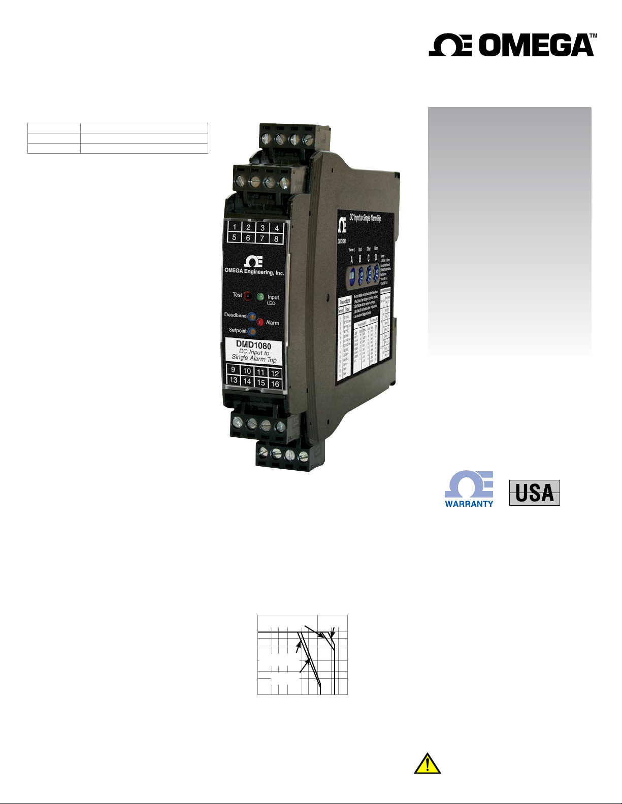
DMD1080
LifetimeTM
DMD1080-DC
DC Input Alarm Trips
M-5245/0818
Model Module Power
DMD1080
DMD1080-DC
Description
The DMD1080 accepts a DC voltage or current input and provide
visual alarm indication and alarm relay contact outputs. 15
voltage and 9 current input ranges can be field-configured via
external rotary and slide switches. Offset ranges such as 1-5
VDC and 4-20 mADC are also included.
Heavy-duty relay contacts allow the module to directly control
high capacity loads. Front-accessible potentiometers are used
to adjust the alarm setpoint from 0 to 100% and the deadband
from 1 to 100%.
The DMD1080 provides a single setpoint adjustment of the two
DPST relay contacts. The alarm output can be field configured
for HI or LO operation, latching or non-latching, and normal or
reverse acting. Deadband control can be adjusted from 1 to
100% and the alarm setpoint from 0 to 100%.
Sink/Source Input and Loop Supply
For maximum versatility, a current input can be selectively wired
for sinking or sourcing. This allows the DMD1080 to work with
powered or unpowered mA inputs. A regulated 15 VDC loop
excitation supply can be used to power passive input devices
eliminating the need for an additional DC loop supply.
Input and Alarm Status LEDs
The input LED varies in intensity with changes in the process
input signal. A red/green bi-color alarm status LED visually
indicate alarm status. These LEDs provide a quick visual status
of your process at all times.
85-265 VAC, 50/60 Hz or 60-300 VDC
9-30 VDC or 10-32 VAC
User’s Guide
Shop online at
omega.com
e-mail: [email protected]
For latest product manuals:
Output Test / Unlatch
A functional test button can be used to verify the alarm and
system operation and also provides the additional function of
unlatching the alarm when the latching mode has been selected.
The output test button greatly aids in saving time during initial
startup and/or troubleshooting.
DC Input Ranges
24 field selectable ranges via switch settings
See chart on next page
Voltage: 0-50 mVDC to 0-10 VDC
Bipolar Voltage: ±5 VDC or ±10 VDC
Current: 0-1 mADC to 0-20 mADC, 4-20 mADC
Input Impedance and Burden
Voltage: 250 kΩ minimum
Current: 50 Ω typical
Voltage burden: 1 VDC at 20 mA current input
Isolation
Power to input isolation: 1200 V
Common mode protection: 600 VACp or 600 VDC
Input Loop Power Supply
15 VDC ±10%, regulated, 25 mADC, max. ripple, <10 mVRMS
May be selectively wired for sinking or sourcing mA input
LoopTracker
Variable brightness LED indicates input loop level and status
Relay Output
Single setpoint dual DPST contact sets, field configurable
2 Form A (NO) and 2 Form B (NC) contact sets (8 terminals)
May be field wired for Form C operation
Relay Contact Ratings
8 A @ 240 VAC resistive load
5 A @ 240 VAC inductive load (cos f = 0.4)
8 A @ 30 VDC resistive load
3.5 A @ 30 VDC inductive load (L/R = 7ms)
See diagram on other side
External contact protection such as an RC snubber is recommended for inductive loads
Relay Contact Ratings
AC inductive load
(cos f = 0.4)
8
5
3
DC inductive load
1
(L/R = 7 ms)
0.5
DC resistive
0.3
Switching Current (A)
0.1
load
0 3 5 10 30 50 100 300 500
Switching Voltage (V)
AC resistive
load
www.omegamanual.info
MADE IN
Setpoint
12 turn potentiometer adjustable from 0 to 100% of span
Deadband
12 turn potentiometer adjustable from 1 to 100% of span
Output Test/Reset Button
Toggles relay to opposite state when pressed
Resets latching relay if latching relay mode is selected
Response Time
70 milliseconds typical
Ambient Temperature Range and Stability
–10°C to +60°C operating ambient
Better than 1% of span over operating temperature range
Better than 0.02% of span per °C
Power
85-265 VAC, 50/60 Hz or 60-300 VDC, 2 W maximum
D versions: 9-30 VDC or 10-32 VAC 50/60 Hz, 2 W maximum
Housing and Connectors
IP 40, requires installation in panel or enclosure
For use in Pollution Degree 2 Environment
Mount vertically to a 35 mm DIN rail
Four 4-terminal removable connectors, 14 AWG max wire size
WARNING: This product can expose you to chemicals including nickel, which are known to the State of California to cause
cancer or birth defects or other reproductive harm. For more
information go to www.P65Warnings.ca.gov
Page 2
2
DMD1080, DMD1080-DC DC Input Alarm Trips
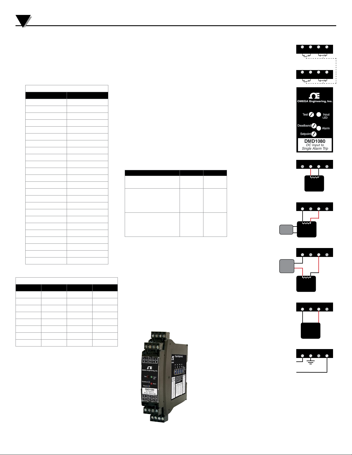
Range Selection
It is generally easier to select ranges before installation. See the
model/serial number label for module information, options, or if
a custom range was specified.
Set input selector switch A to “I” for a current input or to “V”
for a voltage input.
Switch settings B and C determine the input range.
Switch D determines the alarm configuration.
Input Configuration Settings
Input Range Switch A B C
0-50 mV
0-100 mV
0-200 mV
0-250 mV
0-400 mV
0-500 mV
0-1 V
0-2 V
0-2.5 V
0-4 V
1-5 V
0-5 V
0-10 V
±5 V
±10 V
0-1 mA
0-2 mA
0-4 mA
0-8 mA
2-10 mA
0-10 mA
0-16 mA
4-20 mA
0-20 mA
V81
V91
VA1
VC1
VB1
V01
V11
V21
V41
V31
V3F
V51
V61
V64
V74
IC1
I01
I11
I21
I2F
I41
I31
I3F
I51
Alarm Configuration Settings
Alarm Type Latch Action Switch D
HI No Normal
HI No Reverse
HI Yes Normal
HI Yes Reverse
LO No Normal
LO No Reverse
LO Yes Normal
LO Yes Reverse
2
6
0
4
3
7
1
5
Electrical Connections
WARNING! All wiring must be performed by a qualified electrician or instrumentation engineer. See diagrams for terminal
designations and wiring examples.
Avoid shock hazards! Turn power off to signal input, relay wiring,
and module power before connecting or disconnecting wiring.
Module Power Terminals
Check white model/serial number label for module operating
voltage to make sure it matches available power.
When using DC power, either polarity is acceptable, but for
consistency with similar products, positive (+) can be wired to
terminal 13 and negative (–) can be wired to terminal 16.
Signal Input Terminals
Polarity must be observed for input wiring connections. If the input
does not function, check switch settings and wiring polarity.
Voltage inputs are connected as shown in the table below.
The input can be used with either sinking or sourcing milliamp
devices. Only one device must provide power to the current loop.
For a transmitter with a current output, determine if it provides
power to the current loop or if it must be powered by the DMD
1080 module. Use a multi-meter to check for voltage at the
transmitter’s output terminals. Typical voltage may be in the
range of 9 to 24 VDC. In this case, wire the device to terminals
9 and 11.
Type of Input Device – Terminal + Terminal
Sensor or transmitter with a voltage output.
9 (–) 11 (+)
Transmitter with a mA (current)
output that provides power to
the current loop. Typically a 3 or
9 (–) 11 (+)
4-wire device.
Transmitter with mA (current)
output that is unpowered.
Typically a 2-wire device. DMD
11 (–)
Signal
10 (+15 V)
module provides loop power.
Relay Output Terminals
See wiring diagrams for connections. The module does not
provide power to the relay contacts.
Inductive loads (motors, solenoids, contactors, etc.) will greatly
shorten relay contact life unless an appropriate RC snubber is
installed.
The DMD1080 operates two sets of relays in unison with a
single setpoint.
The dual DPST contact sets are in a Form A (NO) and a Form B
(NC) configuration.
They may be field wired for Form C operation as required.
1 2 3 4
Relay 1
5 6 7 8
Relay 2
Wire terminal torque
0.5Nm to 0.6Nm
(4.4 to 5.3 in-lbs)
To avoid damage
to the module,
do not make any
connections to
unused terminals
To maintain full isolation avoid combining
Input
Power
9 10 11
13 14
12
15
16
power supplies in
common with input,
output, or unit power.
Form A Form B
NO NO NC NC
21 3 4
Relay Outputs
Jumper
2 & 3 for
Form C
operation
Single setpoint
dual DPST
Jumper
6 & 7 for
Form C
operation
Form A Form B
NO NO NC NC
65 7 8
Test: Push to toggle relays to opposite state
Input LED: Variable brightness green
LED indicates input level
Bi-Color Alarm LED
Green = non-alarm condition
Red = alarm condition
Deadband: Smaller = counterclockwise. Symmetrical about setpoint
Setpoint: Higher = clockwise
Current Sourcing Input
DMD1080 provides
power to input loop.
Typical when using a
passive or unpowered
transmitter or sensor.
Current Sinking Input
Typical of a system
using a transmitter that
is externally powered
and provides power to
the loop.
Current Sinking Input
with Separate Power
Supply
Typical of a system using
a passive transmitter and
a loop power supply to
power to the loop.
Power
Source
Loop
Power
Source
109 11 12
+15V –
Passive
109 11 12
–
mA Xmtr
109 11 12
–
+ –
Passive
mA
Xmtr
+
Ri
+
Ri
mA Xmtr
109 11 12
Voltage Input
Typical of a system using
– +
a transmitter that has a
voltage output.
Voltage
Device
1413 15 16
13 Power AC or DC +
14 Earth Ground
16 Power AC or DC –
DMD1080: 85-265 VAC, 50/60 Hz or 60-300 VDC
DMD1080-DC: 9-30 VDC or 10-32 VAC 50/60 Hz
Ri
Page 3
DMD1080, DMD1080-DC DC Input Alarm Trips
3
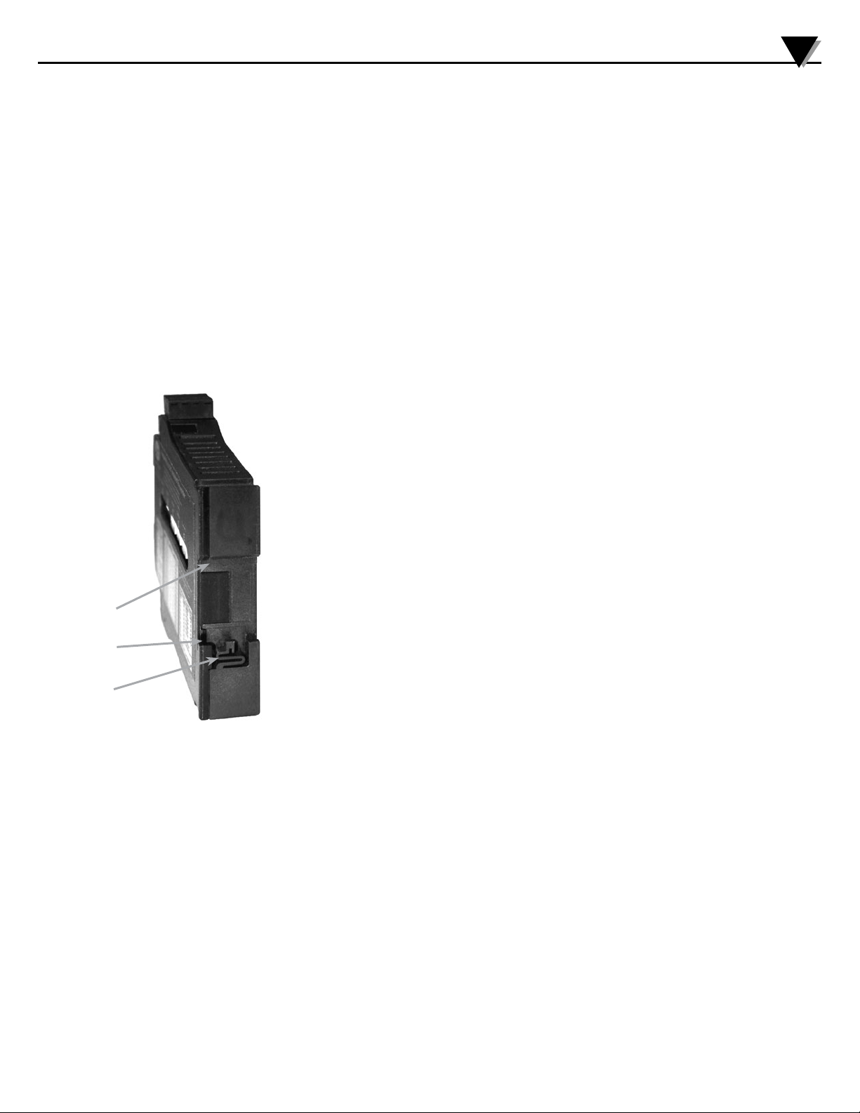
Mounting to a DIN Rail
Install module vertically on a 35 mm DIN rail in a protective
enclosure away from heat sources.
Do not block air flow. Allow 1” (25 mm) above and below housing vents for air circulation.
Precautions
WARNING! Avoid shock hazards! Turn signal input, output, and
power off before connecting or disconnecting wiring, or removing or installing module.
Installation
1. Tilt front of module downward and position the lower mounts
and spring clips against the bottom edge of DIN rail.
2. Clip Lower Mount to bottom edge of DIN rail.
3. Push front of module upward until upper mount snaps into
place.
Removal
1. Push up on bottom back of module.
2. Tilt front of module downward to release upper mount from
top edge of DIN rail.
3.The module can now be removed from the DIN rail.
Setup and Calibration
The input ranges are factory calibrated and do not require
adjustment.
The Setpoint potentiometer allows the operator to adjust the
level at which the alarm is activated. This control is adjustable
from 0 to 100% of the input range.
The Deadband potentiometer allows the alarm trip and reset
window to be adjusted symmetrically about the setpoint from 1
to 100% of the span. This allows the operator to fine tune the
point at which the alarm trips and resets.
The deadband is typically used to prevent chattering of the
relays or false trips when the process signal is unstable or
changes rapidly.
To calibrate the alarm section, set the deadband control to the
minimum (counterclockwise).
Set the signal source to a reference that represents the desired
trip point.
Adjust the setpoint control to the point at which the relay changes state form a non-alarm to an alarm condition. The deadband
will be 1.0% of span in this case.
If a larger amount of deadband is desired turn the deadband
potentiometer clockwise. The deadband is symmetrical about
the setpoint; both transition points will change as deadband is
increased.
Output Test Function
When the test button is depressed it will drive the relays to their
opposite state. This can be used as a diagnostic aid during initial
start-up or troubleshooting. When released, the relays will return
to their prior states.
Operation
The green input LED provides a visual indication that a signal
is being sensed by the input circuitry of the module. It also
indicates the input signal strength by changing in intensity as
the process changes from minimum to maximum.
If the LED fails to illuminate, or fails to change in intensity as
the process changes, check the module power or signal input
wiring. Note that it may be difficult to see the LEDs under bright
lighting conditions.
The bi-color alarm LED provides a visual indication of the alarm
status. In all configurations, a green LED indicates a non-alarm
condition and a red LED indicates an alarm condition.
In the normal mode of operation, the relay coil is energized in
a non-alarm condition and de-energized in an alarm condition.
This will create an alarm condition if the module loses power.
For a normal acting, non-latching configuration, the alarm will
activate when the input signal exceeds the setpoint (HI alarm) or
falls below the setpoint (LO alarm), then will automatically reset
when the alarm condition no longer exists.
For a reverse acting alarm, the relay coil is de-energized in a
non-alarm condition and energized in an alarm condition. The
alarm activates when the input signal exceeds the setpoint (HI
alarm) or falls below the setpoint (LO alarm), then automatically
resets when the alarm condition no longer exists.
When the latching mode is selected, it will be necessary to push
the functional test button or remove power from the module to
reset the alarm. The alarm will only reset if the alarm condition
no longer exists.
Upper Mount
Lower Mount
Spring Clip
Page 4

WARRANTY/DISCLAIMER
OMEGA ENGINEERING, INC. warrants this unit to be free of defects in materials and workmanship for a
period of 13 months from date of purchase. OMEGA’s WARRANTY adds an additional one (1) month
grace period to the normal one (1) year product warranty to cover handling and shipping time. This
ensures that OMEGA’s customers receive maximum coverage on each product.
If the unit malfunctions, it must be returned to the factory for evaluation. OMEGA’s Customer Service
Department will issue an Authorized Return (AR) number immediately upon phone or written request.
Upon examination by OMEGA, if the unit is found to be defective, it will be repaired or replaced at no
charge. OMEGA’s WARRANTY does not apply to defects resulting from any action of the purchaser,
including but not limited to mishandling, improper interfacing, operation outside of design limits,
improper repair, or unauthorized modification. This WARRANTY is VOID if the unit shows evidence of
having been tampered with or shows evidence of having been damaged as a result of excessive corrosion;
or current, heat, moisture or vibration; improper specification; misapplication; misuse or other operating
conditions outside of OMEGA’s control. Components in which wear is not warranted, include but are not
limited to contact points, fuses, and triacs.
OMEGA is pleased to offer suggestions on the use of its various products. However,
OMEGA neither assumes responsibility for any omissions or errors nor assumes liability for
any damages that result from the use of its products in accordance with information provided
by OMEGA, either verbal or written. OMEGA warrants only that the parts manufactured by the
company will be as specified and free of defects. OMEGA MAKES NO OTHER WARRANTIES OR
REPRESENTATIONS OF ANY KIND WHATSOEVER, EXPRESSED OR IMPLIED, EXCEPT THAT OF
TITLE, AND ALL IMPLIED WARRANTIES INCLUDING ANY WARRANTY OF MERCHANTABILITY
AND FITNESS FOR A PARTICULAR PURPOSE ARE HEREBY DISCLAIMED. LIMITATION OF
LIABILITY: The remedies of purchaser set forth herein are exclusive, and the total liability of
OMEGA with respect to this order, whether based on contract, warranty, negligence,
indemnification, strict liability or otherwise, shall not exceed the purchase price of the
component upon which liability is based. In no event shall OMEGA be liable for
consequential, incidental or special damages.
CONDITIONS: Equipment sold by OMEGA is not intended to be used, nor shall it be used: (1) as a “Basic
Component” under 10 CFR 21 (NRC), used in or with any nuclear installation or activity; or (2) in medical
applications or used on humans. Should any Product(s) be used in or with any nuclear installation or
activity, medical application, used on humans, or misused in any way, OMEGA assumes no responsibility
as set forth in our basic WARRANTY/DISCLAIMER language, and, additionally, purchaser will indemnify
OMEGA and hold OMEGA harmless from any liability or damage whatsoever arising out of the use of the
Product(s) in such a manner.
RETURN REQUESTS/INQUIRIES
Direct all warranty and repair requests/inquiries to the OMEGA Customer Service Department.
BEFORE RETURNING ANY PRODUCT(S) TO OMEGA, PURCHASER MUST OBTAIN AN AUTHORIZED
RETURN (AR) NUMBER FROM OMEGA’S CUSTOMER SERVICE DEPARTMENT (IN ORDER TO AVOID
PROCESSING DELAYS). The assigned AR number should then be marked on the outside of the return
package and on any correspondence.
The purchaser is responsible for shipping charges, freight, insurance and proper packaging to prevent
breakage in transit.
FOR WARRANTY RETURNS, please have the
following information available BEFORE contacting
OMEGA:
1. Purchase Order number under which the product
was PURCHASED,
2. Model and serial number of the product under
warranty, and
3. Repair instructions and/or specific problems
relative to the product.
OMEGA’s policy is to make running changes, not model changes, whenever an improvement is possible. This affords
our customers the latest in technology and engineering.
OMEGA is a registered trademark of OMEGA ENGINEERING, INC.
© Copyright 2017 OMEGA ENGINEERING, INC. All rights reserved. This document may not be copied, photocopied,
reproduced, translated, or reduced to any electronic medium or machine-readable form, in whole or in part, without the
prior written consent of OMEGA ENGINEERING, INC.
FOR NON-WARRANTY REPAIRS,
OMEGA for current repair charges. Have
the following information available BEFORE
contacting OMEGA:
1. Purchase Order number to cover the COST
of the repair,
2. Model and serial number of the product, and
3. Repair instructions and/or specific problems
relative to the product.
consult
 Loading...