

Page 1
®
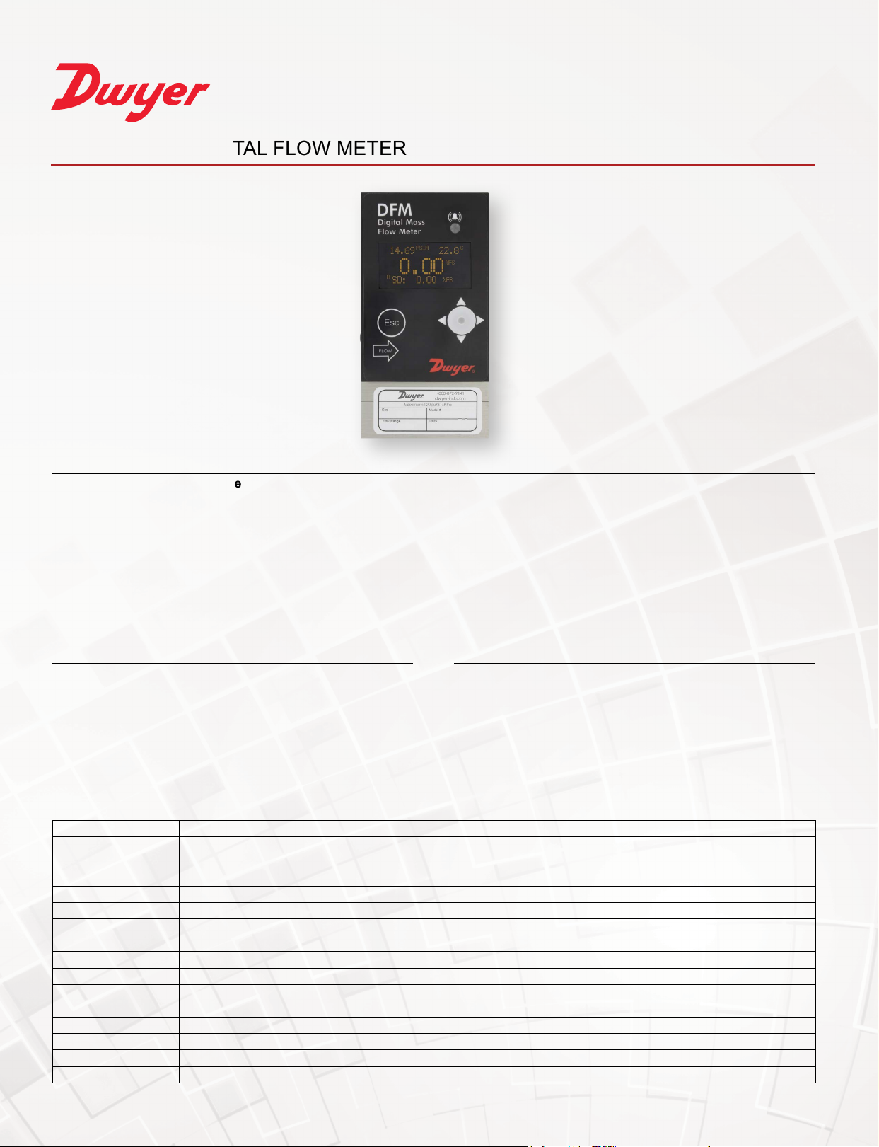
SERIES DFM | DIGITAL FLOW METER
BENEFITS/FEATURES
• Quick (<20 ms) response time
• Multi-parameter functionality
• Multi-gas functionality
• Capable of storing up to 90 gases and 20 custom gas mixes
•Simpleeldconguration
•Modiableoutputs
•High,loworin-rangealarmswithpresetactiondelayformassow,temperatureandpressure
DESCRIPTIONAPPLICATIONS
• Gas ow measurement
• Operating pumps and valves
• Process equipment
• Scientic and analytical
• Bioreactors and surface depositions
• Gas sampling
• General manufacturing
The Series DFM Digital Flow Meter is the industry leader in the
measurement of mass and volumetric ow rates of process gases.
Using the OLED/joystick interface, the owmeter can measure up to 30
different gases. Simultaneous displays of mass ow, volumetric ow,
pressure and temperature parameters promote applications in a variety
of industries.
SPECIFICATIONS
Service Clean, non-corrosive gases compatible with wetted parts.
Wetted Materials 316 SS, 416 SS, high temperature polyamide, alumina ceramic, epoxy, silicone, glass, gold. FKM O-rings.
Accuracy ±(0.5% of reading + 0.2% FS).
Repeatability ±0.15% FS.
Response Time 10 ms.
Output 0-5 VDC, 0-10 VDC and 4-20 mA.
Relay Rating Programmable solid state relay.
Max. Particulate Size 20 microns.
Temperature Limits 14 to 140°F (-10 to 60°C).
Power Supply 9-26 VDC.
Process Connections 1/8˝ compression tting for ow rates ≤ 10 L/min; 1/4˝ for ≤ 50 L/min; 3/8˝ for ≤ 100 L/min.
Display 2 x 16 character OLED (model selectable).
Pressure Limits 120 psig (8.27 bar).
Leak Integrity 1 x 10
Weight DFM-01/50: 0.85 lb (0.4 kg); DFM-51/56: 1.15 lb (0.52 kg).
Agency Approvals CE.
-9
sccs of helium.
Page 2
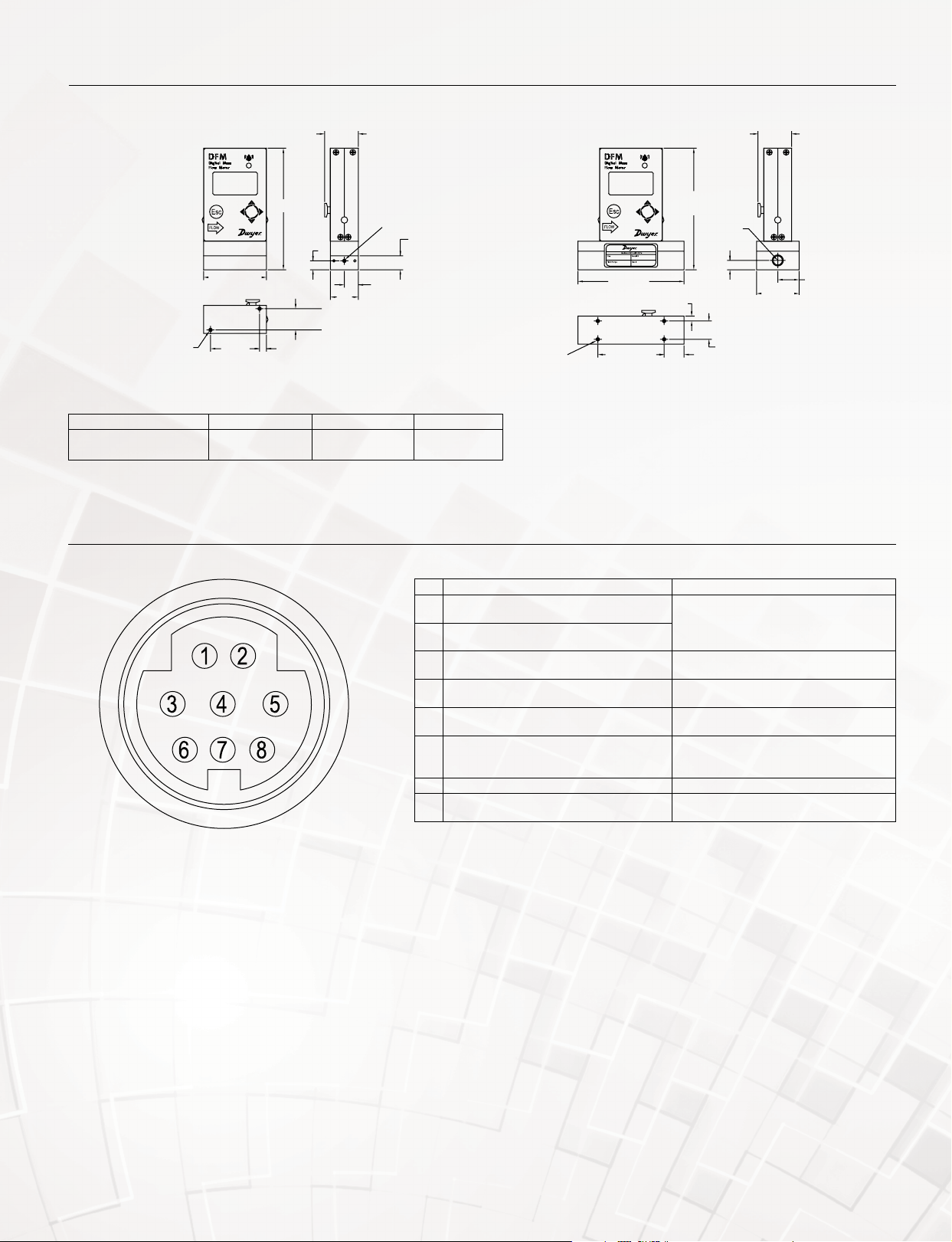
DIMENSIONS
TIP RX [-]
PHONEJACK
ADDRESS: FF
RS-232 SIGNAL AND GND
1-17/64
Ø0.22 2 HOLES
1-17/64
[19.05]
[20.32]
[32.26]
6-32 UNC-2B
2-3/8 [60.45]
1-27/32
[46.99]
A
51/64 [20.32]
17/64 [6.73]
B
1-3/64
[26.67]
C
[2 PORTS]
17/32
[13.34]
Range A B C
0.5 mL/min-50 mL/min
51 mL/min-20 L/min
4-13/32 [111.76]
4-37/64 [116.33]
4-37/64 [116.33]
4-13/32 [111.76]
WIRING DIAGRAM
17/32
[13.34]
10-32 UNF-2B
1/8-27 NPT
8-32 UNC-2B
Ø0.30 [4] HOLES
Ranges 21 L/min-100 L/min (DFM-51/56)Ranges 0.5 mL/min-20L/min (DFM-01/50)
4 [101.60]
2-1/2 [63.50]
3/16 [4.57]
3/4
4-27/32
[123.19]
1/4-18 NPT
[2 PORTS]
31/64
[12.45]
1-1/4
[31.75]
[32.26]
1-19/32
[40.64]
51/64
DIN connector wiring
PIN Function Note
Solid state SPST relay NO (normally open)
1
contact #1
Solid state SPST relay NO (normally open)
2
contact #2
RS-232 RX/RS-485 (-) communication
3
interface input
Analog (0-5 VDC, 0-10 VDC, 4-20 mA) input/
4
output reference (-)
RS-232 TX / RS-485(+) communication
5
interface input
Analog (0-5 VDC, 0-10 VDC or 4-20 mA)
6
output (+)
Power supply, positive (+) Power input 9-26 VDC.
7
Power supply, common (-)
8
RS-232 signal ground
Do not exceed SSR maximum voltage 48 AC
peak/DC and maximum load current 400 mA.
Also accessible via audio jack connector (see
gures 2 and 25 in IOM).
Common (return) for pin 6 (0-5 VDC or 0-10
VDC or 4-20 mA).
Also accessible via audio jack connector (see
gures 2 and 25 in IOM).
Output. Do not apply external voltage or
any current source. Be sure to observe
recommended load impedance.
Power input and RS-232 communication
common.
Page 3
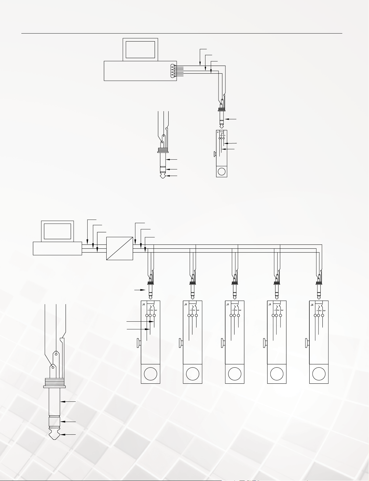
WIRING DIAGRAM
TIP RX [-]
PHONEJACK
ADDRESS: FF
RS-232 SIGNAL AND GND
HOST PC
WITH RS-232 INTERFACE
NOTE: CROSSOVER CONNECTION
HAS TO BE ESTABLISHED.
RX [-] TX [+] GND
RS-232 SIGNAL GND
X
X
X
X
X
X
SLEEVE GND
RING TX [+]
RS-232 wiring (default)
RS-232 TX
RS-232 RX
STEREO
TX [+]
RX [-]
HOST PC WITH
RS-232 INTERFACE
RX [-] TX [+] GND
WHITE
RED
PHONEJACK STEREO
SHIELD
SLEEVE GND
RS-232 RX
RS-232 TX
RS-232
RS-485
TX [+]
RX [-]
NOTES:
1. RS-232 TO RS-485 CONVERTER HAS TO BE CONFIGURED FOR 2 WIRE HALF DUPLEX SYSTEM.
2. UP TO 64 DEVICES ON ONE RS-485 SEGMENT, UP TO 2000 FEET.
GND
T [-]
T [+]
DFM #1 DFM #2 DFM #3 DFM #4 DFM #64
ADDRESS: 11 ADDRESS: 12 ADDRESS: 13 ADDRESS: 14
RING TX [+]
TIP RX [-]
RS-485 wiring (display selectable)
Page 4
®
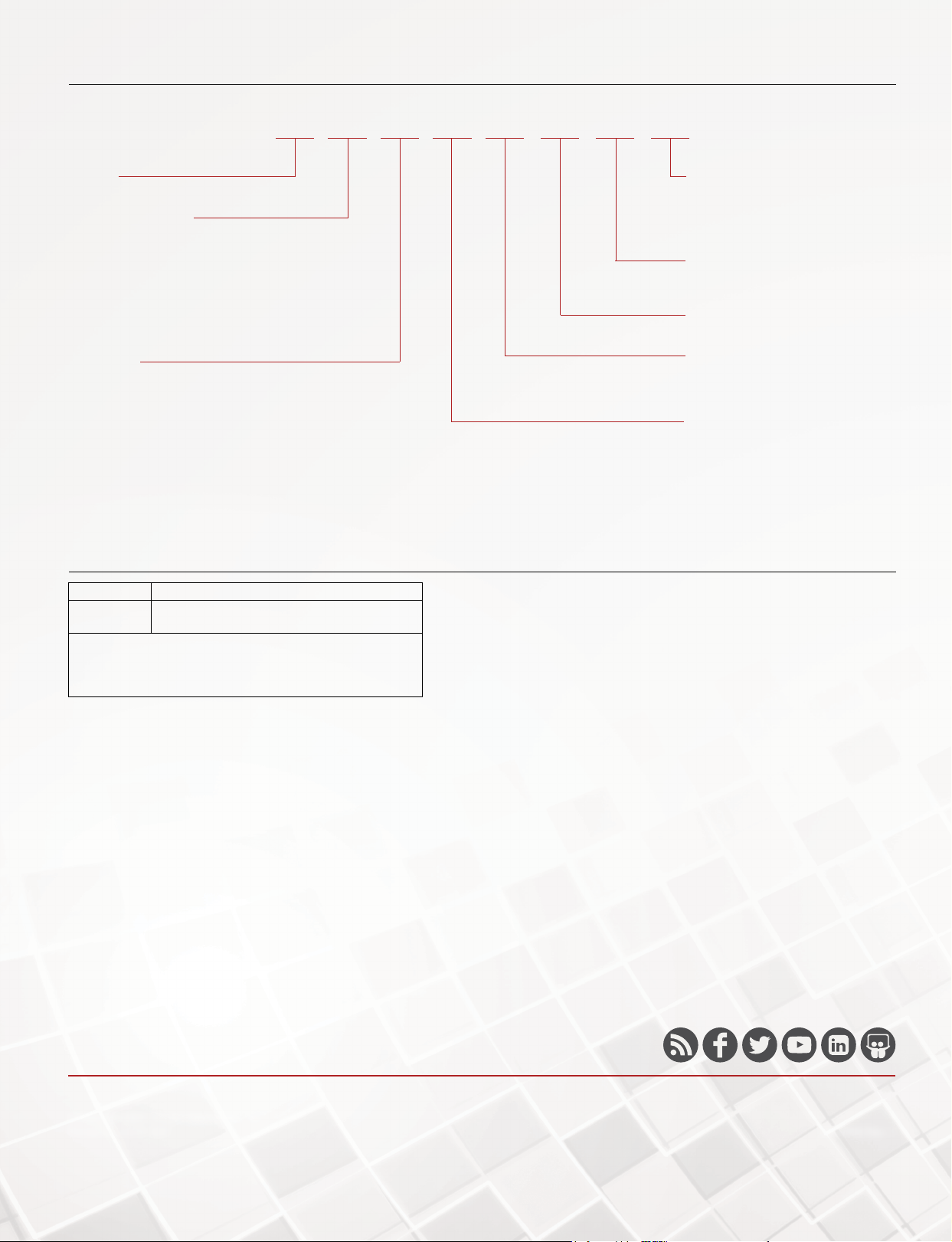
HOW TO ORDER
Use the bold characters from the chart below to construct a product code.
DFM -22 010 -V
SERIES
DFM: Digital ow controller
PRESSURE RANGE*
-22: 0 to 100 mL/min
-26: 0 to 200 mL/min
-32: 0 to 500 mL/min
-37: 0 to 1000 mL/min
-39: 0 to 2 L/min
-43: 0 to 5 L/min
-48: 0 to 10 L/min
-56: 0 to 100 L/min
BODY SIZE
005: Very low ow
010: Low ow
050: Medium ow
100: High ow
*Consult factory for ranges up from 0-0.5 mL/min to 0-100 L/min.
ACCESSORIES
L 2-A A
DIGITAL INTERFACE
2: RS-232 default (RS-485 display
selectable)
3: RS-232 with Modbus® (RS-485
display selectable)
OUTPUT SIGNAL
A: 0-5 VDC default (4-20 mA, 0-10
VDC display selectable)
DISPLAY
L: LED display
FITTINGS
-A: 1/8˝ compression (very low, low)
-B: 1/4˝ compression (medium)
-D: 3/8˝ compression (high)
SEAL MATERIAL
-V: Fluoroelastomer
Model Description
GFM-110P
GFM-220PE
110 V power supply
220 V power supply
Note: 1.5 ft RS-232 interface 3-wire 9-pin D connector
included. For RS-485 contact factory for A-DFM-CBL-A485DP
3 ft RS-485 3.5 mm stereo-audio connection with stripped ends
available for purchase.
Modbus® is a registered trademark of Schneider Automation, Inc.
DWYER INSTRUMENTS, INC.
©Copyright 2021 Dwyer Instruments, Inc.
Printed in U.S.A. 5/21 DS-DFM Rev. 1
Important Notice: Dwyer Instruments, Inc. reserves the right to make changes to or discontinue any product or service identied in this publication without notice. Dwyer advises its customers to obtain the
latest version of the relevant information to verify, before placing any orders, that the information being relied upon is current.
 Loading...