

Page 1
Page 2
OMEGAnetsm On-Line Service
http://www.omega.com
Internet e-mail
Servicing North America:
USA: One Omega Drive, Box 4047
ISO 9001 Certied Stamford, CT 06907-0047
TEL: (203) 359-1660 FAX: (203) 359-7700
e-mail: [email protected]
Canada: 976 Bergar
Laval (Quebec) H7L 5A1
TEL: (514) 856-6928 FAX: (514) 856-6886
e-mail: [email protected]
For immediate technical or application assistance:
USA and Canada: Sales Service: 1-800-826-6342 / 1-800-TC-OMEGA
Customer Service: 1-800-622-2378 / 1-800-622-BEST
Engineering Service: 1-800-872-9436 / 1-800-USA-WHEN
TELEX: 996404 EASYLINK: 62968934 CABLE: OMEGA
Mexico: TEL: (001) 800-826-6342 FAX: (001) 203-359-7807
En Espanol: (001) 203-359-7803 email: [email protected]
[email protected]
Servicing Europe:
Benelux: Postbus 8034, 1180 LA Amstelveen, The Netherlands
TEL: +31 (0)20 6418405 FAX: +31 (0)20 6434643
Toll Free in Benelux: 0800 0993344
e-mail: [email protected]
Czech Republic: Rude armady 1868, 733 01 Karvina 8
TEL: +420 (0)69 6311899 FAX: +420 (0)69 6311114
Toll Free in Czech Republic: 0800-1-66342 e-mail: [email protected]
France: 9, rue Denis Papin, 78190 Trappes
TEL: +33 (0)130 621 400 FAX: +33 (0)130 699 120
Toll Free in France: 0800-4-06342
e-mail: [email protected]
Germany/Austria: Daimlerstrasse 26, D-75392 Deckenpfronn, Germany
TEL: +49 (0) 7056 3017 FAX: +49 (0)7056 8540
Toll Free in Germany: -800 TC-OMEGA
e-mail: [email protected]
United Kingdom: One Omega Drive, River Bend Technology Centre
ISO 9002 Certied Northbank, Irlam, Manchester
M44 5EX, England
TEL: +44 (0)161 777 6611 FAX: +44 (0)161 777 6622
Toll Free in England: 0800 488 488
e-mail: [email protected]
It is the policy of OMEGA to comply with all worldwide safety and EMC/EMI regulations that apply. OMEGA is constantly pursuing certication of its
products to the European New Approach Directives. OMEGA will add the CE mark to every appropriate device upon certication.
The information contained in this document is believed to be correct, but OMEGA Engineering, Inc. accepts no liability for any errors it contains, and
reserves the right to alter specications without notice.
WARNING: These products are not designed for use in, and should not be used for, patient connected applications.
Page 3
INTRODUCTION
Congratulations on selecting the DFG21 Series force gauge for your precision load measurement requirements. Please read this manual and understand gauge operation before attempting to use this instrument. Follow all precautions and adhere to all Warnings, Cautions and Notes.
PRECAUTIONS
n Read the DFG21 Series User’s Guide completely before attempting to use this precision force measuring instrument. By following the instruc-
tions contained in this manual, the optimum accuracy and performance can be attained.
n Never operate the DFG21 Series gauge with the cover removed.
n Verify Input Power Source BEFORE charging the DFG21 Series battery or before operating the gauge using AC power.
n Never use the DFG21 Series gauge in a manner not specied by OMEGA ENGINEERING. Contact Omega Engineering for assistance if you
do not understand how to operate your force gauge.
n Obey all warning labels on your DFG21 Series gauge.
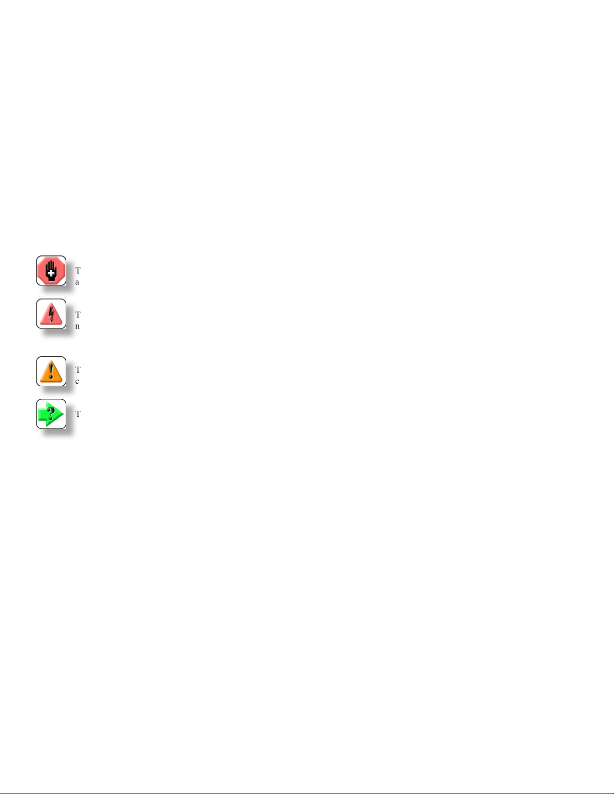
ICONS
WARNING
The raised hand icon warns of a situation or condition that may lead to personal injury or death. Do not proceed until the warning is read
and thoroughly understood. Warning messages are shown in bold type.
DANGEROUS VOLTAGE
The lightning icon warns of the presence of an uninsulated dangerous voltage within the product enclosure that might be of sufcient magnitude to cause serious shocks or death. Never open the enclosures unless you are an authorized and qualied Omega service personnel.
Never open any enclosure when power is connected to the system or its components.
CAUTION
The exclamation point icon indicates a situation or condition that may lead to equipment malfunction or damage. Do not proceed until the
caution message is read and thoroughly understood. Caution messages are shown in bold type.
NOTE
The note icon indicates additional or supplementary information about the action, activity or concept. Notes are shown in bold type.
GENERAL SAFETY
General safety precautions must be followed when using this Omega Engineering product. Failure to observe precautions and warnings may result in
damage to the equipment, or injury to personnel.
It is understood that safety rules within companies vary. If a conict exists between the material contained in all Omega Engineering User’s Guides
and the rules of a company using an Omega Engineering product, the more stringent rules should take precedence.
SAFETY CONSIDERATIONS
The DFG21 Series gauge is completely enclosed and provides no potentially hazardous outputs. Safety considerations are related to the power connections and physical mountings.
Electronic and mechanical components housed within the DFG21 housings are to be serviced by authorized Omega Engineering representatives only.
Page 4
USING THE KEYPAD
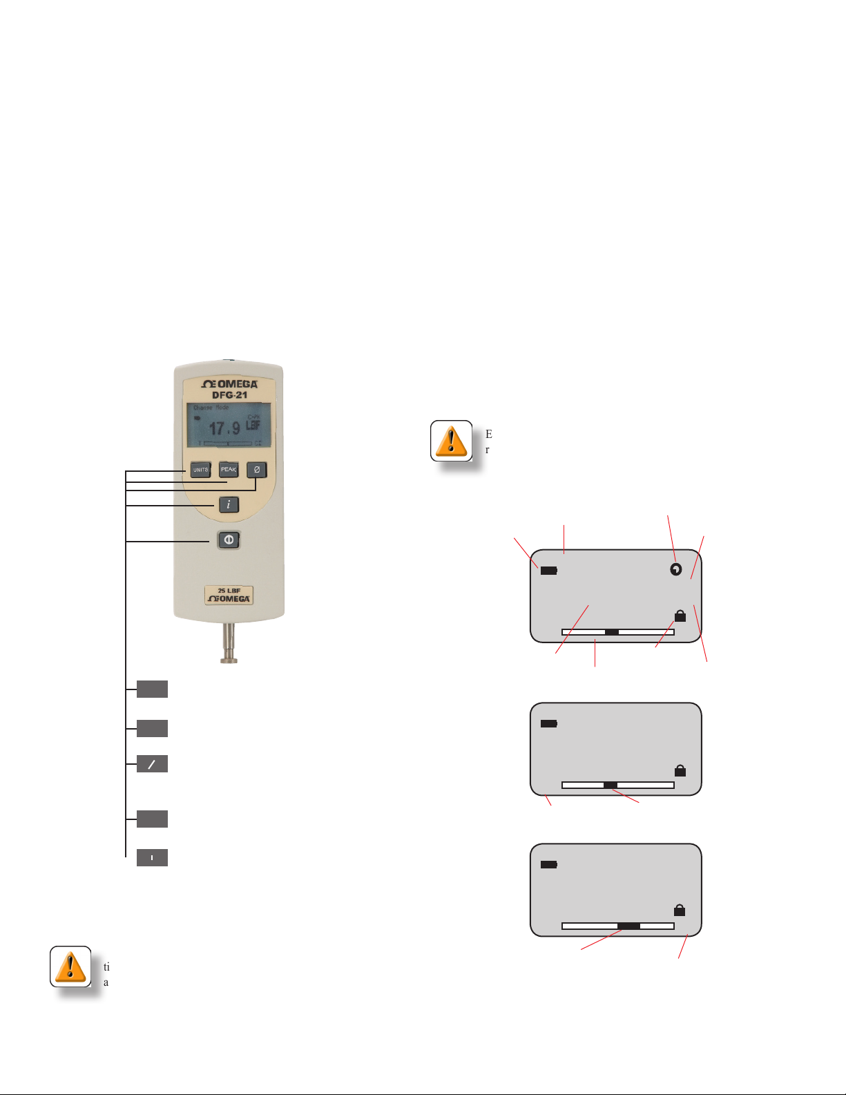
The keypad has an On/Off, Units, Peak, Zero and Info button.
The UNITS button is used to change units of measure. This key may be
disabled using the Units Lock feature.
The PEAK button is used to change mode (Normal or Peak). This key is
also used during gauge setup to enable/disable features.
The ZERO button is used to zero a result or tare. This key is also used in
gauge setup to exit setup and return to the home display.
The INFO (i) button is used to display gauge information including
operating characteristics and gauge setup features.
UNDERSTANDING THE DISPLAY
The display has 8 lines that can display up to 21 characters. Display
contrast is set at the factory and cannot be adjusted. The following icons
may be displayed to show the user features that are active for the gauge:
nBattery Status
nAuto Shutdown is On
nUnits Lock is On
nMode
nUnits of Measure
nMeasured Result Numeric
nMeasured Load Direction Arrows (Tensile or Compression)
Load Bargraph
The bargraph provides a graphical representation of the actual load and
direction of load being applied to the load cell. The bargraph lls from
the centerline. The left side indicates Tensile force. The right side indicates Compressive force.
Sensor Overload
The term “Overload” is displayed if the load cell has a force applied that
is equal or greater than 116% of its rated capacity.
CAUTION
Overloading a load cell can cause permanent damage to the sensor.
Exercise caution to ensure than no force greater than the load cell’s
rated capacity is applied.
Changes measurement units: ozf, gf, lbf, kgf,
Units
N. May be disabled so that units cannot be
changed. (See Units Lock Feature).
Select to view/capture peak measurements.
Peak
Change between Normal and Peak.
Select to Zero measurement or to Tare up to
0
10% of the gauge’s capacity.
Note: When in INFO mode, select the Zero
key to exit and return to Home.
Select to view gauge information and to
i
select gauge operating options. (See Using
INFO Key).
Turn Gauge On or Off.
O
POWER ON/OFF
Turn power On/Off by depressing the power button.
CAUTION
The sensor used in your DFG21 Series gauge is a temperature sensitive device. Before measurements can be made, turn the gauge ON
and allow the instrument to warm-up for at least 7 minutes.
Message Prompt
Battery Status
Change Mode
1.23
q
T
q
Measured result
Measured load bargraph
1.23
q
T
q
Tensile load indicator
11.23
T
Compression load applied to sensor
Auto Shutdown feature is ON
LBF
Units Lock feature is ON
Units of measurement
LBF
Tensile load applied to sensor
LBF
Compression load indicator
Norm
C
Norm
C
Norm
C
q
Mode indicator
q
Page 5
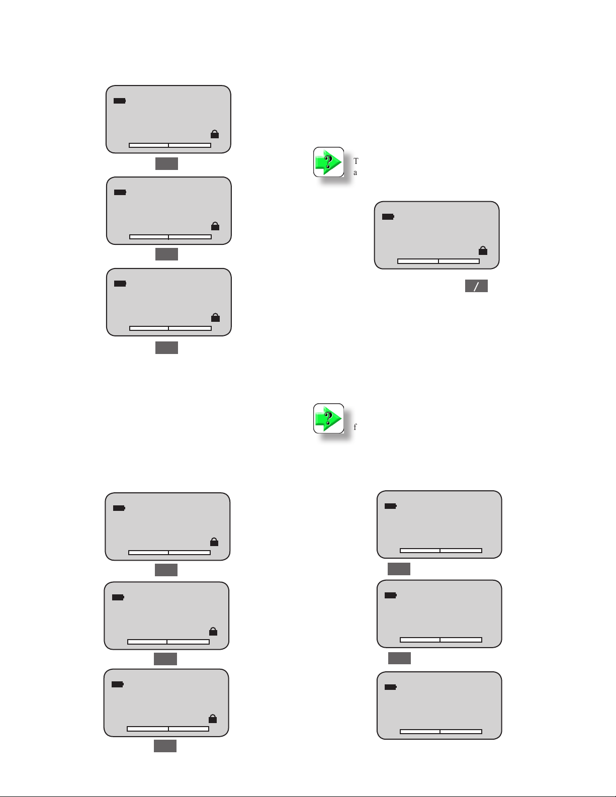
CHANGING MODE
The DFG21 gauge has Normal and Peak modes. Select the PEAK button to change between modes.
Change Mode
Norm
1.23
LBF
ZERO AND TARE
Press the ZERO button to zero a result.
You may tare out up to 10% of the force gauge’s capacity to compensate
for the weight of xtures.
Add the xture to the force gauge.
Press the ZERO button to tare out the xture’s weight.
T
Peak
Change Mode
1.23
q
T
q
Peak
Change Mode
1.23
T
Peak
VIEW PEAK MEASUREMENTS
The DFG21 will display the peak (maximum) load achieved during a
test. There are two methods to view peak results:
1. Place the gauge in Normal mode. Measure the load. Press the
PEAK button once the measurement is completed to view the Peak
result.
C
T-PK
LBF
C
C-PK
LBF
q
C
q
NOTE
The ZERO button is used in gauge setup to exit the setup procedures
and return the gauge to normal measurement operation.
C-PK
0.0
T
LBF
C
0
CHANGING UNITS
Press the UNITS button to change the units of measure. Units are presented in the following order: ozf, gf, lbf, kgf and N.
Force gauges with a rated capacity of 100 lbf (500N, 50 kgf) and higher
do not display ozf or gf equivalents. These capacity force gauges display
units in the following order: lbf, kgf and N.
NOTE
Resolutions cannot be changed. The resolution of the load result is a
function of the load cell being used by the force gauge.
2. Place the gauge in Peak mode prior to making the measurement. Press the PEAK button. Take the measurement and view the
Peak result.
Norm
1.23
q
T
q
Peak
4.56
q
T
q
Peak
7.89
T
Peak
LBF
C
T-PK
LBF
C
C-PK
LBF
q
C
q
Change Units
T
Units
Change Units
T
Units
Change Units
T
1.23
1.23
1.23
Norm
LBF
C
Norm
KGF
C
Norm
N
C
Page 6
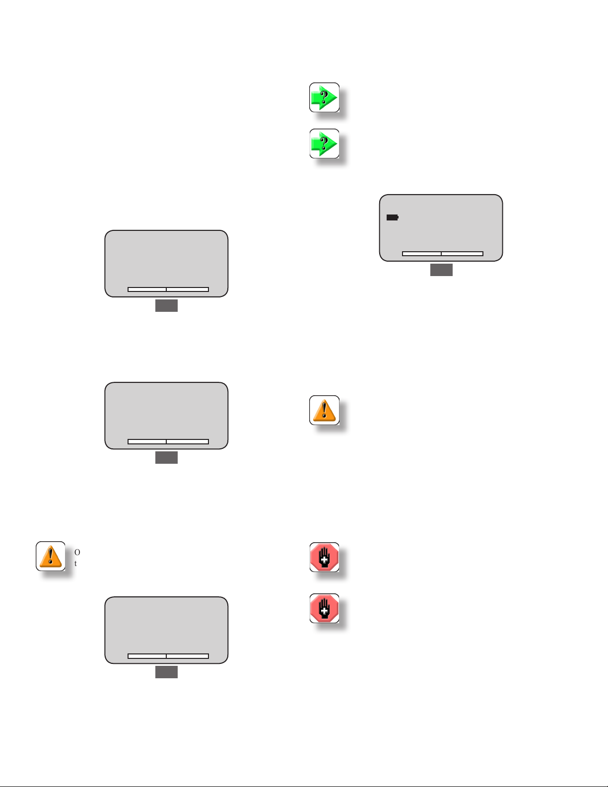
SETTING UP YOUR GAUGE
The DFG21 Series setup is performed using the Setup Menu display.
Individual gauge features are listed. You access the desired feature using “i” button. The “i” button is used to display gauge information and
congurable features in this order when depressed:
1. Capacity
2. Firmware Revision
3. Overload History
4. Battery Life
5. Automatic Shutdown (congure)
6. Units Lock (congure)
7. Display Language (congure)
View Battery Life
Press the “i” button to view the battery life. The gauge will display the
estimate battery hours remaining and the current battery voltage.
NOTE
The DFG21 will display “Replace Batteries” when the battery voltage drops to approximately 7.2Vdc.
NOTE
The DFG21 Series will shutdown automatically when the battery
voltage drops to approximately 6.8Vdc.
View Gauge Capacity
Press the “i” button to view the DFG21 capacity x resolution.
Capacity
200 x 0.2 lbf
100 x 0.1 kgf
1000 x 1 N
T
i
C
View Gauge Firmware Revision
Press the “i” button twice to view the DFG21 model, rmware number,
rmware revision number and revision date.
Firmware
Model DFG21-10
Rev. No. V1.00
Rev. Date dd/mm/yy
T
i
C
View Gauge Overload History
Press the “i” button to view the number of overloads recorded for tension
(Tension) and compression (Comp).
CAUTION
Overloads can damage the load cell. Always take care to observe
the measured load bargraph when taking a measurement. Stop your
measurement when the bargraph is nearly full to avoid overloading
your load cell.
No. of Overloads
No. of Tension 0
No. of Comp. 0
Battery
Est Battery Life
T
100 hrs
9.00 Volts
C
i
CHANGING THE 9VDC BATTERIES
Remove the screws on the back housing. Unplug or plug-in a new 9Vdc
battery to the connector. Close and secure housing. Turn gauge ON to
verify power.
The DFG21 Series is designed to provide over 120 hours of continuous
use with two 9Vdc alkaline batteries.
CAUTION
Make sure power to the DFG21 is OFF.
Use ESD protection when replacing batteries.
USING A BATTERY ELIMINATOR
The DFG21 Series may be operated using the battery eliminator accessory (p/n DFG-UBE) that was supplied with your gauge. When the battery eliminator is used, the internal batteries are by-passed. The battery
eliminator may be plugged into a 115V or 230V power source using one
of the three plug styles that were provided: USA plug, EURO plug, or
UK plug.
WARNING
Use the appropriate plug style that matches your source power outlet.
WARNING
Always use the charger/adapter that was supplied with your force
gauge. Never substitute another type of charger/adapter.
T
i
C
Page 7
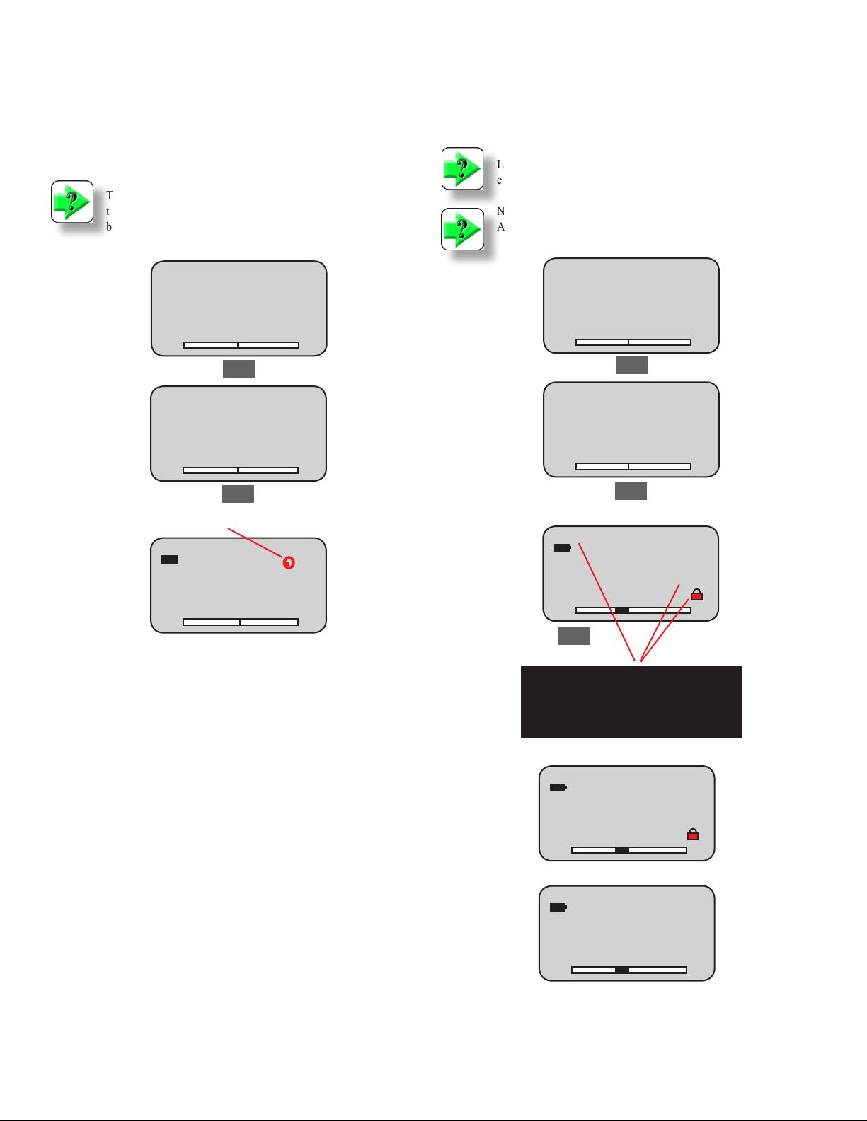
USING AUTO SHUTDOWN
The automatic shutdown feature preserves your battery. If you accidentally leave the power on, the gauge power will shut off automatically
after 30 minutes of inactivity.
Press the “i” button until you display the Auto Shutdown feature. Press
the Peak button to turn the Auto Shutdown feature ON or OFF.
NOTE
The DFG21 Series will shut down automatically whenever the battery voltage drops to approximately 6.8Vdc. You must replace the
batteries or use the Battery Eliminator for continued use.
USING UNITS LOCK
You may lock the units of measure so that the Units key is disabled.
Press “i” button until the Units Lock feature is displayed. Press the
PEAK button to activate/deactivate the Units Lock feature.
NOTE
Locking the Units disables the Units button so that users cannot
change the load units of measure.
NOTE
A pad lock icon displays when the Units Lock feature is ON.
Auto Shutdown
Auto Shutdown Status
OFF
PEAK to Change
INFO to Proceed
T
Peak
Auto Shutdown
Auto Shutdown Status
ON
PEAK to Change
INFO to Proceed
T
Peak
Automatic Shutdown Indicator when On.
1.23
T
C
C
Norm
OZF
C
Units Lock
Units Lock Status
OFF
PEAK to Change
INFO to Proceed
T
Units Lock
Units Lock Status
ON
PEAK to Change
INFO to Proceed
T
Units Locked
q
T
q
Units
Peak
Peak
1.23
C
C
Norm
LBF
C
The Units Locked icon appears when this option is
ON. Pressing the UNITS key will not change the
q
T
q
Shown: Units Lock feature is ON.
q
T
q
Shown: Units Lock feature is OFF.
Note
units of measurement.
1.23
1.23
Norm
LBF
C
Norm
LBF
C
Page 8
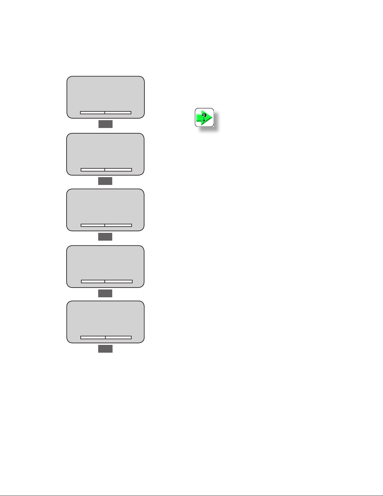
SETUP DISPLAY LANGUAGE
You may change the language used to display information. Textual
information may be displayed in English, Spanish, French, Portuguese,
Chinese or German.
Press “i” button until the Language feature is displayed. Press the PEAK
button to specify and activate the desired display language.
Language
ENGLISH
PEAK to Change
INFO to Proceed
T
Peak
Lenguaje
ESPANOL
PEAK para cambio
INFO para proceder
T
Peak
Langue
FRANCAIS
PEAK pour changer
INFO pour realiser
T
C
C
C
OPERATING YOUR GAUGE
MEASURE LOAD
The DFG21 gauge will measure tensile (pull) and compressive (push)
force. The gauge will display the active measured result.
Measure a tensile load (pull) by attaching the sample to the load cell rod
and pulling in an axial direction.
Measure a compressive load (push) by depressing the sample with the
load cell rod in an axial direction.
NOTE
All loads being applied to the force gauge must be applied in an axial
position, e.g. directly perpendicular to the measurement rod that
extends from the load cell. Applying loads at an angle will produce
incorrect results and may damage the load cell.
Idioma
PORTUGUES
PEAK para mudar
INFO para continuar
T
Sprachauswahl
DEUTSCH
PEAK zum wechseln
INFO zum fortfahren
q
T
T
q
Peak
C
Peak
C
Peak
Page 9
VIEW NORMAL RESULT
Place the DFG21 Series in NORM (normal) mode by pressing Peak
button.
Measure sample and view the result on the display.
Tensile loads are displayed as negative results (-).
Compressive loads are displayed as positive results (no sign).
VIEW PEAK RESULT
Place the gauge into PEAK mode to capture and view the maximum load
measurement result.
Press the Peak button to place gauge in Peak mode. TPK is for tensile
peak results. CPK is for compression peak results.
The gauge will display and hold the peak tensile or compressive result
for your test.
When load is removed, the display indicates zero.
NOTE
You can view the peak load result after using the Normal model.
Do not zero the gauge.
Change the mode to PEAK by pressing the Peak button.
Norm
1.23
q
T
q
Peak
PACKAGING
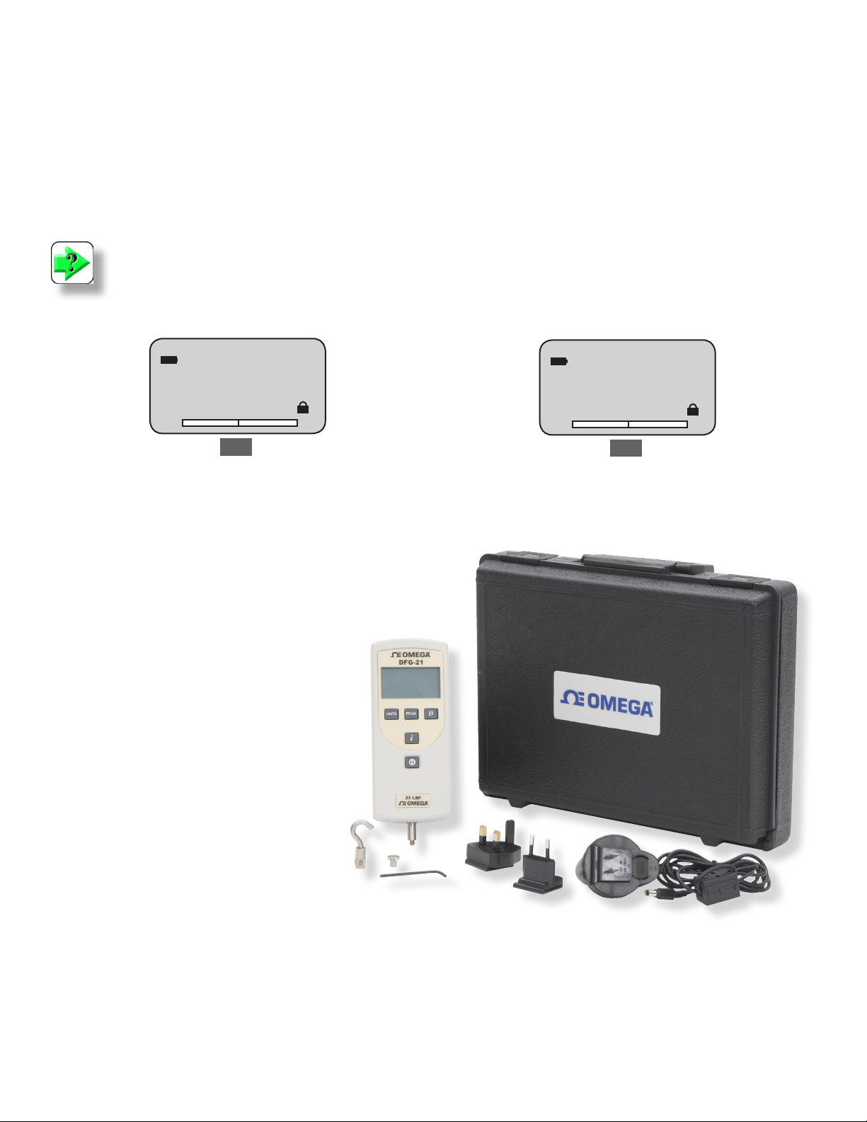
The DFG21 Series is supplied with the following standard accessories:
nFlat Adapter, 100 lbf (p/n DFG-011A) or
nFlat Adapter, 200 lbf (p/n DFG-011B)
nHook Adapter, 50 lbf (p/n DFG-012A) or
nHook Adapter, 100 lbf (p/n DFG-012B) or
nHook Adapter, 200 lbf (p/n DFG-012C)
nDFG21 Battery Eliminator (p/n DFG-UBE)
nDFG21 Carrying Case (p/n DFG-CASE)
nCalibration Certicate with NIST Data
LBF
C
You may save or zero the peak result.
4.56
q
T
q
Peak
T-PK
LBF
C
Requires two (2) 9Vdc Alkaline Batteries (Included).
The DFG21 is supplied with one (1) at adapter and hook.
The accessory supplied is dependent on the DFG21 capacity.
OPTIONAL ACCESSORIES
Description Part No.
Point Adapter (100 lbf) DFG-009A
Point Adapter (200 lbf) DFG-009B
Chisel Adapter (100 lbf) DFG-008A
Chisel Adapter (200 lbf) DFG-008B
Notch Adapter (100 lbf) DFG-010A
Notch Adapter (200 lbf) DFG-010B
Extension Rod, 6-inch (#10-32) DFG-013A
Extension Rod, 6-inch (5/16-18) DFG-013B
Handle Assembly DFG-Handle
Pistol Grip DFG-141
Page 10
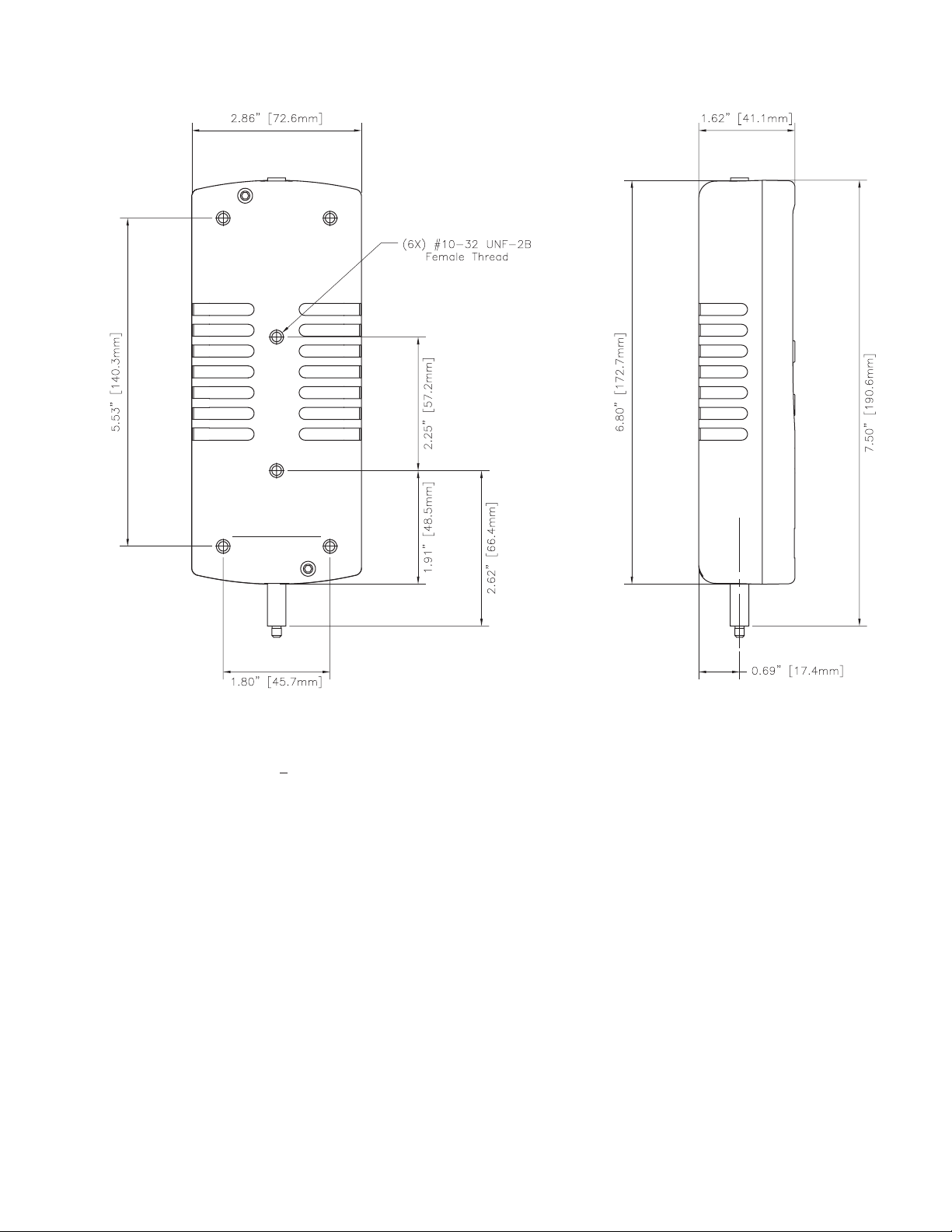
DIMENSIONS
SPECIFICATIONS
Accuracy: +0.5% of Full Scale
Mechanical Overload 150% of Rated Capacity
Tare Capacity 10% of Rated Capacity
Dial Resolution 1000:1
Data Sampling Rate 1000Hz
Operating Temperature 40oF to 110oF (5oC to 45oC)
Instrument Weight 1.5 lbs (0.7 kg)
Shipping Weight 4 lbs (2 kg)
CAPACITY x RESOLUTION
Model Capacity x Resolution
ozf gf lbf kgf N
DFG21-10 160 x 0.1 5000 x 1 10 x 0.01 5 x 0.001 50 x 0.01
DFG21-50 800 x 0.1 25,000 x 10 50 x 0.01 25 x 0.01 250 x 0.1
DFG21-100 1600 x 1 50,000 x 10 100 x 0.1 50 x 0.01 500 x 0.1
DFG21-200 - - 200 x 0.1 100 x 0.1 1000 x 1
CONFORMANCE
The DFG21Series has been accessed against the essential health and
safety requirements of the Low Voltage and the EMC Directives listed
and found to be in compliance.
BS EN 61010-1:2001 Safety Requirement for Electrical Equipment
BS EN 61000-6-3:2001 EMC Generic Emission Standard
BS EN 61000-6-1:2001 EMC Generic Immunity Standard
The DFG21 Series is a RoHS, China RoHS and WEEE compliant
device.
Page 11

WARRANTY/DISCLAIMER
OMEGA ENGINEERING, INC. warrants this unit to be free of defects in materials and workmanship for a period of 13 months
from date of purchase. OMEGA Warranty adds an additional one (1) month grace period to the normal one (1) year product
warranty to cover handling and shipping time. This ensures that OMEGA’s customers received maximum coverage for each
product.
If the units should malfunction, it must be returned to the factory for evaluation. OMEGA’s Customer Service Department will
issue an Authorized Return (RA) number immediately upon phone or written request. Upon examination by OMEGA, if the unit
is found to be defective it will be repaired or replaced at no charge. OMEGA’s WARRANTY does not apply to defects resulting
from any action of the purchaser, including but not limited to mishandling, improper interfacing, operation outside of design limits,
improper repair, or unauthorized modication. This WARRANTY is VOID if the unit shows evidence of having been tampered
with or shows evidence of being damaged as a result of excessive corrosion; or current, heat, moisture or vibration; improper
specication; misapplication; misuse or other operating conditions outside of OMEGA’s control. Components which wear are not
warranted, including but not limited to contact points, fuses, and triacs.
OMEGA is pleased to offer suggestions on the use of its various products. However, OMEGA neither assumes responsibility for any omissions or errors nor assumes liability for any damages that result from the use of its products in accordance with information provided by OMEGA, either verbal or written. OMEGA warrants only that the parts manufac-
tured by it will be as specied and free of defects. OMEGA MAKES NO OTHER WARRANTIES OR REPRESENTATIONS
OF ANY KIND WHATSOEVER, EXPRESSED OR IMPLIED, EXCEPT THAT OF TITLE, AND ALL IMPLIED WARRANTIES
INCLUDING ANY WARRANTY OF MERCHANTABILITY AND FITNESS FOR A PARTICULAR PURPOSE ARE HEREBY DISCLAIMED. LIMITATION OF LIABILITY: The remedies of purchaser set forth herein are exclusive and the total liability
of OMEGA with respect to this order, whether based on contract, warranty, negligence, indemnication, strict liability
or otherwise, shall not exceed the purchase price of the component upon which liability is based. In no event shall
OMEGA be liable for consequential, incidental or special damages.
CONDITIONS: Equipment sold by OMEGA is not intended to be used, nor shall it be used: (1) as a “Basic Component” under 10
CFR 21 (NRC), used in or with any nuclear installation or activity; or (2) in medical applications or used on humans. Should any
Product(s) be used in or with any nuclear installation or activity, medical application, used on humans, or misused in any way,
OMEGA assumes no responsibility as set forth in our basic WARRANTY/DISCLAIMER language, and additionally, purchaser will
indemnify OMEGA and hold OMEGA harmless from any liability or damage whatsoever arising out of the use of the Product(s) in
such a manner.
RETuRN REquESTS/INquIRIES
Direct all warranty and repair requests/inquiries to OMEGA Customer Service Department. BEFORE RETURNING ANY
PRODUCT(S0 TO OMEGA, PURCHASER MUST OBTAIN AN AUTHORIZED RETURN (AR) NUMBER FROM OMEGA’S CUSTOMER SERVICE DEPARTMENT (IN ORDER TO AVOID PROCESSING DELAYS). The assigned AR number should then be
marked on the outside of the return package and on any correspondence.
The purchaser is responsible for shipping charges, freight, insurance and proper packaging to prevent breakage in transit.
FOR WARRANTY RETURNS, please have the following information available BEFORE contacting OMEGA:
1. P.O. number under which the product was PURCHASED,
2. Model and serial number of the product under warranty,
and
3. Repair instructions and/or specic problems relative to the
product.
OMEGA’s policy is to make running changes, not model changes, whenever an improvement is possible. This affords our customers the latest in technology and engineering.
OMEGA is a registered trademark of OMEGA ENGINEERING, INC.
Copyright 2009 OMEGA ENGINEERING, INC. All rights reserved. This document may not be copied, photocopied, reproduced, translated, or reduced
to any electronic medium or machine-readable form, in whole or in part, without prior written consent of OMEGA ENGINEERING, INC.
Part No.
M-4733
February 2009
FOR NON-WARRANTY REPAIRS, consult OMEGA for current repair charges. Have the following information available
BEFORE contacting OMEGA:
1. P.O. number to cover the COST of the repair,
2. Model and serial number of product, and
3. Repair instructions and/or specic problems relative to the
product.
 Loading...