

Page 1
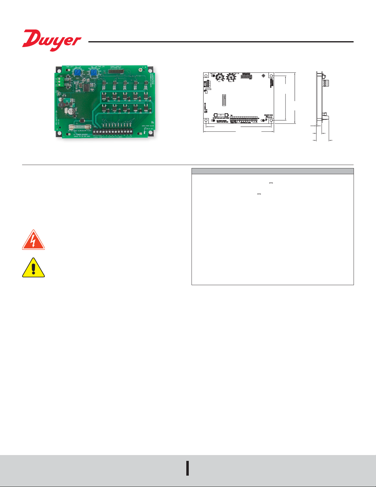
Series DCT500ADC Timer Controller
[30.16]
®
Specications - Installation and Operating Instructions
6-1/4 [158.75]
6-3/4 [171.45]
4-1/4
[107.95]
Bulletin E-98ADC
4-7/8
[123.83]
1/16
[1.59]
1/2
[12.70]
1-3/16
The Series DCT500ADC Timer Controller is a timing system for pulse-jet type
dust collectors or pneumatic conveying systems in either continuous or on-demand
cleaning applications. It is provided with either 4, 6, or 10 channels. The DCT500ADC
was designed for ease of installation in your dust collector system. For installations
requiring fewer channels than available on the board, a shorting plug is provided to
allow selection of the last used channel. Time-on and time-off settings are selected
using two potentiometers. High-limit and low-limit control inputs are provided for use
with on-demand systems. When used in a continuous mode the high-limit input is
jumpered.
Installation
Warning: Always replace the fuse with the proper type and rating.
The fuse is Type 3 AG fast acting 3 Amp @ 250V. DO NOT use slowblow type fuses. Failure to comply with this requirement will void
manufacturer’s warranty.
This equipment is intended to be powered using a recognized Class 2
power supply. If powered from a DC bus a suitable transient protection
device meeting Installation Category II requirements must be used.
Protection provided by the equipment may be impaired if the equipment
is used with accessories not provided or recommended by the
manufacturer, or is used in a manner not specied by the manufacturer.
Power Requirements
The DCT500ADC Series controller is designed for operation with a DC power supply.
The supply voltage must be between 10 VDC and 35 VDC. Exceeding 35 VDC may
damage the unit. The solenoid outputs are driven from the power supply so the
solenoids must be rated for operation at the power supply voltage. The solenoids
are connected as shown in the wiring diagram and must not be connected to any
other external circuit. The solenoid common is the positive (+) lead and is internally
connected to the fused positive (+) supply. The individual outputs are switched to
the negative (-) supply input through an open drain eld effect transistor (FET). The
outputs are protected for inductive yback transients of the solenoids.
Location
The system must be located in an enclosure that meets relevant safety standards and
electrical codes. There are no other special orientation requirements. Mount it using
the four mounting holes in the baseplate. The baseplate back is ush, so no special
spacers are needed to accommodate obstructions except for those imposed by the
location itself.
SPECIFICATIONS
Output Channels: 4, 6, and 10 channels.
Voltage Requirements: 10 to 35 VDC (
Power Consumption: 0.6 W.
Input Power: 106 W @ 35 VDC (
Load: 3A max per channel.
Fuse: Type 3 AG, 3A @ 250 VAC (~).
Ambient Operation Temperature: -40 to 149°F (-40 to 65°C).
Storage Temperature Limits: -40 to 176°F (-40 to 80°C).
Humidity Conditions: 5 to 95% noncondensing.
On Time: 50 to 500 msec.
On Time Accuracy: ±5% of setting.
On Time Repeatability: ±1 msec.
Off Time: 1 to 180 seconds.
Off Time Accuracy: 5% of setting.
Pollution Degree: 2.
Altitude: 6560 ft (2000 m) max.
Environment: Indoor use, must be installed in a weather-proof enclosure for
outside applications.
Weight: 9 oz (255 g).
Agency Approvals: CE.
Connections
The power and solenoid connections are located at the lower edge of the board.
The terminal block is a “Euro” style connector system that clamps the wire within the
connector body. The connector will accept wire sizes from 14 to 22 gages. These
terminals should be torqued to 5 in. lb. The connectors are specied for single
connection but multiple wires may be connected to a single lug provided local codes
allow this and good workmanship practices are followed. When using stranded wire,
make sure that there are no “stray” strands. These may cause system failure or
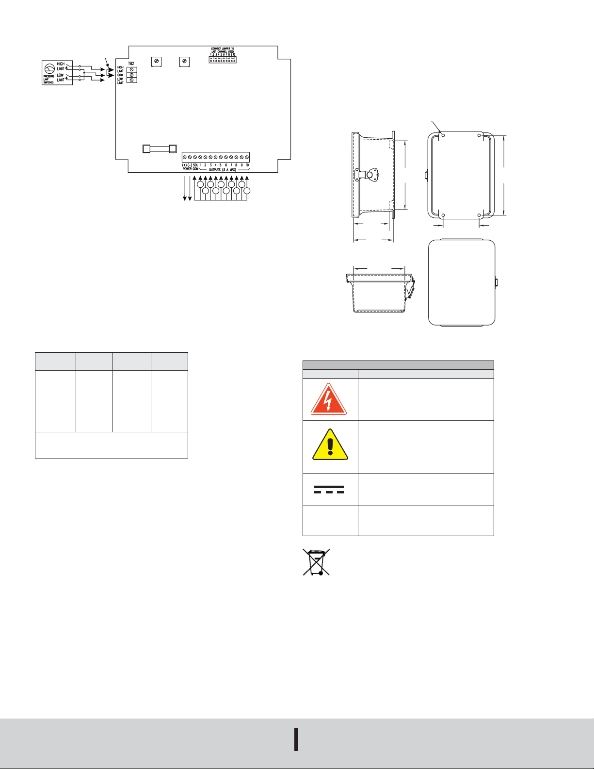
damage. Connect the (+) (-) power to (+) and (-). Connect the solenoids between the
selected output and the solenoid common. Solenoid common and (+) are internally
connected through fuse. Refer to Figure 2-1.
The wire should be stripped to no more than 0.25 in. A strip gauge is provided at
the lower right corner of the board. Longer than this may cause shorts. Switches
connected to the control inputs at the top of the board must be isolated normally open
contacts connected only to the relevant terminal and to the common terminals.
The following subparagraphs describe the external switch connections. Refer to gure
2-1 for switch connection illustration.
).
) max.
DWYER INSTRUMENTS, INC.
P.O. BOX 373 • MICHIGAN CITY, INDIANA 46360, U.S.A.
Phone: 219/879-8000
Fax: 219/872-9057
www.dwyer-inst.com
e-mail: [email protected]
Page 2
SHORT FOR
CONTIUOUS
INPUT
0.31 TYP [7.87]
[225.6]
OPERATION
TIME OFF
TIME ON
TB1
Time Off and Time On Setup
Time off denes the period of time between solenoid activations when no channels are
enabled. This value may be set between 1 second and 180 seconds with a resolution
of 1 second. Time on denes the solenoid on time. The value may be set between 50
msec and 500 msec with a resolution of 10 msec. If adjustments are made while the
system is in operation, the new setting will take effect in the following solenoid cycle.
Do not use excessive force to turn the potentiometers. This will damage the unit. A
factory installed option is available for a time on range of 0.05 to 10 seconds.
4 PLACES
(-)
(+)
SOLENOIDS
POWER
Figure 2-1 Switch Connections
External Limit Switch Connection
The controller may be used with an external pressure limit switch or sensor to provide
demand-cleaning operation. A three pin terminal block provides connection for external
high and low limit switches. A simple on-off system can be established with a single
pressure switch connected to the high limit input. Better control can be achieved with
a high and low limit switch/gage such as the Dwyer Photohelic
switches must be isolated contacts between the high or low limit input and the common
connection. The wiring from the switches must be two or three wires with no other
connections made to these. The common line must not be connected to equipment
ground or protective ground, since these may introduce electrical noise and cause
improper operation or possible damage to the control board. The operation of these
inputs is summarized as follows:
Current
Operation
Hold
Hold or Run
Hold
Hold
Run
Hold
Run
Ø – Transition from open to closed
≠ – Transition closed to open
X – Either open or closed
Low Limit
Switch
Open
X
Ø
Closed
Closed
Closed
≠
High Limit
Switch
Open
Closed
Open
Ø
≠
Ø
Open
Next
Operation
Hold
Run
Hold
Run
Run
Run
Hold
®
pressure gage. The
4.00
[101.6]
4.45
[113.0]
5.74
[145.8]
Weatherproof Enclosure Option
EXPLANATION OF SYMBOLS
Symbol Description
Caution: Risk of electric shock
Caution: Risk of danger, refer to user’s
manual for further information
7.73
[196.3]
4.00 TYP
[101.6]
8.88
Operating Modes
Continuous Cycle Mode
The DCT500ADC has two operating modes available for different applications.
Starting with the most basic mode, it is capable of operating in a continuous cleaning
cycle. This can be initiated by placing a jumper between the high limit input and the
common connection. Two setup parameters control operation: time off, time on. Time
on and time off specically deal with the solenoid on time and the time interval between
the end of the on pulse and the start of the next.
Demand Mode
Demand mode operation can be congured using the high limit and low limit inputs. A
simple on-off system can be setup with a single pressure switch connected to the high
limit input. Better control can be achieved with a high and low limit switch set such as
is provided in the Dwyer Photohelic
on and time off may be programmed to dene the cleaning cycle. When the cycle is
completed, the controller will continue the cycle until the last channel is pulsed. The
next cleaning cycle will always start on channel 1. A factory installed option is available
that will not clean to the end of a cycle, but rather stop where the cleaning cycle ended.
The next demand for cleaning will start where the last cleaning cycle left off.
System Setup
Last Channel Selection
A jumper connector is provided to select the last channel used. Place the jumper on
the two pins corresponding to the last channel used in the installation.
®
pressure gage. In this on-demand mode, time
Printed in U.S.A. 2/19 FR# 443180-10 Rev. 2©Copyright 2019 Dwyer Instruments, Inc.
DWYER INSTRUMENTS, INC.
P.O. BOX 373 • MICHIGAN CITY, INDIANA 46360, U.S.A.
Direct current
Alternating current
~
This symbol indicates waste electrical products should not be disposed
of with household waste. Please recycle where facilities exist. Check with
your Local Authority or retailer for recycling advice.
Agency Approvals and Test Standards:
CE: IEC 61000-4-2: 2001
IEC 61000-4-3: 2006
IEC 61000-4-4: 2004
IEC 61000-4-5: 2005
IEC 61000-4-6: 2006
CENELEC EN 55022: 2007
FCC Part 15 CFR Title 47: 2007
ICES-003: 2004 Digital Apparatus (Industry Canada)
ANSI 63.4-2003
CENELEC EN 61326-1: 2006
2004/108/EC EMC Directive
Phone: 219/879-8000
Fax: 219/872-9057
www.dwyer-inst.com
e-mail: [email protected]
 Loading...