

Page 1
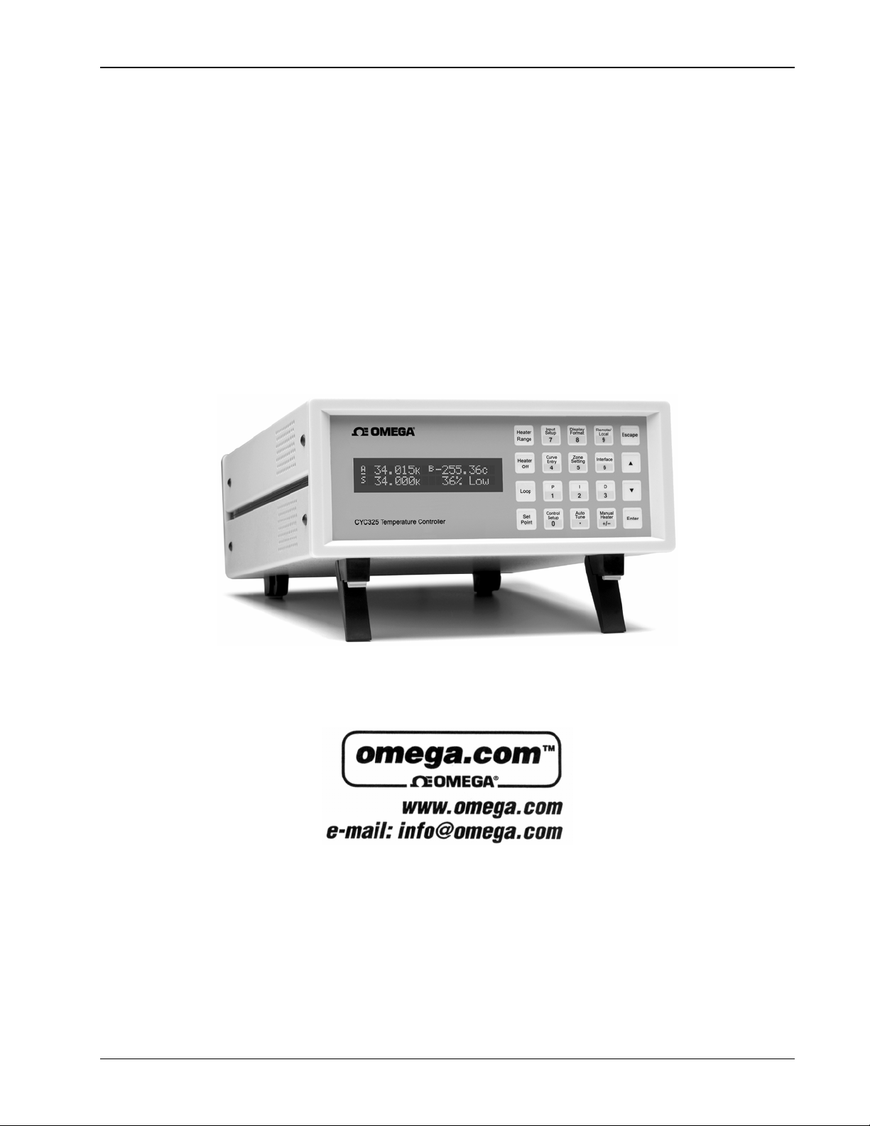
User’s Manual
CYC325, CYC325-T1, CYC325-T2
Cryogenic Temperature Controller
Rev. 2.0 M-4448/0307 09 March 2007
Page 2
Omega Model CYC325 Temperature Controller User’s Manual
B
Page 3

Omega Model CYC325 Temperature Controller User’s Manual
Electromagnetic Compatibility (EMC) for the Model CYC325 Temperature Controller
Electromagnetic Compatibility (EMC) of electronic equipment is a growing concern worldwide. Emissions of
and immunity to electromagnetic interference is now part of the design and manufacture of most electronics. To
qualify for the CE Mark, the Model CYC325 meets or exceeds the requirements of the European EMC
Directive 89/336/EEC as a CLASS A product. A Class A product is allowed to radiate more RF than a Class B
product and must include the following warning:
WARNING: This is a Class A product. In a domestic environment, this product may cause radio
The instrument was tested under normal operating conditions with sensor and interface cables attached. If the
installation and operating instructions in the User’s Manual are followed, there should be no degradation in
EMC performance.
This instrument is not intended for use in close proximity to RF Transmitters such as two-way radios and cell
phones. Exposure to RF interference greater than that found in a typical laboratory environment may disturb the
sensitive measurement circuitry of the instrument.
Pay special attention to instrument cabling. Improperly installed cabling may defeat even the best EMC
protection. For the best performance from any precision instrument, follow the grounding and shielding
instructions in the User’s Manual. In addition, the installer of the Model CYC325 should consider the
following:
• Shield measurement and computer interface cables.
• Leave no unused or unterminated cables attached to the instrument.
• Make cable runs as short and direct as possible. Higher radiated emissions is possible with long cables.
• Do not tightly bundle cables that carry different types of signals.
interference in which case the user may be required to take adequate measures.
C
Page 4

Omega Model CYC325 Temperature Controller User’s Manual
This Page Intentionally Left Blank
B
Page 5

Omega Model CYC325 Temperature Controller User’s Manual
TABLE OF CONTENTS
Chapter/Section Title Page
1 INTRODUCTION ....................................................................................................................................................1-1
1.0 PRODUCT DESCRIPTION ...............................................................................................................1-1
1.1 SENSOR SELECTION...................................................................................................................... 1-4
1.2 SPECIFICATIONS.............................................................................................................................1-6
1.3 SAFETY SUMMARY.........................................................................................................................1-8
1.4 SAFETY SYMBOLS.......................................................................................................................... 1-9
2 COOLING SYSTEM DESIGN................................................................................................................................. 2-1
2.0 GENERAL ......................................................................................................................................... 2-1
2.1 TEMPERATURE SENSOR SELECTION.......................................................................................... 2-1
2.1.1 Temperature Range.......................................................................................................................2-1
2.1.2 Sensor Sensitivity ..........................................................................................................................2-1
2.1.3 Environmental Conditions..............................................................................................................2-1
2.1.4 Measurement Accuracy................................................................................................................. 2-2
2.1.5 Sensor Package.............................................................................................................................2-2
2.2 CALIBRATED SENSORS .................................................................................................................2-2
2.2.1 Traditional Calibration....................................................................................................................2-2
2.2.2 SoftCal™........................................................................................................................................2-2
2.2.3 Standard Curves............................................................................................................................2-3
2.2.4 CalCurve™ ....................................................................................................................................2-4
2.3 SENSOR INSTALLATION.................................................................................................................2-4
2.3.1 Mounting Materials......................................................................................................................... 2-4
2.3.2 Sensor Location............................................................................................................................. 2-4
2.3.3 Thermal Conductivity ..................................................................................................................... 2-4
2.3.4 Contact Area.................................................................................................................................. 2-4
2.3.5 Contact Pressure........................................................................................................................... 2-5
2.3.6 Lead Wire.......................................................................................................................................2-5
2.3.7 Lead Soldering...............................................................................................................................2-6
2.3.8 Heat Sinking Leads........................................................................................................................ 2-6
2.3.9 Thermal Radiation........................................................................................................
2.4 HEATER SELECTION AND INSTALLATION.................................................................................... 2-6
2.4.1 Heater Resistance and Power .......................................................................................................2-6
2.4.2 Heater Location..............................................................................................................................2-7
2.4.3 Heater Types .................................................................................................................................2-7
2.4.4 Heater Wiring................................................................................................................................. 2-7
2.5 CONSIDERATIONS FOR GOOD CONTROL................................................................................... 2-7
2.5.1 Thermal Conductivity ..................................................................................................................... 2-7
2.5.2 Thermal Lag...................................................................................................................................2-7
2.5.3 Two-Sensor Approach ................................................................................................................... 2-7
2.5.4 Thermal Mass................................................................................................................................2-8
2.5.5 System Nonlinearity....................................................................................................................... 2-8
2.6 PID CONTROL.................................................................................................................................. 2-8
2.6.1 Proportional (P)..............................................................................................................................2-8
2.6.2 Integral (I).......................................................................................................................................2-9
2.6.3 Derivative (D)................................................................................................................................. 2-9
2.6.4 Manual Heater Power (MHP) Output............................................................................................. 2-9
2.7 MANUAL TUNING...........................................................................................................................2-11
2.7.1 Setting Heater Range ..................................................................................................................2-11
2.7.2 Tuning Proportional...................................................................................................................... 2-11
2.7.3 Tuning Integral............................................................................................................................. 2-12
2.7.4 Tuning Derivative......................................................................................................................... 2-12
2.8 AUTOTUNING................................................................................................................................. 2-12
2.9 ZONE TUNING................................................................................................................................ 2-13
..................2-6
Table of Contents i
Page 6

Omega Model CYC325 Temperature Controller User’s Manual
TABLE OF CONTENTS (Continued)
Chapter/Section Title Page
3 INSTALLATION......................................................................................................................................................3-1
3.0 GENERAL .........................................................................................................................................3-1
3.1 INSPECTION AND UNPACKING......................................................................................................3-1
3.2 REAR PANEL DEFINITION...............................................................................................................3-2
3.3 LINE INPUT ASSEMBLY...................................................................................................................3-3
3.3.1 Line Voltage...................................................................................................................................3-3
3.3.2 Line Fuse and Fuse Holder............................................................................................................3-3
3.3.3 Power Cord.................................................................................................................................... 3-3
3.3.4 Power Switch.................................................................................................................................3-3
3.4 DIODE/RESISTOR SENSOR INPUTS.............................................................................................. 3-4
3.4.1 Sensor Input Connector and Pinout...............................................................................................3-4
3.4.2 Sensor Lead Cable ........................................................................................................................3-4
3.4.3 Grounding and Shielding Sensor Leads.........................................................................................3-5
3.4.4 Sensor Polarity...............................................................................................................................3-5
3.4.5 Four-Lead Sensor Measurement ...................................................................................................3-5
3.4.6 Two-Lead Sensor Measurement....................................................................................................3-5
3.4.7 Lowering Measurement Noise........................................................................................................3-6
3.5 THERMOCOUPLE SENSOR INPUTS..............................................................................................3-6
3.5.1 Sensor Input Terminals..................................................................................................................3-6
3.5.2 Thermocouple Installation..............................................................................................................3-7
3.5.3 Grounding and Shielding................................................................................................................3-7
3.6 HEATER OUTPUT SETUP ...............................................................................................................3-7
3.6.1 Loop 1 Output ................................................................................................................................3-7
3.6.2 Loop 1 Heater Output Connector...................................................................................................3-7
3.6.3 Loop 1 Heater Output Wiring .........................................................................................................3-7
3.6.4 Loop 1 Heater Output Noise ..........................................................................................................3-8
3.6.5 Loop 2 Output ................................................................................................................................3-8
3.6.6 Loop 2 Output Resistance.................................................................................................
.............3-8
3.6.7 Loop 2 Output Connector...............................................................................................................3-8
3.6.8 Loop 2 Heater Protection ...............................................................................................................3-8
3.6.9 Boosting the Output Power............................................................................................................3-8
3.7 INITIAL SETUP AND SYSTEM CHECKOUT PROCEDURE ............................................................3-9
4 OPERATION...........................................................................................................................................................4-1
4.0 GENERAL .........................................................................................................................................4-1
4.1 FRONT PANEL DESCRIPTION........................................................................................................4-1
4.1.1 Keypad Definitions.........................................................................................................................4-1
4.1.2 Annunciators..................................................................................................................................4-2
4.1.3 General Keypad Operation ............................................................................................................4-2
4.1.4 Display Definition ........................................................................................................................... 4-3
4.2 TURNING POWER ON .....................................................................................................................4-4
4.3 DISPLAY FORMAT AND SOURCE (UNITS) SELECTION...............................................................4-4
4.4 INPUT SETUP...................................................................................................................................4-6
4.4.1 Diode Sensor Input Setup – 10 µA Excitation Current...................................................................4-6
4.4.2 Diode Sensor Input Setup – 1 mA Excitation Current ....................................................................4-6
4.4.3 Resistor Sensor Input Setup ..........................................................................................................4-7
4.4.3.1 Thermal EMF Compensation......................................................................................................4-8
4.4.4 Thermocouple Sensor Input Setup.................................................................................................4-8
4.4.4.1 Room-Temperature Compensation ............................................................................................4-9
4.4.4.2 Room-Temperature Calibration Procedure.................................................................................4-9
4.5 CURVE SELECTION.......................................................................................................................4-10
4.5.1 Diode Sensor Curve Selection.....................................................................................................4-11
4.5.2 Resistor Sensor Curve Selection ................................................................................................. 4-11
4.5.3 Thermocouple Sensor Curve Selection........................................................................................4-11
4.5.4 Filter.............................................................................................................................................4-11
ii Table of Contents
Page 7

Omega Model CYC325 Temperature Controller User’s Manual
TABLE OF CONTENTS (Continued)
Chapter/Section Title Page
4.6 TEMPERATURE CONTROL........................................................................................................... 4-12
4.6.1 Control Loops............................................................................................................................... 4-12
4.6.2 Control Modes.............................................................................................................................. 4-13
4.6.3 Tuning Modes.............................................................................................................................. 4-13
4.7 CONTROL SETUP.......................................................................................................................... 4-14
4.8 MANUAL TUNING...........................................................................................................................4-15
4.8.1 Manually Setting Proportional (P) ................................................................................................4-15
4.8.2 Manually Setting Integral (I).........................................................................................................4-16
4.8.3 Manually Setting Derivative (D)....................................................................................................4-16
4.8.4 Setting Manual Heater Power (MHP) Output...............................................................................4-17
4.9 AUTOTUNE (Closed-Loop PID Control).......................................................................................... 4-17
4.10 ZONE SETTINGS (Closed-Loop Control Mode).............................................................................. 4-18
4.11 SETPOINT.......................................................................................................................................4-21
4.12 RAMP..............................................................................................................................................4-22
4.13 HEATER RANGE AND HEATER OFF............................................................................................ 4-23
4.14 HEATER RESISTANCE SETTING..................................................................................................4-23
4.15 LOCKING AND UNLOCKING THE KEYPAD.................................................................................. 4-24
4.16 REMOTE/LOCAL ............................................................................................................................4-24
4.17 INTERFACE....................................................................................................................................4-24
4.18 DEFAULT VALUES......................................................................................................................... 4-25
5 ADVANCED OPERATION ..................................................................................................................................... 5-1
5.0 GENERAL ......................................................................................................................................... 5-1
5.1 CURVE NUMBERS AND STORAGE................................................................................................ 5-1
5.1.1 Curve Header Parameters............................................................................................................. 5-1
5.1.2 Curve Breakpoints .........................................................................................................................5-1
5.2 FRONT PANEL CURVE ENTRY OPERATIONS ..............................................................................5-3
5.2.1 Edit Curve...............................................................................................................
.......................5-3
5.2.1.1 Thermocouple Curve Considerations.........................................................................................5-5
5.2.2 Erase Curve................................................................................................................................... 5-5
5.2.3 Copy Curve.................................................................................................................................... 5-6
5.3 SOFTCAL™ ...................................................................................................................................... 5-6
5.3.1 SoftCal With Silicon Diode Sensors............................................................................................... 5-7
5.3.2 SoftCal Accuracy With Silicon Diode Sensors ...............................................................................5-7
5.3.3 SoftCal With Platinum Sensors...................................................................................................... 5-8
5.3.4 SoftCal Accuracy With Platinum Sensors...................................................................................... 5-8
5.3.5 SoftCal Calibration Curve Creation................................................................................................ 5-9
6 COMPUTER INTERFACE OPERATION................................................................................................................ 6-1
6.0 GENERAL ......................................................................................................................................... 6-1
6.1 IEEE-488 INTERFACE......................................................................................................................6-1
6.1.1 IEEE-488 Interface Parameters..................................................................................................... 6-1
6.1.2 Remote/Local Operation................................................................................................................6-2
6.1.3 IEEE-488 Command Structure....................................................................................................... 6-2
6.1.3.1 Bus Control Commands ............................................................................................................. 6-2
6.1.3.2 Common Commands ................................................................................................................. 6-3
6.1.3.3 Device Specific Commands........................................................................................................6-3
6.1.3.4 Message Strings.........................................................................................................................6-3
6.1.4 Status System................................................................................................................................ 6-3
6.1.4.1 Overview .................................................................................................................................... 6-3
6.1.4.2 Status Register Sets...................................................................................................................6-6
6.1.4.3 Status Byte and Service Request (SRQ)....................................................................................6-7
6.1.5 IEEE Interface Example Programs .............................................................................................. 6-10
6.1.5.1 IEEE-488 Interface Board Installation for Visual Basic Program .............................................. 6-10
6.1.5.2 Visual Basic IEEE-488 Interface Program Setup...................................................................... 6-10
6.1.5.3 Program Operation................................................................................................................... 6-14
6.1.6 Troubleshooting........................................................................................................................... 6-14
Table of Contents iii
Page 8

Omega Model CYC325 Temperature Controller User’s Manual
TABLE OF CONTENTS (Continued)
Chapter/Section Title Page
6.2 SERIAL INTERFACE OVERVIEW .................................................................................................. 6-15
6.2.1 Physical Connection.....................................................................................................................6-15
6.2.2 Hardware Support........................................................................................................................6-15
6.2.3 Character Format.........................................................................................................................6-16
6.2.4 Message Strings .......................................................................................................................... 6-16
6.2.5 Message Flow Control .................................................................................................................6-16
6.2.6 Changing Baud Rate....................................................................................................................6-17
6.2.7 Serial Interface Example Program ............................................................................................... 6-17
6.2.7.1 Visual Basic Serial Interface Program Setup............................................................................6-17
6.2.7.2 Program Operation................................................................................................................... 6-20
6.2.8 Troubleshooting ...........................................................................................................................6-20
6.3 COMMAND SUMMARY ..................................................................................................................6-21
6.3.1 Interface Commands (Alphabetical Listing).................................................................................. 6-23
7 OPTIONS AND ACCESSORIES............................................................................................................................7-1
7.0 GENERAL .........................................................................................................................................7-1
7.1 MODELS ...........................................................................................................................................7-1
7.2 OPTIONS ..........................................................................................................................................7-1
7.3 ACCESSORIES.................................................................................................................................7-2
7.4 MODEL 3003 HEATER OUTPUT CONDITIONER............................................................................7-4
8 SERVICE ................................................................................................................................................................ 8-1
8.0 GENERAL .........................................................................................................................................8-1
8.1 CONTACTING OMEGA ....................................................................................................................8-1
8.2 RETURNING PRODUCTS TO OMEGA............................................................................................ 8-1
8.3 FUSE DRAWER................................................................................................................................8-2
8.4 LINE VOLTAGE SELECTION ...........................................................................................................8-2
8.5 FUSE REPLACEMENT.....................................................................................................................8-3
8.6 ELECTROSTATIC DISCHARGE.......................................................................................................8-3
8.6.1 Identification of Electrostatic Discharge Sensitive Components..................................................... 8-3
8.6.2 Handling Electrostatic Discharge Sensitive Components............................................................... 8-3
8.7 REAR PANEL CONNECTOR DEFINITIONS....................................................................................8-4
8.7.1 Serial Interface Cable Wiring .........................................................................................................8-6
8.7.2 IEEE-488 Interface Connector .......................................................................................................8-7
8.8 TOP OF ENCLOSURE REMOVE AND REPLACE PROCEDURE....................................................8-8
8.9 FIRMWARE AND NOVRAM REPLACEMENT..................................................................................8-8
8.10 JUMPERS .........................................................................................................................................8-9
8.11 ERROR MESSAGES.........................................................................................................................8-9
8.12 CALIBRATION PROCEDURE.........................................................................................................8-11
8.12.1 Equipment Required for Calibration.............................................................................................8-11
8.12.2 Diode/Resistor Sensor Input Calibration......................................................................................8-12
8.12.2.1 Sensor Input Calibration Setup and Serial Communication Verification...................................8-12
8.12.2.2 10 µA Current Source Calibration and 1 mA Current Source Verification.................................8-12
8.12.2.3 Diode Input Ranges Calibration................................................................................................8-13
8.12.2.4 Resistive Input Ranges Calibration...........................................................................................8-14
8.12.3 Diode Sensor Input Calibration – 1 mA Excitation Current...........................................................8-15
8.12.4 Thermocouple Sensor Input Calibration.......................................................................................8-15
8.12.4.1 Sensor Input Calibration Setup.................................................................................................8-15
8.12.4.2 Thermocouple Input Ranges Calibration .................................................................................. 8-15
8.12.5 Loop 2 Heater Calibration ............................................................................................................8-16
8.12.5.1 Loop 2 Voltage Output Calibration............................................................................................8-16
8.12.6 Calibration Specific Interface Commands....................................................................................8-17
APPENDIX A – GLOSSARY OF TERMINOLOGY....................................................................................................... A-1
APPENDIX B – TEMPERATURE SCALES.................................................................................................................. B-1
APPENDIX C – HANDLING OF LIQUID HELIUM AND NITROGEN........................................................................... C-1
APPENDIX D – CURVE TABLES................................................................................................................................. D-1
iv Table of Contents
Page 9

Omega Model CYC325 Temperature Controller User’s Manual
LIST OF ILLUSTRATIONS
Figure No. Title Page
1-1 Model CYC325 Front View...........................................................................................................................1-1
1-2 Model CYC325 Rear Panel Connections..................................................................................................... 1-2
2-1 Silicon Diode Sensor Calibrations and CalCurve ......................................................................................... 2-3
2-2 Typical Sensor Installation In A Mechanical Refrigerator............................................................................. 2-5
2-3 Examples of PID Control............................................................................................................................ 2-10
3-1 Model CYC325 Rear Panel.......................................................................................................................... 3-2
3-2 Line Input Assembly..................................................................................................................................... 3-3
3-3 Diode/Resistor Input Connector ................................................................................................................... 3-4
3-4 Thermocouple Input Definition and Common Connector Polarities.............................................................. 3-6
4-1 Model CYC325 Front Panel .........................................................................................................................4-1
4-2 Display Definition .........................................................................................................................................4-3
4-3 Display Format Definition............................................................................................................................. 4-4
4-4 Record of Zone Settings............................................................................................................................. 4-20
5-1 SoftCal Temperature Ranges for Silicon Diode Sensors..............................................................................5-7
5-2 SoftCal Temperature Ranges for Platinum Sensors.....................................................................................5-8
6-1 Model CYC325 Status System.....................................................................................................................6-4
6-2 Standard Event Status Register...................................................................................................................6-6
6-3 Operation Event Register............................................................................................................................. 6-7
6-4 Status Byte Register and Service Request Enable Register........................................................................ 6-8
6-5 GPIB Setting Configuration........................................................................................................................ 6-11
6-6 DEV 12 Device Template Configuration..................................................................................................... 6-11
7-1 Model CYC325 Sensor and Heater Cable Assembly...................................................................................7-4
7-2 Model 3003 Heater Output Conditioner ........................................................................................................ 7-4
7-3 Model RM-1/2 Rack-Mount Kit..................................................................................................................... 7-5
7-4 Model RM-2 Dual Rack-Mount Kit.............................................................................................
8-1 Fuse Drawer.................................................................................................................................................8-2
8-2 Power Fuse Access......................................................................................................................................8-2
8-3 Sensor INPUT A and B Connector Details................................................................................................... 8-4
8-4 HEATER OUTPUT Connector Details..........................................................................................................8-4
8-5 RELAYS and ANALOG OUTPUT Terminal Block........................................................................................ 8-5
8-6 RS-232 Connector Details............................................................................................................................8-5
8-7 IEEE-488 Rear Panel Connector Details......................................................................................................8-7
8-8 Location of Internal Components ...............................................................................................................8-10
B-1 Temperature Scale Comparison ..................................................................................................................B-1
C-1 Typical Cryogenic Storage Dewar................................................................................................................C-1
...................7-6
Table of Contents v
Page 10

Omega Model CYC325 Temperature Controller User’s Manual
LIST OF TABLES
Table No. Title Page
1-1 Sensor Temperature Range.........................................................................................................................1-4
1-2 Typical Sensor Performance........................................................................................................................1-5
4-1 Sensor Input Types......................................................................................................................................4-6
4-2 Sensor Curves............................................................................................................................................4-10
4-3 Comparison of Control Loops 1 and 2........................................................................................................4-13
4-4 Default Values............................................................................................................................................4-26
5-1 Curve Header Parameters............................................................................................................................5-2
5-2 Recommended Curve Parameters...............................................................................................................5-2
6-1 Binary Weighting of an 8-Bit Register...........................................................................................................6-5
6-2 Register Clear Methods................................................................................................................................6-5
6-3 Programming Example to Generate an SRQ ...............................................................................................6-9
6-4 IEEE-488 Interface Program Control Properties.........................................................................................6-12
6-5 Visual Basic IEEE-488 Interface Program..................................................................................................6-13
6-6 Serial Interface Specifications....................................................................................................................6-15
6-7 Serial Interface Program Control Properties............................................................................................... 6-18
6-8 Visual Basic Serial Interface Program........................................................................................................6-19
6-9 Command Summary ..................................................................................................................................6-22
8-1 Calibration Table for Diode Ranges ...........................................................................................................8-13
8-2 Calibration Table for Resistive Ranges ......................................................................................................8-15
8-3 Calibration Table for Thermocouple Ranges.............................................................................................. 8-16
B-1 Temperature Conversion Table....................................................................................................................B-2
C-1 Comparison of Liquid Helium and Liquid Nitrogen ...................................................................................... C-1
D-1 CY7 Silicon Diode Curve (Curve 10)........................................................................................................... D-1
D-2 CY670 Silicon Diode Curve..................................................................................................
D-3 DT-500 Series Silicon Diode Curves........................................................................................................... D-2
D-4 PT-100/-1000 Platinum RTD Curves........................................................................................................... D-3
D-5 RX-102A Rox™ Curve ................................................................................................................................ D-4
D-6 RX-202A Rox™ Curve ................................................................................................................................ D-5
D-7 Type K Thermocouple Curve....................................................................................................................... D-6
D-8 Type E Thermocouple Curve....................................................................................................................... D-7
D-9 Type T Thermocouple Curve....................................................................................................................... D-8
D-10 Chromel-AuFe 0.03% Thermocouple Curve................................................................................................ D-9
D-11 Chromel-AuFe 0.07% Thermocouple Curve...............................................................................................D-10
....................... D-2
vi Table of Contents
Page 11
Omega Model CYC325 Temperature Controller User’s Manual
CHAPTER 1
INTRODUCTION
1.0 PRODUCT DESCRIPTION
The Model CYC325 dual-channel temperature controller is capable of supporting nearly any diode, RTD, or
thermocouple temperature sensor. Two independent PID control loops with heater outputs of 25 W and 2 W are
configured to drive either a 50 Ω or 25 Ω load for optimal cryocooler control flexibility. Designed with ease of use,
functionality, and value in mind, the Model CYC325 is ideal for general-purpose laboratory and industrial temperature
measurement and control applications.
Sensor Inputs
The Model CYC325 temperature controller features two inputs with a high-resolution 24-bit analog-to-digital converter
and separate current sources for each input. Constant current excitation allows temperature to be measured and
controlled down to 2.0 K using appropriate Cernox™ RTDs or down to 1.4 K using silicon diodes. Thermocouples allow
for temperature measurement and control above 1,500 K. Sensors are optically isolated from other instrument functions
for quiet and repeatable sensor measurements. The Model CYC325 also uses current reversal to eliminate thermal EMF
errors in resistance sensors. Sensor data from each input is updated up to ten times per second, with display outputs twice
each second. Standard temperature response curves for silicon diodes, platinum RTDs, ruthenium oxide RTDs, and many
thermocouples are included. Up to fifteen 200-point CalCurves
be stored into non-volatile memory. A built-in SoftCal
®
platinum RTDs for storage as user curves. The curve handler software program allows sensor curves to be easily loaded
and manipulated.
Sensor inputs for the Model CYC325 are factory configured and compatible with either diodes/RTDs or thermocouple
sensors. Your choice of two diode/ RTD inputs, one diode/RTD input and one thermocouple input, or two thermocouple
inputs must be specified at time of order and cannot be reconfigured in the field. Software selects appropriate excitation
current and signal gain levels when the sensor type is entered via the instrument front panel.
®
(for calibrated temperature sensors) or user curves can
algorithm can be used to generate curves for silicon diodes and
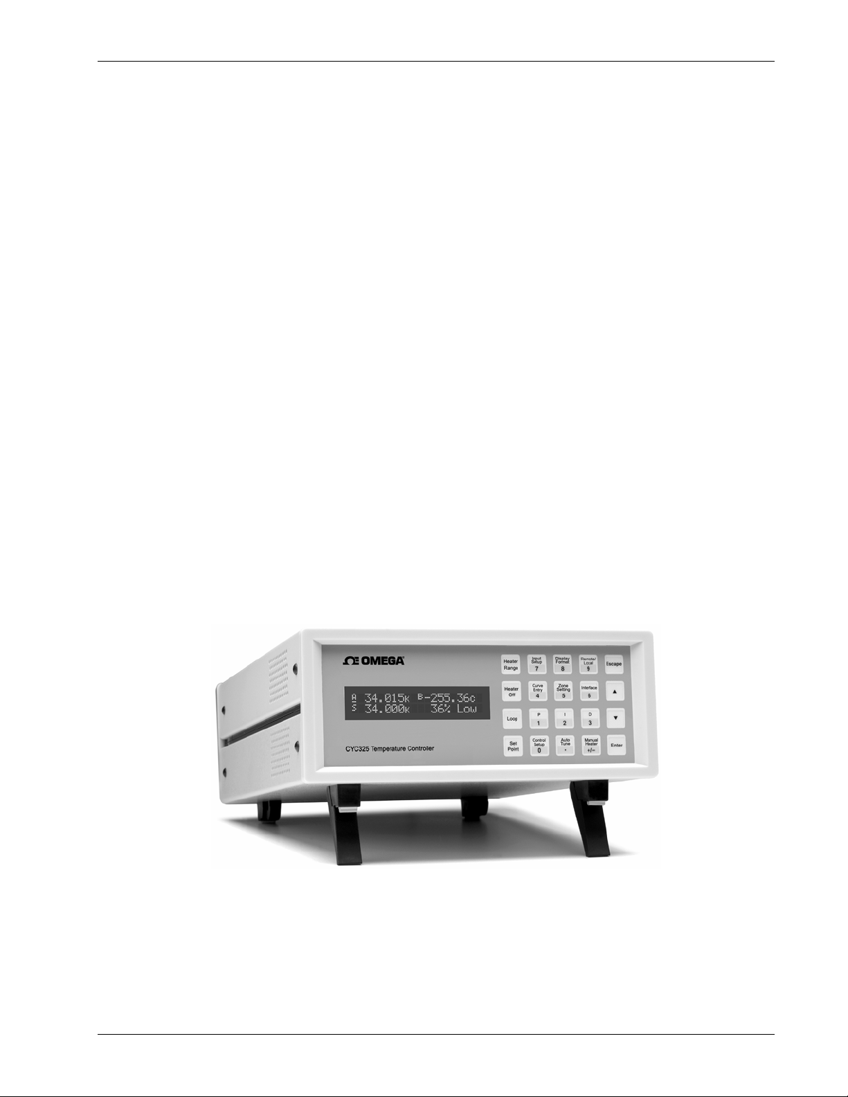
CYC325_Front.bmp
Figure 1-1. Model CYC325 Front View
Introduction 1-1
Page 12
Product Description (Continued)
Omega Model CYC325 Temperature Controller User’s Manual
Temperature Control
The Model CYC325 temperature controller offers two independent proportional-integral-derivative (PID) control loops.
A PID algorithm calculates control output based on temperature setpoint and feedback from the control sensor.
Wide tuning parameters accommodate most cryogenic cooling systems and many small high-temperature ovens.
A high-resolution digital-to-analog converter generates a smooth control output. The user can set the PID values
or the AutoTuning feature of the Model CYC325 can automate the tuning process.
Control loop 1 heater output for the Model CYC325 is a well-regulated variable DC current source. The output can
provide up to 25 W of continuous power to a 50 Ω or 25 Ω heater load, and includes a lower range for systems with less
cooling power. Control loop 2 heater output is a single-range, variable DC voltage source. The output can source up to
0.2 A, providing 2 W of heater power at the 50 Ω setting or 1 W at the 25 Ω setting. When not being used for
temperature control, the loop 2 heater output can be used as a manually controlled voltage source. The output voltage can
vary from 0 to 10 V on the 50 Ω setting, or 0 to 5 V on the 25 Ω setting. Both heater outputs are referenced to chassis
ground. The setpoint ramp feature allows smooth continuous setpoint changes and can also make the approach to
setpoint more predictable. The zone feature can automatically change control parameter values for operation over a large
temperature range. Ten different temperature zones can be loaded into the instrument, which will select the next
appropriate value on setpoint change.
Interface
The Model CYC325 includes both parallel (IEEE-488) and serial (RS-232C) computer interfaces. In addition to data
gathering, nearly every function of the instrument can be controlled via computer interface. Sensor curves can also be
entered and manipulated through either interface using the curve handler software program.
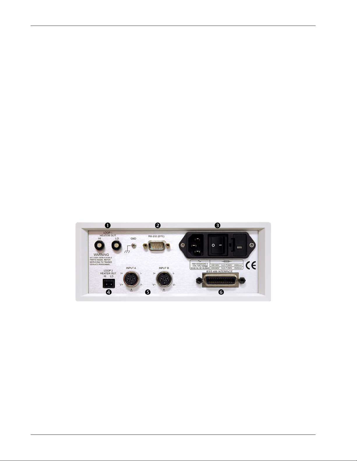
n Loop 1 heater output
o Serial (RS-232C) I/O (DTE)
p Line input assembly
q Loop 2 heater output
r Sensor input connectors
s IEEE-488 interface
Figure 1-2. Model CYC325 Rear Panel Connections
1-2 Introduction
Page 13
Omega Model CYC325 Temperature Controller User’s Manual
Configurable Display
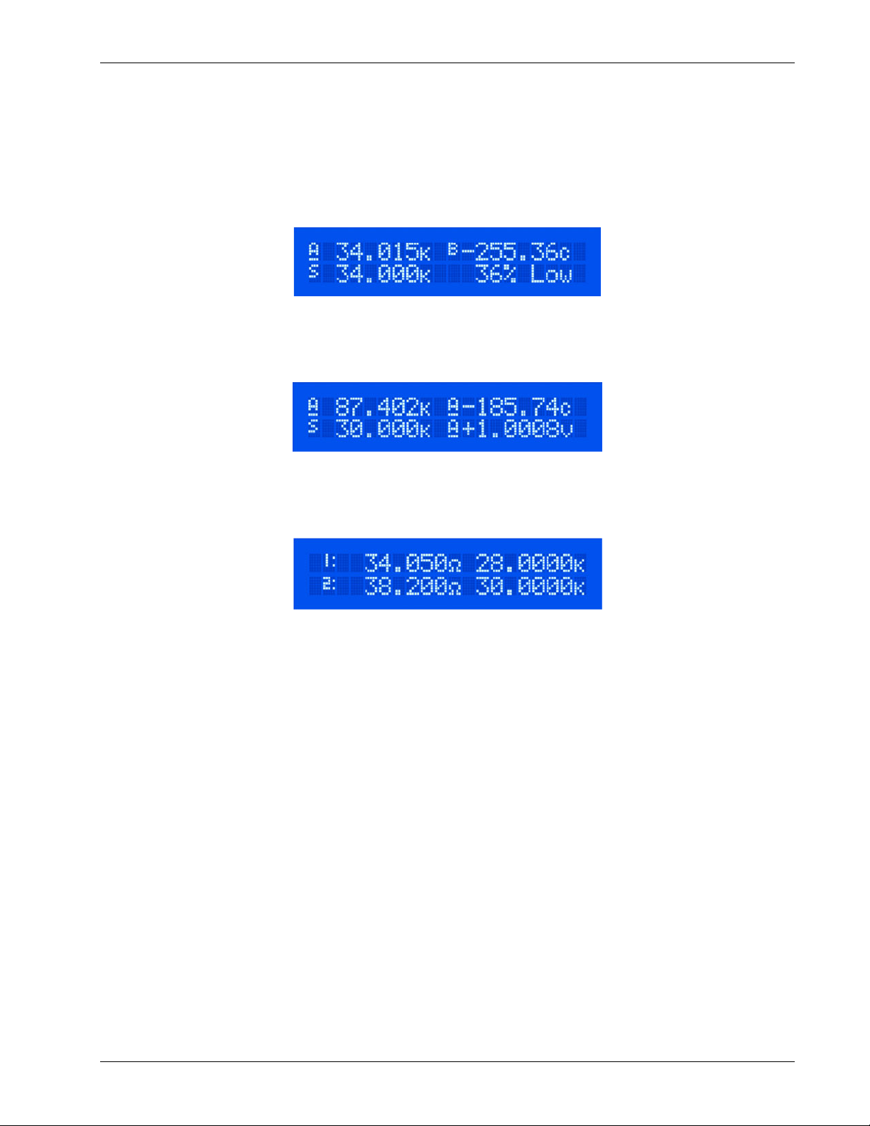
The Model CYC325 offers a bright, easy to read LCD display that simultaneously displays up to four readings. Display
data includes input and source annunciators for each reading. All four display locations can be configured by the user.
Data from either input can be assigned to any of the four locations, and the user’s choice of temperature or sensor units
can be displayed. Heater range and control output as current or power can be continuously displayed for immediate
feedback on control operation. The channel A or B indicator is underlined to indicate which channel is being controlled
by the displayed control loop.
Normal (Default) Display Configuration
The display provides four reading locations. Readings from each input and the control setpoint can be expressed in any
combination of temperature or sensor units, with heater output expressed as a percent of full scale current or power.
Flexible Configuration
Reading locations can be configured by the user to meet application needs. The character preceding the reading indicates
input A or B or setpoint S. The character following the reading indicates measurement units.
Curve Entry
The Model CYC325 display offers the flexibility to support curve, SoftCal™, and zone entry. Curve entry may be
performed accurately and to full resolution via the display and keypad as well as computer interface.
Introduction 1-3
Page 14

Omega Model CYC325 Temperature Controller User’s Manual
1.1 SENSOR SELECTION
Table 1-1. Sensor Temperature Range
Diodes
Positive Temperature
Coefficient (PTC) RTDs
Negative Temperature
Coefficient (NTC) RTDs 1
Silicon Diode CY670-SD 1.4 K to 500 K
Silicon Diode CY670E-BR 30 K to 500 K
Silicon Diode DT-414 1.4 K to 375 K
Silicon Diode DT-421 1.4 K to 325 K
Silicon Diode CY7-SD 1.4 K to 500 K
Silicon Diode CY7-SD7 10 K to 500 K
GaAlAs Diode TG-120-P 1.4 K to 325 K
GaAlAs Diode TG-120-PL 1.4 K to 325 K
GaAlAs Diode TG-120-SD 1.4 K to 500 K
100 Ω Platinum
100 Ω Platinum
Rhodium-Iron RF-800-4 1.4 K to 500 K
Rhodium-Iron RF-100T/U 1.4 K to 325 K
Cernox™ CX-1010 2 K to 325 K 4
Cernox CX-1030-HT 3.5 K to 420 K
Cernox CX-1050-HT 4 K to 420 K
Cernox CX-1070-HT 15 K to 420 K 2
Cernox CX-1080-HT 50 K to 420 K 2
Germanium GR-200A/B-1000 2.2 K to 100 K 3 Not Recommended
Germanium GR-200A/B-1500 2.6 K to 100 K 3 Not Recommended
Model Useful Range Magnetic Field Use
T ≥ 60 K & B ≤ 3 T
T ≥ 60 K & B ≤ 3 T
T ≥ 60 K & B ≤ 3 T
T ≥ 60 K & B ≤ 3 T
T ≥ 60 K & B ≤ 3 T
T ≥ 60 K & B ≤ 3 T
T > 4.2 K & B ≤ 5 T
T > 4.2 K & B ≤ 5 T
T > 4.2 K & B ≤ 5 T
PT-102/3 14 K to 873 K
PT-111 14 K to 673 K
T > 40 K & B ≤ 2.5 T
T > 40 K & B ≤ 2.5 T
T > 77 K & B ≤ 8 T
T > 77 K & B ≤ 8 T
T > 2 & B ≤ 19 T
2,5
2,5
T > 2 & B ≤ 19 T
T > 2 & B ≤ 19 T
T > 2 & B ≤ 19 T
T > 2 & B ≤ 19 T
Germanium GR-200A/B-2500 3.1 K to 100 K 3 Not Recommended
Carbon-Glass CGR-1-500 4 K to 325 K 4
Carbon-Glass CGR-1-1000 5 K to 325 K 4
Carbon-Glass CGR-1-2000 6 K to 325 K 4
Rox™ RX-102A 1.4 K to 40 K
4
T > 2 K to ≤ 19 T
T > 2 K to ≤ 19 T
T > 2 K to ≤ 19 T
T > 2 K to ≤ 10 T
Type K 9006-006 3.2 K to 1505 K Not Recommended
Thermocouples
Type E 9006-004 3.2 K to 934 K Not Recommended
Chromel-AuFe 0.07% 9006-002 1.2 K to 610 K Not Recommended
1
Single excitation current may limit the low temperature range of NTC resistors.
2
Non-HT version maximum temperature: 325 K.
3
Low temperature limited by input resistance range.
4
Low temperature specified with self-heating error: ≤5 mK.
5
Low temperature specified with self-heating error: ≤12 mK.
Silicon diodes are the best choice for general cryogenic use from 1.4 K to above room temperature. Diodes are
economical to use because they follow a standard curve and are interchangeable in many applications. They are
not suitable for use in ionizing radiation or magnetic fields.
Cernox™ thin-film RTDs offer high sensitivity and low magnetic field-induced errors over the 2 K to 420 K
temperature range. Cernox sensors require calibration.
Platinum RTDs offer high uniform sensitivity from 30 K to over 800 K. With excellent reproducibility, they are
useful as thermometry standards. They follow a standard curve above 70 K and are interchangeable in many
applications.
1-4 Introduction
Page 15
Omega Model CYC325 Temperature Controller User’s Manual
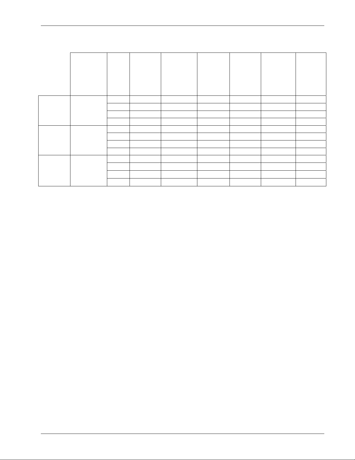
Table 1-2. Typical Sensor Performance
Example Omega
Sensor
Silicon Diode CY670-SD with
1.4H calibration
Temp
Nominal
Resistance/
Voltage
Typical Sensor
Sensitivity
1
Measurement
Resolution:
Temperature
Equivalents
1.4 K 1.644 V -12.49 mV/K 0.8 mK ±13 mK ±25 mK ±1.6 mK
77 K 1.028 V -1.73 mV/K 5.8 mK ±76 mK ±98 mK ±11.6 mK
Electronic
Accuracy:
Temperature
Equivalents
300 K 0.5597 V -2.3 mV/K 4.4 mK ±47 mK ±79 mK ±8.8 mK
500 K 0.0907 V -2.12 mV/K 4.8 mK ±40 mK ±90 mK ±9.6 mK
Silicon Diode CY7-SD-4 with
1.4H calibration
1.4 K 1.6981 V -13.1 mV/K 0.8 mK ±13 mK ±25 mK ±1.6 mK
77 K 1.0203 V -1.92 mV/K 5.2 mK ±69 mK ±91 mK ±10.4 mK
300 K 0.5189 V -2.4 mV/K 4.2 mK ±45 mK ±77 mK ±8.4 mK
475 K 0.0906 V -2.22 mV/K 4.6 mK ±39 mK ±89 mK ±9.2 mK
100 Ω
Platinum
RTD 500 Ω
PT-103 with
1.4J calibration
Full Scale
1
Typical sensor sensitivities were taken from representative calibrations for the sensor listed.
2
Control stability of the electronics only, in an ideal thermal system.
475 K 0.3778 V -3.15 mV/K 6.4 mK ±38 mK ±88 mK ±12.8 mK
30 K
77 K
300 K
3.660 Ω 0.191 Ω/K
20.38 Ω 0.423 Ω/K
110.35 Ω 0.387 Ω/K
10.5 mK ±23 mK ±33 mK ±21 mK
4.8 mK ±15 mK ±27 mK ±9.6 mK
5.2 mK ±39 mK ±62 mK ±10.4 mK
3 Accuracy specification does not include errors from room temperature compensation.
Temperature
Accuracy
including
Electronic
Accuracy,
CalCurve™, and
Calibrated
Sensor
Electronic
Control
2
:
Stability
Temperature
Equivalents
Introduction 1-5
Page 16
Omega Model CYC325 Temperature Controller User’s Manual
1.2 SPECIFICATIONS
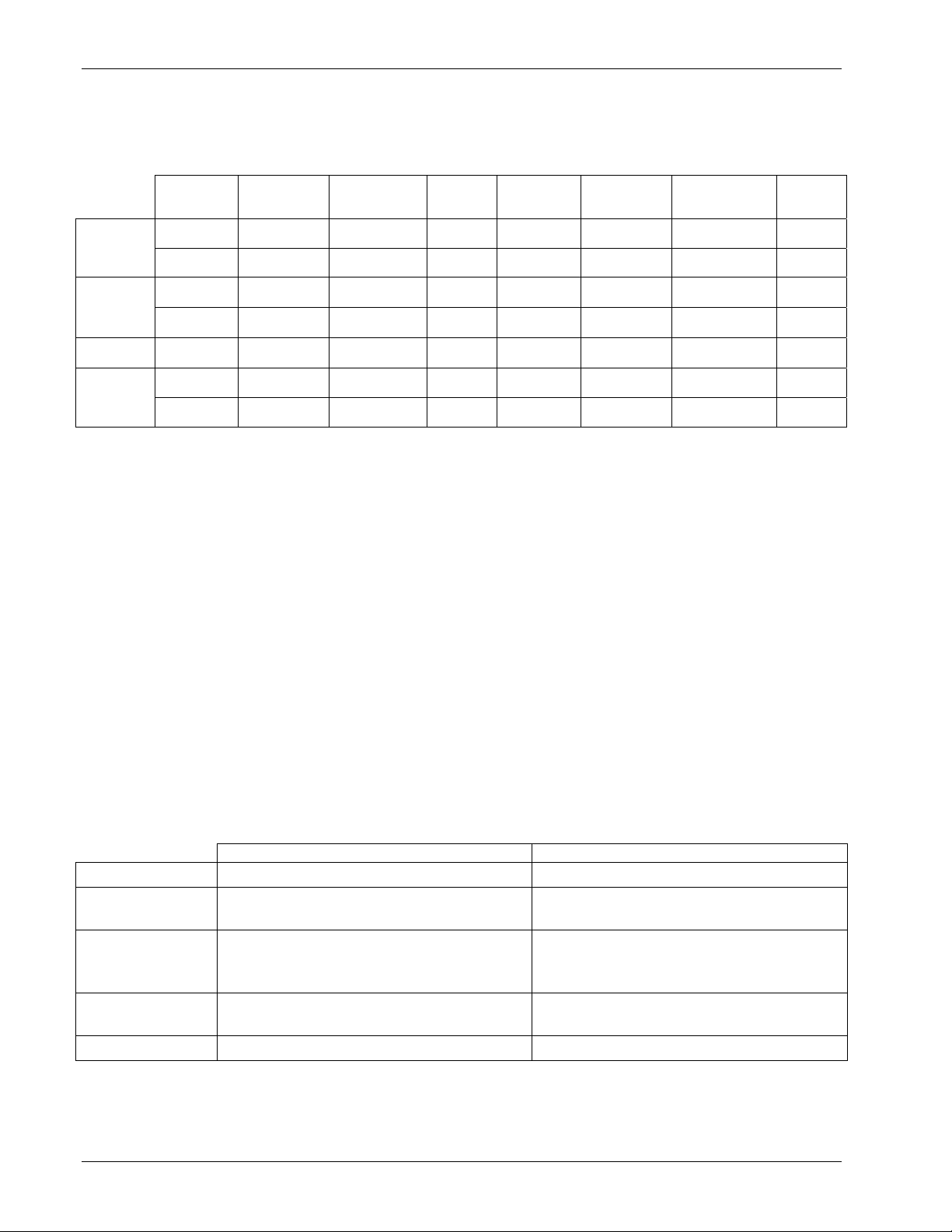
Input Specifications
Diode
PTC RTD
NTC RTD Negative
Thermocouple
1
Control stability of the electronics only, in ideal thermal system
2
Current source error has negligible effect on measurement accuracy
3
Diode input excitation can be set to 1 mA
4
Current source error is removed during calibration
5
Accuracy specification does not include errors from room temperature compensation
Sensor
Temperature
Coefficient
Negative 0 V to 2.5 V 10 µA ±0.05%
Negative 0 V to 7.5 V 10 µA ±0.05%
Positive
Positive
Positive ±25 mV NA 1 µV 0.4 µV
Positive ±50 mV NA 1 µV 20 µV
Input
Range
0 Ω to 500 Ω
0 Ω to 5000 Ω
0 Ω to 7500 Ω
Excitation
Current
1 mA4
4
1 mA
10 µA ±0.05%
Display
Resolution
2,3
100 µV 0.4 µV
2,3
100 µV 10 µV
10 mΩ 2 mΩ
100 mΩ 20 mΩ
100 mΩ 40 mΩ
Measurement
Resolution
Electronic
Accuracy
(at 25 °C)
±80 µV
±0.005% of rdg
±80 µV
±0.01% of rdg
±0.004 Ω
±0.01% of rdg
±0.04 Ω
±0.02% of rdg
±0.1 Ω
±0.04% of rdg
±1 µV
±0.05% of rdg
±1 µV
±0.05% of rdg
Measurement
Temperature
Coefficient
(10 µV +
0.0005% of rdg)/°C
(20 µV +
0.0005% of rdg)/°C
(0.2 mΩ +
0.0005% of rdg)/°C
(0.2 mΩ +
0.0005% of rdg)/°C
(2 mΩ +
0.0005% of rdg)/°C
(0.2 µV +
0.0015% of rdg)/°C
(0.2 µV +
0.0015% of rdg)/°C
Thermometry
Number of inputs 2
Input configuration Each input is factory configured for either diode / RTD or thermocouple
Isolation Sensor inputs optically isolated from other circuits but not each other
A/D resolution 24-bit
Input accuracy Sensor dependent, refer to Input Specifications table
Measurement resolution Sensor dependent, refer to Input Specifications table
Max update rate: 10 rdg/s on each input, (except 5 rdg/s on input A when configured as thermocouple)
User curves Room for 15 200-point CalCurves
SoftCal
™ Improves accuracy of CY7 diodes to ±0.25 K from 30 K to 375 K. Improves accuracy
™ or user curves
of platinum RTDs to ±0.25 K from 70 K to 325 K. Stored as user curves.
Filter Averages 2 to 64 input readings
Sensor Input Configuration
Diode/RTD Thermocouple
Measurement type 4-lead differential 2-lead, room temperature compensated
Excitation
Constant current with current reversal for
RTDs
NA
Diodes: Silicon, GaAlAs RTDs: 100 Ω
Supported sensors
Standard curves
Platinum, 1000 Ω Platinum, Germanium,
Carbon-Glass, Cernox™, and Rox™
CY7, DT-500D. CY670, PT-100, PT-1000,
RX-102A, RX-202A
Most thermocouple types
Type E, Type K, Type T, AuFe 0.07% vs. Cr,
AuFe 0.03% vs Cr
Input connector 6-pin DIN Ceramic isothermal block
Electronic
Control
Stability
±20 µV
±40 µV
±4 mΩ
±40 mΩ
±80 mΩ
±0.8 µV
±0.8 µV
1
1-6 Introduction
Page 17

Omega Model CYC325 Temperature Controller User’s Manual
Specifications (Continued)
Control
Control loops 2
Control type Closed loop digital PID with manual heater output or open loop
Tuning Autotune (one loop at a time), PID, PID zones
Control stability Sensor dependent, refer to Input Specifications table
PID control settings:
Proportional (Gain) 0 to 1000 with 0.1 setting resolution
Integral (Reset) 1 to 1000 (1000/s) with 0.1 setting resolution
Derivative (Rate) 1 to 200% with 1% resolution
Manual output 0 to 100% with 0.01% setting resolution
Zone control 10 temperature zones with P, I, D, manual heater out, and heater range
Setpoint ramping 0.1 K/min to 100 K/min
Loop 1 Heater Output
Type Variable DC current source
D/A resolution 16-bit
25
Ω
Setting 50 Ω Setting
Max power 25 W 25 W
Max current 1 A 0.71 A
Voltage compliance (min) 25 V 35.4 V
Heater load range
Heater load for max power
20 Ω to 25 Ω 40 Ω to 50 Ω
25
Ω 50 Ω
Ranges 2 (2.5 W/25 W)
Heater noise (<1 kHz) 1 µA + 0.01% of output
Grounding Output referenced to chassis ground
Heater connector Dual banana
Safety limits Curve temperature, power up heater off, short circuit protection
Loop 2 Heater Output
Type Variable DC voltage source
D/A resolution 16-bit
25
Ω
Setting 50 Ω Setting
Max power 1 W 2 W
Max voltage 5 V 10 V
Current compliance (min) 0.2 A 0.2 A
Heater load range
Heater load for max power
≥ 25 Ω ≥ 50 Ω
25 Ω 50 Ω
Ranges 1
Heater noise (<1 kHz) 50 µV + 0.01% of output
Grounding Output referenced to chassis ground
Heater connector Detachable terminal block
Safety limits Curve temperature, power up heater off, short circuit protection
Front Panel
Display 2-line × 20-character liquid crystal display with 5.5 mm high characters
Number of reading displays 1 to 4
Display units K, °C, V, mV, Ω
Reading source Temperature, sensor units
Display update rate 2 rdg/s
Temperature display resolution 0.001° from 0° to 99.999°, 0.01° from 100° to 999.99°, 0.1° above 1000°
Sensor units display resolution Sensor dependent, to 5 digits
Other displays Setpoint, heater range and heater output (user selected)
Setpoint setting resolution Same as display resolution (actual resolution is sensor dependent)
Heater output display Numeric display in percent of full scale for power or current
Heater output resolution 1%
Display annunciators Control Input, Remote, Autotune
Keypad 20-key membrane, numeric and specific functions
Front panel features Front panel curve entry, keypad lock-out
Introduction 1-7
Page 18

Omega Model CYC325 Temperature Controller User’s Manual
Specifications (Continued)
Interface
IEEE-488.2 interface:
Features SH1, AH1, T5, L4, SR1, RL1, PP0, DC1, DT0, C0, E1
Reading rate To 10 rdg/s on each input
Serial interface
Electrical format RS-232C
Baud rates 9600, 19200, 38400, 57600
Connector 9-pin D-style, DTE configuration
Reading rate To 10 rdg/s on each input
General
Ambient temperature 15 °C to 35 °C at rated accuracy. 5 °C to 40 °C at reduced accuracy
Power requirement 100, 120, 220, 240 VAC, +6% –10%, 50 or 60 Hz, 85 VA
Size 216 mm W × 89 mm H × 368 mm D (8.5 in × 3.5 in × 14.5 in), half rack
Weight 4.0 kg (8.8 lb)
Approval CE mark (contact Omega for availability)
Ordering Information
Standard Temperature Controllers, all features included:
Part Number Description (Input configuration cannot be changed in the field)
CYC325 Two diode / RTD inputs
CYC325-T1 One diode / RTD, one thermocouple input
CYC325-T2 Two thermocouple inputs
Refer to Chapter 7 of this manual for a complete description of Model CYC325 options and accessories.
Specifications subject to change without notice.
1.3 SAFETY SUMMARY
Observe these general safety precautions during all phases of instrument operation, service, and repair. Failure to comply
with these precautions or with specific warnings elsewhere in this manual violates safety standards of design,
manufacture, and intended instrument use. Omega, Inc. assumes no liability for Customer failure to comply with these
requirements.
The Model CYC325 protects the operator and surrounding area from electric shock or burn, mechanical hazards,
excessive temperature, and spread of fire from the instrument. Environmental conditions outside of the conditions below
may pose a hazard to the operator and surrounding area.
• Indoor use.
• Altitude to 2000 m.
• Temperature for safe operation: 5 °C to 40 °C.
• Maximum relative humidity: 80% for temperature up to 31 °C decreasing linearly to 50% at 40 °C.
• Power supply voltage fluctuations not to exceed ±10% of the nominal voltage.
• Overvoltage category II.
• Pollution degree 2.
1-8 Introduction
Page 19
Safety Summary (Continued)
Omega Model CYC325 Temperature Controller User’s Manual
Ground the Instrument
To minimize shock hazard, the instrument is equipped with a three-conductor AC power cable. Plug the power cable
into an approved three-contact electrical outlet or use a three-contact adapter with the grounding wire (green) firmly
connected to an electrical ground (safety ground) at the power outlet. The power jack and mating plug of the power
cable meet Underwriters Laboratories (UL) and International Electrotechnical Commission (IEC) safety standards.
Ventilation
The instrument has ventilation holes in its side covers. Do not block these holes when the instrument is operating.
Do Not Operate in an Explosive Atmosphere
Do not operate the instrument in the presence of flammable gases or fumes. Operation of any electrical instrument in
such an environment constitutes a definite safety hazard.
Keep Away from Live Circuits
Operating personnel must not remove instrument covers. Refer component replacement and internal adjustments to
qualified maintenance personnel. Do not replace components with power cable connected. To avoid injuries, always
disconnect power and discharge circuits before touching them.
Do Not Substitute Parts or Modify Instrument
Do not install substitute parts or perform any unauthorized modification to the instrument. Return the instrument to an
authorized Omega, Inc. representative for service and repair to ensure that safety features are maintained.
Cleaning
Do not submerge instrument. Clean only with a damp cloth and mild detergent. Exterior only.
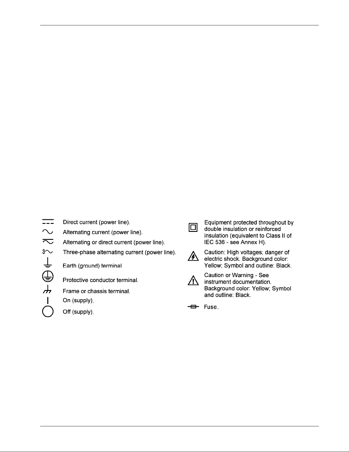
1.4 SAFETY SYMBOLS
Introduction 1-9
Page 20

Omega Model CYC325 Temperature Controller User’s Manual
This Page Intentionally Left Blank
1-10 Introduction
Page 21

Omega Model CYC325 Temperature Controller User’s Manual
CHAPTER 2
COOLING SYSTEM DESIGN
2.0 GENERAL
Selecting the proper cryostat or cooling source is probably the most important decision in designing a temperature
control system. The cooling source defines minimum temperature, cool-down time, and cooling power. (Information on
choosing a cooling source is beyond the scope of this manual.) This chapter provides information on how to get the best
temperature measurement and control from cooling sources with proper setup including sensor and heater installation.
2.1 TEMPERATURE SENSOR SELECTION
This section attempts to answer some of the basic questions concerning temperature sensor selection. Additional useful
information on temperature sensor selection is available in the Omega Temperature Handbook.
2.1.1 Temperature Range
Several important sensor parameters must be considered when choosing a sensor. The first is temperature range. The
experimental temperature range must be known when choosing a sensor. Some sensors can be damaged by temperatures
that are either too high or too low. Manufacturer recommendations should always be followed.
Sensor sensitivity is also dependent on temperature and can limit the useful range of a sensor. It is important not to
specify a range larger than necessary. If an experiment is being done at liquid helium temperature, a very high sensitivity
is needed for good measurement resolution at that temperature. That same resolution may not be required to monitor
warm up to room temperature. Two different sensors may be required to tightly cover the range from helium to room
temperature, but lowering the resolution requirement on warm up may allow a less expensive, one sensor solution.
Another thing to consider when choosing a temperature sensor is that instruments like the Model CYC325 are not able to
read some sensors over their entire temperature range. The Model CYC325 is limited to above 1 kelvin (K) in its
standard configuration.
2.1.2 Sensor Sensitivity
Temperature sensor sensitivity is a measure of how much a sensor signal changes when the temperature changes. It is an
important sensor characteristic because so many measurement parameters are related to it. Resolution, accuracy, noise
floor, and even control stability depend on sensitivity. Many sensors have different sensitivities at different temperatures.
For example, a platinum sensor has good sensitivity at higher temperatures but has limited use below 30 K because its
sensitivity drops sharply. It is difficult to determine if a sensor has adequate sensitivity over the experimental
temperature range. This manual has specifications (Section 1.2) that include sensor sensitivity translated into temperature
resolution and accuracy at different points. This is typical sensor response and can be used as a guide when choosing a
sensor to be used with the Model CYC325.
2.1.3 Environmental Conditions
The experimental environment is also important when choosing a sensor. Environmental factors such as high vacuum,
magnetic field, corrosive chemicals, or even radiation can limit the use of some types of sensors.
Experiments done in magnetic fields are becoming very common. Field dependence of temperature sensors is an
important selection criteria for sensors used in these experiments. This manual briefly qualifies the field dependence of
most common sensors in the specifications (Section 1.2).
Cooling System Design 2-1
Page 22

Omega Model CYC325 Temperature Controller User’s Manual
2.1.4 Measurement Accuracy
Temperature measurements have several sources of error that reduce accuracy. Be sure to account for errors induced by
both the sensor and the instrumentation when computing accuracy. The instrument has measurement error in reading the
sensor signal and error in calculating a temperature using a temperature response curve. Error results from the sensor
being compared to a calibration standard and the temperature response of a sensor will shift with time and with repeated
thermal cycling (from very cold temperatures to room temperature). Instrument and sensor makers specify these errors
but there are things a user can do to maintain good accuracy. For example, choose a sensor that has good sensitivity in
the most critical temperature range, as sensitivity can minimize the effect of most error sources. Install the sensor
properly following guidelines in Section 2.3. Have the sensor and instrument periodically recalibrated, or in some other
way null the time dependent errors. Use a sensor calibration that is appropriate for the accuracy requirement.
2.1.5 Sensor Package
Many types of sensors can be purchased in different packages. Some types of sensors can even be purchased as bare
chips without any package. A sensor package generally determines its size, thermal and electrical contact to the outside,
and sometimes limits temperature range. When different packages are available for a sensor, the user should consider the
mounting surface for the sensor and how leads will be heat sinked when choosing.
2.2 CALIBRATED SENSORS
There can sometimes be confusion in the difficult task of choosing the right sensor, getting it calibrated, translating the
calibration data into a temperature response curve that the Model CYC325 can understand, then getting the curve loaded
into the instrument. Omega provides a variety of calibration and curve loading services to fit different accuracy
requirements and budgets.
2.2.1 Traditional Calibration
Calibration is done by comparing a sensor with an unknown temperature response to an accepted standard. Omega
temperature standards are traceable to the U.S. National Institute of Standards and Testing (NIST) or the National
Physical Laboratory in Great Britain. Calibrated sensors are more expensive than uncalibrated sensors of the same type
because of the labor and capitol equipment used in the process.
This type of calibration provides the most accurate temperature sensors available from Omega. Errors from sensor
calibration are almost always smaller than the error contributed by the Model CYC325.
Calibrated sensors include the measured test data printed and plotted, the coefficients of a Chebychev polynomial that
has been fitted to the data, and two tables of data points to be used as interpolation tables. Both interpolation tables are
optimized to allow accurate temperature conversion. The smaller table, called a breakpoint interpolation table, is sized to
fit into instruments like the Model CYC325 where it is called a temperature response curve. Getting a curve into a Model
CYC325 may require a CalCurve described below or hand entering through the instrument front panel.
It is important to look at instrument specifications before ordering calibrated sensors. A calibrated sensor is required
when a sensor does not follow a standard curve if the user wishes to display in temperature. Otherwise the Model
CYC325 will operate in sensor units like ohms or volts. The Model CYC325 may not work over the full temperature
range of some sensors. The standard inputs in are limited to operation above 1 K even with sensors that can be calibrated
to 50 mK.
2.2.2 SoftCal™
SoftCal is a good solution for applications that do not require the accuracy of a traditional calibration. The SoftCal
algorithm uses the well-behaved nature of sensors that follow a standard curve to improve the accuracy of individual
sensors. A few known temperature points are required to perform SoftCal.
A CalCurve may be required to get the breakpoint table into a Model CYC325 where it is called a temperature response
curve. Refer to Section 2.2.4.
The Model CYC325 can also perform a SoftCal calibration. The user must provide one, two, or three known temperature
reference points. The range and accuracy of the calibration is based on these points. Refer to Section 5.3.
2-2 Cooling System Design
Page 23
Omega Model CYC325 Temperature Controller User’s Manual
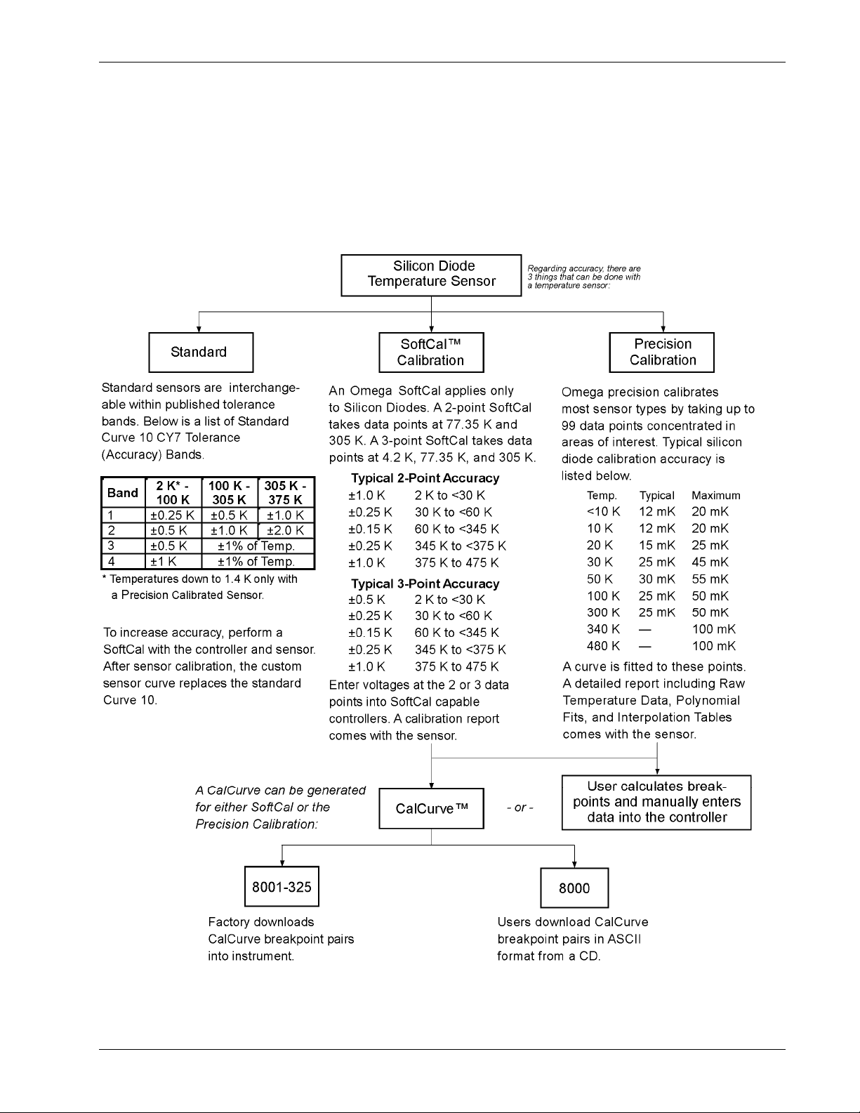
2.2.3 Standard Curves
Some types of sensors behave in a very predictable manner and a standard temperature response curve can be created for
them. Standard curves are a convenient and inexpensive way to get reasonable temperature accuracy. Sensors that have a
standard curve are often used when interchangeability is important. Some individual sensors are selected for their ability
to match a published standard curve and sold at a premium, but in general these sensors do not provide the accuracy of a
calibrated sensor. For convenience, the Model CYC325 has several standard curves included in firmware.
C-CYC325-2-1.bmp
Figure 2-1. Silicon Diode Sensor Calibrations and CalCurve
Cooling System Design 2-3
Page 24

Omega Model CYC325 Temperature Controller User’s Manual
2.3 SENSOR INSTALLATION
This section highlights some of the important elements of proper sensor installation. For more detailed information,
Omega sensors are shipped with installation instructions that cover that specific sensor type and package. The Omega
Temperature Catalog includes an installation section as well. To further help users properly install sensors, Omega offers
a line of cryogenic accessories. Many of the materials discussed are available through Omega and can be ordered with
sensors or instruments.
2.3.1 Mounting Materials
Choosing appropriate mounting materials is very important in a cryogenic environment. The high vacuum used to
insulate cryostats is one source of problems. Materials used in these applications should have a low vapor pressure so
they do not evaporate or out-gas and spoil the vacuum insulation. Metals and ceramics do not have this problem but
greases and varnishes must be checked. Another source of problems is the wide extremes in temperature most sensors
are exposed to. The linear expansion coefficient of materials becomes important when temperature changes are so large.
Never try to permanently bond materials with linear expansion coefficients that differ by more than three. A flexible
mounting scheme should be used or the parts will break apart, potentially damaging them. The thermal expansion or
contraction of rigid clamps or holders could crush fragile samples or sensors that do not have the same coefficient.
Thermal conductivity is a property of materials that can change with temperature. Do not assume that a heat sink grease
that works well at room temperature and above will do the same job at low temperatures.
2.3.2 Sensor Location
Finding a good place to mount a sensor in an already crowded cryostat is never easy. There are fewer problems if the
entire load and sample holder are at the same temperature. Unfortunately, this not the case in many systems.
Temperature gradients (differences in temperature) exist because there is seldom perfect balance between the cooling
source and heat sources. Even in a well-controlled system, unwanted heat sources like thermal radiation and heat
conducting through mounting structures can cause gradients. For best accuracy, sensors should be positioned near the
sample, so that little or no heat flows between the sample and sensor. This may not, however, be the best location for
temperature control as discussed below.
2.3.3 Thermal Conductivity
The ability of heat to flow through a material is called thermal conductivity. Good thermal conductivity is important in
any part of a cryogenic system that is intended to be the same temperature. Copper and aluminum are examples of metals
that have good thermal conductivity, while stainless steel does not. Non-metallic, electrically-insulating materials like
alumina oxide and similar ceramics have good thermal conductivity, while G-10 epoxy-impregnated fiberglass does not.
Sensor packages, cooling loads, and sample holders should have good thermal conductivity to reduce temperature
gradients. Surprisingly, the connections between thermally conductive mounting surfaces often have very poor thermal
conductivity.
2.3.4 Contact Area
Thermal contact area greatly affects thermal conduction because a larger area has more opportunity to transfer heat. Even
when the size of a sensor package is fixed, thermal contact area can be improved with the use of a gasket material. A soft
gasket material forms into the rough mating surface to increase the area of the two surfaces that are in contact. Good
gasket materials are soft, thin, and have good thermal conductivity. They must also withstand the environmental
extremes. Indium foil and cryogenic grease are good examples.
2-4 Cooling System Design
Page 25
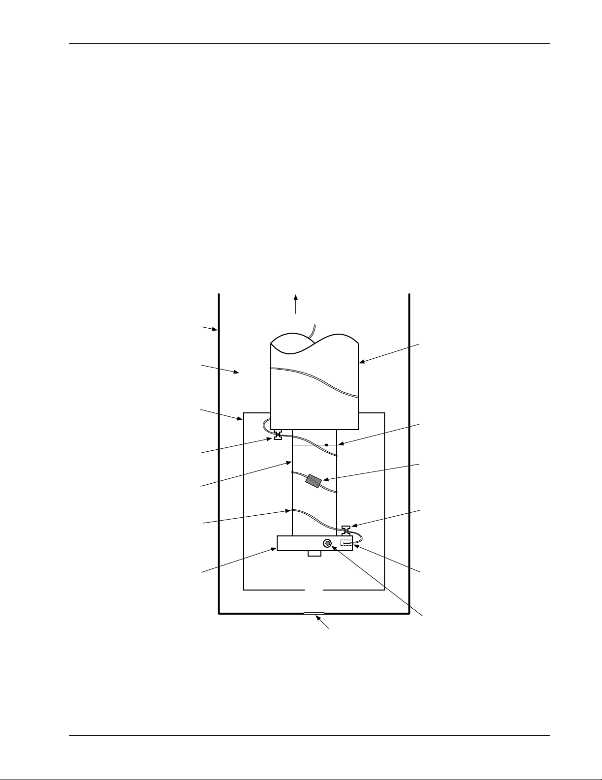
Omega Model CYC325 Temperature Controller User’s Manual
2.3.5 Contact Pressure
When sensors are permanently mounted, the solder or epoxy used to hold the sensor act as both gasket and adhesive.
Permanent mounting is not a good solution for everyone because it limits flexibility and can potentially damage sensors.
Much care should be taken not to over heat or mechanically stress sensor packages. Less permanent mountings require
some pressure to hold the sensor to its mounting surface. Pressure greatly improves the action of gasket material to
increase thermal conductivity and reduce thermal gradients. A spring clamp is recommended so that different rates of
thermal expansion do not increase or decrease pressure with temperature change.
2.3.6 Lead Wire
Different types of sensors come with different types and lengths of electrical leads. In general a significant length of lead
wire must be added to the sensor for proper heat sinking and connecting to a bulkhead connector at the vacuum
boundary. The lead wire must be a good electrical conductor, but should not be a good thermal conductor, or heat will
transfer down the leads and change the temperature reading of the sensor. Small 30 to 40 AWG wire made of an alloy
like phosphor bronze is much better than copper wire. Thin wire insulation is preferred and twisted wire should be used
to reduce the effect of RF noise if it is present. The wire used on the room temperature side of the vacuum boundary is
not critical so copper cable is normally used.
To Room
Temperature
Vacuum Shroud
Refrigerator
Expander
Vacuum Space
Radiation Shield
Dental Floss
Tie-Down
Thermal Anchor
(Bobbin)
-or-
Cryogenic Tape
Refrigerator
Second
Stage
Thermal Anchor
Cryogenic Wire
diameter,
(small
(Bobbin)
large AWG )
Cold Stage and
Sensor
Sample Holder
Drawin g
Not To Scale
Optical Window
Heater
(wiring not shown
for clarity)
(If Required)
P-CYC325-2-2.bmp
Figure 2-2. Typical Sensor Installation In A Mechanical Refrigerator
Cooling System Design 2-5
Page 26

Omega Model CYC325 Temperature Controller User’s Manual
2.3.7 Lead Soldering
When additional wire is soldered to short sensor leads, care must be taken not to overheat the sensor. A heat sink such as
a metal wire clamp or alligator clip will heat sink the leads and protect the sensor. Leads should be tinned before bonding
to reduce the time that heat is applied to the sensor lead. Solder flux should be cleaned after soldering to prevent
corrosion.
2.3.8 Heat Sinking Leads
Sensor leads can be a significant source of error if they are not properly heat sinked. Heat will transfer down even small
leads and alter the sensor reading. The goal of heat sinking is to cool the leads to a temperature as close to the sensor as
possible. This can be accomplished by putting a significant length of lead wire in thermal contact with every cooled
surface between room temperature and the sensor. Lead wires can be adhered to cold surfaces with varnish over a thin
electrical insulator like cigarette paper. They can also be wound onto a bobbin that is firmly attached to the cold surface.
Some sensor packages include a heat sink bobbin and wrapped lead wires to simplify heat sinking.
2.3.9 Thermal Radiation
Thermal (black body) radiation is one of the ways heat is transferred. Warm surfaces radiate heat to cold surfaces even
through a vacuum. The difference in temperature between the surfaces is one thing that determines how much heat is
transferred. Thermal radiation causes thermal gradients and reduces measurement accuracy. Many cooling systems
include a radiation shield. The purpose of the shield is to surround the load, sample, and sensor with a surface that is at or
near their temperature to minimize radiation. The shield is exposed to the room temperature surface of the vacuum
shroud on its outer surface, so some cooling power must be directed to the shield to keep it near the load temperature.
If the cooling system does not include an integrated radiation shield (or one cannot be easily made), one alternative is to
wrap several layers of super-insulation (aluminized mylar) loosely between the vacuum shroud and load. This reduces
radiation transfer to the sample space.
2.4 HEATER SELECTION AND INSTALLATION
There is a variety of resistive heaters that can be used as the controlled heating source for temperature control. The
mostly metal alloys like nichrome are usually wire or foil. Shapes and sizes vary to permit installation into different
systems.
2.4.1 Heater Resistance and Power
Cryogenic cooling systems have a wide range of cooling power. The resistive heater must be able to provide sufficient
heating power to warm the system. The Model CYC325 can supply up to 25 W of power to a heater (if the heater
resistance is appropriate). The Model CYC325 heater output current source has a maximum output of 1 A at the 25 Ω
setting, or 0.71 A at the 50 Ω setting. Even though the Model CYC325 main heater output is a current source, it has a
voltage limit (called the compliance voltage) that is set to either 25 V or 35.4 V when the heater resistance is set to 25 Ω
or 50 Ω, respectively. This compliance voltage also limits maximum power.
Voltage Limit:
Current Limit:
Max Power (W) at 25 Ω Setting Max Power (W) at 50 Ω Setting
(25 V)
Resistance (Ω)
2
(1 A)
× Resistance (Ω) (0.71 A)2 × Resistance (Ω)
2
(35.4 V)2
Resistance (Ω)
Both limits are in place at the same time, so the smaller of the two computations gives the maximum power available to
the heater. A heater of 50 Ω at the 50 Ω setting allows the instrument to provide its maximum power of 25 W. A smaller
resistance of 40 Ω at the 50 Ω setting allows about 20 W of power, while a larger resistance of 60 Ω is limited by
compliance voltage to about 21 W. The Model CYC325 is designed to limit the internal power dissipation as a measure
of self-protection. This internal power limit will not allow the output current to rise once the power limit is reached.
The resistor chosen as a heater must be able to withstand the power being dissipated in it. Pre-packaged resistors have a
power specification that is usually given for the resistor in free air. This power may need to be derated if used in a
vacuum where convection cooling cannot take place and it is not adequately heat sinked to a cooled surface.
2-6 Cooling System Design
Page 27

Omega Model CYC325 Temperature Controller User’s Manual
2.4.2 Heater Location
For best temperature measurement accuracy the heater should be located so that heat flow between the cooling power
and heater is minimized. For best control the heater should be in close thermal contact with the cooling power. Geometry
of the load can make one or both of these difficult to achieve. That is why there are several heater shapes and sizes.
2.4.3 Heater Types
Resistive wire like nichrome is the most flexible type of heater available. The wire can be purchased with electrical
insulation and has a predictable resistance per given length. This type of heater wire can be wrapped around a cooling
load to give balanced, even heating of the area. Similar to sensor lead wire, the entire length of the heater wire should be
in good thermal contact with the load to allow for thermal transfer. Heat sinking also protects the wire from over heating
and burning out.
Resistive heater wire is also wound into cartridge heaters. Cartridge heaters are more convenient but are bulky and more
difficult to place on small loads. A typical cartridge is 0.25 inch in diameter and 1 inch long. The cartridge should be
snugly held in a hole in the load or clamped to a flat surface. Heat sinking for good thermal contact is again important.
Foil heaters are thin layers of resistive material adhered to, or screened on to, electrically insulating sheets. There are a
variety of shapes and sizes. The proper size heater can evenly heat a flat surface or around a round load. The entire active
area should be in good thermal contact with the load, not only for maximum heating effect, but to keep spots in the
heater from over heating and burning out.
2.4.4 Heater Wiring
When wiring inside a vacuum shroud, we recommend using 30 AWG copper wire for heater leads. Too much heat can
leak in when larger wire is used. Heat sinking, similar to that used for the sensor leads, should be included so that any
heat leaking in does not warm the load when the heater is not running. The lead wires should be twisted to minimize
noise coupling between the heater and other leads in the system. When wiring outside the vacuum shroud, larger gauge
copper cable can be used, and twisting is still recommended.
2.5 CONSIDERATION FOR GOOD CONTROL
Most of the techniques discussed above to improve cryogenic temperature accuracy apply to control as well. There is an
obvious exception in sensor location. A compromise is suggested below in Section 2.5.3 – Two Sensor Approach.
2.5.1 Thermal Conductivity
Good thermal conductivity is important in any part of a cryogenic system that is intended to be at the same temperature.
Most systems begin with materials that have good conductivity themselves, but as sensors, heaters, sample holders, etc.,
are added to an ever more crowded space, the junctions between parts are often overlooked. In order for control to work
well, junctions between the elements of the control loop must be in close thermal contact and have good thermal
conductivity. Gasket materials should always be used along with reasonable pressure.
2.5.2 Thermal Lag
Poor thermal conductivity causes thermal gradients that reduce accuracy and also cause thermal lag that make it difficult
for controllers to do their job. Thermal lag is the time it takes for a change in heating or cooling power to propagate
through the load and get to the feedback sensor. Because the feedback sensor is the only thing that lets the controller
know what is happening in the system, slow information to the sensor slows the response time. For example, if the
temperature at the load drops slightly below the setpoint, the controller gradually increases heating power. If the
feedback information is slow, the controller puts too much heat into the system before it is told to reduce heat. The
excess heat causes a temperature overshoot, which degrades control stability. The best way to improve thermal lag is to
pay close attention to thermal conductivity both in the parts used and their junctions.
2.5.3 Two-Sensor Approach
There is a conflict between the best sensor location for measurement accuracy and the best sensor location for control.
For measurement accuracy, the sensor should be very near the sample being measured, which is away from the heating
and cooling sources to reduce heat flow across the sample and thermal gradients. The best control stability is achieved
when the feedback sensor is near both the heater and cooling source to reduce thermal lag. If both control stability and
measurement accuracy are critical, it may be necessary to use two sensors, one for each function. Many temperature
controllers including the Model CYC325 have two sensor inputs for this reason.
Cooling System Design 2-7
Page 28

2.5.4 Thermal Mass
Cryogenic designers understandably want to keep the thermal mass of the load as small as possible so the system can
cool quickly and improve cycle time. Small mass can also have the advantage of reduced thermal gradients. Controlling
a very small mass is difficult because there is no buffer to adsorb small changes in the system. Without buffering, small
disturbances can very quickly create large temperature changes. In some systems it is necessary to add a small amount of
thermal mass such as a copper block in order to improve control stability.
2.5.5 System Nonlinearity
Because of nonlinearities in the control system, a system controlling well at one temperature may not control well at
another temperature. While nonlinearities exist in all temperature control systems, they are most evident at cryogenic
temperatures. When the operating temperature changes the behavior of the control loop, the controller must be retuned.
As an example, a thermal mass acts differently at different temperatures. The specific heat of the load material is a major
factor in thermal mass and the specific heat of materials like copper change as much as three orders of magnitude when
cooled from 100 K to 10 K. Changes in cooling power and sensor sensitivity are also sources of nonlinearity.
The cooling power of most cooling sources also changes with load temperature. This is very important when operating at
temperatures near the highest or lowest temperature that a system can reach. Nonlinearities within a few degrees of these
high and low temperatures make it very difficult to configure them for stable control. If difficulty is encountered, it is
recommended to gain experience with the system at temperatures several degrees away from the limit and gradually
approach it in small steps.
Keep an eye on temperature sensitivity. Sensitivity not only affects control stability but it also contributes to the overall
control system gain. The large changes in sensitivity that make some sensors so useful may make it necessary to retune
the control loop more often.
Omega Model CYC325 Temperature Controller User’s Manual
2.6 PID CONTROL
For closed-loop operation, the Model CYC325 temperature controller uses a algorithm called PID control. The control
equation for the PID algorithm has three variable terms: proportional (P), integral (I), and derivative (D). See Figure 2-3.
Changing these variables for best control of a system is called tuning. The PID equation in the Model CYC325 is:
Heater Output P e I e dt D
where the error (e) is defined as: e = Setpoint – Feedback Reading.
Proportional is discussed in Section 2.6.1. Integral is discussed in Section 2.6.2. Derivative is discussed in Section 2.6.3.
Finally, the manual heater output is discussed in Section 2.6.4.
2.6.1 Proportional (P)
The Proportional term, also called gain, must have a value greater than zero for the control loop to operate. The value of
the proportional term is multiplied by the error (e) which is defined as the difference between the setpoint and feedback
temperatures, to generate the proportional contribution to the output: Output (P) = Pe. If proportional is acting alone,
with no integral, there must always be an error or the output will go to zero. A great deal must be known about the load,
sensor, and controller to compute a proportional setting (P). Most often, the proportional setting is determined by trial
and error. The proportional setting is part of the overall control loop gain, and so are the heater range and cooling power.
The proportional setting will need to change if either of these change.
⎡⎤
=+ +
⎢⎥
⎣⎦
()
∫
de
dt
2-8 Cooling System Design
Page 29

2.6.2 Integral (I)
In the control loop, the integral term, also called reset, looks at error over time to build the integral contribution to the
output:
() ()
By adding the integral to proportional contributions, the error that is necessary in a proportional only system can be
eliminated. When the error is at zero, controlling at the setpoint, the output is held constant by the integral contribution.
The integral setting (I) is more predictable than the gain setting. It is related to the dominant time constant of the load.
As discussed in Section 2.7.3, measuring this time constant allows a reasonable calculation of the integral setting. In the
Model CYC325, the integral term is not set in seconds like some other systems. The integral setting can be derived
by dividing 1000 by the integral seconds: I
2.6.3 Derivative (D)
The derivative term, also called rate, acts on the change in error with time to make its contribution to the output:
Output D PD
By reacting to a fast changing error signal the derivative can work to boost the output when the setpoint changes quickly,
reducing the time it takes for temperature to reach the setpoint. It can also see the error decreasing rapidly when the
temperature nears the setpoint and reduce the output for less overshoot. The derivative term can be useful in fast
changing systems but it is often turned off during steady state control because it reacts too strongly to small disturbances.
The derivative setting (D) is related to the dominant time constant of the load similar to the I
proportional to I
()
=
when used.
setting
∫
Omega Model CYC325 Temperature Controller User’s Manual
.Output I PI e dt=
setting
= 1000 / I
seconds
.
de
dt
and is therefore set
setting
2.6.4 Manual Heater Power (MHP) Output
The Model CYC325 has a control setting that is not a normal part of a PID control loop. Manual Heater Power (MHP)
output can be used for open loop control, meaning feedback is ignored and the heater output stays at the users manual
setting. This is a good way to put constant heating power into a load when needed. The MHP output term can also be
added to the PID output. Some users prefer to set a power near that necessary to control at a setpoint and let the closed
loop make up the small difference. MHP output is set in percent of full scale current or power for a given heater range.
NOTE: MHP output should be set to 0% when not in use.
Cooling System Design 2-9
Page 30
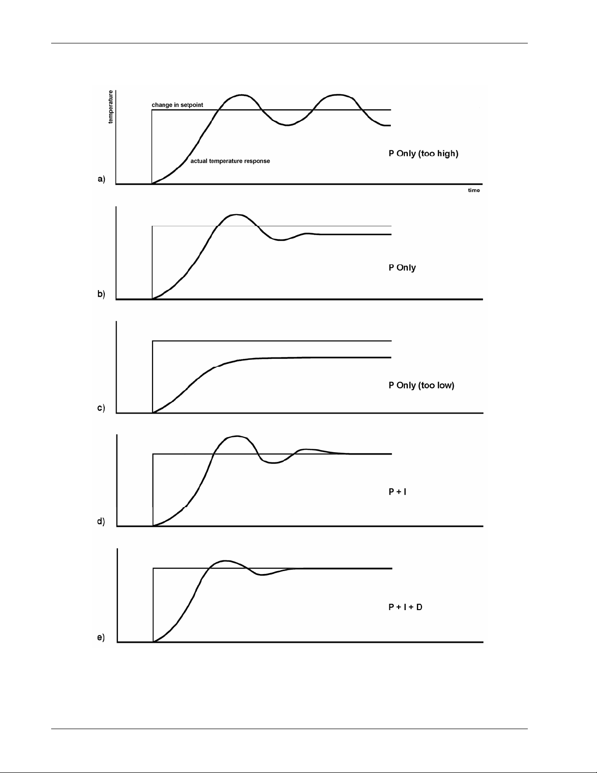
Omega Model CYC325 Temperature Controller User’s Manual
P-CYC325-2-3.bmp
Figure 2-3. Examples of PID Control
2-10 Cooling System Design
Page 31

Omega Model CYC325 Temperature Controller User’s Manual
2.7 MANUAL TUNING
There has been a lot written about tuning closed loop control systems and specifically PID control loops. This section
does not attempt to compete with control theory experts. It describes a few basic rules of thumb to help less experienced
users get started. This technique will not solve every problem, but it has worked for many others in the field. This section
assumes the user has worked through the operation sections of this manual, has a good temperature reading from the
sensor chosen as a control sensor, and is operating Loop 1. It is also a good idea to begin at the center of the temperature
range of the cooling system (not close to its highest or lowest temperature). AutoTune (Section 2.8) is another good
place to begin, and do not forget the power of trial and error.
2.7.1 Setting Heater Range
Setting an appropriate heater output range is an important first part of the tuning process. The heater range should allow
enough heater power to comfortably overcome the cooling power of the cooling system. If the heater range will not
provide enough power, the load will not be able to reach the setpoint temperature. If the range is set too high, the load
may have very large temperature changes that take a long time to settle out. Delicate loads can even be damaged by too
much power.
Often there is little information on the cooling power of the cooling system at the desired setpoint. If this is the case, try
the following: Allow the load to cool completely with the heater off. Set manual heater power output to 50% while in
Open Loop control mode. Turn the heater to the lowest range and write down the temperature rise (if any). Select the
next highest heater range and continue the process until the load warms up to room temperature. Do not leave the system
unattended; the heater may have to be turned off manually to prevent overheating. If the load never reaches room
temperature, some adjustment may be needed in heater resistance or load.
The list of heater range versus load temperature is a good reference for selection the proper heater range. It is common
for systems to require two or more heater ranges for good control over their full temperature. Lower heater ranges are
normally needed for lower temperature. The Model CYC325 is of no use controlling at or below the temperature reached
when the heater was off. Many systems can be tuned to control within a degree or two above that temperature.
2.7.2 Tuning Proportional
The proportional setting is so closely tied to heater range that they can be thought of as fine and coarse adjustments of
the same setting. An appropriate heater range must be known before moving on to the proportional setting.
Begin this part of the tuning process by letting the cooling system cool and stabilize with the heater off. Place the Model
CYC325 in closed loop control mode with manual PID tuning, then turn integral, derivative and manual output settings
off. Enter a setpoint several degrees above the cooling systems lowest temperature. Enter a low proportional setting of
approximately 5 or 10 and then enter the appropriate heater range as described above. The heater display should show a
value greater than zero and less than 100%. The load temperature should stabilize at a temperature below the setpoint.
If the load temperature and heater meter swing rapidly, the heater range may be set too high and should be reduced. Very
slow changes in load temperature that could be described as drifting are an indication of a proportional setting that is too
low (which is addressed in the next step).
Gradually increase the proportional setting by doubling it each time. At each new setting, allow time for the temperature
of the load to stabilize. As the proportional setting is increased, there should be a setting in which the load temperature
begins a sustained and predictable oscillation rising and falling in a consistent period of time. See Figure 2-3(a). The goal
is to find the proportional value in which the oscillation begins, do not turn the setting so high that temperature and
heater output changes become violent.
Record the proportional setting and the amount of time it takes for the load change from one temperature peak to the
next. The time is called the oscillation period of the load. It helps describe the dominant time constant of the load, which
is used in setting integral. If all has gone well, the appropriate proportional setting is one half of the value required for
sustained oscillation. See Figure 2-3(b).
Cooling System Design 2-11
Page 32

Tuning Proportional (Continued)
Omega Model CYC325 Temperature Controller User’s Manual
If the load does not oscillate in a controlled manner, the heater range could be set too low. A constant heater reading of
100% on the display would be an indication of a low range setting. The heater range could also be too high, indicated by
rapid changes in the load temperature or heater output with a proportional setting of less than 5. There are a few systems
that will stabilize and not oscillate with a very high proportional setting and a proper heater range setting. For these
systems, setting a proportional setting of one half of the highest setting is the best choice.
2.7.3 Tuning Integral
When the proportional setting is chosen and the integral is set to zero (off), the Model CYC325 controls the load
temperature below the setpoint. Setting the integral allows the Model CYC325 control algorithm to gradually eliminate
the difference in temperature by integrating the error over time. See Figure 2-3(d). An integral setting that is too low
causes the load to take too long to reach the setpoint. An integral setting that is too high creates instability and can cause
the load temperature to oscillate.
Begin this part of the tuning process with the system controlling in proportional only mode. Use the oscillation period of
the load that was measured above in seconds. Divide 1000 by the period to get the integral setting. Enter the integral
setting into the Model CYC325 and watch the load temperature approach the setpoint. If the temperature does not
stabilize and begins to oscillate around the setpoint, the integral setting is too high and should be reduced by one half. If
the temperature is stable but never reaches the setpoint, the integral setting is too low and should be doubled.
To verify the integral setting, make a few small (2 to 5 degree) changes in setpoint and watch the load temperature react.
Trial and error can help improve the integral setting by optimizing for experimental needs. Faster integrals, for example,
get to the setpoint more quickly at the expense of greater overshoot. In most systems, setpoint changes that raise the
temperature act differently than changes that lower the temperature.
If it was not possible to measure the oscillation period of the load during proportional setting, start with an integral
setting of 20. If the load becomes unstable reduce the setting by half. If the load is stable make a series of small, two to
five degree, changes in the setpoint and watch the load react. Continue to increase the integral setting until the desired
response is achieved.
2.7.4 Tuning Derivative
If an experiment requires frequent changes in setpoint or data taking between changes in the setpoint, derivative should
be considered. See Figure 2-3(e). A derivative setting of zero, off, is recommended when the control system is seldom
changed and data is taken when the load is at steady state.
The derivative setting is entered into the Model CYC325 as a percentage of the integral time constant. The setting range
is
0 – 200% where 100% = ¼ I seconds. Start with a setting of 50 to 100%.
Again, do not be afraid to make some small setpoint changes; halving or doubling this setting to watch the affect. Expect
positive setpoint changes to react differently from negative setpoint changes.
2.8 AUTOTUNING
Choosing appropriate PID control settings can be tedious. Systems can take several minutes to complete a setpoint
change, making it difficult to watch the display for oscillation periods and signs of instability. With the AutoTune
feature, the Model CYC325 automates the tuning process by measuring system characteristics and, along with some
assumptions about typical cryogenic systems, computes setting values for P, I, and D. AutoTune works only with one
control loop at a time and does not set the manual heater power output or heater range. Setting an inappropriate heater
range is potentially dangerous to some loads, so the Model CYC325 does not automate that step of the tuning process.
When the AutoTune mode is selected, the Model CYC325 evaluates the control loop similar to the manual tuning section
described in Section 2.7. One difference is that the Model CYC325 does not initiate changes to control settings or
setpoint for the purpose of tuning. It only gathers data and changes control settings after the user changes the setpoint.
Unexpected or unwanted disturbances to the control system can ruin experimental data being taken by the user.
2-12 Cooling System Design
Page 33

AutoTuning (Continued)
Omega Model CYC325 Temperature Controller User’s Manual
When the user selects a new setpoint, the Model CYC325 logs the change in temperature at the load and the change in
heater output that was required to make the load temperature change. The old control settings are used while data is
being logged, so a good initial guess of settings can improve the efficiency of the AutoTune feature. Once the load
temperature is at or near the new setpoint, the Model CYC325 looks at the logged data to calculate the best P, I, and D
settings values. Those values are then loaded and used as the control parameters so the control loop can stabilize at the
new setpoint. AutoTune does not function during a ramp because the dominant time constant of the load is disguised by
the ramp rate.
The control channel annunciator blinks to indicate that tuning data is being logged. The control channel annunciator
stops blinking when the tuning process is complete. The control channel annunciator will not blink again until the user
changes the setpoint. If AutoTune does not give desired results the first time, make a few small (2 to 5 degree) changes
in setpoint and let the Model CYC325 go until the control channel annunciator stops blinking. In many cases, AutoTune
is able to arrive at a better set of control settings.
There are situations where AutoTune is not the answer. The algorithm can be fooled when cooling systems are very fast,
very slow, have a large thermal lag, or have a nonlinear relationship between heater power and load temperature. If a
load can reach a new setpoint in under 10 seconds (with an appropriate I setting >500), the cooling system is too fast for
AutoTuning. Systems with a very small thermal mass can be this fast. Adding mass is a solution, but is unappealing to
users who need the speed for fast cycle times. Manual tuning is not difficult on these systems because new settings can
be tested very quickly. Some systems are too slow for the AutoTune algorithm. Any system that takes more than 15
minutes to stabilize at a new setpoint is too slow (with an appropriate I setting <5).
Thermal lag can be improved by using the sensor and heater installation techniques discussed above. Lag times up to a
few seconds should be expected; much larger lags can be a problem. System nonlinearity is a problem for both AutoTune
and manual tuning. It is most commonly noticed when controlling near the maximum or minimum temperature of a
temperature control system. It is not uncommon; however, for a user to buy a cryogenic cooling system specifically to
operate near its minimum temperature. If this is the case, try to tune the system at 5 degrees above the minimum
temperature and gradually reduce the setpoint, manually adjusting the control settings with each step. Any time the
mechanical cooling action of a cryogenic refrigerator can be seen as periodic temperature fluctuations, the mass is too
small or temperature too low to AutoTune.
2.9 ZONE TUNING
Once the PID tuning parameters have been chosen for a given setpoint the whole process may have to be done again for
other setpoints significantly far away that have different tuning needs. Trying to remember when to use which set of
tuning parameters can be frustrating. The Model CYC325 has a Zone feature as one of its tuning modes that can help.
To use the Zone feature the user must determine the best tuning parameters for each part of the temperature range of
interest. The parameters are then entered into the Model CYC325 where up to ten zones can be defined with different P,
I, D, heater range, and manual heater settings. A setpoint setting is assigned as the maximum temperature for that zone.
The minimum temperature for a zone is the setpoint for the previous zone, 0 K is the starting point for the first zone.
When Zone tuning is on, each time the setpoint changes, appropriate control parameters are chosen automatically.
Control parameters can be determined manually or by using the AutoTune feature. AutoTune is a good way to determine
a set of tuning parameters for the control system that can then be entered as zones. Once the parameters are chosen,
AutoTune is turned off and zone tuning takes over.
Zone tuning has advantages over AutoTune during normal operation. When a new setpoint is set, the zone tuning
automatically sets the appropriate control parameters for the destination. Approach to the new setpoint is controlled with
the best parameters. AutoTune, on the other hand, is not able to learn enough about the system to change the control
parameters until after the temperature gets near or to the new setpoint. Approach to the new setpoint is controlled with
the old parameters because they are the best available.
Cooling System Design 2-13
Page 34

Omega Model CYC325 Temperature Controller User’s Manual
This Page Intentionally Left Blank
2-14 Cooling System Design
Page 35

Omega Model CYC325 Temperature Controller User’s Manual
CHAPTER 3
INSTALLATION
3.0 GENERAL
This chapter provides general installation instructions for the Model CYC325 temperature controller. Please read this
entire chapter before installing the instrument and powering it on to ensure the best possible performance and maintain
operator safety. For instrument operating instructions refer to Chapter 4 and Chapter 5. For computer interface
installation and operation refer to Chapter 6.
3.1 INSPECTION AND UNPACKING
Inspect shipping containers for external damage before opening them. Photograph any container that has significant
damage before opening it. If there is visible damage to the contents of the container contact the shipping company and
Omega immediately, preferably within 5 days of receipt of goods. Keep all damaged shipping materials and contents
until instructed to either return or discard them.
Open the shipping container and keep the container and shipping materials until all contents have been accounted for.
Check off each item on the packing list as it is unpacked. Instruments themselves may be shipped as several parts. The
items included with the Model CYC325 are listed below. Contact Omega immediately if there is a shortage of parts or
accessories. Omega is not responsible for any missing items if not notified within 60 days of shipment.
Inspect all items for both visible and hidden damage that occurred during shipment. If damage is found, contact Omega
immediately for instructions on how to file a proper insurance claim. Omega products are insured against damage during
shipment but a timely claim must be filed before Omega will take further action. Procedures vary slightly with shipping
companies. Keep all shipping materials and damaged contents until instructed to either return or discard them.
If the instrument must be returned for recalibration, replacement or repair, a Return Authorization (RA) number must be
obtained from a factory representative before it is returned. The Omega RA procedure is given in Section 8.2.
Items Included with Model CYC325 Temperature Controller:
1 Model CYC325 instrument
1 Model CYC325 user’s manual
2 Sensor input mating connector, 6-pin DIN
1 Heater output connector, dual banana, for Loop 1 heater out
1 Terminal block mating connector, 2-pin terminal block, for Loop 2 heater out
1 Line power cord
1 Line power cord for alternative voltage*
*
Included only when purchased with VAC-120-ALL power option.
Installation 3-1
Page 36
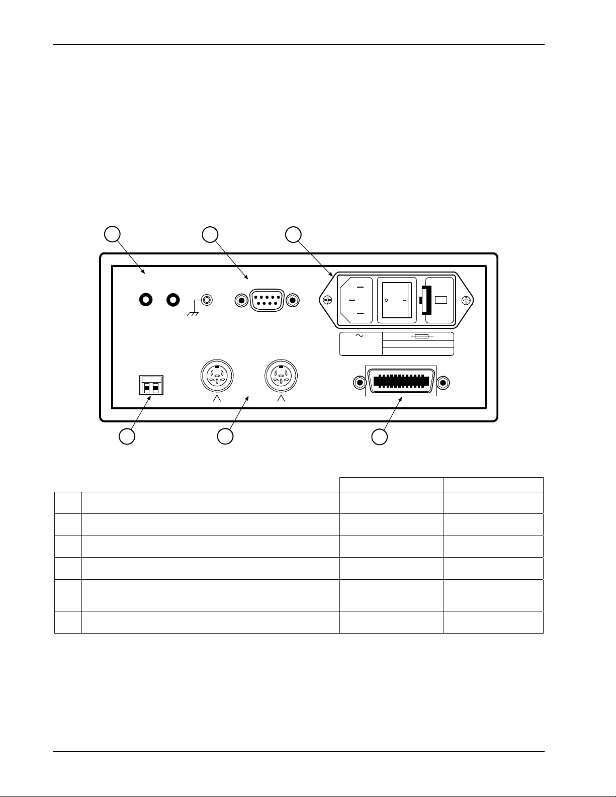
Omega Model CYC325 Temperature Controller User’s Manual
3.2 REAR PANEL DEFINITION
This section provides a description of the Model CYC325 rear panel connections. The rear panel consists of the line
input assembly, RS-232 connector, INPUT A and B sensor input connectors, IEEE-488 INTERFACE connector, and
LOOP 1 and 2 HEATER OUT connectors. Please read the entire chapter before performing the initial setup and system
checkout procedure in Section 3.7. Rear panel connector pin-out details are provided in Section 8.7.
CAUTION: Verify AC line voltage shown in the fuse holder window is appropriate for the intended
AC power input. Also remove and verify the proper fuse is installed before plugging in and
turning on the instrument.
CAUTION: Always turn off the instrument before making any rear panel connections. This is especially
critical when making sensor-to-instrument connections.
1
LOOP 1
HEATER OUT
HI
LO
GND
RS-232 (D TE)
32
120
WARNING
NO USER SERVICEABLE
PARTS INSIDE. REFER
SERVICING TO TRAINED
SERVICE PERSONNEL
LOOP 2
HEATER OUT
LO
HI
6
INPUT A
I+
V+
! !
5
INPUT B
I–
I+
V–
V+
I–
V–
100/120/220/240 V
–10% +6% Voltage
50-60 Hz 150 VA MAX
IEEE-488 INTERFACE
4
100/120V
220/240V
1.6 A T 250V
1.6 A T 250V
5×20mm
5×20mm
F-CYC325-3-1.wmf
Loop 1 Heater Out Banana Jack and Ground Screw Terminal Section 3.6 Figure 8-4
c
RS-232 (DTE) 9-pin D-Style Connector Section 6.2.1 Figure 8-6
d
Line Input Assembly Section 3.3 Figure 8-2
e
IEEE-488 INTERFACE Connector Section 8.7.2 Figure 8-7
f
INPUT A and INPUT B Sensor (or Thermocouple)
g
Input Connectors
Description Details
Sections 3.4 and 3.5 Figure 8-3 and 3-4
Loop 2 Heater Out Section 3.6 Figure 8-5
h
Figure 3-1. Model CYC325 Rear Panel
3-2 Installation
Page 37
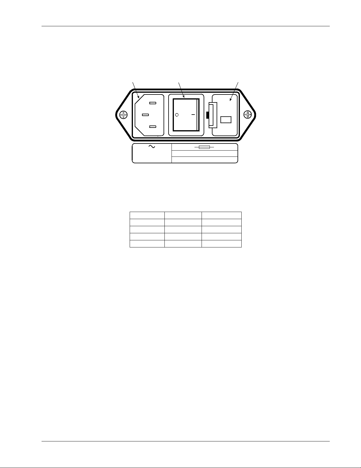
Omega Model CYC325 Temperature Controller User’s Manual
3.3 LINE INPUT ASSEMBLY
This section describes how to properly connect the Model CYC325 to line power. Please follow these instructions
carefully to ensure proper operation of the instrument and the safety of operators.
Line Cord
Input
Power Switch
O = Off, l = On
Fuse
Drawer
120
100/120/220/240 V
–10% +6% Voltage
50-60 Hz 85 VA MAX
F-CYC325-3-2.wmf
100/120V
220/240V
1.6 A T 250 V
1.6 A T 250 V
5×20mm
5×20mm
Figure 3-2. Line Input Assembly
3.3.1 Line Voltage
The Model CYC325 has four different AC line voltages configurations so that it can be operated from line power
anywhere in the world. The nominal voltage and voltage range of each configuration is shown below. (The
recommended setting for 230 V operation is 240 V.)
Nominal Minimum Maximum
100 V 90 V 106 V
120 V 108 V 127 V
220 V 198 V 233 V
240 V 216 V 254 V
Verify that the AC line voltage indicator in the fuse drawer window shows the appropriate AC line voltage before
turning the instrument on. The instrument may be damaged if turned on with the wrong voltage selected. Instructions for
changing the line voltage configuration are given in Section 8.4.
3.3.2 Line Fuse and Fuse Holder
The line fuse is an important safety feature of the Model CYC325. If a fuse ever fails, it is important to replace it with
the value and type indicated on the rear panel for the line voltage setting. The letter T on the fuse rating indicates that the
instrument requires a time-delay or slow-blow fuse. Fuse values should be verified any time line voltage configuration is
changed. Instructions for changing and verifying a line fuse are given in Section 8.5.
3.3.3 Power Cord
The Model CYC325 includes a 3-conductor power cord that mates with the IEC 320-C14 line cord receptacle. Line
voltage is present on the two outside conductors and the center conductor is a safety ground. The safety ground attaches
to the instrument chassis and protects the user in case of a component failure. A CE-approved power cord is included
with instruments shipped to Europe; a domestic power cord is included with all other instruments (unless otherwise
specified when ordered). Always plug the power cord into a properly grounded receptacle to ensure safe instrument
operation.
The delicate nature of measurements being taken with this instrument may necessitate additional grounding including
ground strapping of the instrument chassis. In these cases the operator’s safety should remain the highest priority and
low impedance from the instrument chassis to safety ground should always be maintained.
3.3.4 Power Switch
The power switch is part of the line input assembly on the rear panel of the Model CYC325 and turns line power to the
instrument On and Off. When the circle is depressed, power is Off. When the line is depressed, power is On.
Installation 3-3
Page 38
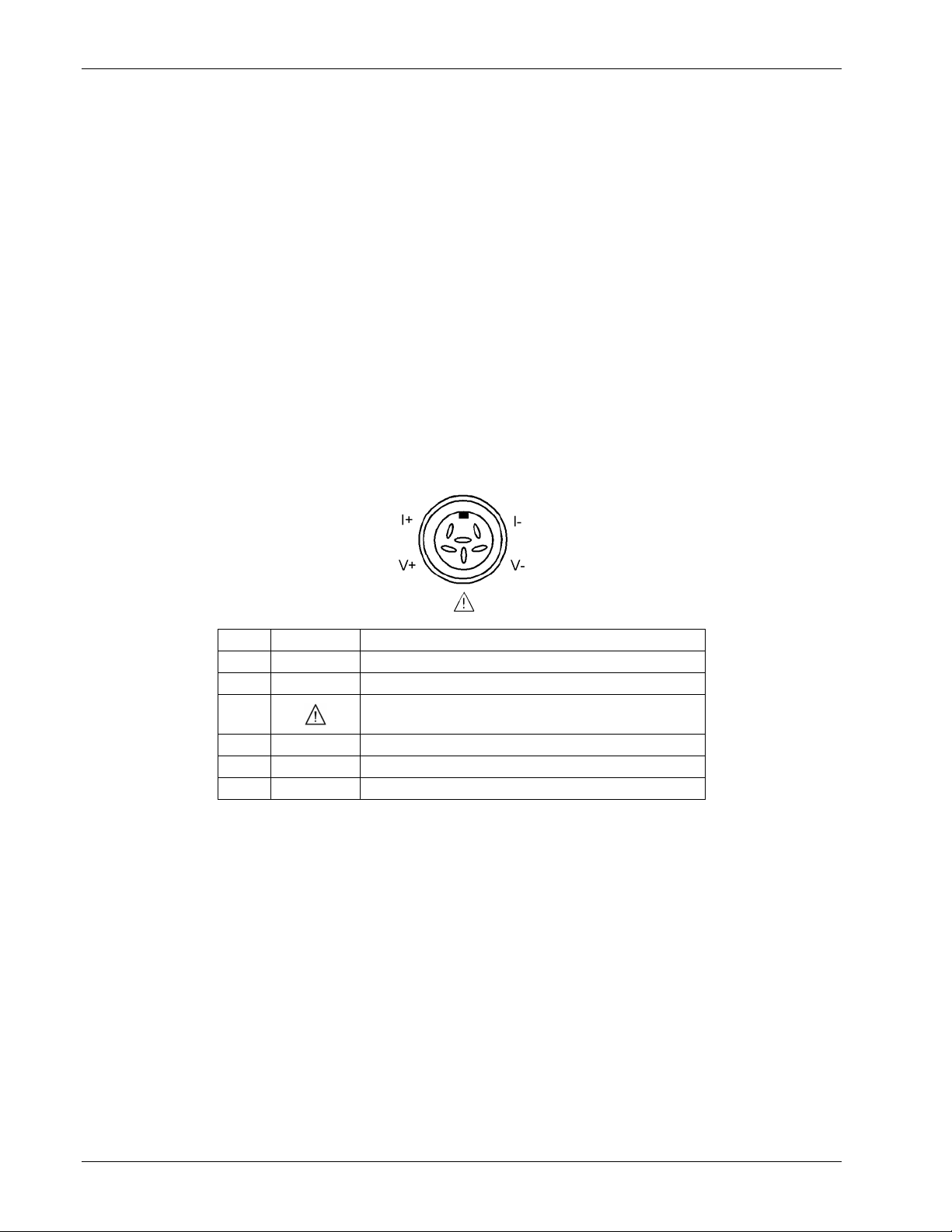
Omega Model CYC325 Temperature Controller User’s Manual
3.4 DIODE/RESISTOR SENSOR INPUTS
This section details how to connect diode and resistor sensors to the Model CYC325 inputs. Refer to Section 4.4 to
configure the inputs. The optional thermocouple input is described in Section 3.5.
3.4.1 Sensor Input Connector and Pinout
The input connectors are 6-pin DIN 45322 sockets. The sensor output pins are defined in Figure 3-3. Two mating
connectors (6-pin DIN plugs) are included in the connector kit shipped with the instrument. These are common
connectors, so additional mating connectors can be purchased from local electronics suppliers. They can also be ordered
from Omega (P/N 106-233).
NOTE: Pin 3 should not be used for new installations. However, to match existing Model 321, Model 330, or
Model 340 connector wiring, the definition of Pin 3 may be changed with a jumper. See Figure 8-8
for jumper location.
To provide compatibility with sensor input connectors that have been wired for the Omega Model CYC321 temperature
controller, Jumper 4 (for Input A) and Jumper 7 (for Input B) are used to select the function of Pin 3 of the connectors.
The Model CYC321 provides a constant 1 mA sensor excitation current on Pin 3 and 10 µA current on Pin 5. If the
sensor being used was wired for use with a Model CYC321, the jumper should be placed in the 321/ 330 position
(factory default). This provides the output current selected via the front panel input setup function on both Pins 5 and 3.
Pin Symbol Description
1 I– – Current
2 V– – Voltage
3
+1 mA – Model CYC321/CYC330 Configuration
Shield – Model CYC340 Configuration
4 V+ + Voltage
5 I+ + Current
6 None Shield
Figure 3-3. Diode/Resistor Input Connector
3.4.2 Sensor Lead Cable
The sensor lead cable used outside the cooling system can be much different from what is used inside. Between the
instrument and vacuum shroud, error and noise pick up, not heat leak, need to be minimized. Larger conductor, 22 to
28 AWG stranded copper wire is recommended because it has low resistance yet remains flexible when several wires are
bundled in a cable. The arrangement of wires in a cable is also important. For best results, voltage leads, V+ and V–
should be twisted together and current leads I+ and I– should be twisted together. The twisted pairs of voltage and
current leads should then be covered with a braided or foil shield that is connected to the shield pin of the instrument.
This type of cable is available through local electronics suppliers. Instrument specifications are given assuming 10 ft of
sensor cable. Longer cables, 100 ft or more, can be used but environmental conditions may degrade accuracy and noise
specifications. Refer to Section 2.3.6 for information about wiring inside the cryostat.
3-4 Installation
Page 39
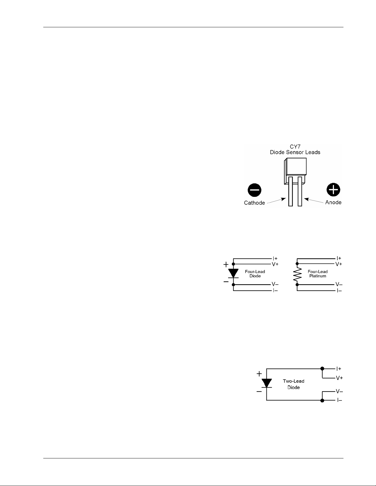
Omega Model CYC325 Temperature Controller User’s Manual
3.4.3 Grounding and Shielding Sensor Leads
The sensor inputs are isolated from earth ground to reduce the amount of earth ground referenced noise that is present on
the measurement leads. This isolation can be defeated by connecting sensor leads to earth ground on the chassis of the
instrument or in the cooling system. If one sensor lead must be grounded, ground only one lead and ground it in only one
place. Grounding leads on more than one sensor prevents the sensor excitation current sources from operating.
Shielding the sensor lead cable is important to keep external noise from entering the measurement. A shield is most
effective when it is near the measurement potential so the Model CYC325 offers a shield that stays close to the
measurement. The shield of the sensor cable should be connected to the shield pin of the input connector. It should not
be terminated at the opposite end of the cable. The shield should not be connected to earth ground on the instrument
chassis or in the cooling system.
NOTE: The shell of the connector is in contact with the chassis so the cable shield should never touch the
outer shell of the connector.
3.4.4 Sensor Polarity
Omega sensors are shipped with instructions that indicate which sensor leads
are which. It is important to follow these instructions for plus and minus leads
(polarity) as well as voltage and current when applicable. Diode sensors do not
operate in the wrong polarity. They look like an open circuit to the instrument.
Two lead resistors can operate with any lead arrangement and the sensor
instructions may not specify. Four-lead resistors can be more dependent on
lead arrangement. Follow any specified lead assignment for four lead resistors.
Mixing leads could give a reading that appears correct but is not the most accurate.
3.4.5 Four-Lead Sensor Measurement
All sensors, including both two-lead and four-lead can be measured with a four-lead technique. The purpose of a fourlead measurement is to eliminate the effect of lead resistance on the measurement. If it is not taken out, lead resistance is
a direct error when measuring a sensor.
In a four-lead measurement, current leads and voltage leads are run
separately up to the sensor. With separate leads there is little current
in the voltage leads so their resistance does not enter into the
measurement. Resistance in the current leads will not change the
measurement as long as the voltage compliance of the current
source is not reached. When two-lead sensors are used in four-lead
measurements, the short leads on the sensor have an insignificant resistance.
3.4.6 Two-Lead Sensor Measurement
There are times when crowding in a cryogenic system forces users to read sensors in a two lead configuration because
there are not enough feedthroughs or room for lead wires. If this is the case, plus voltage to plus current and minus
voltage to minus current leads are attached at the back of the instrument or at the vacuum feedthrough.
The error in a resistive measurement is the resistance of the lead wire run with current and voltage together. If the leads
contribute 2 or 3 Ω to a 10 kΩ reading, the error can probably be tolerated. When measuring voltage for diode sensors
the error in voltage can be calculated as the lead resistance times the current,
typically 10 µA. For example: a 10 Ω lead resistance times 10 µA results in a
0.1 mV error in voltage. Given the sensitivity of a silicon diode at 4.2 K, the error
in temperature would be only 3 mK. At 77 K the sensitivity of a silicon diode is
lower so the error would be close to 50 mK. Again, this may not be a problem for
every user.
Installation 3-5
Page 40
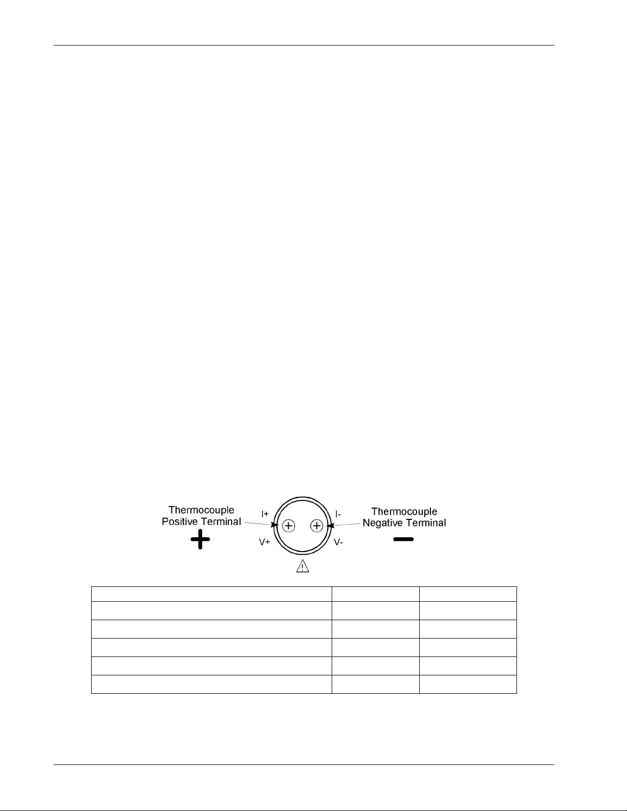
Omega Model CYC325 Temperature Controller User’s Manual
3.4.7 Lowering Measurement Noise
Good instrument hardware setup technique is one of the least expensive ways to reduce measurement noise. The
suggestions fall into two categories: (1) Do not let noise from the outside enter into the measurement, and (2) Let the
instrument isolation and other hardware features work to their best advantage. Here are some further suggestions:
• Use four-lead measurement whenever possible.
• Do not connect sensor leads to chassis or earth ground.
• If sensor leads must be grounded, ground leads on only one sensor.
• Use twisted shielded cable outside the cooling system.
• Attach the shield pin on the sensor connector to the cable shield.
• Do not attach the cable shield at the other end of the cable, not even to ground.
• Run different inputs and outputs in their own shielded cable.
• Use twisted wire inside the cooling system.
• Use similar technique for heater leads.
• Use a grounded receptacle for the instrument power cord.
• Consider ground strapping the instrument chassis to other instruments or computers.
3.5 THERMOCO UPLE SENSOR INPUTS (Model CYC325-TX Only)
The information in this section is for a Model CYC325 configured at the factory with one or two thermocouple sensor
inputs: Model CYC325-T1 or -T2. Sensor connection is important when using thermocouples because the measured
signal is small. Many measurement errors can be avoided with proper sensor installation.
CAUTION: Do not leave thermocouple inputs unconnected. Short inputs when not in use.
3.5.1 Sensor Input Terminals
Attach sensor leads to the screws on the off-white ceramic terminal blocks. Each block has two screw terminals; one
positive (on the I+
/ V+ side of the connector), one negative (on the I– / V– side of the connector). See Figure 3-4.
The current and voltage references silkscreened on the back panel are for the diode/resistor connectors. For
thermocouples, the positive (+) wire goes to the left-side terminal and the negative (–) wire to the right-side terminal.
Remove all insulation then tighten the screws on the thermocouple wires. Keep the ceramic terminal blocks away from
heat sources including sunlight and shield them from fans or room drafts.
Common Thermocouple Polarities Positive (+) Negative (–)
Type K (Nickel-Chromium vs. Nickel-Aluminum) Chromel (YEL) Alumel (RED)
Type E (Nickel-Chromium vs. Copper-Nickel) Chromel (PUR) Constantan (RED)
Type T (Copper vs. Copper-Nickel) Copper (BLU) Constantan (RED)
Chromel-AuFe 0.03% Chromel Gold
Chromel-AuFe 0.07% Chromel Gold
Figure 3-4. Thermocouple Input Definition and Common Connector Polarities
3-6 Installation
Page 41

Omega Model CYC325 Temperature Controller User’s Manual
3.5.2 Thermocouple Installation
Thermocouples are commonly used in high-temperature applications. Cryogenic use of thermocouples offers some
unique challenges. A general installation guideline is provided in Section 2.3. Consider the following when using
thermocouples at low temperatures:
• Thermocouple wire is generally more thermally conductive than other sensor lead wire. Smaller gauge wire and more
heat sinking may be needed to prevent leads from heating the sample.
• Attaching lead wires and passing through vacuum-tight connectors are often necessary in cryogenic systems.
Remember, the thermocouple wire is the sensor; any time it joins or contacts other metal, there is potential for error.
• Temperature verification and calibration of room temperature compensation is difficult after the sensor is installed.
When possible, keep a piece of scrap wire from each installation for future use.
3.5.3 Grounding and Shielding
For lowest measurement noise, do not ground thermocouple sensors. The instrument operates with more noise if one of
the thermocouples is grounded. Grounding both thermocouples is not recommended. The instrument does not offer a
shield connection on the terminal block. Twisting the thermocouple wires helps reject noise. If shielding is necessary,
extend the shield from the oven or cryostat to cover the thermocouple wire, but do not attach the shield to the instrument.
3.6 HEATER OUTPUT SETUP
The following section covers the heater wiring from the vacuum shroud to the instrument for both control loop outputs.
Specifications are detailed in Section 1.2. For help on choosing and installing an appropriate resistive heater, refer to
Section 2.4.
3.6.1 Loop 1 Output
Of the two Model CYC325 control loops, Loop 1 is considered the primary loop because it is capable of driving 25 W of
heater power. The heater output for Loop 1 is a traditional control output for a cryogenic temperature controller. It is a
variable DC current source with software settable ranges and limits. The heater is configurable for optimization using
either a 25 Ω or a 50 Ω heater resistance. At the 25 Ω setting, the maximum heater output current is 1 A and the
compliance voltage is 25 V. At the 50 Ω setting, the maximum heater output current is 0.71 A and the compliance
voltage is 35.4 V. Heater power is applied in one of two ranges: Low or High. At the Low range setting, the Loop 1
heater will output 10% of the High range power.
3.6.2 Loop 1 Heater Output Connector
A dual banana jack on the rear panel of the instrument is used for connecting
wires to the Loop 1 heater. A standard dual banana plug mating connector is
included in the connector kit shipped with the instrument. This is a common
jack and additional mating connectors can be purchased from local electronic
suppliers, or from Omega (P/N 106-009). The heater is connected between
the HI and LO terminals. The ground terminal is reserved for shielding the
heater leads when necessary.
3.6.3 Loop 1 Heater Output Wiring
Heater output current is what determines the size (gauge) of wire needed to connect the heater. The maximum current
that can be sourced from the Loop 1 heater output is 1 A. When less current is needed to power a cooling system, it can
be limited with range settings.
When setting up a temperature control system, the lead wire for the heater must be capable of carrying a continuous
current that is greater than the maximum current. Wire manufacturers recommend 30 AWG or larger wire to carry 1 A of
current, but there is little advantage in using wire smaller than 20 to 22 AWG outside the cryostat. Inside the cryostat,
smaller gauge wire is often desirable.
The use of twisted heater leads is recommended. Large changes in heater current can induce noise in measurement leads
and twisting reduces the effect. Omega also recommends running heater leads in a separate cable from the measurement
leads to further reduce interaction.
Installation 3-7
Page 42

Loop 1 Heater Output Wiring (continued)
Omega Model CYC325 Temperature Controller User’s Manual
There is a chassis ground point at the rear panel of the instrument for shielding the heater cable. The cable shield can be
tied to this point using a #4 spade or ring connector. The shield should not be connected at the opposite end of the cable
and should never be tied to the heater output leads.
For best noise performance, do not connect the resistive heater or its leads to ground. Also avoid connecting heater leads
to sensor leads or any other instrument inputs or outputs.
3.6.4 Loop 1 Heater Output Noise
The heater output circuitry in the Model CYC325 must be capable of sourcing 25 W of power. This type of circuitry can
generate some electrical noise. The Model CYC325 was designed to generate as little noise as possible but even noise
that is a small percentage of the output voltage or current can be too much when sensitive measurements are being made
near by. If the Model CYC325 heater leads are too noisy and the above wiring techniques do not help, Omega offers the
Model 3003 Heater Output Conditioner that may help. Refer to Section 7.4.
3.6.5 Loop 2 Output
The Model CYC325 has a second control loop called Loop 2. Loop 2 is an auxiliary control loop with the capability of
powering a small sample heater, or controlling a larger, programmable heater power supply. Loop 2 has a different
output from Loop 1; it uses analog voltage output as its actuator. It is a variable DC voltage source with an output range
from 0 V to +10 V. The output can source up to 200 mA of current providing a maximum of 2 W with a 50 Ω heater at
the 50 Ω setting. The output voltage range is 0 V to +5 V when set to the 25 Ω setting, providing a maximum power of
1 W into a 25 Ω heater.
3.6.6 Loop 2 Output Resistance
The power delivered by the Loop 2 output is calculated as: P = V
2
/ R
. The output is rated for no more than 200 mA
heater
of current and has a built in current limit. For the maximum 2 W output power, use a 50 Ω resistive heater with a power
rating greater than 2 W. A 25 Ω heater can be used to provide 1 W of power. The 25 Ω setting for Loop 2 changes the
output voltage range to allow for control over the entire range of output. Using a 25 Ω heater at the 50 Ω setting would
still provide 1 W of power, but the maximum power will be reached at a setting of about 50%, at which point the
200 mA current limit will begin to limit output power and could cause temperature control instability.
3.6.7 Loop 2 Output Connector
The connector for the Loop 2 output is a 2 pin detachable terminal block. See Figure 8-5. A twisted pair of small gauge
wires is recommended.
3.6.8 Loop 2 Heater Protection
The output is short protected so the instrument is not harmed if the heater resistance is too small. It is not recommended
because control over the full output voltage range is lost when in power limit mode. The user must be careful to build a
robust system and account for the voltage range and power up state of the control output.
3.6.9 Boosting Output Power
There are temperature control systems that require more power than the Model CYC325 can provide. An auxiliary DC
power supply can be used to boost the output of the Model CYC325. Programmable power supplies are available that
use a low current programming voltage as an input to control a high current voltage output. Loop 2 provides an ideal
programming voltage for an auxiliary power supply.
The only drawback to using the Loop 2 output to program an auxiliary supply is that it has only one heater range.
Although the heater resistance setting for Loop 2 does provide two different voltage scaling options (25 Ω setting: 0 to
+5 V, 50 Ω setting: 0 to +10 V), the output resolution of each setting is the same. The heater output for Loop 1 has two
ranges. Using the Low range will improve resolution, but the Loop 1 output is in current, not voltage. To use Loop 1 to
program a larger power supply, a programming resistor can be placed across the heater output to produce a programming
voltage. The programming voltage is related to output current by:
V
program
= R
program
× I
output
.
3-8 Installation
Page 43

Omega Model CYC325 Temperature Controller User’s Manual
Boosting Output Power (Continued)
The resistor must be chosen to convert a full scale current from the highest heater output range being used to the full
scale programming voltage of the auxiliary supply. For example, if the auxiliary supply has a full scale programming
voltage of 10 V and the maximum current for the highest heater output range being used is 0.3 A the programming
resistor should be 10 V / 0.3 A = 33 Ω. The programming resistor must be rated for the power being dissipated in it,
which is:
Power = I
output
2
× R
program
or 3 W. The “Low” heater output range can be selected to reduce the power dissipated in the programming resistor.
3.7 INITIAL SETUP AND SYSTEM CHECKOUT PROCEDURE
The following is an initial instrument setup and checkout procedure. The intent is to verify basic operation of the unit
before beginning use for measurements. The procedure assumes a setup with two Omega CY7 silicon diode sensors, one
control loop, a single 50 Ω heater, all readings in kelvin, and running in a liquid nitrogen environment.
CAUTION: Check the power source for proper voltage before connecting the line cord to the
Model CYC325. Also check the line voltage setting in the window in the fuse drawer.
Damage to the unit may occur if connected to improper voltage.
1. Check the power source for proper voltage. The Model CYC325 operates with 100, 120, 220, or 240 (+6%, –10%)
AC input voltage.
2. Check the window in the fuse drawer for proper voltage setting. If incorrect, refer to Section 8.4.
3. Ensure the power switch is in the off (O) position.
CAUTION: The sensor must be connected to the rear of the unit before applying power to the
temperature controller. Damage to the sensor may occur if connected with the power on.
4. Verify the sensor installation in the liquid nitrogen environment. Then plug the control sensor connector in INPUT
A and the sample sensor connector in INPUT B. Details of sensor hardware connections are detailed in Section 3.4.
5. Connect the heater to the banana jacks labeled HEATER OUTPUT. A 50 Ω heater allows the maximum power
output of 25 W if the heater resistance setting is set to 50 Ω. A 25 Ω heater allows the maximum power output of
25 W if the heater resistance setting is set to 25 Ω. Details of heater installation are in Sections 2.4 and 3.6.
6. Ensure any other rear panel connections are connected before applying power to the unit. This includes the RS-232
(Section 6.2.1) and IEEE-488 (Section 8.7.2) connectors.
7. Plug the line cord into a receptacle.
8. Turn the power switch to the on (l) position. The front panel will briefly display the following.
9. The typical display shown below will now appear.
À− 77.35½− Á− 77.35½
 −0.000½−−−−0%−Off
The front panel display is divided into four areas. The default display settings place the Sensor A reading in the upper
left, the Sensor B reading in the upper right, the Setpoint in the lower left, and the heater output of Loop 1 (in percent) in
the lower right. All temperature readings are in kelvin. Each of these display areas is individually configurable by
pressing the Display Format key and following the instructions in Section 4.3.
Installation 3-9
Page 44

Initial Setup and System Checkout Procedure (Continued)
Omega Model CYC325 Temperature Controller User’s Manual
NOTE: For rated accuracy, the instrument should warm up for at least 30 minutes.
10. The default input settings are “Silicon Diodes” on Inputs A and B, with Input A controlling using the “Curve 01
CY7.” These settings can be verified by pressing the Input Setup key and following the instructions in Section 4.4.
11. The default control mode is “Manual PID” where the Proportional, Integral, and Derivative (PID) settings are
entered by the user. The default settings are P = 50, I = 20, and D = 0. These settings can be verified and/or adjusted
by pressing the PID/MHP key and following the instructions in Section 4.8.
12. For an experiment running at liquid nitrogen temperature, a setpoint of 77 K is good for testing purposes. Press
the Setpoint key. Press the “7” key twice, then press the Enter key. Details of setpoint setting are discussed in
Section 4.11.
À− 77.35½− Á− 75.35½
 77.000½−−−−0%−Off
13. The default setting for the heater is “Off.” To turn the heater on, press the Heater Range key. Press the s or t key
until “Low” is displayed. Press the Enter key. Depending on your actual setup, you may need to apply more current
to the heater, which is accomplished by selecting the “High” range. Details of heater settings are discussed in
Section 4.13.
À− 77.05½− Á− 75.10½
 77.000½−−−50%−Low
NOTE: If any problems appear, immediately press the Heater Off key. If any error messages are displayed,
refer to Section 8.11 for details.
The Model CYC325 should now be controlling the temperature in the experimental setup at the setpoint temperature.
Once this initial checkout procedure is successfully completed, the unit is ready for normal operation. We recommend all
users thoroughly read Chapter 4 – Operation before attempting to use the Model CYC325 in an actual experiment or
application.
3-10 Installation
Page 45
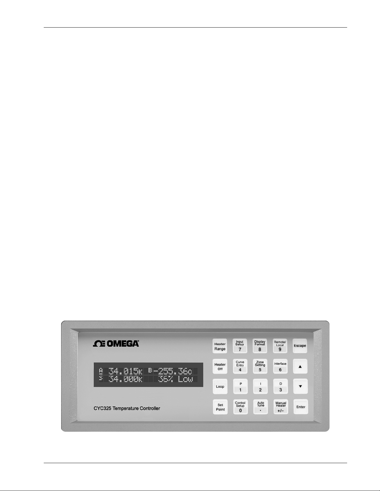
Omega Model CYC325 Temperature Controller User’s Manual
CHAPTER 4
OPERATION
4.0 GENERAL
This chapter provides instructions for the general operating features of the Model CYC325 temperature controller.
Advanced operation is in Chapter 5. Computer interface instructions are in Chapter 6.
4.1 FRONT PANEL DESCRIPTION
This section provides a description of the front panel controls and indicators for the Model CYC325.
4.1.1 Keypad Definitions
An abbreviated description of each key is provided as follows. A more detailed description of each function is provided
in subsequent sections. See Figure 4-1.
AutoTune Allows selection of closed loop tuning mode: AutoTune PID, PI, P, Manual PID, or Zone for the
currently selected loop. Refer to Section 4.9.
Loop Toggles the front panel display and key functions between Loop 1 and 2. Operates with Control Setup,
Setpoint, PID/MHP, Zone Settings, AutoTune, Heater Range, and Heater Off. Refer to Section 4.6.1.
Heater Range For Loop 1, allows selection of High (25 W) or Low (2.5 W) heater range. For Loop 2, allows
selection of Heater On/Off. Refer to Section 4.13.
Heater Off Turns the heater off for Loop 1 or turns the control output off for Loop 2. Refer to Section 4.13.
Control Setup Allows selection of control input, setpoint units, closed or open loop control mode, power up enable,
display of heater output units, setpoint ramp enable, ramp rate for the currently selected loop, and
heater resistance. Refer to Section 4.7 for control setup and Section 4.12 for ramp feature.
Setpoint Allows entry of control setpoint for the currently selected loop. Refer to Section 4.11. A discussion of
the ramp feature is provided in Section 4.12.
Zone Settings Allows entry of up to 10 temperature control zones of customer-entered PID settings and Heater
Ranges for the currently selected loop. Refer to Section 4.10.
CYC325-Front.bmp
Figure 4-1. Model CYC325 Front Panel
Operation 4-1
Page 46

Keypad Definitions (Continued)
Omega Model CYC325 Temperature Controller User’s Manual
P Allows manual adjustment of the Proportional control parameter for the currently selected loop. Refer
to Section 4.8.1.
I Allows manual adjustment of the Integral control parameter for the currently selected loop. Refer to
Section 4.8.2.
D Allows manual adjustment of the Derivative control parameter for the currently selected loop. Refer to
Section 4.8.3.
Manual Heater Allows adjustment of the Manual Heater Power setting. Refer to Section 4.8.4.
Input Setup Allows selection of sensor input type and curve. Refer to Section 4.4 for sensor input setup and Section
4.5 for curve selection.
Curve Entry Allows entry of up to fifteen 200-point CalCurves™ or user curves and SoftCal™. Refer to Chapter 5
– Advanced Operation, Section 5.2 Front Panel Curve Entry Operations.
Display Format Allows the user to configure the display and select the units or other source of the readings. Refer to
Sections 4.1.4 and 4.3.
Remote/Local Sets remote or local operation: Remote refers to operation is via IEEE-488 interface; Local refers to
operation via the front panel. Refer to Section 4.16.
Interface Sets the baud rate of the serial interface and IEEE-488 address and terminators. Refer to Section 4.17.
s Serves two functions: chooses between parameters during setting operations and to increment a
numerical parameter value.
t Serves two functions: chooses between parameters during setting operations and decrements numerical
parameter value.
Escape Terminates a setting function without changing the existing parameter value. Press and hold to reset
instrument to default values. Refer to Section 4.18.
Enter Completes setting functions and returns to normal operation. Press and hold to lock or unlock keypad.
Refer to Section 4.15.
0
– 9, +/–, . Used for entry of numeric data. Includes a key to toggle plus (+) or minus (–), and a key for entry of a
decimal point. Refer to Section 4.1.3.
4.1.2 Annunciators
Display annunciators are listed as follows:
A or A ... Sensor Input A
B or B
.... Sensor Input B
S ............ Setpoint
K.........Temperature in kelvin
C......... Temperature in degrees Celsius
V.........Sensor units of volts
Ω ......... Sensor units of ohms
mV....... Sensor units of millivolts
R.......... Remote
If a displayed sensor input channel is being used to control the currently selected Loop, the display annunciator for that
sensor input will be underlined. Refer to Section 4.4.
4.1.3 General Keypad Operation
There are three basic keypad operations: Direct Operation, Setting Selection, and Data Entry.
Direct Operation. The key function occurs as soon as the key is pressed, e.g., Loop, Heater Off, and Remote/Local.
Setting Selection. Allows the user to select from a list of values. During a selection sequence the s or t key are used to
select a parameter value. After a selection is made the Enter key is pressed to make the change and advance to the next
setting, or the Escape key is pressed to return to the normal display without changing the present setting. The instrument
retains any values entered prior to pressing the Escape key. Some selections are made immediately after pressing a
4-2 Operation
Page 47
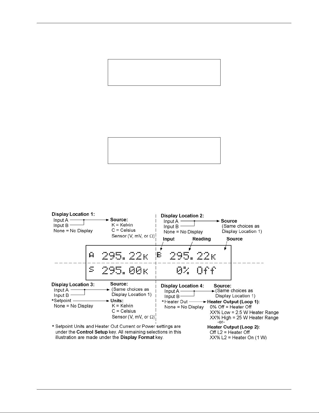
General Keypad Operation (Continued)
Omega Model CYC325 Temperature Controller User’s Manual
function key; like Heater Range. Most are part of a string of settings. Setting selections always include the
“Select for ... st” display, a sample of which is shown below.
Select for Disp 1 °®
Display Input A
Data Entry. Allows the user to enter number data using the data entry keys. Data entry keys include the numbers
0 – 9, +/–, and decimal point. Proportional control parameter is an example of a parameter that requires data entry. During
a data entry sequence use the data entry keys to enter the number value, press the Enter key to accept the new data and
advance to the next setting. Press the Escape key once to clear the entry, twice to return to the normal display. Most data
entry operations are combined with other settings and grouped under a function key. Temperature or sensor unit
parameters have the same setting resolution as the display resolution for their corresponding readings. Data entry always
includes the “Enter for ...” display, a sample of which is shown below.
Enter for Loop 1
Prop (P) 50.000
4.1.4 Display Definition
In normal operation, the 2-row by 20 character LCD display is divided into four user-configurable areas that can provide
temperature readings, setpoint display, and heater status. Other information is displayed when using the various functions
on the keypad. See Figure 4-2.
C-CYC325-4-2.bmp
Figure 4-2. Display Definition
Operation 4-3
Page 48
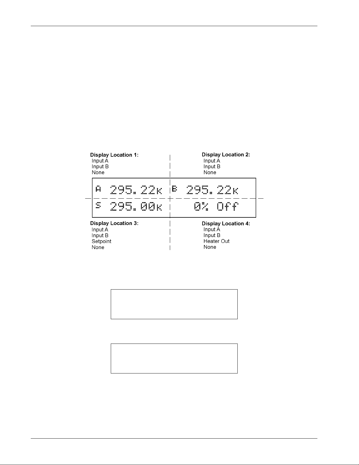
Omega Model CYC325 Temperature Controller User’s Manual
4.2 TURNING POWER ON
After verifying line voltage (Section 3.3), plug the instrument end of the line cord (included with the connector kit) into
the power and fuse assembly receptacle on the instrument rear. Plug the opposite end of the line cord into a properly
grounded, three-prong receptacle. Place the power switch, located next to the line cord receptacle, to the On (l) position.
The instrument alarm sounds once.
The normal reading display appears. If the instrument does not complete the sequence or if a general error message
displays, there may be a problem with the line power or the instrument. Individual messages in a reading location
normally indicate that input set up is required.
4.3 DISPLAY FORMAT AND SOURCE (UNITS) SELECTION
In the normal display, the display is divided into four user-configurable areas that can provide temperature readings,
setpoint display, and heater status. Figure 4-3 illustrates the display location numbering and available selections for each
location. To change Setpoint units and select Heater Out Power or Current, refer to the description of Control Setup in
Section 4.7.
C-CYC325-4-3.bmp
Figure 4-3. Display Format Definition
To configure a display location, press the Display Format key to display the following screen.
Select With °®
Display Location 1
Use the s or t key to increment or decrement through Display Locations 1 through 4. For this example, select Display
Location 1, then press the Enter key. You will see the following display
Select for Disp 1 °®
Display Input A
4-4 Operation
Page 49

Display Format And Source (Units) Selection (Continued)
Use the s or t key to cycle between Input A, Input B, or None. For this example, select Input A then press the Enter
key. You will see the following display
Omega Model CYC325 Temperature Controller User’s Manual
Select for Disp 1 °®
Source Temp K
Use the s or t key to cycle through the following data sources: Temp K, Temp C, Sensor. For this example, select
Temp K then press the Enter key.
NOTE: The sensor reading of the instrument can always be displayed in sensor units. If a temperature
response curve is selected for an input, its readings may also be displayed in temperature.
With the settings from the previous example, Display Location 1 will resemble the following.
À 295.22½
The process is the same for the other three display locations. However, additional choices are provided for Display
Location 3 and 4, being Setpoint and Heater Out respectively.
In the following example, we will set up Display Location 3 to show the setpoint. Press the Display Format key.
Select With °®
Display Location 3
Use the s or t key to increment or decrement through Display Locations 1 through 4. For this example, select Display
Location 3, then press the Enter key. You will see the following display
Select for Disp 3 °®
Display Setpoint
Use the s or t key to cycle between Input A, Input B, Setpoint, or None. For this example, select Setpoint then press
the Enter key.
With the settings from the previous example, and assuming you set up Display Location 1 detailed above, the display
will resemble the following.
À 295.22½ Á 295.22½
 0.000½
To change the setpoint units, refer to Control Setup, Section 4.7.
Operation 4-5
Page 50
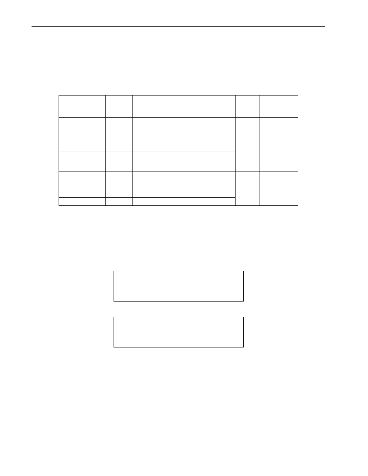
Omega Model CYC325 Temperature Controller User’s Manual
4.4 INPUT SETUP
The Model CYC325 supports a variety of temperature sensors sold by Omega and other manufacturers. An appropriate
sensor type must be selected for each of the two inputs. If the exact sensor model is not shown, use the sensor input
performance chart in Table 4-1 to choose an input type with similar range and excitation. For additional details on
sensors, refer to the Omega Temperature Handbook or visit our website at www.omega.com.
Input
Display Message
Range
Table 4-1. Sensor Input Types
Excitation Sensor Type
Curve
Format
Coefficient
Silicon Diode 2.5 V 10 µA Silicon Diode V/K Negative
GaAlAs Diode 7.5 V 10 µA
100Ω Plat/250 250 Ω
100Ω Plat/500 500 Ω
1000Ω Plat 5000 Ω
NTC RTD
7500 Ω
1 mA
1 mA
1 mA
10 µA
Thermo/25mV ±25 mV NA Thermocouple
Thermo/50mV
±50 mV NA Thermocouple
Gallium-Aluminum-Arsenide
Diode
V/K Negative
100 Ω Platinum RTD <675 K;
Rhodium-Iron RTD
Ω/K
100 Ω Platinum RTD >675 K
1000 Ω Platinum RTD Ω/K
Negative Temperature
Coefficient (NTC) RTD
log R/K Negative
mV/K Positive
Positive
Positive
4.4.1 Diode Sensor Input Setup – 10 µA Excitation Current
Diode sensors include the Silicon and Gallium-Aluminum-Arsenide (GaAlAs) detailed in Table 4-1. More detailed
specifications are provided in Section 1.2. Input ranges are fixed to 0
diodes. Both use a sensor excitation current of 10 µA.
To set up a diode sensor input, press the Input Setup key. The first screen appears as follows.
– 2.5 V for silicon diodes and 0 – 7.5 V for GaAlAs
Select With °®
Input Setup Input A
Use the s or t key to toggle between Input A and B. Press the Enter key.
Select for InputA °®
Type Silicon Diode
Use the s or t key to cycle through the sensor types shown in Table 4-1, with “Silicon Diode” and “GaAlAs Diode”
being the relevant choices. Press the Enter key. Proceed to Section 4.5.1 to select a temperature curve or press the
Escape key to return to the normal display.
4.4.2 Diode Sensor Input Setup – 1 mA Excitation Current
As an alternative to the standard diode input configuration listed in Section 4.4.1, the user may select 1 mA excitation
while the input configuration matches the diode input setup as detailed in Table 4-1. Input ranges are fixed to 0
and 0
– 7.5 V.
– 2.5 V
4-6 Operation
Page 51
Diode Sensor Input Setup – 1 mA Excitation Current (Continued)
Omega Model CYC325 Temperature Controller User’s Manual
To access the alternative setup, the diode current must be set to 1 mA. Press and hold the Input Setup key for
10 seconds to display the screen shown as follows:
Select for InputA °®
Diode Current 1mA
Use the s or t key to toggle between 10 µA and 1 mA to select the diode current for Input A. 1 mA must be selected
for the special sensor input to be available for Input A. Press the Enter key.
Select for InputB °®
Diode Current 1mA
Use the s or t key to toggle between 10 µA and 1 mA to select the diode current for Input B. 1 mA must be selected
for the special sensor input to be available for Input B. Press the Enter key.
To set up the diode input using 1 mA excitation, press the Input Setup key. The first screen appears as follows.
Select With °®
Input Setup Input A
Use the s or t key to toggle between Input A and B. Press the Enter key.
Select for InputA °®
Type 2.5V, 1mA
Use the s or t key to cycle through the sensor types shown in Table 4-1, with “2.5V, 1mA” and “7.5V, 1mA” being
the relevant choices. Press the Enter key. Proceed to Section 4.5.1 to select a temperature curve or press the Escape key
to return to the normal display.
4.4.3 Resistor Sensor Input Setup
Resistor sensors include the platinum, rhodium-iron, and various NTC RTD sensors (e.g., Cernox
™
, Rox™, Thermox™)
detailed in Table 4-1. More detailed specifications are provided in Table 1-2. Input range is fixed to type of sensor. The
excitation current applied by the Model CYC325 is determined by the user selection of Negative Temperature
Coefficient (NTC) = 10 µA or Positive Temperature Coefficient (PTC) = 1 mA.
To set up a resistor sensor input, press the Input Setup key. The first screen appears as follows.
Select With °®
Input Setup Input A
Use the s or t key to toggle between Input A and B. Press the Enter key.
Select for InputA °®
Type NTC RTD
Use the s or t key to cycle through the sensor types shown in Table 4-1, with “100Ω Plat/250,” “100Ω Plat/500,”
“1000Ω Plat,” and “NTC RTD” being the relevant choices. Press the Enter key.
Operation 4-7
Page 52

4.4.3.1 Thermal EMF Compensation
Omega Model CYC325 Temperature Controller User’s Manual
To keep power low and avoid sensor self-heating, the sensor excitation is kept low. There are two major problems that
occur when measuring the resulting small DC voltages. The first is external noise entering the measurement through the
sensor leads, which is discussed with sensor setup. The second problem is the presence of thermal EMF voltages,
sometimes called thermocouple voltages, in the lead wiring. Thermal EMF voltages appear whenever there is a
temperature gradient across a length of voltage lead. Thermal EMF voltages must exist because the sensor is almost
never the same temperature as the instrument. They can be minimized by careful wiring, making sure the voltage leads
are symmetrical in the type of metal used and how they are joined, and by keeping unnecessary heat sources away from
the leads. Even in a well-designed system, thermal EMF voltages can be an appreciable part of a low voltage sensor
measurement.
The Model CYC325 can help with a thermal correction algorithm. The instrument will automatically reverse the polarity
of the current source every other reading. The average of the positive and negative sensor readings will cancel the
thermal EMF voltage, which is present in the same polarity, regardless of current direction.
To turn reversal on or off, press the Input Setup key and press the Enter key until the following display appears.
Select for InputA °®
Reversal Off
Resistor sensors have the additional choice of turning current reversal On or Off, with the default being On. If turned On,
the Model CYC325 will automatically reverse the polarity. Press the Enter key.
Proceed to Section 4.5.2 to select a temperature curve or press the Escape key to return to the normal display.
4.4.4 Thermocouple Sensor Input Setup (Model CYC325-TX only)
The following thermocouple screens are only displayed when the Model CYC325 hardware is configured at the factory
with one or two thermocouple sensor inputs; being Model CYC325-T1 or T2.
The user has the choice of two different input voltage ranges: ±25 mV and ±50 mV. The ±25 mV range is recommended
for cryogenic applications or higher temperatures less than 500 K. Since thermocouple voltage can exceed 25 mV on
some thermocouple types, the ±50 mV range is recommended for temperatures above 500 K.
The voltage range for Inputs A and B is set independently. To set up a thermocouple sensor input, press the Input Setup
key. The first screen appears as follows.
Select With °®
Input Setup Input A
Use the s or t key to toggle between Input A and B. Press the Enter key.
Select for InputA °®
Type Thermo/25mV
Use the s or t key to cycle through the sensor types shown in Table 4-1, with “Thermo/25mV” and “Thermo/50mV”
being the relevant choices. Press the Enter key. Proceed to Section 4.4.4.1 to select a room-temperature compensation or
press the Escape key to return to the normal display.
4-8 Operation
Page 53

4.4.4.1 Room-Temperature Compensation
Omega Model CYC325 Temperature Controller User’s Manual
Room-temperature compensation is required to give accurate temperature measurements with thermocouple sensors.
It corrects for the temperature difference between the instrument thermal block and the curve normalization temperature
of 0 °C. An external ice bath is the most accurate form of compensation, but is often inconvenient. The Model CYC325
has built-in room-temperature compensation that is adequate for most applications. The built-in compensation can be
turned on or off by the user. It operates with any thermocouple type that has an appropriate temperature response curve
loaded. Room-temperature compensation is not meaningful for sensor unit measurements.
NOTE: Room temperature compensation should be calibrated as part of every installation.
To turn room temperature compensation on or off, press the Input Setup and press Enter until the following display
appears.
Select for InputA °®
Room Comp On
Use the s or t key to turn room-temperature compensation on or off, then press the Enter key. The default setting is
On. If the curve is set to “None,” the room-temperature compensation selection is automatically turned off.
4.4.4.2 Room-Temperature Calibration Procedure
Room-temperature calibration is used to calibrate the built-in compensation and is recommended when a thermocouple is
first installed or any time a thermocouple is changed.
Factory calibration of the instrument is accurate to within approximately ±1 K. Differences in thermocouple wire and
installation technique create errors greater than the instrument errors. Therefore, the best accuracy is achieved by
calibrating with the thermocouple actually being used because it eliminates all sources of error. If that is not possible, use
a thermocouple made from the same wire. For less demanding applications, a short across the input terminals will
suffice. If the Model CYC325 is configured as a dual-thermocouple unit, calibrate both inputs even if they use the same
type of thermocouple. An appropriate curve must be selected and room temperature compensation must be turned on
before calibration can be started.
There are three options for room temperature calibration:
• Cleared. The previous room-temperature calibration value is cleared and no adjustment will be made to the
temperature value provided by the internal temperature sensor when compensation is on.
• No. Use the room-temperature calibration value determined the last time the room-temperature calibration procedure
was performed.
• Yes. Perform the room-temperature calibration procedure that follows.
Calibration Procedure
1. Attach a thermocouple sensor or direct short across the input terminals of the thermocouple input. See Figure 3-4 for
polarity.
2. Place the instrument away from drafts. If calibrating using a short, place an accurate room-temperature thermometer
near the terminal block.
3. Allow the instrument to warm up for at least ½ hour without moving or handling the sensor.
4. If calibrating with a short skip to step 6, otherwise insert the thermocouple into the ice-bath, liquid nitrogen, helium
dewar, or other known fixed temperature. The temperature should be close to the measurement temperature that
requires best accuracy.
5. Read the displayed temperature. If the temperature display is not as expected, check to be sure that the thermocouple
is making good thermal contact. If possible, add a thermal mass to the end of the thermocouple.
6. Press the Input Setup key and press the Enter key until the “Room Cal” screen appears. Press the s or t key until
the “Yes” selection appears then press the Enter key.
Select for InputA °®
Room Cal Yes
Operation 4-9
Page 54

Room-Temperature Calibration Procedure (Continued)
7. The current temperature reading is displayed in kelvin.
Omega Model CYC325 Temperature Controller User’s Manual
Select for InputA
Temp 294.15½
Enter the true temperature that the thermocouple should read. If the input is shorted, then enter the actual room
temperature measured by the thermometer. Press the Enter key to save the value.
8. To verify calibration, check that the temperature reading for the calibrated input matches the room-temperature
calibration setting value.
4.5 CURVE SELECTION
The Model CYC325 supports a variety of temperature sensors sold by Omega and other manufacturers. After the
appropriate sensor type is selected for each of the two inputs (Section 4.4), an appropriate curve may be selected for
each input. The CYC325 can use curves from several sources. Standard curves are included with every instrument and
numbered 1
– 20. User curves, numbered 21 – 35, are loaded when a sensor does not match a standard curve. CalCurve
options are stored as user curves. SoftCal calibrations are stored as user curves or users can enter their own curves from
the front panel (Section 5.2) or computer interface (Chapter 6). The complete list of sensor curves built in to the
Model CYC325 is provided in Table 4-2.
During normal operation, only the curves related to the input type you have selected are displayed. If the curve you wish
to select does not appear in the selection sequence, make sure the curve format matches the recommended format for the
input type selected. Refer to Table 4-1.
NOTE: The sensor reading of the instrument can always be displayed in sensor units. If a temperature
Curve
Number
response curve is selected for an input, its readings may also be displayed in temperature.
Table 4-2. Sensor Curves
Display
Sensor
Type
Model
Number
Temperature
Range
For Data Points,
Refer To:
01 CY7 Silicon Diode CY7 1.4 – 475 K Table D-1
02 CY670 Silicon Diode CY670 1.4 – 500 K Table D-2
03 DT-500-D Silicon Diode DT-500-D 1.4 – 365 K Table D-3
04 DT-500-E1 Silicon Diode DT-500-E1 1.1 – 330 K Table D-3
05 Reserved – – – –
06 PT-100
07 PT-1000
100Ω Plat/250
100Ω Plat/500
1000Ω Plat
PT-100 30 – 800 K Table D-4
PT-1000 30 – 800 K Table D-4
08 RX-102A-AA NTC RTD Rox RX-102A 0.05 – 40 K Table D-5
09 RX-202A-AA NTC RTD Rox RX-202A 0.05 – 40 K Table D-6
10 Reserved – – – –
11 Reserved – – – –
12 Type K Thermo/25mV and 50mV Type K 3 – 1645 K Table D-7
13 Type E Thermo/25mV and 50mV Type E 3 – 1274 K Table D-8
14 Type T Thermo/25mV and 50mV Type T 3 – 670 K Table D-9
15 AuFe 0.03% Thermo/25mV and 50mV AuFe 0.03% 3.5 – 500 K Table D-10
16 AuFe 0.07% Thermo/25mV and 50mV AuFe 0.07% 3.15 – 610 K Table D-11
17 Reserved – – – –
18 Reserved – – – –
19 Reserved – – – –
20 Reserved – – – –
21 – 35 User Curves – – – –
4-10 Operation
Page 55
Omega Model CYC325 Temperature Controller User’s Manual
4.5.1 Diode Sensor Curve Selection
Once the input is set up for the silicon or gallium-aluminum-arsenide diode (Section 4.4.1), you may choose a
temperature curve. Standard curve numbers 1 through 4 are the relevant choices. You are also given the choice of
“None.” You may also choose from any appropriate User Curves stored in Curve Numbers 21 through 36. Data points
for standard diode curves are detailed in Tables D-1 through D-3 in Appendix D.
Press the Input Setup key. Press the Enter key until you see the curve selection screen shown below.
Select for InputA °®
Curve 01 DT-470
Use the s or t key to cycle through the sensor curves until the desired curve is displayed. Press the Enter key, then the
Escape key to return to the normal display.
4.5.2 Resistor Sensor Curve Selection
Once the input is set up for the platinum, rhodium-iron, or various NTC RTD sensors (Section 4.4.3), you may choose a
temperature curve. Standard curve numbers 6 and 7 are relevant to platinum; curves 8 and 9 are relevant to Rox sensors.
You are also given the choice of “None.” You may also choose from any appropriate User Curves stored in Curve
Numbers 21 through 35. Data points for resistor curves are detailed in Tables D-4 through D-6 in Appendix D.
Press the Input Setup key. Press the Enter key until you see the curve selection screen shown below.
Select for InputA °®
Curve 08 RX-102A-AA
Use the s or t key to cycle through the sensor curves until the desired curve is displayed. Press the Enter key, then the
Escape key to return to the normal display.
4.5.3 Thermocouple Sensor Curve Selection
The following thermocouple screens are only displayed when the Model CYC325 hardware is configured at the factory
with one or two thermocouple sensor inputs: Model CYC325-T1 or -T2.
Once the input is set up for the thermocouple input voltage (Section 4.4.4), you may choose a temperature curve. Press
the Input Setup key. Standard curve numbers 12 through 16 are relevant. You are also given the choice of “None.” You
may also choose from any appropriate User Curves stored in Curve Numbers 21 through 35. Data points for
thermocouple curves are detailed in Tables D-7 through D-11 in Appendix D. Press the Enter key until you see the
curve selection screen shown below.
Select for InputA °®
Curve 16 AuFe 0.07%
Use the s or t key to cycle through the sensor curves until the desired curve is displayed. Press the Enter key, then the
Escape key to return to the normal display.
4.5.4 Filter
The reading filter applies exponential smoothing to the sensor input readings. If the filter is turned on for a sensor input,
all reading values for that input are filtered. The filter is a running average, so it does not change the update rate of an
input. Filtered readings are used for displayed readings only, not for control functions.
The number of filter points determines how much smoothing is done. One filter point corresponds to one new reading on
that input. A larger number of points does more smoothing but also slows the instruments response to real changes in
temperature. The default number of filter points is 8, which settles in approximately 50 readings or 5 seconds.
Operation 4-11
Page 56
Filter (Continued)
Omega Model CYC325 Temperature Controller User’s Manual
The filter window is a limit for restarting the filter. If a single reading is different from the filter value by more than the
limit, the instrument will assume the change was intentional and restart the filter. Filter window is set in percent of fullscale range.
To configure a filter press the Input Setup key. The first screen appears as follows.
Select With °®
Input Setup Input A
Use the s or t key to toggle between Input A and B. Press the Enter key until the following display appears.
Select for InputA °®
Filter On
Use the s or t key to toggle between Filter On and Off. By selecting Off, the routine will end and return to the normal
display. By selecting On, the routine will continue with the following.
Select for InputA °®
Filter Points 08
Use the s or t key to increment or decrement the Filter Points from 02 through 64, with 08 being the default. Press the
Enter key. You will see the following display.
Select for InputA °®
Filter Window 01%
Use the s or t key to increment or decrement the Filter Window from 01% through 10%, with 01% being the default.
Press the Enter key. You will return to the normal display.
4.6 TEMPERATURE CONTROL
There are many steps involved in setting up a temperature control loop. Chapter 2 of this manual describes the principals
of closed loop (feedback) control. Chapter 3 describes necessary hardware installation. The following sections of this
chapter describe how to operate the control features and set control parameters. Each control parameter should be
considered before enabling a control loop or the instrument may not be able to perform the most simple control
functions. Good starting points include deciding which control loop to use, whether to operate in open or closed control
mode and which tuning mode is best for the application. Other parameters fall into place once these have been chosen.
4.6.1 Control Loops
The Model CYC325 is capable of running two simultaneous control loops. Their capabilities are compared in Table 4-3.
The primary difference between the two loops is their control output.
Loop 1: Loop 1, the primary control loop, is the traditional control loop for a cryogenic temperature controller. It
includes the largest set of hardware and software features, making it very flexible and easy to use. Loop 1 uses the
heater output as its control output. The heater output is a well-regulated 25 W DC output with two power ranges. This
provides quiet, stable control for a broad range of temperature control systems in a fully integrated package.
Loop 2: Loop 2, the auxiliary control loop, shares most of the operational features of loop 1 but uses the 2 W, 10 V
output as its control output. By itself, Loop 2 is capable of driving a sample heater or other low power load. It is also
suited to drive the programming input of a voltage programmable power supply. In combination, the controller and
supply can be used to control large loads at high temperatures.
4-12 Operation
Page 57
Control Loops (Continued)
Omega Model CYC325 Temperature Controller User’s Manual
The keypad and display operate on one loop at a time. To toggle display and keypad operation between Loop 1 and
Loop 2 press the Loop key. A brief display message indicates which control loop has been selected. You can determine
which loop is active by looking at the heater output display. Loop 1 has “Low” or “High” in the heater display. Loop 2
has “L2” in the heater display. Also, when you select any of the following parameters, the active loop number will be
displayed: Control Setup, Setpoint, P, I, D, Manual Heater, Zone Settings, AutoTune and Heater Range.
Table 4-3. Comparison of Control Loops 1 and 2
Feature Loop 1 Loop 2
Maximum Output Power 25 W 2 W
Output Type Current Source Voltage Source
Multiple Output Ranges Yes No
Closed Loop PID Control Yes Yes
AutoTune Yes Yes
Zone Tuning Yes Yes
Ramping Yes Yes
Open Loop Control Yes Yes
Front Panel Display Yes Yes
Setpoint Limit Yes Yes
4.6.2 Control Modes
The Model CYC325 offers two control modes, closed loop and open loop. To select a control mode refer to Section 4.7.
Closed Loop Control: Closed loop control, often called feedback control, is the control mode most often associated
with temperature controllers. In this mode the controller attempts to keep the load at exactly the user entered setpoint
temperature. To do this, it uses feedback from the control sensor to calculate and actively adjust the control output or
heater setting. The Model CYC325 uses a control algorithm called PID that refers to the three terms used to tune the
controller for each unique system. Manual heater power output can also be used during closed loop control. Closed
loop control is available for both control loops and offers several methods of tuning.
Open Loop Control: Open loop control is less complicated than closed loop control but is also less powerful. Open loop
control mode allows the user to directly set the manual heater power output for Loop 1 and Loop 2, using only the
Manual Heater Power (MHP) parameter. During open loop control, only the heater range and MHP output parameters
are active; the setpoint, control sensor and PID parameters are ignored. This type of control guarantees constant
power to the load but it does not actively control temperature. Any change in the characteristics of the load will cause
a change in temperature. Closed loop control is available for both loops, and no tuning is required.
4.6.3 Tuning Modes
The Model CYC325 offers three tuning modes or ways to set the necessary P, I and D parameters for closed loop
control. MHP output is active during closed loop control, and must be set to zero if not wanted. Heater range must also
be considered as part of tuning when using control Loop 1.
Manual PID Tuning: Manual tuning is the most basic tuning method. The user manually enters parameter values for
P, I, D, and heater range using their knowledge of the cooling system and some trial and error. Refer to Sections 2.7
and 4.8 for guidelines. Manual tuning can be used in any situation within the control capabilities of the instrument.
AutoTune: The Model CYC325 automates the tuning process with an AutoTune algorithm. This algorithm measures
system characteristics after a setpoint change and calculates P, I and D. The user must set heater range. AutoTune
will not work in every situation. Refer to Sections 2.8 and 4.9 for details.
Zone Tuning: Optimal control parameters values are often different at different temperatures within a system. Once
values have been chosen for each temperature range or zone, the zone feature can automatically select the correct set
each time the setpoint is changed. This mode does not help choose control parameter values; it helps use the values
more efficiently. Refer to Sections 2.7 and 4.10 for details.
Operation 4-13
Page 58

Omega Model CYC325 Temperature Controller User’s Manual
4.7 CONTROL SETUP
After the input setup has been completed (Section 4.4) and loop is selected (Section 4.6.1), the user can begin to set up
temperature control parameters.
Control input is the sensor input that is used for control feedback in closed loop control. Either input A or B can be
assigned to either Loop 1 or 2. It is not recommended to assign both loops to one input. Control input is ignored when
using open loop control mode. To change control input, press the Control Setup key and the following screen will
appear.
Select for Loop 1 °®
Control with Input A
Use the s or t key to toggle between Input A and B. Press the Enter key to accept the setting and continue with
additional selections. You can press the Escape key any time to exit the routine.
The control setpoint can be displayed and set in temperature or sensor units. Changing setpoint units does not change
operation of the controller, only the way the setpoint is displayed and entered. A valid curve must be assigned to the
control input to use temperature units. To change setpoint units press the Control Setup key and press Enter until the
following display appears.
Select for Loop 1 °®
SP Units Temp K
Use the s or t key to cycle through the following setpoint units: Temp K, Temp C, and Sensor, where K = kelvin,
C = degrees Celsius, and Sensor = volts (V), millivolts (mV), or ohms (Ω). Press the Enter key.
The Model CYC325 has two control modes, closed loop and open loop. Closed loop control, often called feedback
control, is described in Section 2.6 of this manual. During closed loop control operation, the Control Input, Setpoint,
Heater Range, PID, and Manual Heater Power (MHP) output parameters are active. Open loop control mode allows the
user to directly set the heater output for Loop 1 or Loop 2 with the MHP output parameter. During open loop control,
only the heater range and MHP output parameters are active. To change control mode, press the Control Setup key and
press Enter until the following display appears.
Select for Loop 1 °®
Control Mode Closed
Use the s or t key to toggle between open and closed loop control. Press the Enter key.
The Power Up setting refers to how the control output will respond after the instrument is powered down. Power Up
Enable means the controller will power up with the control output in the same state it was before power was turned off.
Power Up Disable means the controller will always power up with the heater off no matter how it was set when power
was turned off. To change the Power Up parameter press the Control Setup key and press Enter until the following
display appears.
4-14 Operation
Page 59

Control Setup (Continued)
Omega Model CYC325 Temperature Controller User’s Manual
Select for Loop 1 °®
Power Up Disable
Use the s or t key to toggle between Power Up Enable and Disable. Press the Enter key.
The Model CYC325 will display the heater output as either percent of full scale current or percent of full-scale power for
the heater range selected. This parameter affects the heater output display and the scale of the Manual Heater Power
(MHP) output parameter for Loop 1. The MHP output scale is always the same as the control output display. To change
control output units press the Control Setup key and press Enter until the following display appears.
Select for Loop 1 °®
Heater Out Power
Use the s or t key to toggle between Heater Out Power and Current. Press the Enter key.
4.8 MANUAL TUNING (Closed -Loop PID Control)
In manual PID mode, the controller will accept user-entered Proportional, Integral, and Derivative parameters to provide
three-term PID control. Manual heater power output can be set manually in open loop and closed loop control modes.
For details on PID tuning refer to Section 2.7.
To place the controller in Manual PID tuning mode, press the AutoTune key, and press the s or t key until you see the
following display.
Select for Loop 1 °®
Tune Mode Manual PID
Press the Enter key. The controller is now in Manual PID mode.
4.8.1 Manually Setting Proportional (P)
The proportional parameter (also called gain) is the P part of the PID control equation. It has a range of 0 to 1000 with a
resolution of 0.1. Enter a value greater than zero for P when using closed loop control.
To set Proportional, press the P key. You will see the following display.
Enter for Loop 1
Prop (P) 50.0
The Proportional (gain) limit is entered using the numeric keypad, which includes the numbers 0
point. Proportional has a range of 0 to 1000 with a default of 50. Press the Enter key to save changes and return to the
normal display.
– 9, +/–, and decimal
Operation 4-15
Page 60

Omega Model CYC325 Temperature Controller User’s Manual
4.8.2 Manually Setting Integral (I)
The integral parameter (also called reset) is the “I” part of the PID control equation. It has a range of 0 to 1000 with a
resolution of 0.1. Setting I to zero turns the reset function off. The I setting is related to seconds by:
setting
1000
I
seconds
.
I=
For example, a reset number setting of 20 corresponds to a time constant of 50 seconds. A system will normally take
several time constants to settle into the setpoint. The 50 second time constant, if correct for the system being controlled,
would result in a system that stabilizes at a new setpoint in between 5 and 10 minutes.
To set Integral, press the I key. You will see the following display.
Enter for Loop 1
Integ (I) 20.0
The Integral (reset) is entered using the numeric keypad, which includes the numbers 0
– 9, +/–, and decimal point.
Integral has a range of 0 to 1000 with a default of 20. Press the Enter key to save changes and return to the normal
display.
4.8.3 Manually Setting Derivative (D)
The derivative parameter (sometimes called rate) is the D part of the PID control equation. The rate time constant should
normally be somewhere between 1/4 and 1/8 the integral time in seconds, if used at all. As a convenience to the operator,
the Model CYC325 Derivative time constant is expressed in percent of ¼ the integral time. The range is between 0 and
200%. Start with settings of 0%, 50%, or 100%, and determine which setting gives you the type of control you desire.
Do not be surprised if the setting you prefer is 0. Note that by using a percent of integral time, derivative scales
automatically with changes in the integral value and does not have to be revisited frequently.
To set Derivative, press the D key. You will see the following display.
Enter for Loop 1
Deriv (D) 0.0
The Derivative (rate) is entered using the numeric keypad, which includes the numbers 0
Derivative has a range of 0 to 200 percent with a default of 0. Press the Enter key to save changes and return to the
normal display.
– 9, +/–, and decimal point.
4-16 Operation
Page 61

Omega Model CYC325 Temperature Controller User’s Manual
4.8.4 Setting Manual Heater Power (MHP) Output
Manual Heater Power (MHP) output is a manual setting of control output. It can function in two different ways
depending on control mode. In open loop control mode, the MHP output is the only output to the load. The user can
directly set control output from the front panel or over computer interface. In closed loop control mode, the MHP output
is added directly to the output of the PID control equation. In effect, the control equation operates about the MHP output
setting.
Manual heater power output setting is in percent of full scale. Percent of full scale is defined as percent of full-scale
current or power on the selected heater range. The manual heater power output setting range is 0% to 100% with a
resolution of 0.001%.
To enter a MHP Output setting, press the Manual Heater key. The following display appears.
Enter for Loop 1
Manual Out 0.00%
The MHP output setting is entered using the numeric keypad, which includes the numbers 0
– 9, +/–, and decimal point.
Press the Enter key, then the Escape key to return to the normal display.
4.9 AUTOTUNE (Closed-Loop PID Control)
The Model CYC325 automates the tuning process of typical cryogenic systems with the AutoTune feature. For
additional information about the algorithm, refer to Section 2.8.
Before initiating AutoTune, the cooling system must be set up properly with the control sensor and heater making it
capable of closed-loop control. AutoTune works only with one control loop at a time and does not set the manual heater
power output or heater range. The control sensor must have a valid temperature response curve assigned to it. An
appropriate heater range must also be determined as described in Section 2.7.1. Choosing good initial control parameters
by experimenting with Manual PID tuning can speed up the AutoTune process. If no initial parameters are known, start
with the default values of P = 50 and I = 20. It is better to set an initial P value that causes the system to be more active
than desired. Starting with a low P value can increase the time and number of attempts required to tune.
There are three AutoTune modes available. They result in slightly different system characteristics. Auto PI is
recommended for most applications.
Auto P – Sets only the P parameter value. I and D are set to 0 no matter what the initial values are. This mode is
recommended for systems that have very long lag times or nonlinearity that prevents stable PI control. Expect some
overshoot or undershoot of the setpoint and stable temperature control below the setpoint value.
Auto PI – Sets values for both P and I parameters. D is set to zero. This mode is recommended for stable control at a
constant temperature. It may take slightly longer to stabilize after setpoint change than Auto PID. Expect some
overshoot or undershoot of the setpoint and stable temperature control at the setpoint value.
Auto PID – Sets values for P, I and D parameters. D is always set to 100%. This mode is recommended when setpoint
changes are frequent but temperature is allowed to stabilize between changes. Stability at setpoint may be worse than
Auto PI in noisy systems. Expect slightly less overshoot or undershoot than the other modes and control at the
setpoint value.
Operation 4-17
Page 62

AutoTune (Continued)
Omega Model CYC325 Temperature Controller User’s Manual
Once AutoTune mode is selected, no activity takes place until the setpoint is changed at least 0.5 K. At that time, the
control channel annunciator blinks to indicate the instrument is gathering data. This process takes from 1 to 17 minutes
depending on the system reaction time. The control channel annunciator stops blinking when calculations are complete
and new parameter values have been stored. The annunciator will also stop blinking if the algorithm is unable to
complete. Possible reasons include: setpoint change too small, manual control parameter changed during tuning, heater
not turned on, or control sensor curve not selected.
If the controller is not tuned satisfactorily on the first attempt, make several small (2 degree) setpoint changes to see if
better parameter values are calculated.
To select an AutoTune mode, press the AutoTune key, and press the s, t, or AutoTune key to cycle the display to
AutoTune PID. You will see the following display.
Select for Loop 1 °®
Tune Mode Auto PID
Use the s or t key to cycle between Auto PID, Auto PI, and Auto P. Press the Enter key. The controller is now in
AutoTuning mode.
4.10 ZONE SETTINGS (Closed-Loop Control Mode)
The Model CYC325 allows the user to establish up to 10 custom contiguous temperature zones where the controller will
automatically use pre-programmed PID values and heater ranges. Zone control can be active for both control loops at the
same time. The user should configure the zones using 01 as the lowest to 10 as the highest zone. Zone boundaries are
always specified in kelvin (K). The bottom of the first zone is always 0 K. Therefore, only the upper limit is required for
all subsequent zones. Make a copy of Figure 4-4 to plan your zones.
Once all zone parameters have been programmed, the controller must be placed in zone tuning mode. To do this, press
the AutoTune key. Use the s or t key to select Zone. Then press Enter to accept the new tuning mode. Once zone is
turned on, the instrument will update the control settings each time the setpoint is changed to a new zone. If the settings
are changed manually, the controller will use the new setting while it is in the same zone and update to the zone table
settings when the setpoint is changed to a value outside that zone.
To enter parameter values into the zone table, press the Zone Settings key. You will see the following display.
Select for Loop 1 °®
Zone 01
Use the s or t key to cycle through the ten zones. Once the desired zone is displayed, press the Enter key. You will
see the next display.
Enter for Zone 01
SP Limit 0.0000½
The upper setpoint limit is entered using the numeric keypad, which includes the numbers 0
During numeric entry, you can press the Escape key one time to clear the entry, and a second time to exit to the normal
display.
NOTE: The default setting for all the zone setpoints is zero (0). The Model CYC325 will not search for
additional zones once it encounters a setpoint of zero.
4-18 Operation
– 9, +/–, and decimal point.
Page 63
Omega Model CYC325 Temperature Controller User’s Manual
Press the Enter key to accept the new upper limit. You will see the next display.
Enter for Zone 01
Prop (P) 50.0
The Proportional (P) value is entered using the numeric keypad, which includes the numbers 0 – 9, +/–, and decimal
point. Proportional has a range of 0 to 1000 with a default of 50. Press the Enter key to accept the new setting. You will
see the next display.
Enter for Zone 01
Integ (I) 20.0
The Integral (I) value is entered using the numeric keypad, which includes the numbers 0 – 9, +/–, and decimal point.
Integral has a range of 0 to 1000 with a default of 20. Press the Enter key to accept the new setting. You will see the
next display.
Enter for Zone 01
Deriv (D) 0.0
The Derivative (D) value is entered using the numeric keypad, which includes the numbers 0
Derivative has a range of 0 to 200 percent with a default of 0. Press the Enter key to accept the new setting. You will see
the next display.
– 9, +/–, and decimal point.
Enter for Zone 01
Manual Out 0.00%
The MHP output setting is entered using the numeric keypad, which includes the numbers 0
Manual heater has a range of 0 to 100 percent with a default of 0. Press the Enter key to accept the new heater setting.
Assuming the zone is controlling using Loop 1, you will see the next display.
– 9, +/–, and decimal point.
Select for Zone01 °®
Heater Range Off
Use the s or t key to select the Heater Range: High, Low, or Off. Press the Enter key to accept the new heater range
and return to the normal display. (If you are controlling using Loop 2, the last heater range setting is omitted.) This
completes the setting of Zone 01. Repeat the process for the subsequent zones.
Operation 4-19
Page 64
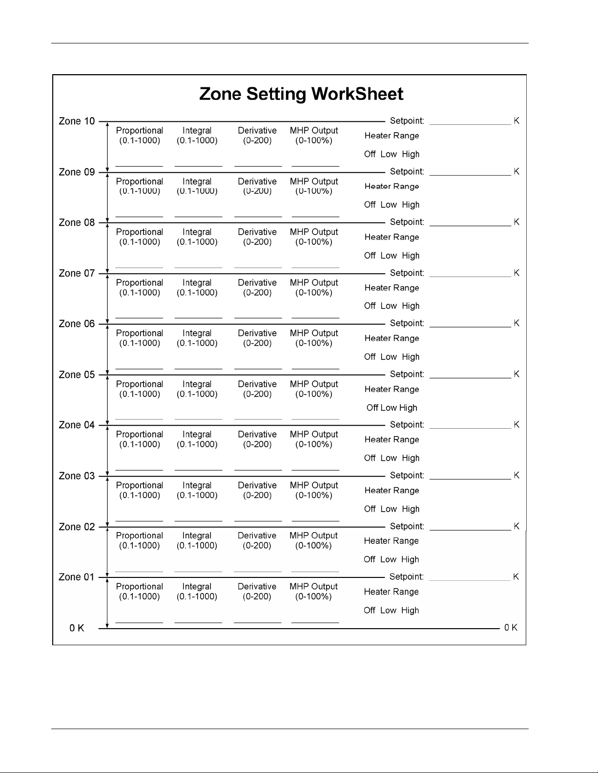
Omega Model CYC325 Temperature Controller User’s Manual
C-CYC325-4-4.bmp
Figure 4-4. Record of Zone Settings
4-20 Operation
Page 65

Omega Model CYC325 Temperature Controller User’s Manual
4.11 SETPOINT
The control setpoint is the desired load temperature expressed in temperature or sensor units. Use sensor units if no
temperature response curve is selected for the sensor input used as the control channel.
The control setpoint has its own units parameter. Set with the Control Setup key in Section 4.7. Control channel
readings can display in any units. Display units need not match setpoint units.
NOTE: If a curve is not assigned to the control input, control reverts to sensor units and the setpoint is set to
the most current reading.
When changing setpoint units while the control loop is active, the Model CYC325 converts the control setpoint to the
new control units for minimal disruption in control output.
Setpoint resolution depends on sensor type and setpoint units. With setpoint expressed in temperature, setpoint resolution
is 0.001 degree for setpoints below 100, and 0.01 for setpoints between 100 and 1000. In sensor units, the setpoint
resolution matches the display resolution for the sensor input type given in the specifications (Section 1.2).
The instrument allows a large setpoint range to accommodate a variety of sensors and units. With setpoint expressed in
sensor units, setpoint range is unlimited. The user must determine suitability of a setpoint value. In temperature units, a
safety feature limits the setpoint value to help prevent load damage. The setpoint limit in the temperature response curve
sets maximum safe temperature in kelvin for the sensor package. It can be verified by using the Curve Entry key. The
setpoint is limited to a value less than or equal to the limit. If the setpoint value changes from the number entered when
Enter is pressed, it is likely the setpoint exceeds the above limit or is inappropriate for the sensor type.
Once control setup parameters are configured (Section 4.7) and the active control loop is selected (Section 4.6.1), the
desired temperature setpoint is entered by pressing the Setpoint key.
Enter for Loop 1
Setpoint 77.350½
The setpoint is entered using the numeric keypad, which includes the numbers 0 – 9, +/–, and decimal point. Press the
Enter key to accept the new setpoint or press the Escape key to cancel.
If the display format is configured to show the setpoint (Section 4.3), you will see something resembling the following
for a normal display.
À 77.236½ Á 295.22½
 77.350½ 50% Low
Operation 4-21
Page 66

4.12 RAMP
The Model CYC325 generates a smooth setpoint ramp when the setpoint units are expressed in temperature. The user
can set a ramp rate in degrees per minute with a range of 0 to 100 and a resolution of 0.1. Once the ramp feature is turned
on, its action is initiated by a setpoint change. When a new setpoint is entered, the instrument changes the setpoint
temperature from the old value to the new value at the ramp rate. A positive ramp rate is always entered and it is used by
the instrument for ramps up and down in temperature.
The ramping feature is useful by itself but it is even more powerful when used with other features. Setpoint ramps are
often used with zone control mode. As temperature is ramped through different temperature zones, control parameters
are automatically selected for best control. Ramps can be initiated and status read back using a computer interface.
During computer-controlled experiments, the instrument generates the setpoint ramp while the computer is busy taking
necessary data. AutoTune does not function during a setpoint ramp. The ramp rate disguises the reaction of the cooling
system and no valid tuning data can be taken.
NOTE: When an incomplete ramp is shut off, the setpoint will remain on the most current setting, i.e., the
reading will not jump to the end of the ramp.
NOTE: If the input type or input curve is changed while a ramp is in progress, both ramping and the heater
are turned off.
NOTE: If Ramp is on and the setpoint is set to sensor units, the ramping function will remain on but when
another setpoint is entered, the setpoint goes directly to the new setpoint value.
To enable setpoint ramping, press the Control Setup key, then press the Enter key until you see the following display.
Omega Model CYC325 Temperature Controller User’s Manual
Select for Loop 1 °®
Setpoint Ramp On
Use the s or t key to select Setpoint Ramp On. Press the Enter key. You will see the following.
Enter for Loop 1
Ramp Rate 0.0 K/m
The ramp rate is entered using the numeric keypad, which includes the numbers 0 – 9 and decimal point. The user can set
a ramp rate in degrees per minute with a range of 0 to 100 and a resolution of 0.1. Ramp rate will be in the same units
specified for the setpoint. Press the Enter key. Any subsequent change in setpoint will ramp at the specified rate.
If you wish to pause a ramp, press the Setpoint key then immediately press the Enter key. This stops the ramp at the
current setpoint but leaves the ramping function activated. Then to continue the ramp, enter a new setpoint.
To turn the ramping feature off, press the Control Setup key, then press the Enter key until you see the following screen.
Select for Loop 1 °®
Setpoint Ramp Off
Use the s or t key to select Setpoint Ramp Off. Press the Enter key then the Escape key. The Ramp LED will turn
off.
4-22 Operation
Page 67

Omega Model CYC325 Temperature Controller User’s Manual
4.13 HEATER RANGE AND HEATER OFF
The heater output for Loop 1 is a well-regulated variable DC current source, while the heater output for Loop 2 is a
variable DC voltage source. Both heater outputs are optically isolated from the sensor input circuits to reduce
interference and ground loops. The heater output for the main control loop (Loop 1) can provide up to 25 W of
continuous power to a resistive heater load and includes a low range for systems with less cooling power, while the
Loop 2 heater output can provide up to 2 W of continuous power. Both Loop 1 and Loop 2 heater outputs are
short-circuit protected to prevent instrument damage if the heater load is accidentally shorted.
NOTE: During normal operation, if the input type or input curve is changed for the control input, the heater
will automatically shut off.
Specifications of the heater outputs are provided in Section 1.2 – Specifications. Heater theory of operation is provided
in Section 2.4 – Heater Selection and Installation. Various Heater installation considerations are provided in Section 3.6
– Heater Output Setup.
Once control setup parameters are configured (Section 4.7), and the active control loop is selected (Section 4.6.1), the
desired heater range is selected by pressing the Heater Range key.
Select for Loop 1 °®
Heater Range Off
Use the s or t key to cycle through Loop 1 Heater settings: Off, Low, and High. Once the desired heater setting is
displayed, press the Enter key. You will return to the normal display.
Use the s or t key to toggle between Loop 2 Heater settings: Off and On. Once the desired heater setting is displayed,
press the Enter key. You will return to the normal display.
To immediately turn the heater off, press the Heater Off key. If the Heater Range is not being displayed on the front
panel, the user should immediately press the Heater Range key to verify that the proper loop is displayed and the heater
shows Off.
4.14 HEATER RESISTANCE SETTING
The Model CYC325 Loop 1 and Loop 2 heater outputs are designed to accommodate two common heater resistance
values: 25 Ω and 50 Ω. In order to achieve full output power, and stable temperature control over the full output range
(0 – 100%) the heater resistance setting must be set properly for both control loops. For Loop 1, the heater resistance
setting controls the heater output compliance voltage (50 Ω setting = 36 V nominal, 25 Ω setting = 25 V nominal).
Loop 1 was designed to provide 0 – 1 A of output current for heaters up to 20% lower than the nominal heater resistance
when the proper heater resistance setting is used. For Loop 2, the heater resistance setting controls the heater output fullscale voltage (50 Ω setting = 10 V, 25 Ω setting = 5 V). If the heater resistance setting is not set properly limiting could
occur, which could result in temperature control instability. An exception occurs when using a heater greater than the
heater resistance setting on Loop 2. In this situation the maximum heater power is lowered as the heater resistance
increases, but control over the full output range will not be limited.
To set the heater resistance for the currently displayed loop, press the Control Setup key, then press the Enter key until
you see the following display.
Select for Loop 1 °®
Heater Load: 25¦
Use the s or t key to select 25 Ω or 50 Ω. Press the Enter key to save changes and return to the normal display.
Operation 4-23
Page 68

4.15 LOCKING AND UNLOCKING THE KEYPAD
The keypad lock feature prevents accidental changes to parameter values. When the keypad is locked, some parameter
values may be viewed, but most cannot be changed from the front panel. Heater Off is the only keypad function that
remains active when the keypad is locked.
A 3-digit keypad lock code locks and unlocks the keypad. The factory default code is 123. The code can be changed only
through the computer interface. If instrument parameters are reset to default values, the lock code resets also. The
instrument cannot reset from the front panel with the keypad locked.
To lock the keypad, press and hold the Enter key for 10 seconds to display the screen shown as follows.
Omega Model CYC325 Temperature Controller User’s Manual
Enter Code To
Lock Keypad
Use the numeric keypad to enter the 3-digit lock code. The keypad locks and the normal display appears. Changes
attempted to any parameters result in a brief display of the *LOCKED* message.
To unlock the keypad, press and hold the Enter key for 10 seconds to display the screen shown as follows.
Enter Code To
Unlock Keypad
Use the numeric keypad to enter the 3-digit lock code. The keypad unlocks and the normal display again appears. All
Model CYC325 parameters are now accessible.
4.16 REMOTE/LOCAL
“Local” refers to operating the Model CYC325 from the front panel. “Remote” refers to operating the controller via the
IEEE-488 Interface. The keypad is disabled during remote operation. The mode of operation can be changed by pressing
the Remote/Local key. When in remote mode an “R” will be displayed in the rightmost character on the top line of the
LCD display. When in local mode, the character will be blank.
4.17 INTERFACE
The Interface key serves two functions: set the serial interface baud rate, and set the IEEE-488 interface address and
terminators.
To set the serial interface baud rate, press the Interface key.
Select With °®
Baud 9600
Use the s or t key to cycle through the choices of 9600, 19200, 38400, 57600 baud. The default baud rate is 9600.
Press the Enter key to accept the changes or the Escape key to keep the existing setting and return to the normal display.
4-24 Operation
Page 69

Interface (Continued)
To set the IEEE-488 interface address and terminators, press the Interface key, then press the Enter key until you see
the following screen.
Omega Model CYC325 Temperature Controller User’s Manual
Select With °®
IEEE Address 12
Use the s or t key to increment or decrement the IEEE address to the desired number. The default address is 12.
Press the Enter key to accept the changes or the Escape key to keep the existing setting and return to the normal display.
Press the Enter key again to see the following screen.
Select With °®
IEEE Term Cr Lf
Use the s or t key to cycle through the following terminator choices: Cr Lf, Lf Cr, Lf, or EOI, where Cr = Carriage
Return, Lf = Line Feed, and EOI = End Or Identify. The default terminator is Cr Lf. Press the Enter key to accept the
changes and continue to the next screen, or the Escape key to keep the existing setting and return to the normal display.
4.18 DEFAULT VALUES
It is sometimes necessary to reset instrument parameter values or clear out the contents of curve memory. Both are all
stored in nonvolatile memory called NOVRAM but they can be cleared individually. Instrument calibration is not
affected except for Room Temperature Calibration, which should be redone after parameters are set to default values or
any time the thermocouple curve is changed.
To reset the Model CYC325 parameters to factory default values, press and hold the Escape key until the screen shown
below appears.
Main Version: 1.0
Default Values Yes
Use the s or t key to select Yes or No to reset the NOVRAM. Select Yes to reset all Model CYC325 parameters to the
defaults listed in Table 4-5. Press the Enter key. The second screen appears as follows.
Input Version 1.0
Clear Curves No
Use the s or t key to select Yes or No to clear the user curves (in locations 21
Standard curves (in locations 1 – 20) are unaffected. Press the Enter key. The instrument performs the operation then
returns to the normal display.
Operation 4-25
– 35) stored in the Model CYC325.
Page 70

Omega Model CYC325 Temperature Controller User’s Manual
Table 4-4. Default Values
Control Setup
Control Input ................... Input A
SP Units........................... Temp K
Control Mode .................. Closed
Power Up......................... Disable
Setpoint Ramp ................. Off
Heater Output Display..... Current
Display Format
Display Location 1 .......... Input A / Temp K
Display Location 2 .......... Input B / Temp K
Display Location 3 .......... Setpoint
Display Location 4 .......... Heater Output
Heater
Heater Range ................... Off
Input Setup – Diode/Resistor Configuration
Input Type ....................... Silicon Diode
Curve ............................... DT-470
Input Setup – Thermocouple Configuration
Input Type ....................... Thermocouple/25mV
Curve ............................... Type K
Room Comp .................... On
Room Cal......................... Cleared
Interface
Baud ................................ 9600
IEEE Address .................. 12
IEEE Terminators............ CR/LF
Keypad Locking
Mode........................................ Unlocked
Lock Code ............................... 123
Loop
Selected Loop .......................... Loop 1
PID/Manual Heater Power (MHP) Output
Proportional (P) ....................... 50.0
Integral (I)................................ 20.0
Derivative (D).......................... 0.0
MHP Output ............................ 0.000%
Remote/Local
Remote/Local...........................Local
Setpoint
Setpoint Value ......................... 0.000K
Tuning
Tuning Mode ........................... Manual PID
Zone Settings – All Zones
Setpoint Limit.......................... 0.000 K
Proportional (P) ....................... 50.0
Integral (I)................................ 20.0
Derivative (D).......................... 0.00
Manual Output......................... 0.000%
4-26 Operation
Page 71

Omega Model CYC325 Temperature Controller User’s Manual
CHAPTER 5
ADVANCED OPERATION
5.0 GENERAL
This chapter provides information on the advanced operation of the Model CYC325 temperature controller.
5.1 CURVE NUMBERS AND STORAGE
The Model CYC325 has 20 standard curve locations; numbered 1 through 20. At present, not all locations are occupied
by curves; the others are reserved for future updates. If a standard curve location is in use, the curve can be viewed using
the edit operation. Standard curves cannot be changed by the user, and reserved locations are not available for user
curves.
The Model CYC325 has 15 user curve locations numbered 21 through 35. Each location can hold from 2 to 200 data
pairs (breakpoints), including a value in sensor units and a corresponding value in kelvin. Using fewer than 200
breakpoints will not increase the number of available curve locations. SoftCal-generated curves are stored in user curve
locations.
5.1.1 Curve Header Parameters
Each curve has parameters that are used for identification and to allow the instrument to use the curve effectively.
The parameters must be set correctly before a curve can be used for temperature conversion or temperature control.
Curve Number: 1
Name: Defaults to the name User Curve for front panel entry. When entering a user curve over the computer interface, a
curve name of up to 15 characters can be entered.
Serial Number: Up to a 10-character sensor serial number. Both numbers and letters can be entered over computer
interface; only numbers can be entered from the front panel.
Format: The format parameter tells the instrument what breakpoint data format to expect. Different sensor types require
different formats. Formats for Omega sensors are:
V/K: Volts vs. kelvin for diode sensors.
Ω/K: Resistance vs. kelvin for platinum RTD sensors.
Log Ω/K: Log resistance vs. kelvin for NTC resistive sensors.
mV/K: Millivolts vs. kelvin for thermocouple sensors.
Limit: Enter a temperature limit in kelvin for the curve. Default is 375 K. Enter a setting of 9999 K if no limit is needed.
Temperature Coefficient: The unit derives the temperature coefficient from the first two breakpoints. The user does not
enter this setting. If it is not correct, check for proper entry of those points. A positive coefficient (P) indicates that
the sensor signal increases with increasing temperature. A negative coefficient (N) indicates that the sensor signal
decreases with increasing temperature.
– 35.
5.1.2 Curve Breakpoints
Temperature response data of a calibrated sensor must be reduced to a table of breakpoints before entering it into the
instrument. Each breakpoint consists of one value in sensor units and one temperature value in kelvin. Linear
interpolation is used by the instrument to calculate temperature between breakpoints. From 2 to 200 breakpoints can be
entered as a curve. The instrument will show an error message on the display if the sensor input is outside the range of
the breakpoints. No special endpoints are required. Sensor units are defined by the format setting in Table 5-2.
Breakpoint setting resolution is six digits in temperature. Most temperature values are entered with 0.001 resolution.
Temperature values of 1000 K and greater can be entered to 0.01 resolution. Temperature values below 10 K can be
entered with 0.0001 resolution. Temperature range for curve entry is 1500 K.
Advanced Operation 5-1
Page 72
Name:
Serial Num:
Curve
Format:
SP Limit
Omega Model CYC325 Temperature Controller User’s Manual
Table 5-1. Curve Header Parameters
The curve name cannot be changed from the front panel. Curve names can only be entered over the
computer interface (up to 15 characters). The default curve name is User xx, where xx is the curve
number.
Identify specific sensors with serial numbers of up to 10 characters. The serial number field accepts
both numbers and letters, but the instrument front panel enters only numbers. To enter both numbers
and letters, enter curves over computer interface. The default is blank.
The instrument must know the data format of the curve breakpoints. Different sensor types use
different data formats. The sensor inputs require one of the formats below. The range and resolution
specified are not always available at the same time. Practical range and resolution depend on the
sensor type.
Sensor Units Sensor Units
Format Description Full Scale Range Maximum Resolution
V/K Volts vs. kelvin 10 (V) 0.00001 (V)
Ω/K Resistance vs. kelvin 10 K (Ω) 0.001 (Ω)
log Ω/K Log resistance vs. kelvin 4 (log Ω) 0.00001 (log Ω)
mV/K Millivolts vs. kelvin ±100 (mV) 0.0001 (mV)
A setpoint temperature limit can be included with every curve. When controlling in temperature, the
setpoint cannot exceed the limit entered with the curve for the control sensor. The default is 375 K.
Set to 9999 K if no limit is required.
The instrument derives the temperature coefficient from the first two breakpoints. If it is set
Coeff:
improperly, check the first two breakpoints. A positive coefficient indicates the sensor signal
increases with increasing temperature. A negative coefficient indicates the sensor signal decreases
with increasing temperature.
Table 5-2. Recommended Curve Parameters
Type Units Format
Limit
(K)
Coefficient
Silicon Diode V V/K 475 Negative 0.00001 (V)
GaAlAs Diode V V/K 325 Negative 0.00001 (V)
Platinum 100
Platinum 1000
Rhodium-Iron
Carbon-Glass
Cernox™
Germanium
Rox™
Ω
Ω
Ω
Ω
Ω
Ω
Ω
Ω/K
Ω/K
Ω/K
logΩ/K
logΩ/K
logΩ/K
logΩ/K
800 Positive 0.001 (Ω)
800 Positive 0.01 (Ω)
325 Positive 0.001 (Ω)
325 Negative
325 Negative
325 Negative
40 Negative
Type K mV mV/K 1500 Positive 0.0001 (mV)
Type E mV mV/K 930 Positive 0.0001 (mV)
Type T mV mV/K 673 Positive 0.0001 (mV)
Au-Fe 0.03% mV mV/K 500 Positive 0.0001 (mV)
Au-Fe 0.07% mV mV/K 610 Positive 0.0001 (mV)
Recommended Sensor
Resolution
0.00001 (logΩ)
0.00001 (logΩ)
0.00001 (logΩ)
0.00001 (logΩ)
5-2 Advanced Operation
Page 73
Curve Breakpoints (Continued)
Omega Model CYC325 Temperature Controller User’s Manual
Setting resolution is also six digits in sensor units. The curve format parameter defines the range and resolution in sensor
units as shown in Table 5-2. The sensor type determines the practical setting resolution. Table 5-2 lists recommended
sensor units resolutions. For most sensors, additional resolution is ignored.
The breakpoints should be entered with the sensor units value increasing as point number increases. There should not be
any breakpoint locations left blank in the middle of a curve. The search routine in the Model CYC325 interprets a blank
breakpoint as the end of the curve.
5.2 FRONT PANEL CURVE ENTRY OPERATIONS
There are three operations associated with front panel curve entry: Edit curve, Copy curve, Erase curve; as detailed
below.
Edit Curve
Erase Curve
Copy Curve
SoftCal
Edit allows the user to see any curve and enter or edit a curve at any
user curve location. Standard curves cannot be changed.
Erase allows the user to delete a curve from any user curve location.
Standard curves cannot be erased.
Copy allows the user to copy a curve from any location to any user
curve location. Curves cannot be copied into standard curve locations.
Allows creation of a new temperature curve from a standard curve and
known data points entered by the user.
Refer to Section 5.2.1
Refer to Section 5.2.2
Refer to Section 5.2.3
Refer to Section 5.3
To begin a curve operation, press the Curve Entry key and the above selections appear. Press the Next Setting key until
the desired operation is highlighted and press the Enter key. A curve screen appears with the curve number highlighted.
Change to the desired curve number with the up or down arrow key, then press the Enter key to begin the desired curve
operation.
5.2.1 Edit Curve
The Edit Curve operation is used to enter a new curve or edit an existing user curve. Only user curves (21 to 35) can be
changed. Standard curves can only be viewed with the edit operation. Entering the identification parameters associated
with the curve is as important as entering the breakpoints. Curve header parameters are listed in Table 5-1. Typical
parameters for common sensors are listed in Table 5-2. Read this section completely and gather all necessary data before
beginning the process.
NOTE: If the curve you wish to enter has similar parameters to an existing curve, first copy the similar curve
(as described in Section 5.2.3) to a new location, then edit the curve to the desired parameters.
To enter a new user curve or edit an existing user curve, press the Curve Entry key. Press the s or t key until you see
the following display.
Select With °®
Edit Curve
Press the Enter key. Press the Escape key any time during this routine to return to the normal display.
Select for Edit °®
Curve 21 User
Use the s or t key to cycle through the various curves. Curve numbers 21 through 35 are used to copy or create new
curves. You can also view (but not modify) the standard curve numbers 01 through 20 from here. For this example, we
will enter a new curve in location 21. Press the Enter key.
Advanced Operation 5-3
Page 74
Edit Curve (Continued)
Omega Model CYC325 Temperature Controller User’s Manual
Enter for Curve 21
Serial # 0123456789
Use the numerical keypad to enter the applicable sensor serial number; to a maximum of 10 digits. For this example, we
will enter 0123456789. Press the Enter key.
Select for Curv21 °®
Curve Format V/K
Use the s or t key to cycle through the curve formats: V/K, Ω/K, log Ω/K, mV/K, where V/K = volts per kelvin,
Ω/K = ohms per kelvin, log Ω/K = logarithm of the resistance per kelvin, and mV/K = millivolts per kelvin. For this
example, we will select V/K. Press the Enter key.
Enter for Curve 21
SP Limit 475.00½
Use the numerical keypad to enter a setpoint limit (in kelvin) appropriate for the sensor being used. For this example, we
will enter 475.00K. Press the Enter key.
View for Curve 21
Temp Coeff Positive
The temperature coefficient (positive or negative) of the curve is displayed. The coefficient is calculated from the first
two points of the curve and cannot be changed. Press the Enter key.
Now that the curve identification parameters are entered, it is time to enter curve breakpoints.
User Curve 21
¾ 0.00000v 00.0000½
The cursor initially blinks on the curve breakpoint number. When the cursor is in this position, use the s or t key to
scroll through the breakpoints in the curve. Press the Enter key to modify the current breakpoint. Use the numerical
keypad to enter the applicable sensor value. For this example, we will enter 0.09062V, then press the Enter key. The
cursor will jump to the temperature reading. Again use numerical keypad to enter the applicable temperature in kelvin.
For this example, we will enter 475.0K. Press the Enter key.
¾ 0.09062v 475.000½
¿ 0.00000v 00.0000½
Use the numerical keypad to enter the remaining voltage and temperature points. After entering the final point in the
curve, press the Enter key, then the Escape key. You will return to the normal display.
To add a new breakpoint to an existing curve, go to the end of the curve data and enter the new sensor reading and
temperature. Press the Enter key, then the Escape key. The new point is automatically put into its proper place in
breakpoint sequence.
5-4 Advanced Operation
Page 75
Edit Curve (Continued)
NOTE: Typing over an existing reading or temperature will replace that value when you press the Enter key.
Omega Model CYC325 Temperature Controller User’s Manual
To delete a breakpoint, go to point and enter zeros for both the sensor reading and temperature. Press the Enter key, then
the Escape key.
When curve entry is complete, the user must assign the new curve to an input. The Model CYC325 does not
automatically assign the new curve to either input.
5.2.1.1 Thermocouple Curve Considerations
The following are things to consider when generating thermocouple curves.
• Users may enter temperature response curves for all types of thermocouples. Enter curve data in mV/K format with
thermocouple voltage in millivolts and temperature in kelvin.
• The curve must be normalized to 0 mV at 273.15 K (0 °C). Thermocouple voltages in millivolts are positive when
temperature is above that point and negative when temperature is below that point.
• To convert curves published in Celsius to kelvin, add 273.15 to the temperature in Celsius.
• The temperature range for some thermocouple types may extend below 1 K or above 1000 K.
• The input voltage of the CYC325 is limited to ±50 mV, so any part of the curve that extends beyond ±50 mV is not
usable by the instrument.
• A message of S-OVER or S-UNDER on the display indicates that the measured thermocouple input is over or under
the ±50 mV range.
5.2.2 Erase Curve
User curves that are no longer needed may be erased. Erase Curve sets all identification parameters to default and blanks
all breakpoint values.
To erase an existing user curve, press the Curve Entry key. Press the s or t key until you see the following display.
Select With °®
Erase Curve
Press the Enter key. You can press the Escape key any time during this routine to return to the normal display.
Select for Erase °®
Curve 21 User
Use the s or t key to cycle through the various user curve numbers 21 through 35. You cannot erase the standard curve
numbers 01 through 20. Once the user curve number is selected, press the Enter key. You will see the following
message.
Press Esc. to cancel
or Enter to erase 21
Press the Escape key to cancel or the Enter key to erase the selected user curve. You now return to the normal display.
Advanced Operation 5-5
Page 76
Omega Model CYC325 Temperature Controller User’s Manual
5.2.3 Copy Curve
Temperature curves can be copied from one location inside the Model CYC325 to another. This is a good way to make
small changes to an existing curve. Curve copy may also be necessary if the user needs the same curve with two different
temperature limits or needs to extend the range of a standard curve. The curve that is copied from is always preserved.
NOTE: The copy routine allows you to overwrite an existing user curve. Please ensure the curve number you
To copy a curve, press the Curve Entry key. Press the s or t key until you see the following display.
are writing to is correct before proceeding with curve copy.
Select With °®
Copy Curve
Press the Enter key. You can press the Escape key any time during this routine to return to the normal display.
Select Copy from °®
Curve 01 DT-470
Use the s or t key to select the curve number (01 through 35) to copy from. Once the curve number is selected, press
the Enter key. You will see the following message.
Select Copy to °®
Curve 21 User
Use the s or t key to select the curve number (21 through 35) to copy to. Press the Enter key to copy the curve. You
now return to the normal display.
5.3 SOFTCAL™
The Model CYC325 allows the user to perform inexpensive sensor calibrations with a set of algorithms called SoftCal.
The two SoftCal algorithms in the Model CYC325 work with CY7 Series silicon diode sensors and platinum sensors.
They create a new temperature response curve from the standard curve and known data points entered by the user. The
new curve loads into one of the user curve locations (21 through 35) in the instrument. The following sections describe
the data points needed from the user and the expected accuracy of the resulting curves.
Both CY7 Series and platinum SoftCal algorithms require a standard curve that is already present in the Model CYC325.
When the user enters the type of sensor being calibrated, the correct standard curve must be selected. When calibration is
complete, the user must assign the new curve to an input. The Model CYC325 does not automatically assign the newly
generated curve to either input.
Calibration data points must be entered into the Model CYC325. These calibration points are normally measured at
easily obtained temperatures like the boiling point of cryogens. Each algorithm operates with one, two, or three
calibration points. The range of improved accuracy increases with more points.
To get SoftCal calibration data points, the user can record the response of an unknown sensor at well-controlled
temperatures.
When the user can provide stable calibration temperatures with the sensor installed, SoftCal calibration eliminates errors
in the sensor measurement as well as the sensor. Thermal gradients, instrument accuracy, and other measurement errors
can be significant to some users. Calibration can be no better than user-supplied data.
5-6 Advanced Operation
Page 77
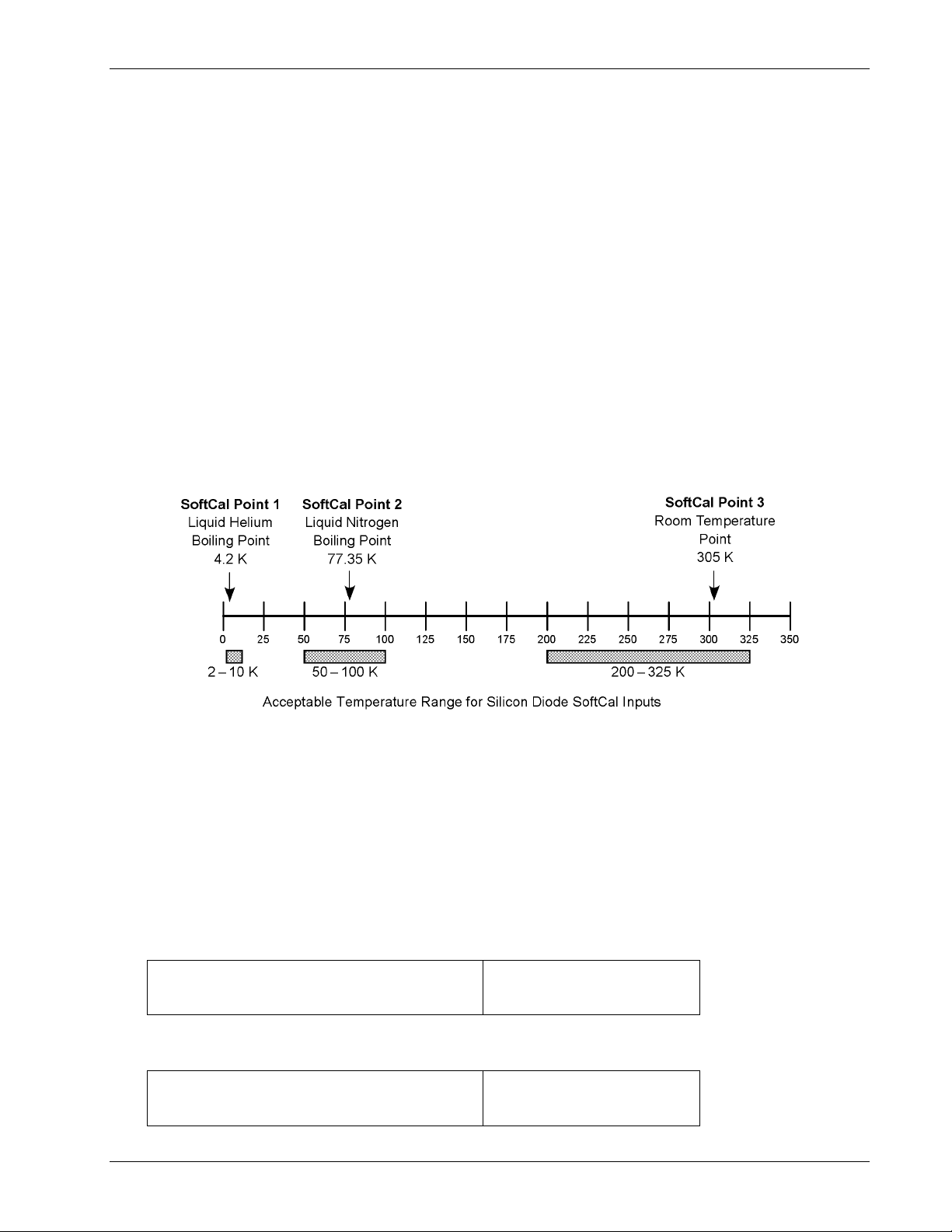
Omega Model CYC325 Temperature Controller User’s Manual
5.3.1 SoftCal™ with Silicon Diode Sensors
Omega silicon diode sensors incorporate remarkably uniform sensing elements that exhibit precise, monotonic, and
repeatable temperature response. For example, the Omega CY7 Series of silicon diode sensors has a repeatable
temperature response from 2 K to 475 K. These sensors closely follow the standard Curve 10 response and routinely
interchange with one another. SoftCal is an inexpensive way to improve the accuracy of an already predictable sensor.
NOTE: Standard Curve 10 is the name of the temperature response curve, not its location inside the
Model CYC325. Standard Curve 10 is stored in curve location number 1 in the Model CYC325.
A unique characteristic of CY7 Series diodes is that their temperature responses pass through 28 K at almost exactly the
same voltage. This improves SoftCal algorithm operation by providing an extra calibration data point. It also explains
why SoftCal calibration specifications are divided into two temperature ranges, above and below 28 K. See Figure 5-1.
Point 1: Calibration data point at or near the boiling point of helium, 4.2 K. Temperatures outside 2 K to 10 K are not
allowed. This data point improves between the calibration data point and 28 K. Points 2 and 3 improve temperatures
above 28 K.
Point 2: Calibration data point at or near the boiling point of nitrogen (77.35 K). Temperatures outside 50 K to 100 K are
not allowed. This data point improves accuracy between 28 K and 100 K. Points 2 and 3 together improve accuracy
to room temperature and above.
Point 3: Calibration data point near room temperature (305 K). Temperatures outside the range of 200 K to 350 K are
not allowed.
C-CYC325-5-1.bmp
Figure 5-1. SoftCal Temperature Ranges for Silicon Diode Sensors
5.3.2 SoftCal™ Accuracy with Silicon Diode Sensors
A SoftCal calibration is only as good as the accuracy of the calibration points. The accuracies listed for SoftCal assume
±0.01 K for 4.2 K (liquid helium), ±0.05 K for 77.35 K (liquid nitrogen), and 305 K (room temperature) points. Users
performing the SoftCal with Omega instruments should note that the boiling point of liquid cryogen, though accurate, is
affected by atmospheric pressure. Use calibrated standard sensors if possible.
One-point SoftCal calibrations for applications under 30 K are performed at liquid helium (4.2 K) temperature. Accuracy
for the CY7-SD-4 diode is ±0.5 K from 2 K to <30 K with no accuracy change above 30 K.
Two-point SoftCal calibrations for applications above 30 K are performed at liquid nitrogen (77.35 K) and room
temperature (305 K). Accuracy for the CY7-SD4 diode sensor is as follows:
±1.0 K 2 K to <30 K (no change below 30 K)
±0.25 K 30 K to <60 K
±0.15 K 60 K to <345 K
±0.25 K 345 K to <375 K
±1.0 K 375 to 475 K
Three-point SoftCal calibrations are performed at liquid helium (4.2 K), liquid nitrogen (77.35 K), and room temperature
(305 K). Accuracy for the CY7-SD4 diode sensor is as follows:
±0.5 K 2 K to <30 K
±0.25 K 30 K to <60 K
±0.15 K 60 K to <345 K
±0.25 K 345 K to <375 K
±1.0 K 375 to 475 K
Advanced Operation 5-7
Page 78
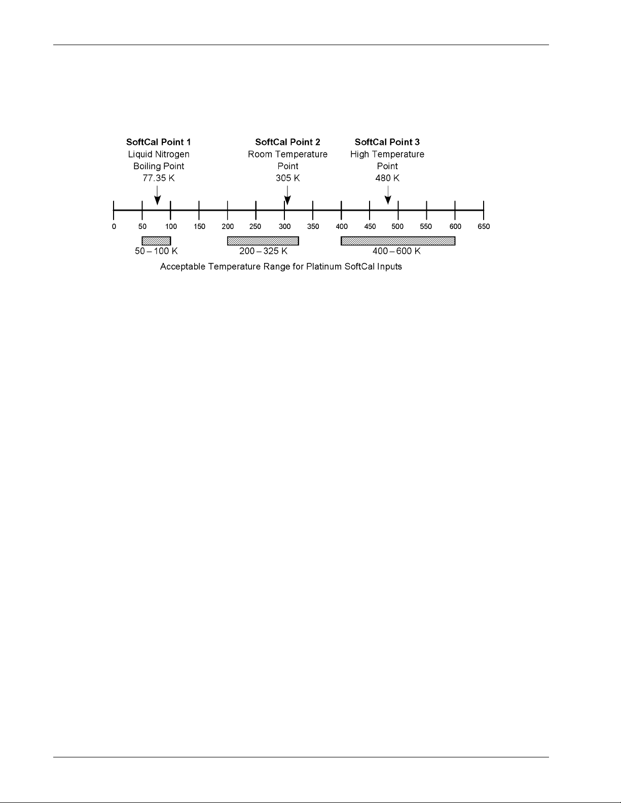
Omega Model CYC325 Temperature Controller User’s Manual
5.3.3 SoftCal™ with Platinum Sensors
The platinum sensor is a well-accepted temperature standard because of its consistent and repeatable temperature
response above 30 K. SoftCal gives platinum sensors better accuracy than their nominal matching to the DIN 43760
curve.
C-CYC325-5-2.bmp
Figure 5-2. SoftCal Temperature Ranges for Platinum Sensors
One, two, or three calibration data points can be used. If using one point, the algorithm shifts the entire curve up or down
to meet the single point. If using two points, the algorithm has enough information to tilt the curve, achieving good
accuracy between the data points. The third point extends the improved accuracy to span all three points.
Point 1: Calibration data point at or near the boiling point of nitrogen (77.35 K). Temperatures outside 50 K to 100 K are
not allowed.
Point 2: Calibration data point near room temperature (305 K). Temperatures outside 200 K to 350 K are not allowed.
Point 3: Calibration data point at a higher temperature (480 K). Temperatures outside 400 K to 600 K are not allowed.
5.3.4 SoftCal™ Accuracy with Platinum Sensors
A SoftCal calibration is only as good as the accuracy of the calibration points. The accuracies listed for SoftCal assume
±0.05 K for 77.35 K (liquid nitrogen) and 305 K (room temperature) points. Users performing the SoftCal with Omega
instruments should note that the boiling point of liquid cryogen, though accurate, is affected by atmospheric pressure.
Use calibrated standard sensors if possible.
One-point SoftCal calibrations with platinum sensors have no specified accuracy.
Two-point SoftCal calibrations for applications above 70 K are performed at liquid nitrogen (77.35 K) and room
temperature (305 K). Accuracy for the PT-102, PT-103, or PT-111 platinum sensor is as follows:
±250 mK from 70 K to 325 K
≈±500 mK from 325 K to ≈±1400 mK at 480 K
(DIN Class A or Class B tolerance)
Three-point SoftCal calibrations are performed at liquid nitrogen (77.35 K), room temperature (305 K), and high
temperature (480 K). Accuracy for the PT-102, PT-103, or PT-111 platinum sensor is
±250 mK from 70 K to 325 K, and
±250 mK from 325 K to 480 K.
5-8 Advanced Operation
Page 79
Omega Model CYC325 Temperature Controller User’s Manual
5.3.5 SoftCal™ Calibration Curve Creation
Once the calibration data points have been obtained, you may create a SoftCal calibration. This example illustrates
SoftCal of a CY7 diode. Press the Curve Entry key. Press the s or t key until you see the following display.
Select With °®
SoftCal
Press the Enter key. You can press the Escape key any time during this routine to return to the normal display.
Select for Scal °®
DT-470
Use the s or t key to cycle through the sensor type you wish to SoftCal: CY7, PT-100, and PT-1000. Once the sensor
type is selected, press the Enter key. You will see the following message.
Select Write to °®
Curve 21 User
NOTE: The copy routine allows you to overwrite an existing user curve. Please ensure the curve number you
are writing to is correct before proceeding with curve copy.
Use the s or t key to select the user curve location where the SoftCal curve will be stored. You can choose any of the
user curve locations, 21 through 35. Press the Enter key. You will see the following message.
Serial #
0123456789
Use the numerical keypad to enter the applicable sensor serial number; to a maximum of 10 digits. For this example, we
will enter 0123456789. Press the Enter key.
Point 1
+1.62999v 04.1800½
NOTE: If Point 1 is not being used, press the Enter key with both settings at their default value and advance
to Point 2.
Advanced Operation 5-9
Page 80
Omega Model CYC325 Temperature Controller User’s Manual
SoftCal™ Calibration Curve Creation (Continued)
Use the numerical keypad to enter the measured data point at or near the boiling point of helium (4.2 K). Temperatures
outside the range of 2
– 10 K are not permitted. The message “Invalid Point. Please Reenter” is displayed if either point is
outside the acceptable range. For this example, we will enter 1.62999. Press the Enter key. The cursor will jump to the
temperature reading. Again use numerical keypad to enter the temperature the measurement was taken at. For this
example, we will enter 4.18 K. Press the Enter key.
Point 2
+1.02111v 77.0000½
NOTE: If Point 2 is not being used, press the Enter key with both settings at their default value and advance
Use the numerical keypad to enter the measured data point at or near the boiling point of nitrogen (77.35 K).
Temperatures outside the range of 50
key. The cursor will jump to the temperature reading. Again use numerical keypad to enter the temperature the
measurement was taken at. For this example, we will enter 77 K. Press the Enter key.
to Point 3.
– 100 K are not permitted. For this example, we will enter 1.02111. Press the Enter
Point 3
+0.51583v 302.500½
NOTE: If Point 3 is not being used, press the Enter key with both settings at their default value to complete
Use the numerical keypad to enter the measured data point at or near room temperature (305 K). Temperatures outside
the range of 200
jump to the temperature reading. Again use numerical keypad to enter the temperature at which the measurement was
taken. For this example, we will enter 302.5 K. Press the Enter key.
The new curve is automatically generated and you will return to the normal display. You can check the new curve using
the Edit Curve instructions in Section 5.2.1. The curve is not automatically assigned to either input, so the new curve
must be assigned to an input by the user.
the SoftCal calibration.
– 350 K are not permitted. For this example, we will enter 0.51583. Press the Enter key. The cursor will
5-10 Advanced Operation
Page 81

Omega Model CYC325 Temperature Controller User’s Manual
CHAPTER 6
COMPUTER INTERFACE OPERATION
6.0 GENERAL
This chapter provides operational instructions for the computer interface for the Omega Model CYC325 temperature
controller. Either of the two computer interfaces provided with the Model CYC325 permit remote operation. The first is
the IEEE-488 interface described in Section 6.1. The second is the serial interface described in Section 6.2. The two
interfaces share a common set of commands detailed in Section 6.3. Only one of the interfaces can be used at a time.
6.1 IEEE-488 INTERFACE
The IEEE-488 interface is an instrumentation bus with hardware and programming standards that simplify instrument
interfacing. The Model CYC325 IEEE-488 interface complies with the IEEE-488.2-1987 standard and incorporates its
functional, electrical, and mechanical specifications unless otherwise specified in this manual.
All instruments on the interface bus perform one or more of the interface functions of TALKER, LISTENER, or BUS
CONTROLLER. A TALKER transmits data onto the bus to other devices. A LISTENER receives data from other
devices through the bus. The BUS CONTROLLER designates to the devices on the bus which function to perform.
The Model CYC325 performs the functions of TALKER and LISTENER but cannot be a BUS CONTROLLER. The
BUS CONTROLLER is the digital computer that tells the Model CYC325 which functions to perform.
Below are Model CYC325 IEEE-488 interface capabilities:
• SH1: Source handshake capability.
• RL1: Complete remote/local capability.
• DC1: Full device clear capability.
• DT0: No device trigger capability.
• C0: No system controller capability.
• T5: Basic TALKER, serial poll capability, talk only, unaddressed to talk if addressed to listen.
• L4: Basic LISTENER, unaddressed to listen if addressed to talk.
• SR1: Service request capability.
• AH1: Acceptor handshake capability.
• PP0: No parallel poll capability.
• E1: Open collector electronics.
Instruments are connected to the IEEE-488 bus by a 24-conductor connector cable as specified by the standard. Refer to
Section 8.7.2. Cables can be purchased from Omega or other electronic suppliers.
Cable lengths are limited to 2 meters for each device and 20 meters for the entire bus. The Model CYC325 can drive a
bus with up to 10 loads. If more instruments or cable length is required, a bus expander must be used.
6.1.1 Changing IEEE-488 Interface Parameters
Two interface parameters, address and terminators, must be set from the front panel before communication with the
instrument can be established. Other interface parameters can be set with device specific commands using the interface
(Section 6.3).
Press the Interface key. The first screen is for selecting the serial interface baud rate, and can be skipped by pressing the
Enter key. The address screen is then displayed as follows.
Select−With−°®
IEEE−Address−−12
Remote Operation 6-1
Page 82

Changing IEEE-488 Interface Parameters (Continued)
Omega Model CYC325 Temperature Controller User’s Manual
Press the s or t keys to increment or decrement the IEEE address to the desired number. Valid addresses are 1 through
30. Default is 12. Press Enter to accept new number or Escape to retain the existing number. Pressing Enter displays
the terminators screen.
Select−With−°®
IEEE Term−−Cr−Lf
Press the s or t keys to cycle through the following terminator choices: CR/LF, LF/CR, LF, and EOI. The default is Cr
Lf. To accept changes or the currently displayed setting, push Enter. To cancel changes, push Escape.
6.1.2 Remote/Local Operation
Normal operations from the keypad are referred to as ‘Local’ operations. The Model CYC325 can also be configured for
‘Remote’ operations via the IEEE-488 interface or the Local key. The Local key will toggle between remote and local
operations. During remote operations, the remote annunciator “R” will be displayed in the top right of the LCD display,
and operations from the keypad will be disabled.
6.1.3 IEEE-488 Command Structure
The Model CYC325 supports several command types. These commands are divided into three groups.
1. Bus Control – Refer to Section 6.1.3.1.
a. Universal
(1) Uniline
(2) Multiline
b. Addressed Bus Control
2. Common – Refer to Section 6.1.3.2.
3. Device Specific – Refer to Section 6.1.3.3.
4. Message Strings – Refer to Section 6.1.3.4.
6.1.3.1 Bus Control Commands
A universal command addresses all devices on the bus. Universal commands include uniline and multiline commands. A
uniline command (message) asserts only a single signal line. The Model CYC325 recognizes two of these messages from
the BUS CONTROLLER: Remote (REN) and Interface Clear (IFC). The Model CYC325 sends one uniline
Command: Service Request (SRQ).
REN (Remote) – Puts the Model CYC325 into remote mode.
IFC (Interface Clear) – Stops current operation on the bus.
SRQ (Service Request) – Tells the bus controller that the Model CYC325 needs interface service.
A multiline command asserts a group of signal lines. All devices equipped to implement such commands do so
simultaneously upon command transmission. These commands transmit with the Attention (ATN) line asserted low.
The Model CYC325 recognizes two multiline commands:
LLO (Local Lockout) – Prevents the use of instrument front panel controls.
DCL (Device Clear) – Clears Model CYC325 interface activity and puts it into a bus idle state.
Finally, addressed bus control commands are multiline commands that must include the Model CYC325 listen address
before the instrument responds. Only the addressed device responds to these commands. The Model CYC325 recognizes
three of the addressed bus control commands:
SDC (Selective Device Clear) – The SDC command performs essentially the same function as the DCL command
except that only the addressed device responds.
GTL (Go To Local) – The GTL command is used to remove instruments from the remote mode. With some
instruments, GTL also unlocks front panel controls if they were previously locked out with the LLO command.
SPE (Serial Poll Enable) and SPD (Serial Poll Disable) – Serial polling accesses the Service Request Status Byte
Register. This status register contains important operational information from the unit requesting service. The SPD
command ends the polling sequence.
6-2 Remote Operation
Page 83

6.1.3.2 Common Commands
Omega Model CYC325 Temperature Controller User’s Manual
Common commands are addressed commands that create commonalty between instruments on the bus. All instruments
that comply with the IEEE-488 1987 standard share these commands and their format. Common commands all begin
with an asterisk. They generally relate to “bus” and “instrument” status and identification. Common query commands
end with a question mark (?). Model CYC325 common commands are detailed in Section 6.3 and summarized in Table
6-9.
6.1.3.3 Device Specific Commands
Device specific commands are addressed commands. The Model CYC325 supports a variety of device specific
commands to program instruments remotely from a digital computer and to transfer measurements to the computer. Most
device specific commands perform functions also performed from the front panel. Model CYC325 device specific
commands are detailed in Section 6.3 and summarized in Table 6-9.
6.1.3.4 Message Strings
A message string is a group of characters assembled to perform an interface function. There are three types of message
strings: commands, queries and responses. The computer issues command and query strings through user programs, the
instrument issues responses. Two or more command strings or queries can be chained together in one communication but
they must be separated by a semi-colon (;). The total communication string must not exceed 255 characters in length.
A command string is issued by the computer and instructs the instrument to perform a function or change a parameter
setting. When a command is issued, the computer is acting as ‘talker’ and the instrument as ‘listener’. The format is:
<command mnemonic><space><parameter data><terminators>.
Command mnemonics and parameter data necessary for each one is described in Section 6.3. Terminators must be sent
with every message string.
A query string is issued by the computer and instructs the instrument which response to send. Queries are issued similar
to commands with the computer acting as 'talker' and the instrument as 'listener'. The query format is:
<query mnemonic><?><space><parameter data><terminators>.
Query mnemonics are often the same as commands with the addition of a question mark. Parameter data is often
unnecessary when sending queries. Query mnemonics and parameter data if necessary is described in Section 6.3.
Terminators must be sent with every message string. Issuing a query does not initiate a response from the instrument.
A response string is sent by the instrument only when it is addressed as a 'talker' and the computer becomes the 'listener'.
The instrument will respond only to the last query it receives. The response can be a reading value, status report or the
present value of a parameter. Response data formats are listed along with the associated queries in Section 6.3.
6.1.4 Status System
6.1.4.1 Overview
The Model CYC325 implements a status system compliant to the IEEE 488.2 – 1992 standard. The status system
provides a method of recording and reporting instrument information and is typically used to control the Service Request
(SRQ) interrupt line. A diagram of the status system is shown in Figure 6-1. The status system is made up of register
sets, the Status Byte register, and the Service Request Enable register. Each register set consists of three types of
registers, condition, event, and enable.
6.1.4.1.1 Condition Registers
Each register set (except the Standard Event Register set) includes a condition register as shown in Figure 6-1. The
condition register constantly monitors the instrument status. The data bits are real-time and are not latched or buffered.
The register is read-only.
6.1.4.1.2 Event Registers
Each register set includes an event register as shown in Figure 6-1. Bits in the event register correspond to various
system events and latch when the event occurs. When an event bit is set, subsequent events corresponding to that bit are
ignored. Set bits remain latched until the register is cleared by a query command (such as *ESR?) or a *CLS command.
The register is read-only.
Remote Operation 6-3
Page 84
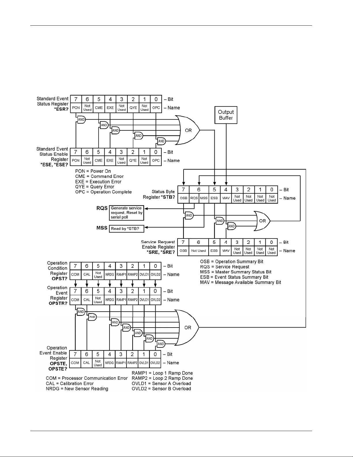
Omega Model CYC325 Temperature Controller User’s Manual
6.1.4.1.3 Enable Registers
Each register set includes an enable register as shown in Figure 6-1. An enable register determines which bits in the
corresponding event register will set the summary bit for the register set in the Status Byte. The user may write to or read
from an enable register. Each event register bit is logically ANDed to the corresponding enable bit of the enable register.
When an enable register bit is set by the user, and the corresponding bit is set in the event register, the output (summary)
of the register will be set, which in turn sets the summary bit of the Status Byte register.
Figure_6-1.bmp
Figure 6-1. Model CYC325 Status System
6-4 Remote Operation
Page 85
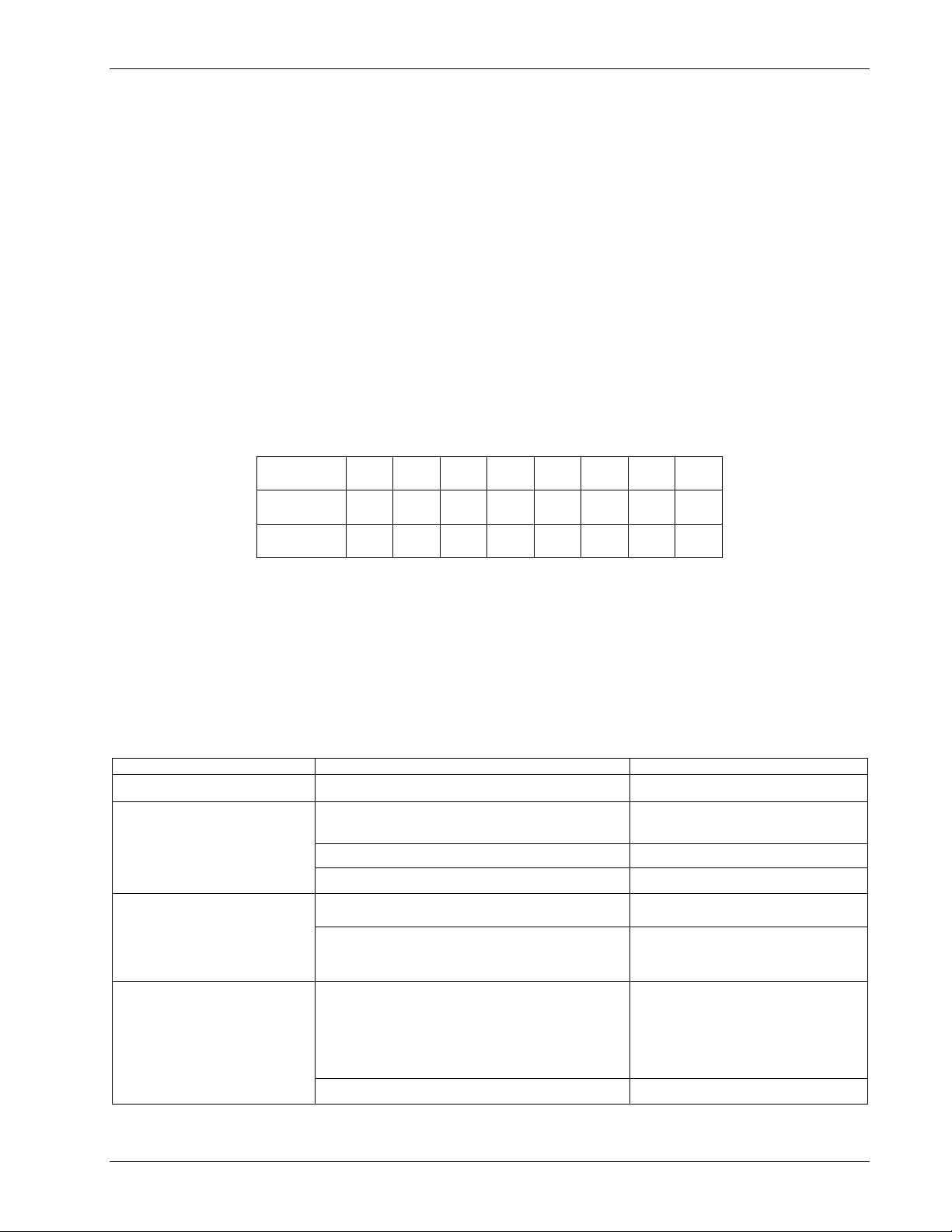
Omega Model CYC325 Temperature Controller User’s Manual
6.1.4.1.4 Status Byte Register
The Status Byte register, typically referred to as the Status Byte, is a non-latching, read-only register that contains all of
the summary bits from the register sets. The status of the summary bits are controlled from the register sets as explained
above. The Status Byte also contains the Request for Service (RQS)/Master Summary Status (MSS) bit. This bit is used
to control the Service Request hardware line on the bus and to report if any of the summary bits are set via the *STB?
command. The status of the RQS/MSS bit is controlled by the summary bits and the Service Request Enable Register.
6.1.4.1.5 Service Request Enable Register
The Service Request Enable Register determines which summary bits in the Status Byte will set the RQS/MSS bit of the
Status Byte. The user may write to or read from the Service Request Enable Register. Each Status Byte summary bit is
logically ANDed to the corresponding enable bit of the Service Request Enable Register. When a Service Request
Enable Register bit is set by the user, and the corresponding summary bit is set in the Status Byte, the RQS/MSS bit of
the Status Byte will be set, which in turn sets the Service Request hardware line on the bus.
6.1.4.1.6 Reading Registers
Any register in the status system may be read using the appropriate query command. Some registers clear when read,
others do not. Refer to Section 6.1.4.1.8. The response to a query will be a decimal value that corresponds to the binaryweighted sum of all bits in the register (Table 6-1). The actual query commands are described later in this section.
Table 6-1. Binary Weighting of an 8-Bit Register
Position B7 B6 B5 B4 B3 B2 B1 B0
Decimal 128 64 32 16 8 4 2 1
Weighting 27 26 25 24 23 22 21 20
6.1.4.1.7 Programming Registers
Example: If bits 0, 2, and 4 are set, a query of the register will return a decimal value of 21 (1+4+16).
The only registers that may be programmed by the user are the enable registers. All other registers in the status system
are read-only registers. To program an enable register send a decimal value that corresponds to the desired binaryweighted sum of all bits in the register, refer to Table 6-1. The actual commands are described later in this section.
6.1.4.1.8 Clearing Registers
The methods to clear each register are detailed in Table 6-2.
Table 6-2. Register Clear Methods
Register Method Example
Condition Registers None — registers are not latched —
Event Registers:
Standard Event Status Register
Operation Event Register
Enable Registers:
Standard Event Status Enable
Register
Operation Event Enable Register
Service Request Enable Register
Status Byte
Query the event register
Send *CLS *CLS (clears both registers)
Power on instrument —
Write 0 to the enable register
Power on instrument —
There are no commands that directly clear the Status
Byte as the bits are non-latching; to clear individual
summary bits, clear the event register that
corresponds to the summary bit — sending *CLS
will clear all event registers which in turn clears the
status byte
Power on instrument —
*ESR? (clears Standard Event Status
register)
*ESE 0 (clears Standard Event Status
Enable register)
If bit 5 (ESB) of the Status Byte is set,
send *ESR? to read the Standard Event
Status Register and bit 5 will clear
Remote Operation 6-5
Page 86
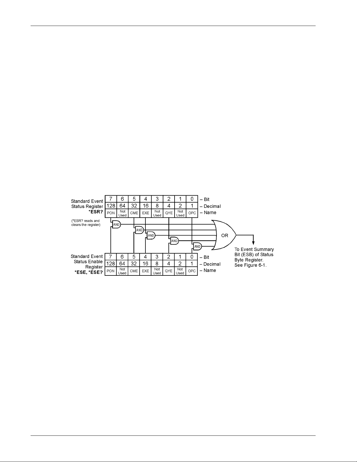
Omega Model CYC325 Temperature Controller User’s Manual
6.1.4.2 Status Reg i ster Sets
As shown in Figure 6-1, there are two register sets in the status system of the Model CYC325: Standard Event Status
Register and Operation Event Register.
6.1.4.2.1 Standard Event Status Register Set
The Standard Event Status Register reports the following interface related instrument events: power on detected,
command syntax errors, command execution errors, query errors, operation complete. Any or all of these events may be
reported in the standard event summary bit through the enable register, see Figure 6-2. The Standard Event Status Enable
command (*ESE) programs the enable register and the query command (*ESE?) reads it. *ESR? reads and clears the
Standard Event Status Register. The used bits of the Standard Event Register are described as follows:
Power On (PON), Bit (7) – This bit is set to indicate an instrument off-on transition.
Command Error (CME), Bit (5) – This bit is set if a command error has been detected since the last reading. This
means that the instrument could not interpret the command due to a syntax error, an unrecognized header,
unrecognized terminators, or an unsupported command.
Execution Error (EXE), Bit (4) – This bit is set if an execution error has been detected. This occurs when the
instrument is instructed to do something not within its capabilities.
Query Error (QYE), Bit (2) – This bit indicated a query error. It occurs rarely and involves loss of data because the
output queue is full.
Operation Complete (OPC), Bit (0) – When *OPC is sent, this bit will be set when the instrument has completed all
pending operations. The operation of this bit is not related to the *OPC? command, which is a separate interface
feature. Refer to Section 6.1.4.3.6 for more information.
Figure_6-2.bmp
Figure 6-2. Standard Event Status Register
6.1.4.2.2 Operation Event Register Set
The Operation Event Register reports the following interface related instrument events: ramp done, new reading,
overload. Any or all of these events may be reported in the operation event summary bit through the enable register,
see Figure 6-3. The Operation Event Enable command (OPSTE) programs the enable register and the query command
(OPSTE?) reads it. OPSTR? reads and clears the Operation Event Register. OPST? reads the Operation Condition
register. The used bits of the Operation Event Register are described as follows:
Processor Communication Error (COM), Bit (7) – This bit is set when the main processor cannot communicate with
the sensor input processor.
Calibration Error (CAL), Bit (6) – This bit is set if the instrument is not calibrated or the calibration data has been
corrupted.
New Sensor Reading (NRDG), Bit (4) – This bit is set when there is a new sensor reading.
Loop 1 Ramp Done (RAMP1), Bit (3) – This bit is set when a loop 1 setpoint ramp is completed.
Loop 2 Ramp Done (RAMP2), Bit (2) – This bit is set when a loop 2 setpoint ramp is completed.
Sensor Overload A (OVLD1), Bit (1) – This bit is set when the sensor A reading is in the overload condition.
Sensor Overload B (OVLD2), Bit (0) – This bit is set when the sensor B reading is in the overload condition.
6-6 Remote Operation
Page 87
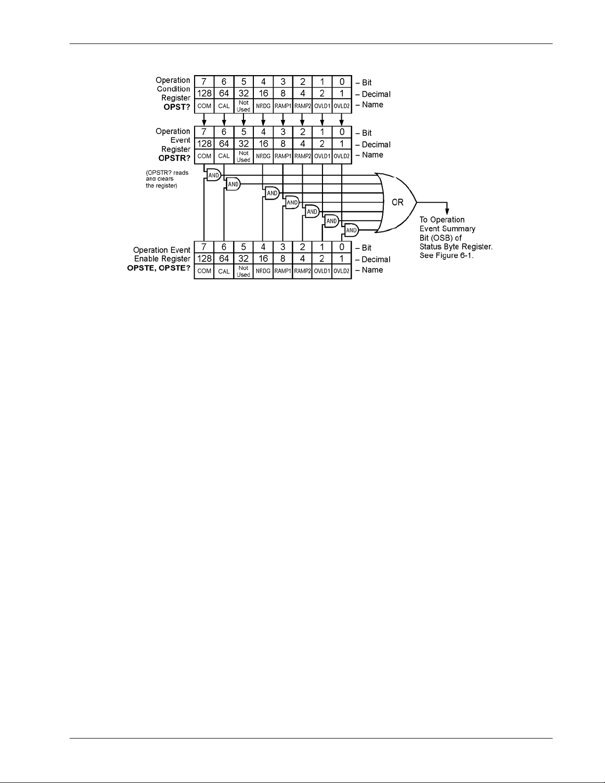
Omega Model CYC325 Temperature Controller User’s Manual
Figure_6-3.bmp
Figure 6-3. Operation Event Register
6.1.4.3 Status B yte and Service Request (SRQ)
As shown in Figure 6-1, the Status Byte Register receives the summary bits from the two status register sets and the
message available summary bit from the output buffer. The status byte is used to generate a service request (SRQ).
The selection of summary bits that will generate an SRQ is controlled by the Service Request Enable Register.
6.1.4.3.1 Status Byte Register
The summary messages from the event registers and output buffer set or clear the summary bits of the Status Byte
Register, see Figure 6-4. These summary bits are not latched. Clearing an event register will clear the corresponding
summary bit in the Status Byte Register. Reading all messages in the output buffer, including any pending queries,
will clear the message available bit. The bits of the Status Byte Register are described as follows:
Operation Summary (OSB), Bit (7) – Set summary bit indicates that an enabled operation event has occurred.
Request Service (RQS)/Master Summary Status (MSS), Bit (6) – This bit is set when a summary bit and the summary
bits corresponding enable bit in the Service Request Enable Register are set. Once set, the user may read and clear the bit
in two different ways, which is why it is referred to as both the RQS and the MSS bit. When this bit goes from low to
high, the Service Request hardware line on the bus is set, this is the RQS function of the bit. Refer to Section 6.1.4.3.3.
In addition, the status of the bit may be read with the *STB? query which returns the binary weighted sum of all bits in
the Status Byte, this is the MSS function of the bit.
Performing a serial poll will automatically clear the RQS function but not the MSS function. A *STB? will read the
status of the MSS bit (along with all of the summary bits), but also will not clear it. To clear the MSS bit, either clear
the event register that set the summary bit or disable the summary bit in the Service Request Enable Register.
Event Summary (ESB), Bit (5) – Set summary bit indicates that an enabled standard event has occurred.
Message Available (MAV), Bit (4) – Set summary bit indicates that a message is available in the output buffer.
Remote Operation 6-7
Page 88
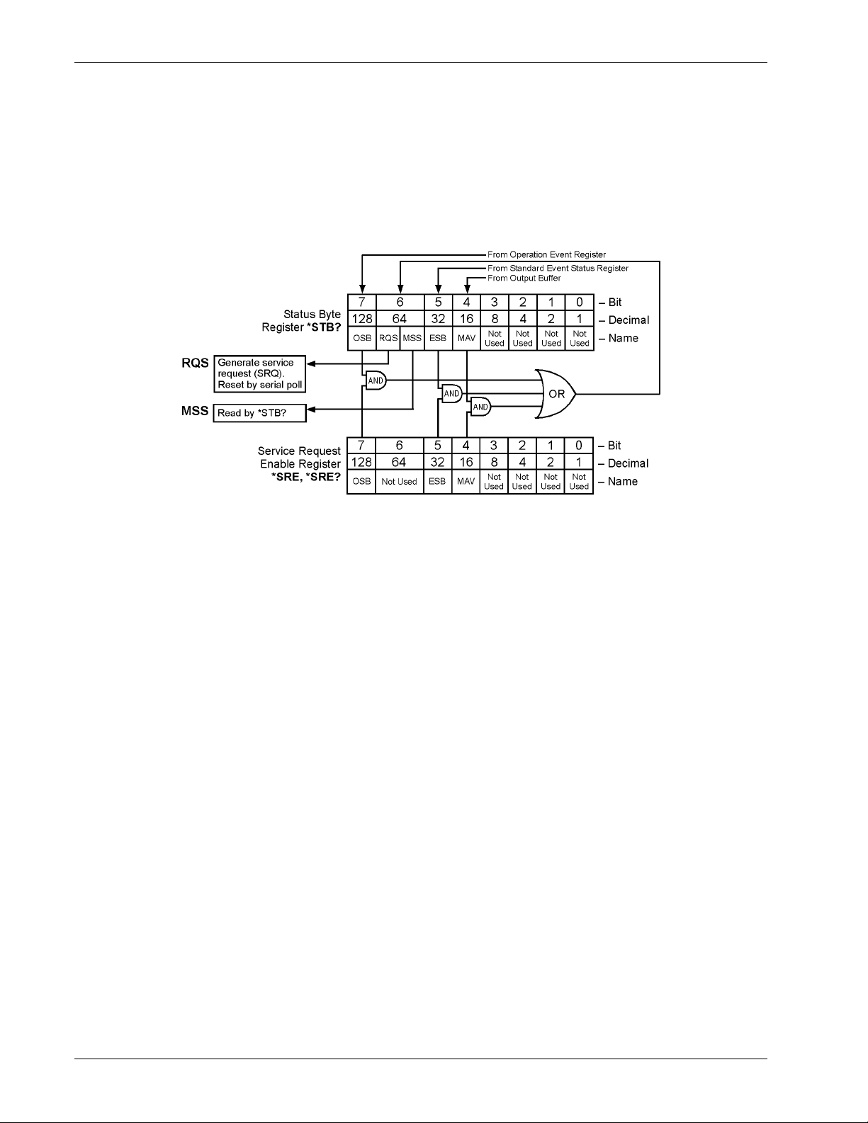
6.1.4.3.2 Service Request Enable Register
Omega Model CYC325 Temperature Controller User’s Manual
The Service Request Enable Register is programmed by the user and determines which summary bits of the Status Byte
may set bit 6 (RQS/MSS) to generate a Service Request. Enable bits are logically ANDed with the corresponding
summary bits, see Figure 6-4. Whenever a summary bit is set by an event register and its corresponding enable bit is set
by the user, bit 6 will set to generate a service request. The Service Request Enable command (*SRE) programs the
Service Request Enable Register and the query command (*SRE?) reads it. Reading the Service Request Enable Register
will not clear it. The register may be cleared by the user by sending *SRE 0.
Figure_6-4.bmp
Figure 6-4. Status Byte Register and Service Request Enable Register
6.1.4.3.3 Using Service Request (SRQ) and Serial Poll
When a Status Byte summary bit (or MAV bit) is enabled by the Service Request Enable Register and goes from 0 to 1,
bit 6 (RQS/MSS) of the status byte will be set. This will send a service request (SRQ) interrupt message to the bus
controller. The user program may then direct the bus controller to serial Poll the instruments on the bus to identify which
one requested service (the one with bit 6 set in its status byte).
Serial polling will automatically clear RQS of the Status Byte Register. This allows subsequent serial polls to monitor bit
6 for an SRQ occurrence generated by other event types. After a serial poll, the same event or any event that uses the
same Status Byte summary bit, will not cause another SRQ unless the event register that caused the first SRQ has been
cleared, typically by a query of the event register.
The serial poll does not clear MSS. The MSS bit stays set until all enabled Status Byte summary bits are cleared,
typically by a query of the associated event register — refer to Section 6.1.4.3.4.
The programming example in Table 6-3 initiates an SRQ when a command error is detected by the instrument.
6-8 Remote Operation
Page 89
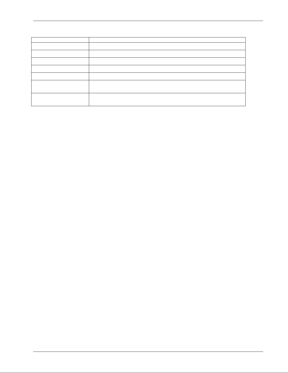
Command or Operation Description
Omega Model CYC325 Temperature Controller User’s Manual
Table 6-3. Programming Example to Generate an SRQ
*ESR? Read and clear the Standard Event Status Register.
*ESE 32 Enable the Command Error (CME) bit in the Standard Event Status Register
*SRE 32 Enable the Event Summary Bit (ESB) to set the RQS
*ABC Send improper command to instrument to generate a command error
Monitor bus Monitor the bus until the Service Request interrupt (SRQ) is sent.
Initiate Serial Poll
Serial Poll the bus to determine which instrument sent the interrupt and clear the
RQS bit in the Status Byte.
*ESR?
Read and clear the Standard Event Status Register allowing an SRQ to be
generated on another command error.
6.1.4.3.4 Using Status Byte Query (*STB?)
The Status Byte Query (*STB?) command is similar to a Serial Poll except it is processed like any other instrument
command.. The *STB? command returns the same result as a Serial Poll except that the Status Byte bit 6 (RQS/MSS) is
not cleared. In this case bit 6 is considered the MSS bit. Using the *STB? command does not clear any bits in the Status
Byte Register.
6.1.4.3.5 Using the Message Available (MAV) bit
Status Byte summary bit 4 (MAV) indicates that data is available to read into your bus controller. This message may be
used to synchronize information exchange with the bus controller. The bus controller can, for example, send a query
command to the Model CYC325 and then wait for MAV to set. If the MAV bit has been enabled to initiate an SRQ, the
user’s program can direct the bus controller to look for the SRQ leaving the bus available for other use. The MAV bit
will be clear whenever the output buffer is empty.
6.1.4.3.6 Using Operation Complete (*OPC) and Operation Complete Query (*OPC?)
The Operation Complete (*OPC) and Operation Complete Query (*OPC?) are both used to indicate when pending
device operations complete. However, the commands operate with two distinct methods.
The *OPC command is used in conjunction with bit 0 (OPC) of the Standard Event Status Register. If *OPC is sent as
the last command in a command sequence, bit 0 will be set when the instrument completes the operation that was
initiated by the command sequence. Additional commands may be sent between the instrument and the bus controller
while waiting for the initial pending operation to complete. A typical use of this function would be to enable the OPC bit
to generate an SRQ and include the *OPC command when programming the instrument. The bus controller could then
be instructed to look for an SRQ allowing additional communication with the instrument while the initial process
executes.
The *OPC? query has no interaction with bit 0 (OPC) of the Standard Event Status Register. If the *OPC? query is sent
at the end of a command sequence, the bus will be held until the instrument completes the operation that was initiated by
the command sequence. Additional commands (except *RST) should not be sent until the operation is complete, as
erratic operation will occur. Once the sequence is complete a 1 will be placed in the output buffer. This function is
typically used to signal a completed operation without monitoring the SRQ. It is also used when it is important to prevent
any additional communication on the bus during a pending operation.
Remote Operation 6-9
Page 90

Omega Model CYC325 Temperature Controller User’s Manual
6.1.5 IEEE Interface Example Program
A Visual Basic program is included to illustrate the IEEE-488 communication functions of the instrument. Instructions
for setting up the IEEE-488 board is included in Section 6.1.5.1. Refer to Section 6.1.5.2 for instructions on how to set
up the program. The Visual Basic code is provided in Table 6-2. A description of program operation is provided in
Section 6.1.5.3. While the hardware and software required to produce and implement these programs not included with
the instrument, the concepts illustrated apply to most applications.
6.1.5.1 IEEE-488 Inter face Board Installation for Visual Basic Program
This procedure works for Plug and Play General Purpose Interface Board (GPIB) hardware and software for
Windows 98/95. This example uses the AT-GPIB/TNT GPIB card.
1. Install the GPIB plug and play software and hardware using National Instruments instructions.
2. Verify that the following files have been installed to the Windows System folder:
a. gpib-32.dll
b. gpib.dll
c. gpib32ft.dll
Files b and c will support 16-bit Windows GPIB applications if any are being used.
3. Locate the following files and make note of their location. These files will be used during the development process
of a Visual Basic program.
a. Niglobal.bas
b. Vbib-32.bas
NOTE: If the files in Steps 2 and 3 are not installed on your computer, they may be copied from your
National Instruments setup disks or they may be downloaded from www.ni.com.
4. Configure the GPIB by selecting the System icon in the Windows 98/95 Control Panel located under Settings on the
Start Menu. Configure the GPIB Settings as shown in Figure 6-5. Configure the DEV12 Device Template as shown
in Figure 6-6. Be sure to check the Readdress box.
6.1.5.2 Visual Basic IEEE-488 Interface Program Setup
This IEEE-488 interface program works with Visual Basic 6.0 (VB6) on an IBM PC (or compatible) with a Pentiumclass processor. A Pentium 90 or higher is recommended, running Windows 95 or better. It assumes your IEEE-488
(GPIB) card is installed and operating correctly (refer to Section 6.1.5.1). Use the following procedure to develop the
IEEE-488 Interface Program in Visual Basic.
1. Start VB6.
2. Choose Standard EXE and select Open.
3. Resize form window to desired size.
4. On the Project Menu, select Add Module, select the Existing tab, then navigate to the location on your computer to
add the following files: Niglobal.bas and Vbib-32.bas.
5. Add controls to form:
a. Add three Label controls to the form.
b. Add two TextBox controls to the form.
c. Add one CommandButton control to the form.
6. On the View Menu, select Properties Window.
6-10 Remote Operation
Page 91
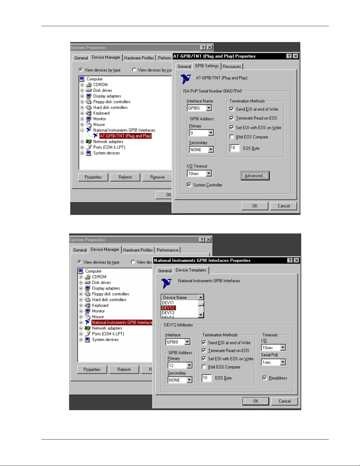
Omega Model CYC325 Temperature Controller User’s Manual
VB_GPIB_1.bmp
Figure 6-5. GPIB Setting Configuration
VB_GPIB_2.bmp
Figure 6-6. DEV 12 Device Template Configuration
Remote Operation 6-11
Page 92
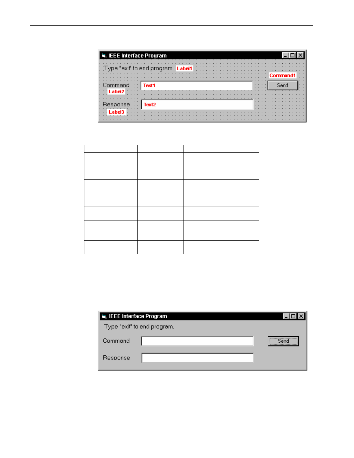
p
Visual Basic IEEE-488 Interface Program Setup (Continued)
Omega Model CYC325 Temperature Controller User’s Manual
7. In the Properties
window, use the
dropdown list to
select between the
different controls
of the current
project.
8. Set the properties
of the controls as
defined in
Table 6-4.
9. Save the program.
VB_GPIB_3.bm
Table 6-4. IEEE-488 Interface Program Control Properties
Current Name Property New Value
Label1 Name
Caption
Label2 Name
Caption
Label3 Name
Caption
Text1 Name
Text
Text2 Name
Text
Command1 Name
Caption
Default
Form1 Name
Caption
lblExitProgram
Type “exit” to end program.
lblCommand
Command
lblResponse
Response
txtCommand
<blank>
txtResponse
<blank>
cmdSend
Send
True
frmIEEE
IEEE Interface Program
10. Add code (provided in Table 6-5).
a. In the Code Editor window, under the Object dropdown list, select (General). Add the statement: Public gSend
as Boolean
b. Double Click on cmdSend. Add code segment under Private Sub cmdSend_Click( ) as shown in Table 6-5.
c. In the Code Editor window, under the Object dropdown list, select Form. Make sure the Procedure dropdown
list is set at Load. The Code window should have written the segment of code: Private Sub Form_Load( ). Add
the code to this subroutine as shown in Table 6-5.
11. Save the program.
12. Run the program.
The program
should resemble
the window to the
right.
13. Type in a
command or query
in the Command
box as described in
VB_GPIB_4.bmp
Section 6.1.5.5.
14. Press Enter or select the Send button with the mouse to send command.
15. Type Exit and press Enter to quit.
6-12 Remote Operation
Page 93

Omega Model CYC325 Temperature Controller User’s Manual
Table 6-5. Visual Basic IEEE-488 Interface Program
Public gSend As Boolean 'Global used for Send button state
Private Sub cmdSend_Click() 'Routine to handle Send button press
gSend = True 'Set Flag to True
End Sub
Private Sub Form_Load() 'Main code section
Dim strReturn As String 'Used to return response
Dim term As String 'Terminators
Dim strCommand As String 'Data string sent to instrument
Dim intDevice As Integer 'Device number used with IEEE
frmIEEE.Show 'Show main window
term = Chr(13) & Chr(10) 'Terminators are <CR><LF>
strReturn = "" 'Clear return string
Call ibdev(0, 12, 0, T10s, 1, &H140A, intDevice) 'Initialize the IEEE device
Do
Do 'Wait loop
DoEvents 'Give up processor to other events
Loop Until gSend = True 'Loop until Send button pressed
gSend = False 'Set Flag as False
strCommand = frmIEEE.txtCommand.Text 'Get Command
strReturn = "" 'Clear response display
strCommand = UCase(strCommand) 'Set all characters to upper case
If strCommand = "EXIT" Then 'Get out on EXIT
End
End If
Call ibwrt(intDevice, strCommand & term) 'Send command to instrument
If (ibsta And EERR) Then 'Check for IEEE errors
'do error handling if needed 'Handle errors here
End If
If InStr(strCommand, "?") <> 0 Then 'Check to see if query
strReturn = Space(100) 'Build empty return buffer
Call ibrd(intDevice, strReturn) 'Read back response
If (ibsta And EERR) Then 'Check for IEEE errors
'do error handling if needed 'Handle errors here
End If
If strReturn <> "" Then 'Check if empty string
strReturn = RTrim(strReturn) 'Remove extra spaces and Terminators
Do While Right(strReturn, 1) = Chr(10) Or Right(strReturn, 1) = Chr(13)
strReturn = Left(strReturn, Len(strReturn) - 1)
Loop
Else
strReturn = "No Response" 'Send No Response
End If
frmIEEE.txtResponse.Text = strReturn 'Put response in text on main form
End If
Loop
End Sub
Remote Operation 6-13
Page 94

6.1.5.3 Program Operation
Omega Model CYC325 Temperature Controller User’s Manual
Once the program is running, try the following commands and observe the response of the instrument. Input from the
user is shown in bold and terminators are added by the program. The word [term] indicates the required terminators
included with the response.
ENTER COMMAND? *IDN? Identification query. Instrument will return a string identifying
itself.
RESPONSE: LSCI,MODEL325,1234567,1.0/1.0[term]
ENTER COMMAND? KRDG? Temperature reading in kelvin query. Instrument will return a
string with the present temperature reading.
RESPONSE: +273.15[term]
ENTER COMMAND? RANGE 1,0 Heater range command. Instrument will turn off the Loop 1
heater. No response will be sent.
ENTER COMMAND? RANGE? 1 Heater range query. Instrument will return a string with the
present Loop 1 heater range setting.
RESPONSE: 0[term]
ENTER COMMAND? RANGE 1,1;RANGE? 1 Heater range command followed by a query. Instrument will
change to Loop 1 heater Low setting then return a string
RESPONSE: 1[term] with the present setting.
The following are additional notes on using either IEEE-488 Interface program.
• If you enter a correctly spelled query without a “?,” nothing will be returned. Incorrectly spelled commands and
queries are ignored. Commands and queries and should have a space separating the command and associated
parameters.
• Leading zeros and zeros following a decimal point are not needed in a command string, but are sent in response to a
query. A leading “+” is not required but a leading “–” is required.
6.1.6 Troubleshooting
New Installation
1. Check instrument address.
2. Always send terminators.
3. Send entire message string at one time including terminators.
4. Send only one simple command at a time until communication is established.
5. Be sure to spell commands correctly and use proper syntax.
6. Attempt both 'Talk' and 'Listen' functions. If one works but not the other, the hardware connection is working, so
look at syntax, terminators, and command format.
7. If only one message is received after resetting the interface, check the “repeat addressing” setting. It should be
enabled.
Old Installation No Longer Working
1. Power instrument off then on again to see if it is a soft failure.
2. Power computer off then on again to see if the IEEE card is locked up.
3. Verify that the address has not been changed on the instrument during a memory reset.
4. Check all cable connections.
Intermittent Lockups
1. Check cable connections and length.
2. Increase delay between all commands to 50 ms to make sure instrument is not being overloaded.
6-14 Remote Operation
Page 95

Omega Model CYC325 Temperature Controller User’s Manual
6.2 SERIAL INTERFACE OVERVIEW
The serial interface used in the Model CYC325 is commonly referred to as an RS-232C interface. RS-232C is a standard
of the Electronics Industries Association (EIA) that describes one of the most common interfaces between computers and
electronic equipment. The RS-232C standard is quite flexible and allows many different configurations. However, any
two devices claiming RS-232C compatibility cannot necessarily be plugged together without interface setup. The
remainder of this section briefly describes the key features of a serial interface that are supported by the instrument.
A customer-supplied computer with similarly configured interface port is required to enable communication.
6.2.1 Physical Connection
The Model CYC325 has a 9-pin D-subminiature plug on the rear panel for serial communication. The original RS-232C
standard specifies 25 pins but both 9- and 25-pin connectors are commonly used in the computer industry. Many third
party cables exist for connecting the instrument to computers with either 9- or 25-pin connectors. Section 8.7.1 gives the
most common pin assignments for 9- and 25-pin connectors. Please note that not all pins or functions are supported by
the Model CYC325.
The instrument serial connector is the plug half of a mating pair and must be matched with a socket on the cable. If a
cable has the correct wiring configuration but also has a plug end, a “gender changer” can be used to mate two plug ends
together.
The letters DTE near the interface connector stand for Data Terminal Equipment and indicate the pin connection of the
directional pins such as transmit data (TD) and receive data (RD). Equipment with Data Communications Equipment
(DCE) wiring can be connected to the instrument with a straight through cable. As an example, Pin 3 of the DTE
connector holds the transmit line and Pin 3 of the DCE connector holds the receive line so the functions complement.
It is likely both pieces of equipment are wired in the DTE configuration. In this case Pin 3 on one DTE connector (used
for transmit) must be wired to Pin 2 on the other (used for receive). Cables that swap the complementing lines are called
null modem cables and must be used between two DTE wired devices. Null modem adapters are also available for use
with straight through cables. Section 8.7.1 illustrates suggested cables that can be used between the instrument and
common computers.
The instrument uses drivers to generate the transmission voltage levels required by the RS-232C standard. These
voltages are considered safe under normal operating conditions because of their relatively low voltage and current limits.
The drivers are designed to work with cables up to 50 feet in length.
6.2.2 Hardware Support
The Model CYC325 interface hardware supports the following features. Asynchronous timing is used for the individual
bit data within a character. This timing requires start and stop bits as part of each character so the transmitter and receiver
can resynchronize between each character.
Half duplex transmission allows the
instrument to be either a transmitter or a
receiver of data but not both at the same time.
Communication speeds of 9600, 19200,
38400, 57600 baud are supported. The baud
rate is the only interface parameter that can be
changed by the user.
Hardware handshaking is not supported by the
instrument. Handshaking is often used to
guarantee that data message strings do not
collide and that no data is transmitted before
the receiver is ready. In this instrument,
appropriate software timing substitutes for
hardware handshaking. User programs must
take full responsibility for flow control and
timing as described in Section 6.2.5.
Connector Type:
Connector Wiring:
Voltage Levels:
Transmission Distance:
Timing Format:
Transmission Mode:
Baud Rate:
Handshake:
Character Bits:
Parity:
Terminators:
Command Rate:
Table 6-6. Serial Interface Specifications
9-pin D-style connector plug
DTE
EIA RS-232C specified
50 ft maximum
Asynchronous
Half duplex
9600, 19200, 38400, 57600
Software timing
1 Start, 7 Data, 1 Parity, 1 Stop
Odd
CR(0DH) LF(0AH)
20 commands per second maximum
Remote Operation 6-15
Page 96

Omega Model CYC325 Temperature Controller User’s Manual
6.2.3 Character Format
A character is the smallest piece of information that can be transmitted by the interface. Each character is 10 bits long
and contains data bits, bits for character timing and an error detection bit. The instrument uses 7 bits for data in the
ASCII format. One start bit and one stop bit are necessary to synchronize consecutive characters. Parity is a method of
error detection. One parity bit configured for odd parity is included in each character.
ASCII letter and number characters are used most often as character data. Punctuation characters are used as delimiters
to separate different commands or pieces of data. Two special ASCII characters, carriage return (CR 0DH) and line feed
(LF 0AH), are used to indicate the end of a message string.
6.2.4 Message Strings
A message string is a group of characters assembled to perform an interface function. There are three types of message
strings commands, queries and responses. The computer issues command and query strings through user programs, the
instrument issues responses. Two or more command strings can be chained together in one communication but they must
be separated by a semi-colon (;). Only one query is permitted per communication but it can be chained to the end of a
command. The total communication string must not exceed 64 characters in length.
A command string is issued by the computer and instructs the instrument to perform a function or change a parameter
setting. The format is:
<command mnemonic><space><parameter data><terminators>.
Command mnemonics and parameter data necessary for each one is described in Section 6.3. Terminators must be sent
with every message string.
A query string is issued by the computer and instructs the instrument to send a response. The query format is:
<query mnemonic><?><space><parameter data><terminators>.
Query mnemonics are often the same as commands with the addition of a question mark. Parameter data is often
unnecessary when sending queries. Query mnemonics and parameter data if necessary is described in Section 6.3.
Terminators must be sent with every message string. The computer should expect a response very soon after a query is
sent.
A response string is the instruments response or answer to a query string. The instrument will respond only to the last
query it receives. The response can be a reading value, status report or the present value of a parameter. Response data
formats are listed along with the associated queries in Section 6.3. The response is sent as soon as possible after the
instrument receives the query. Typically it takes 10 ms for the instrument to begin the response. Some responses take
longer.
6.2.5 Message Flow Control
It is important to remember that the user program is in charge of the serial communication at all times. The instrument
cannot initiate communication, determine which device should be transmitting at a given time or guarantee timing
between messages. All of this is the responsibility of the user program.
When issuing commands only the user program should:
• Properly format and transmit the command including terminators as one string.
• Guarantee that no other communication is started for 50 ms after the last character is transmitted.
• Not initiate communication more than 20 times per second.
When issuing queries or queries and commands together the user program should:
• Properly format and transmit the query including terminators as one string.
• Prepare to receive a response immediately.
• Receive the entire response from the instrument including the terminators.
• Guarantee that no other communication is started during the response or for 50 ms after it completes.
• Not initiate communication more than 20 times per second.
Failure to follow these simple rules will result in inability to establish communication with the instrument or intermittent
failures in communication.
6-16 Remote Operation
Page 97
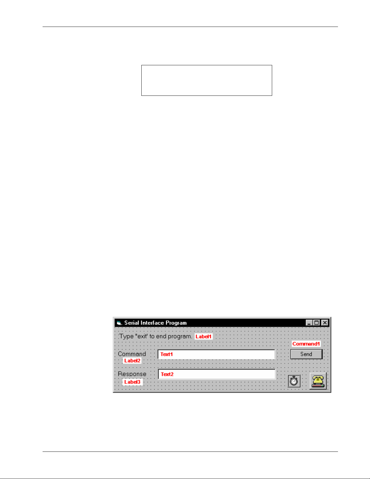
Omega Model CYC325 Temperature Controller User’s Manual
6.2.6 Changing Baud Rate
To use the serial interface, you must first set the baud rate. Press Interface key to display the following screen.
Select−With−°®
Baud−−9600
Press the s or t key to cycle through the choices of 9600, 19200, 38400, 57600 baud. Press the Enter key to accept the
new number.
6.2.7 Serial Interface Example Program
A Visual Basic program is included to illustrate the serial communication functions of the instrument. Refer to
Section 6.2.7.1 for instructions on how to set up the program. The Visual Basic code is provided in Table 6-8.
A description of program operation is provided in Section 6.2.7.2. While the hardware and software required to produce
and implement these programs not included with the instrument, the concepts illustrated apply to most applications.
6.2.7.1 Visual Basic Serial Interface Program Setup
The serial interface program works with Visual Basic 6.0 (VB6) on an IBM PC (or compatible) with a Pentium-class
processor. A Pentium 90 or higher is recommended, running Windows 95 or better, with a serial interface. It uses the
COM1 communications port at 9600 baud. Use the following procedure to develop the serial interface program in Visual
Basic.
1. Start VB6.
2. Choose Standard EXE and select Open.
3. Resize form window to desired size.
4. On the Project Menu, click Components to bring up a list of additional controls available in VB6.
5. Scroll through the controls and select Microsoft Comm Control 6.0. Select OK. In the toolbar at the left of the
screen, the Comm Control will have appeared as a telephone icon.
6. Select the Comm control and add it to the form.
7. Add controls to form:
a. Add three Label controls to the form.
b. Add two TextBox controls to the form.
c. Add one CommandButton control to the form.
d. Add one Timer control to the form.
8. On the View Menu, select Properties Window.
9. In the Properties
window, use the
dropdown list to
select between the
different controls
of the current
project.
10. Set the properties
of the controls as
defined in
Table 6-7.
11. Save the program.
VB_Serial_1.bmp
Remote Operation 6-17
Page 98
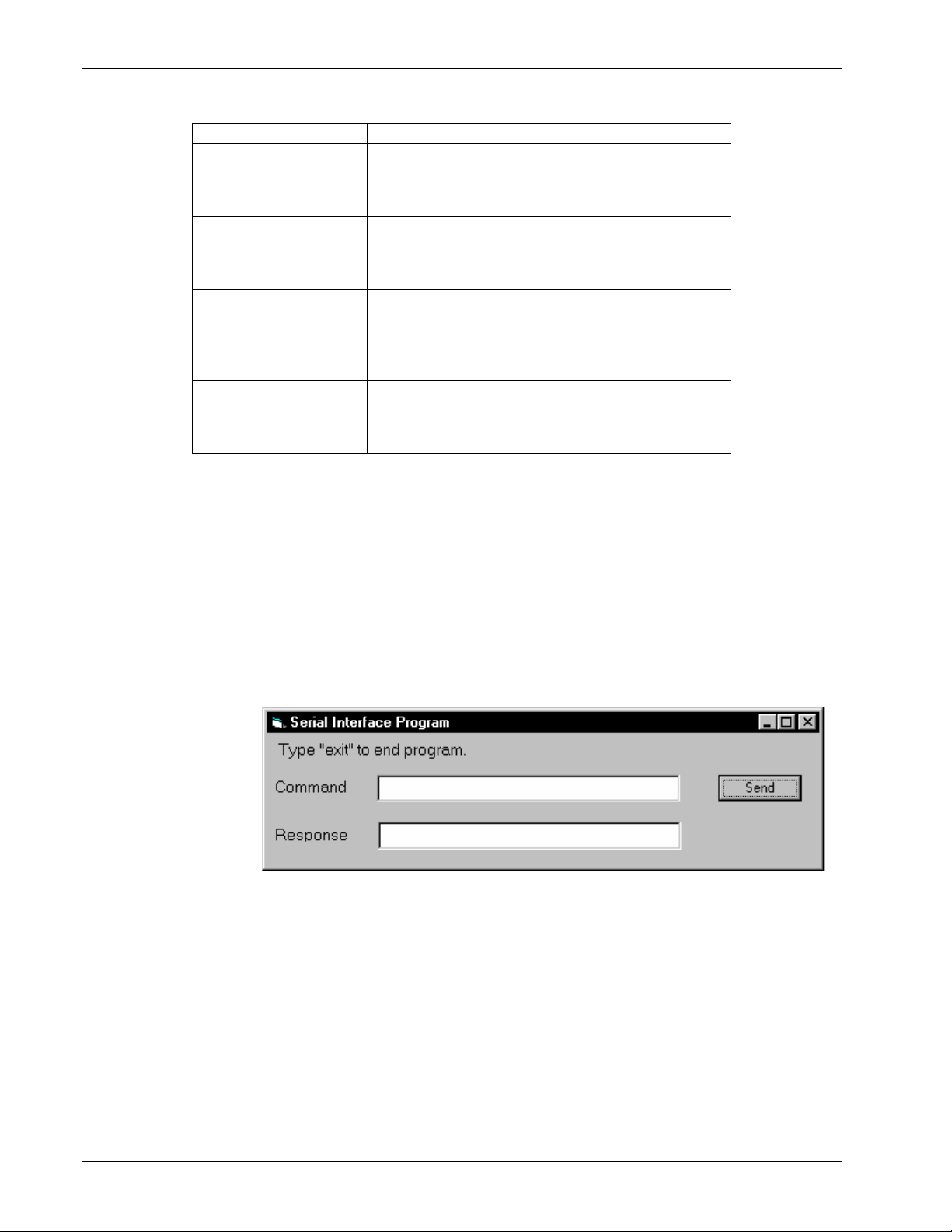
Current Name Property New Value
Label1 Name
Label2 Name
Label3 Name
Text1 Name
Text2 Name
Command1 Name
Form1 Name
Timer1 Enabled
Omega Model CYC325 Temperature Controller User’s Manual
Table 6-7. Serial Interface Program Control Properties
lblExitProgram
Caption
Type “exit” to end program.
lblCommand
Caption
Command
lblResponse
Caption
Response
txtCommand
Text
<blank>
txtResponse
Text
<blank>
cmdSend
Caption
Default
Send
True
frmSerial
Caption
Serial Interface Program
False
Interval
10
12. Add code (provided in Table 6-8).
a. In the Code Editor window, under the Object dropdown list, select (General). Add the statement: Public gSend
as Boolean.
b. Double click on cmdSend. Add code segment under Private Sub cmdSend_Click( ) as shown in Table 6-8.
c. In the Code Editor window, under the Object dropdown list, select Form. Make sure the Procedure dropdown
list is set at Load. The Code window should have written the segment of code: Private Sub Form_Load( ).
Add the code to this subroutine as shown in Table 6-8.
d. Double click on the Timer control. Add code segment under Private Sub Timer1_Timer() as shown in
Table 6-8.
e. Make adjustments to code if different com port settings are being used.
13. Save the program.
14. Run the program.
The program
should resemble
the window to the
right.
15. Type in a command
or query in the
Command box as
described in
Section 6.2.7.3.
16. Press Enter or
VB_Serial_2.bmp
select the Send
button with the mouse to send command.
17. Type Exit and press Enter to quit.
6-18 Remote Operation
Page 99

Omega Model CYC325 Temperature Controller User’s Manual
Table 6-8. Visual Basic Serial Interface Program
Public gSend As Boolean 'Global used for Send button state
Private Sub cmdSend_Click() 'Routine to handle Send button press
gSend = True 'Set Flag to True
End Sub
Private Sub Form_Load() 'Main code section
Dim strReturn As String 'Used to return response
Dim strHold As String 'Temporary character space
Dim Term As String 'Terminators
Dim ZeroCount As Integer 'Counter used for Timing out
Dim strCommand As String 'Data string sent to instrument
frmSerial.Show 'Show main window
Term = Chr(13) & Chr(10) 'Terminators are <CR><LF>
ZeroCount = 0 'Initialize counter
strReturn = "" 'Clear return string
strHold = "" 'Clear holding string
If frmSerial.MSComm1.PortOpen = True Then 'Close serial port to change settings
frmSerial.MSComm1.PortOpen = False
End If
frmSerial.MSComm1.CommPort = 1 'Example of Comm 1
frmSerial.MSComm1.Settings = "9600,o,7,1" 'Example of 9600 Baud,Parity,Data,Stop
frmSerial.MSComm1.InputLen = 1 'Read one character at a time
frmSerial.MSComm1.PortOpen = True 'Open port
Do
Do 'Wait loop
DoEvents 'Give up processor to other events
Loop Until gSend = True 'Loop until Send button pressed
gSend = False 'Set Flag as false
strCommand = frmSerial.txtCommand.Text 'Get Command
strReturn = "" 'Clear response display
strCommand = UCase(strCommand) 'Set all characters to upper case
If strCommand = "EXIT" Then 'Get out on EXIT
End
End If
frmSerial.MSComm1.Output = strCommand & Term 'Send command to instrument
If InStr(strCommand, "?") <> 0 Then 'Check to see if query
While (ZeroCount < 20) And (strHold <> Chr$(10)) 'Wait for response
If frmSerial.MSComm1.InBufferCount = 0 Then 'Add 1 to timeout if no character
frmSerial.Timer1.Enabled = True
Do
DoEvents 'Wait for 10 millisecond timer
Loop Until frmSerial.Timer1.Enabled = False
ZeroCount = ZeroCount + 1 'Timeout at 2 seconds
Else
ZeroCount = 0 'Reset timeout for each character
strHold = frmSerial.MSComm1.Input 'Read in one character
strReturn = strReturn + strHold 'Add next character to string
End If
Wend 'Get characters until terminators
If strReturn <> "" Then 'Check if string empty
strReturn = Mid(strReturn, 1, InStr(strReturn, Term) – 1) 'Strip terminators
Else
strReturn = "No Response" 'Send No Response
End If
frmSerial.txtResponse.Text = strReturn 'Put response in textbox on main form
strHold = "" 'Reset holding string
ZeroCount = 0 'Reset timeout counter
End If
Loop
End Sub
Private Sub Timer1_Timer() 'Routine to handle Timer interrupt
frmSerial.Timer1.Enabled = False 'Turn off timer
End Sub
Remote Operation 6-19
Page 100

6.2.7.2 Program Operation
Omega Model CYC325 Temperature Controller User’s Manual
Once the program is running, try the following commands and observe the response of the instrument. Input from the
user is shown in bold and terminators are added by the program. The word [term] indicates the required terminators
included with the response.
ENTER COMMAND? *IDN? Identification query. Instrument will return a string identifying
itself.
RESPONSE: LSCI,MODEL325,1234567,1.0/1.0[term]
ENTER COMMAND? KRDG? Temperature reading in kelvin query. Instrument will return a
string with the present temperature reading.
RESPONSE: +273.15[term]
ENTER COMMAND? RANGE 0 Heater range command. Instrument will turn off the heater. No
response will be sent.
ENTER COMMAND? RANGE? Heater range query. Instrument will return a string with the
present heater range setting.
RESPONSE: 0[term]
ENTER COMMAND? RANGE 1;RANGE? Heater range command followed by a query. Instrument will
change to heater Low setting then return a string
RESPONSE: 1[term] with the present setting.
The following are additional notes on using either serial interface program.
• If you enter a correctly spelled query without a “?,” nothing will be returned. Incorrectly spelled commands and
queries are ignored. Commands and queries and should have a space separating the command and associated
parameters.
• Leading zeros and zeros following a decimal point are not needed in a command string, but they will be sent in
response to a query. A leading “+” is not required but a leading “–” is required.
6.2.8 Troubleshooting
New Installation
1. Check instrument baud rate.
2. Make sure transmit (TD) signal line from the instrument is routed to receive (RD) on the computer and vice versa.
(Use a null modem adapter if not.)
3. Always send terminators.
4. Send entire message string at one time including terminators. (Many terminal emulation programs do not.)
5. Send only one simple command at a time until communication is established.
6. Be sure to spell commands correctly and use proper syntax.
Old Installation No Longer Working
1. Power instrument off then on again to see if it is a soft failure.
2. Power computer off then on again to see if communication port is locked up.
3. Verify that baud rate has not been changed on the instrument during a memory reset.
4. Check all cable connections.
Intermittent Lockups
1. Check cable connections and length.
2. Increase delay between all commands to 100 ms to make sure instrument is not being overloaded.
6-20 Remote Operation
 Loading...