

Page 1
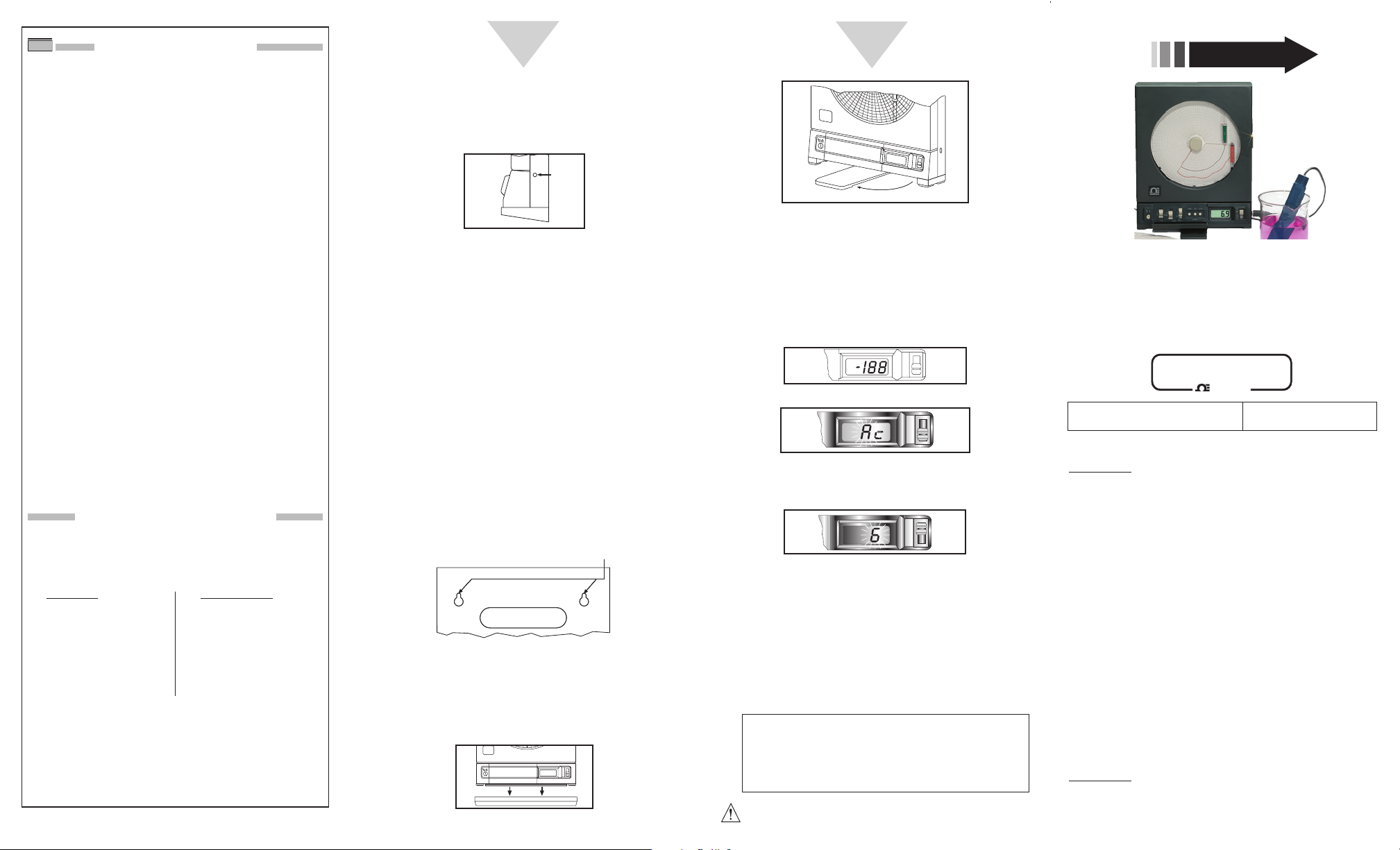
Figure 11. Stabilizing Arm Use
Powering Up the Unit
1. Remove the sensor from the clip (but leave the sensor
connected to the recorder). Examine the code on the
handle (you will compare this code with that displayed on
the recorder LCD display).
2. Turn the power switch (marked “PWR” – behind the
Control Panel Door) to the ON (“|”) position. The
recorder beeps once and then the LCD displays:
Figure 12. First LCD Display
Figure 13. Temperature Code on Display
This two-character code, made up of numbers and/or
letters 0, 1, ... 9, a, b, and c (your code will be AC).
Figure 14. pH Code on Display
This single-character code, a number or a letter 0, 1, ... 9, a, b, or c
(your code will be 6). If either of these codes do not match,
consult the manual for more information. If you want to see the
codes again, turn the recorder OFF and then ON again.
After the codes appear, the LCD displays the current
temperature in °C and pH depending on the position of the
pH/°C switch. At the same time the pens, one at a time, move
to the right a short distance and then move to the left to the
zero position. Then both pens one at a time move to the correct
positions. The recorder is now fully operational.
pH
°C
pH
°C
pH
°C
LO BAT
Swing
H
U
M
I
D
I
T
Y
pH
°C
Connecting ac Power
1. Plug in the connector on the ac adaptor to the ac
power jack on the side of the recorder as shown
in Figure 8.
Figure 8. ac Power Jack Location Detail
2. Connect the ac adaptor to a 110Vac or 220Vac
outlet as appropriate. The ac adaptor has a 6 foot
(2 meter) cable.
Recorder Placement
As shipped, the recorder is set up for wall mounting
(there is a decorative cover at the bottom of the
recorder which remains in place for wall mounting - it
comes off for bench top use).
Mount the Recorder on the Wall
1. Use the template provided in the wall mounting kit
to locate the mounting holes.
2. Drill the holes.
3. Place anchors and screws in the holes.
4. Hang the recorder using the keyhole slot mounting
holes provided on the back side of the recorder.
Refer to Figure 9.
Figure 9. Mounting Holes on the Rear
of the Recorder
Setting the Recorder on a Bench Top
Remove the decorative foot cover (refer to Figure 10),
and swing out the stabilizing arm to further steady the
recorder (refer to Figure 11).
Figure 10. Foot Cover Removal
pH
°C
Mounting Holes
WARRANTY/DISCLAIMER
OMEGA ENGINEERING, INC. warrants this unit to be free of defects in
materials and workmanship for a period of 13 months from date of
purchase. OMEGA Warranty adds an additional one (1) month grace period
to the normal one (1) year product warranty to cover handling and
shipping time. This ensures that OMEGA’s customers receive maximum
coverage on each product.
If the unit should malfunction, it must be returned to the factory for
evaluation. OMEGA’s Customer Service Department will issue an Authorized
Return (AR) number immediately upon phone or written request. Upon
examination by OMEGA, if the unit is found to be defective it will be repaired
or replaced at no charge. OMEGA'S WARRANTY does not apply to defects
resulting from any action of the purchaser, including but not limited to
mishandling, improper interfacing, operation outside of design limits,
improper repair, or unauthorized modification. This WARRANTY is VOID if
the unit shows evidence of having been tampered with or shows evidence of
being damaged as a result of excessive corrosion; or current, heat, moisture
or vibration; improper specification; misapplication; misuse or other
operating conditions outside of OMEGA’s control. Components which wear
are not warranted, including but not limited to contact points, fuses,
and triacs.
OMEGA is pleased to offer suggestions on the use of its various
products. However, OMEGA neither assumes responsibility for any
omissions or errors nor assumes liability for any damages that result
from the use if its products in accordance with information provided
by OMEGA, either verbal or written. OMEGA warrants only that the
parts manufactured by it will be as specified and free of defects.
OMEGA MAKES NO OTHER WARRANTIES OR REPRESENTATIONS OF
ANY KIND WHATSOEVER, EXPRESSED OR IMPLIED, EXCEPT THAT OF
TITLE, AND ALL IMPLIED WARRANTIES INCLUDING ANY WARRANTY
OF MERCHANTABILITY AND FITNESS FOR A PARTICULAR PURPOSE
ARE HEREBY DISCLAIMED. LIMITATION OF LIABILITY: The remedies
of purchaser set forth herein are exclusive and the total liability of
OMEGA with respect to this order, whether based on contract,
warranty, negligence, indemnification, strict liability or otherwise,
shall not exceed the purchase price of the component upon which
liability is based. In no event shall OMEGA be liable for
consequential, incidental or special damages.
CONDITIONS: Equipment sold by OMEGA is not intended to be used, nor shall
it be used: (1) as a “Basic Component” under 10 CFR 21 (NRC), used in or with
any nuclear installation or activity; or (2) in medical applications or used on
humans. Should any Product(s) be used in or with any nuclear installation or
activity, medical application, used on humans, or misused in any way, OMEGA
assumes no responsibility as set forth in our basic WARRANTY / DISCLAIMER
language, and additionally, purchaser will indemnify OMEGA and hold OMEGA
harmless from any liability or damage whatsoever arising out of the use of the
Product(s) in such a manner.
USA
MADE
IN
RETURN REQUESTS / INQUIRIES
Direct all warranty and repair requests/inquiries to the OMEGA Customer
Service Department. BEFORE RETURNING ANY PRODUCT(S) TO OMEGA,
PURCHASER MUST OBTAIN AN AUTHORIZED RETURN (AR) NUMBER FROM
OMEGA’S CUSTOMER SERVICE DEPARTMENT (IN ORDER TO AVOID
PROCESSING DELAYS). The assigned AR number should then be marked on
the outside of the return package and on any correspondence.
FOR WARRANTY
RETURNS,
please have the following
information available BEFORE
contacting OMEGA:
1. P.O. number under which the
product was PURCHASED,
2. Model and serial number of
the product under warranty, and
3. Repair instructions and/or
specific problems relative to
the product.
FOR NON-WARRANTY REPAIRS,
consult OMEGA for current repair
charges. Have the following
information available BEFORE
contacting OMEGA:
1. P.O. number to cover the COST
of the repair/calibration,
2. Model and serial number of
product, and
3. Repair instructions and/or specific
problems relative to the product.
OMEGA’s policy is to make running changes, not model changes, whenever
an improvement is possible. This affords our customers the latest in
technology and engineering.
OMEGA is a registered trademark of OMEGA ENGINEERING, INC.
© Copyright 2005 OMEGA ENGINEERING, INC. All rights reserved.
This document may not be copied, photocopied, reproduced, translated, or
reduced to any electronic medium or machine-readable form, in whole or in
part, without prior written consent of OMEGA ENGINEERING, INC.
PATENT NOTICE: Covered by U.S. and International Patents.
MQS2309-0405
CTpH-110V-G-AL
CTpH-220V-G-AL
High Performance
Microprocessor-Based
pH and Temperature Recorder
QUICK START
It is the policy of OMEGA to comply with all worldwide safety and EMC/EMI
regulations that apply. OMEGA is constantly pursuing certification of its
products to the European New Approach Directives. OMEGA will add the CE
mark to every appropriate device upon certification.
The information contained in this document is believed to be correct but
OMEGA Engineering, Inc. accepts no liability for any errors it contains, and
reserves the right to alter specifications without notice.
WARNING: These products are not designed for use in, and should not be
used for, patient connected applications.
This device is marked with the international hazard symbol. It is important
to read the Setup Guide before installing or commissioning this device as
it contains important information relating to safety and EMC.
Servicing North America:
USA: One Omega Drive, Box 4047
ISO 9001 Certified
Stamford, CT 06907-0047
Tel: (203) 359-1660 FAX: (203) 359-7700
e-mail: [email protected]
Canada: 976 Bergar
Laval (Quebec) H7L 5A1
Tel: (514) 856-6928 FAX: (514) 856-6886
e-mail: [email protected]
For immediate technical or application assistance:
USA and Canada: Sales Service: 1-800-826-6342 / 1-800-TC-OMEGA
SM
Customer Service: 1-800-622-2378 / 1-800-622-BEST
SM
Engineering Service: 1-800-872-9436 / 1-800-USA-WHEN
SM
Mexico and
Latin America:
Tel: (95) 800-TC-OMEGA
SM
FAX: (95) 203-359-7807
En Español: (203) 359-7803 e-mail: [email protected]
Servicing Europe:
Benelux: Postbus 8034, 1180 LA Amstelveen, The Netherlands
Tel: (31) 20 6418405 FAX: (31) 20 6434643
Toll Free in Benelux: 0800 0993344
e-mail: [email protected]
Czech Republic: ul. Rude armady 1868, 733 01 Karvina - Hranice
Tel: 420 (69) 6311899 FAX: 420 (69) 6311114
e-mail: [email protected]
France: 9, rue Denis Papin, 78190 Trappes
Tel: (33) 130-621-400 FAX: (33) 130-699-120
Toll Free in France: 0800-4-06342
e-mail: [email protected]
Germany/Austria: Daimlerstrasse 26, D-75392 Deckenpfronn, Germany
Tel: 49 (07056) 3017 FAX: 49 (07056) 8540
Toll Free in Germany: 0130 11 21 66
e-mail: [email protected]
United Kingdom: One Omega Drive,
ISO 9001 Certified River Bend Technology Centre
Northbank, Irlam,
Manchester, M44 5EX, England
Tel: 44 (161) 777-6611 FAX: 44 (161) 777-6622
Toll Free in England: 0800-488-488
e-mail: [email protected]
omega.com
®
OMEGA
®
Page 2
Using this Quick Start Manual
Use this Quick Start Manual with your CTpH
Recorder to set it up and perform basic operations.
These tasks are:
• Installing the batteries, chart paper, pens, and
sensor
• Mounting the recorder
• Applying power
For detailed information, refer to the Operator’s
Manual (Manual Number M2309).
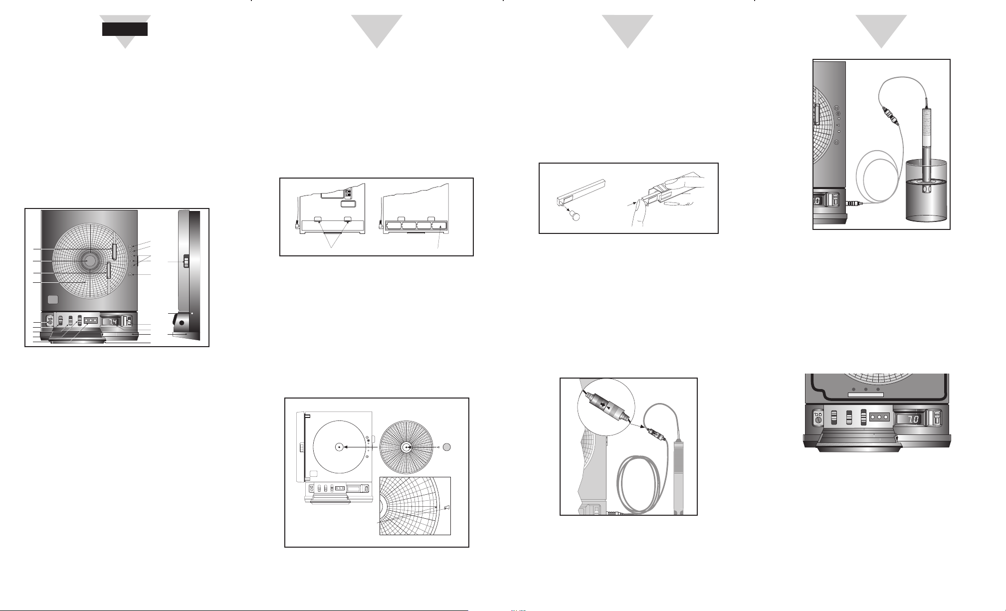
Parts of the CTpH
Figure 1. CTpH
Item Description
1 Chart Paper Knob (magnetic)
2 Light Bulbs
3 Pen Cap Posts
4 Time Set Arrow
5 Chart Paper (double sided)
6 ac Power Jack
7 Power Switch
8 Cal/Normal Mode Switch
9 1/7/32 Day Mode Switch
10 Alarm Display Buttons
11 LCD Display
12 Display Selection Switch
13 Pen Arm and Holder (2 each)
14 Latch Button
15 Control Panel Door Lock
16 Decorative Foot Cover
17 Control Panel Door
18 Light Bulb Push Button
HIGH SET LOW
1
7
32
Normal
Cal
0
I
CHART TYPE
PWR
ALARM
1
6
13
5
13
15
7
8
10
9
2
2
3
4
14
12
11
16 16
17
18
pH
°C
T
E
M
P
E
R
A
T
U
R
E
P
H
R
E
C
O
R
C
E
R
Figure 6. Using the 6 ft Remote Probe Cable
Calibrating pH Readings
1. Turn unit on and place probe in 7.00 buffer
solution.
2. Turn Cal. switch on Cal, Open door and
adjust Cal pot till display reads 7.00 on pH.
3. Place probe in 4.00 buffer and display should
read 4.00, if not adjust Slope pot.
4. Then close door and put Cal. switch on
Normal.
Figure 7. Calibration Adjustment Location
Probe
Remote
Probe
Cable
T
E
M
P
E
R
A
T
U
R
E
pH
°C
Buffer
Solution
Installing the Pens
1. Turn the recorder over (so it is front face up)
and open the main door.
2. Remove the pen caps and place on the posts
near the light bulbs. Install the pens as
shown in Figure 4. The green pen goes in the
pH pen arm and the red pen goes in the
temperature pen arm.
Figure 4. How to Install the Pens
Installing the Sensor
1. Place the handle part of the sensor into the
sensor clip on the side of the recorder.
2. Install the connector into the sensor socket.
Make sure the sensor cable is untwisted.
Refer to Figure 5.
3. To use the sensor in a remote location,
connect the 6 ft. remote sensor cable as
shown in Figure 5
Figure 5
pH
C
T
E
M
P
E
R
A
T
U
R
E
Installing the Batteries
1. Place the recorder on a soft surface front face
down.
2. Insert the 4 “D” size batteries in the battery
compartment as shown in Figure 2.
Batteries provide power if the ac adaptor is
not used. Otherwise, they provide power
backup in case of ac power failure. (NOTE:
the chart light bulbs function only when the
ac adaptor is used).
Figure 2. Battery Placement
Installing the Chart Paper
There are 20 charts of 3 different styles - 1 day/°C,
7 day/°C, and 32 day/°C. Choose the appropriate
chart paper and switch setting (1, 7 or 32
depending on paper used) for your application.
Turn the recorder over (so that it is front face up)
and open the main door. Install the paper as
shown in Figure 3. Remove the chart paper knob
(item #2), line up the current time line on the chart
paper with the arrow on the chart base and then
replace the knob to hold the chart paper in place.
Figure 3. Chart Paper Installation
RH
HIGH SET LOW
1
7
32
°F
°F
°C
°C
0
CHART TYPE
PWR
ALARM
1
7 PM
8
P
M
9
PM
6
P
M
5
P
NOTE: ROTATE CHART PAPER
UNTIL PRESENT TIME
LINES UP WITH ARROW.
H
35
1
2
To Open Battery Orientation
+–+–+–+–
Bench Top Set-Up
HIGH SET LOW
1
7
32
Normal
Cal
0
I
CHART TYPE
PWR
ALARM
pH
°C
SLOPE CAL TEMP
START HERE
2
3
4
 Loading...