

Page 1
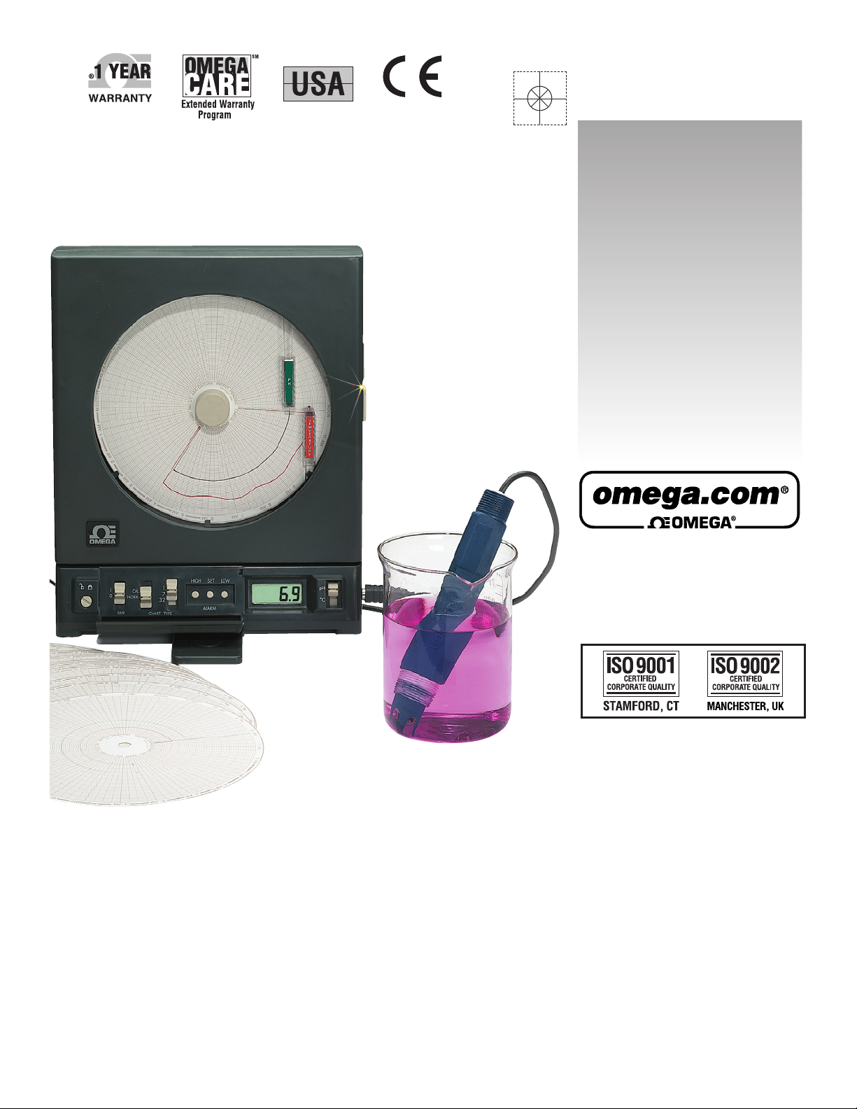
CTpH-110V-G-AL,
CTpH-220V-G-AL,
High Performance
Microprocessor-Based pH
and Temperature Recorder
MADE IN
220 V
Model Only
Electronics
Only
omega.com
e-mail: [email protected]
For latest product manuals:
omegamanual.info
Shop online at
User’s Guide
Page 2

This device is marked with the international hazard symbol. It is important to read the Setup Guide before
installing or commissioning this device as it contains important information relating to safety and EMC.
Servicing North America:
U.S.A.: One Omega Drive, P.O. Box 4047
ISO 9001 Certified Stamford, CT 06907-0047
TEL: (203) 359-1660 FAX: (203) 359-7700
e-mail: [email protected]
Canada: 976 Bergar
Laval (Quebec) H7L 5A1, Canada
TEL: (514) 856-6928 FAX: (514) 856-6886
e-mail: [email protected]
For immediate technical or application assistance:
U.S.A. and Canada: Sales Service: 1-800-826-6342 / 1-800-TC-OMEGA
®
Customer Service: 1-800-622-2378 / 1-800-622-BEST
®
Engineering Service: 1-800-872-9436 / 1-800-USA-WHEN
®
Mexico: En Espan˜ ol: (001) 203-359-7803 e-mail: [email protected]
FAX: (001) 203-359-7807 [email protected]
Servicing Europe:
Benelux: Postbus 8034, 1180 LA Amstelveen, The Netherlands
TEL: +31 (0)20 3472121 FAX: +31 (0)20 6434643
Toll Free in Benelux: 0800 0993344
e-mail: [email protected]
Czech Republic: Frystatska 184, 733 01 Karviná, Czech Republic
France: 11, rue Jacques Cartier, 78280 Guyancourt, France
TEL: +33 (0)1 61 37 2900 FAX: +33 (0)1 30 57 5427
Toll Free in France: 0800 466 342
e-mail: [email protected]
Germany/Austria: Daimlerstrasse 26, D-75392 Deckenpfronn, Germany
TEL: +49 (0)7056 9398-0 FAX: +49 (0)7056 9398-29
Toll Free in Germany: 0800 639 7678
e-mail: [email protected]
United Kingdom: One Omega Drive, River Bend Technology Centre
ISO 9002 Certified Northbank, Irlam, Manchester
M44 5BD United Kingdom
TEL: +44 (0)161 777 6611 FAX: +44 (0)161 777 6622
Toll Free in United Kingdom: 0800-488-488
e-mail: [email protected]
OMEGAnet®Online Service Internet e-mail
omega.com [email protected]
It is the policy of OMEGA Engineering, Inc. to comply with all worldwide safety and EMC/EMI
regulations that apply. OMEGA is constantly pursuing certification of its products to the European New
Approach Directives. OMEGA will add the CE mark to every appropriate device upon certification.
The information contained in this document is believed to be correct, but OMEGA accepts no liability for any
errors it contains, and reserves the right to alter specifications without notice.
WARNING: These products are not designed for use in, and should not be used for, human applications.
Page 3

The following models are available:
CTpH-110V-G-AL 110Vac, with Alarms and Relay Contacts
CTpH-220V-G-AL 220Vac, with Alarms and Relay Contacts
The following consumable items are available:
PENS
CT486-PS Pen Set, Red and Green, package of 1 each
CT486-PS-6 Pen Set, Red and Green, package of 6 each
STANDARD CHART PAPER (double-sided - available as single package of 100 or 6 packages of 100 charts)
CTpH-CDC
100
Charts, 1 Day, °C CTpH-CDC-6
600
Charts, 1 Day, °C
CTpH-CWC
100
Charts, 7 Day, °C CTpH-CWC-6
600
Charts, 7 Day, °C
CTpH-CMC
100
Charts, 32 Day, °C CTpH-CMC-6
600
Charts, 32 Day, °C
The following spare parts are available:
CT485B-WALLKIT Anchors, Screws, Inserts and Template
CT485-CABLE-6G 6 Ft. (2 meter) Remote Probe Cable, Gray
CT485-AC-110-G 110Vac Adaptor, 9Vdc output, Black
CT485-ADAP-E-G 220Vac Adaptor, 9Vdc output, Black, European Plug
CT485-ADAP-UK-G 220Vac Adaptor, 9Vdc output, Black, United Kingdom Plug
CT485B-MAG Magnetic Chart Knob, Tan
CT485B-BULB Light Bulb Assembly, package of 10
CTpH-Probe Replacement pH Probe
CTpH-CAL-KIT Calibration Kit
CTpH-CAL-LABEL Calibration Lockout Cover Labels (Sheet of 10)
CT485-CAL-LOCK Calibration Lockout Kit
PHA-4 Buffer solution, pH 4.01
PHA-7 Buffer solution, pH 7.00
PHA-10 Buffer solution, pH 10.00
The following accessories are available:
CTpH-BNC Analog BNC Input Adaptor (Cable), Gray
PART NUMBER DESCRIPTION
PART NUMBER DESCRIPTION
PART NUMBER DESCRIPTION
PART NUMBER DESCRIPTION
Page 4

Notes
Page 5

i
Page
Chapter 1 Introduction ....................................................................... 1-1
1.1 Parts of the Recorder - Front and Side Views .................................. 1-2
1.2 Parts of the Recorder - Rear View ...................................................... 1-4
Chapter 2 Setting Up the Recorder ..................................................... 2-1
2.1 Placing the Recorder on the Bench Top ............................................ 2-1
2.2 Mounting the Recorder on the Wall .................................................. 2-3
2.3 Using Batteries ...................................................................................... 2-4
2.3.1 Installing Batteries ................................................................... 2-4
2.3.2 Connecting ac Power .............................................................. 2-5
2.4 Installing the Chart Paper ................................................................... 2-6
2.5 Installing and Removing Pens ........................................................... 2-8
2.5.1 Installing the Pens ................................................................... 2-8
2.5.2 Removing the Pens ................................................................ 2-10
2.6 Installing the pH/Temperature Probe ............................................ 2-11
2.6.1 Using the Sensor .................................................................... 2-11
2.6.2 Using the Remote Sensor Cable .......................................... 2-12
Chapter 3 Powering Up the Recorder ................................................. 3-1
3.1 Turning on the Recorder ..................................................................... 3-1
3.2 Recording the Code Numbers ............................................................ 3-1
3.3 Final Display Mode .............................................................................. 3-2
Chapter 4 Alarm Operation ............................................................... 4-1
4.1 Alarm Description ............................................................................... 4-1
4.2 Checking Alarm Limits ....................................................................... 4-1
4.3 Unlocking/Locking the Control Panel Door ................................... 4-2
4.3.1 Unlocking the Control Panel Door ....................................... 4-2
4.3.2 Locking the Control Panel Door ........................................... 4-2
4.4 Setting/Changing Alarm Limits ........................................................ 4-3
4.5 Turning the Alarm Off ......................................................................... 4-4
4.6 Disabling the Alarm ............................................................................ 4-5
Chapter 5 Calibrating the Recorder .................................................... 5-1
5.1 Factory Calibration Information ........................................................ 5-1
5.2 Changing Calibration Codes .............................................................. 5-1
5.3 Calibrating pH Readings .................................................................... 5-3
Chapter 6 Using the Cal-Lock Kit ........................................................ 6-1
Chapter 7 Using the BNC Input Adapter (Optional) ............................. 7-1
High Performance Microprocessor-Based
pH/Temperature Recorder with Remote Sensor
TABLE OF
CONTENTS
Page 6

Chapter 8 Maintaining the Recorder .................................................. 8-1
8.1 General Considerations ....................................................................... 8-1
8.2 Light Bulb and Push Button Information ......................................... 8-2
8.3 Case Care................................................................................................ 8-3
8.4 Storage of Chart Paper ........................................................................ 8-3
8.5 Power Failure Mode (Chart Paper Indication) ................................ 8-3
Chapter 9 Troubleshooting the Recorder ............................................ 9-1
Chapter 10 Technical Details ............................................................ 10-1
10.1 Probe and Measurement ................................................................... 10-1
10.2 Pen Arm Drive .................................................................................... 10-1
10.3 Chart Paper Drive Mechanism ......................................................... 10-2
10.4 Power Supply Supervision ............................................................... 10-2
Chapter 11 Specifications ................................................................ 11-1
Index ....................................................................................................... I
High Performance Microprocessor-Based
pH/Temperature Recorder with Remote Sensor
ii
TABLE OF
CONTENTS
Page 7

Introduction
1-1
1
This Electronic pH and Temperature Chart Recorder with Remote Sensor is an
advanced microcomputer controlled measuring and recording instrument.
This Recorder is a class III Equipment, and the ac Power Adapter provides
double insulation as means of protection against electric shock.
The recorder affords rapid and precise response, memory and display of peak
readings, remote sensing, recording flexibility and simplicity of operation. This
compact, portable instrument offers advanced features previously unavailable in
its price range.
Features include:
• Continuous Update of Fluid pH and Temperature
• Rapid Response to Changes in Fluid pH and Temperature
• Remote Probe
• Digital Plots in 1.0 °C or 0.1pH Increments
• Memory and Display of Peak Readings
• 1, 7 or 32 Day Charts
• Battery or ac Power Operation With Automatic Battery Power Backup
• Chart Indication for ac Power Failure/ac Power Return
• Audible Alarm with Relay Contact
• Low Battery Indicator
• Portable
• Wall Mount or Benchtop Mount
• Optional Analog Voltage Input Adapter to record an external -296 to 414mV
dc signal through a standard BNC connector
• Chart Lighting and back-lit LCD display with use of ac adapter
• Control Panel Lock
• Decorative Foot Cover for wall mounting
These features provide precise documentation, flexibility in application and ease
of use, all made possible through the incorporation of advanced electronics.
Page 8
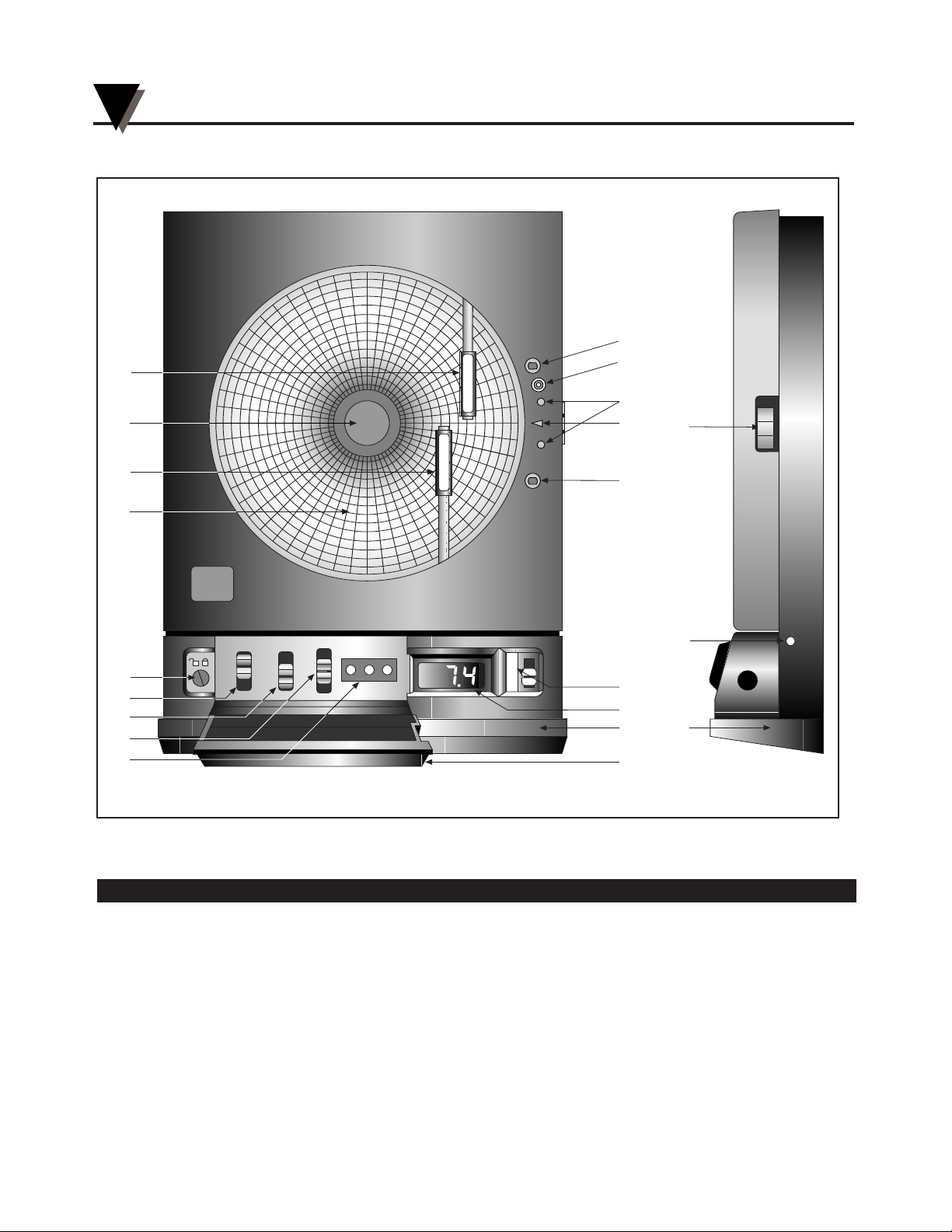
1.1 Parts of the Recorder - Front and Side Views
Figure 1-1. Front and Side Views of the Recorder
Item Description Function
1 Chart Paper Knob (magnetic) Holds chart paper in place.
2 Light Bulbs Lights up the paper in a dark room. Note that the bulbs function only
when the recorder is powered by the 9Vdc adapter.
3 Pen Cap Posts Holds the loose pen caps.
4 Time Set Arrow Helps align the time on the new chart paper with the actual time.
5 Chart Paper (double sided) Charts are available for 1, 7, and 32 day recording times. See the
inside back cover for a detailed list of paper available.
HIGH SET LOW
1
7
32
Normal
Cal
0
I
CHART TYPE
PWR
ALARM
1
6
13
5
13
15
7
8
10
9
2
2
3
4
14
12
11
16
16
17
18
pH
°C
T
E
M
P
E
R
A
T
U
R
E
P
H
R
E
C
O
R
C
E
R
Introduction
1
1-2
FRONT VIEW SIDE VIEW
Page 9

Item Description Function
6 ac Power Jack Allows the unit to be powered from ac power using the adapter
(110Vac or 220 Vac stepped down to 9Vdc) supplied.
7 Power Switch Turns unit ON (|) or OFF (O).
8 Cal/Normal Mode Switch Selects Cal mode for pH probe calibration, using adjustments
on chart base, or normal operation mode.
9 1/7/32 Day Mode Switch Selects chart type: 1, 7, or 32 day operation.
10 Alarm Display Buttons These buttons are accessible behind the control panel door.
(HIGH, SET, LOW) High and Low buttons:
1. Selects and changes calibration codes.
2. Chooses the high/low alarm limit (for either °C or pH).
3. Selects and changes the alarm limits.
4. Checks alarm limits in operating mode.
5. Low button only: when pressed during power up, disables the
alarm function.
Set button:
1. Activates calibration mode when pressed during power up.
2. Enters calibration codes in memory.
3. Activates alarm limits.
4. Enters alarm limits in memory.
5. Disables the sounding of the alarm (and activation of the relay)
for 10 seconds.
11 LCD Display Displays temperature and pH values (depending on the setting of
Display Selection Switch). (Refer also to item #18)
12 Display Selection Switch Allows the user to select display pH or fluid temperature in °C .
(Refer also to item #11).
13 Pen Arm and Holder (2 each) Holds and moves the pH and temperature pens.
14 Latch Button Releases and secures the recorder’s door.
15 Control Panel Door Lock Locks or unlocks the control panel door.
16 Decorative Foot Cover Stays in place for wall-mounting the recorder. Removed for upright
bench-top use.
17 Control Panel Door Covers the alarm display buttons (High, Set, and Low), power switch,
1/7/32 day mode switch, and Cal/Normal mode switch.
18 Light Bulb Push Button Turns the light bulbs and LCD back-light on and off with
ac adapter only.
Introduction
1
1-3
Page 10
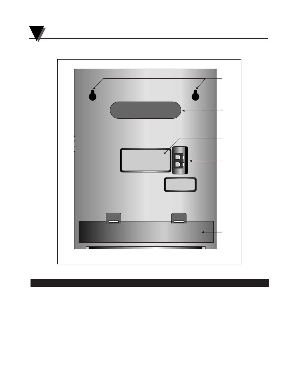
1.2 Parts of the Recorder - Rear View
Figure 1-2. Rear View
Item Description Function
19 “Keyhole” Slot Mounting Holes Allows the recorder to be mounted on the wall.
20 Carrying Slot Allows the user to carry the recorder conveniently.
21 Product Label Product information label.
22 Alarm/Relay Contacts Allows the user to hook up an external, dry contact alarm to the
recorder.
23 Battery Compartment Holds 4 “D” size batteries which provide power if the ac adapter is not
used, or with adapter, provide power backup in case of ac power
failure.
23
19
20
22
Foot Cover Removed
21
Introduction
1
1-4
Page 11

Introduction
1
1-5
Page 12

Introduction
1
1-6
Page 13
Setting Up the Recorder
2-1
Now that you have learned about the different parts of the recorder, you can set
it up.
Determine whether you want the recorder wall mounted or sitting on a bench
top.
2.1 Placing the Recorder on the Bench Top
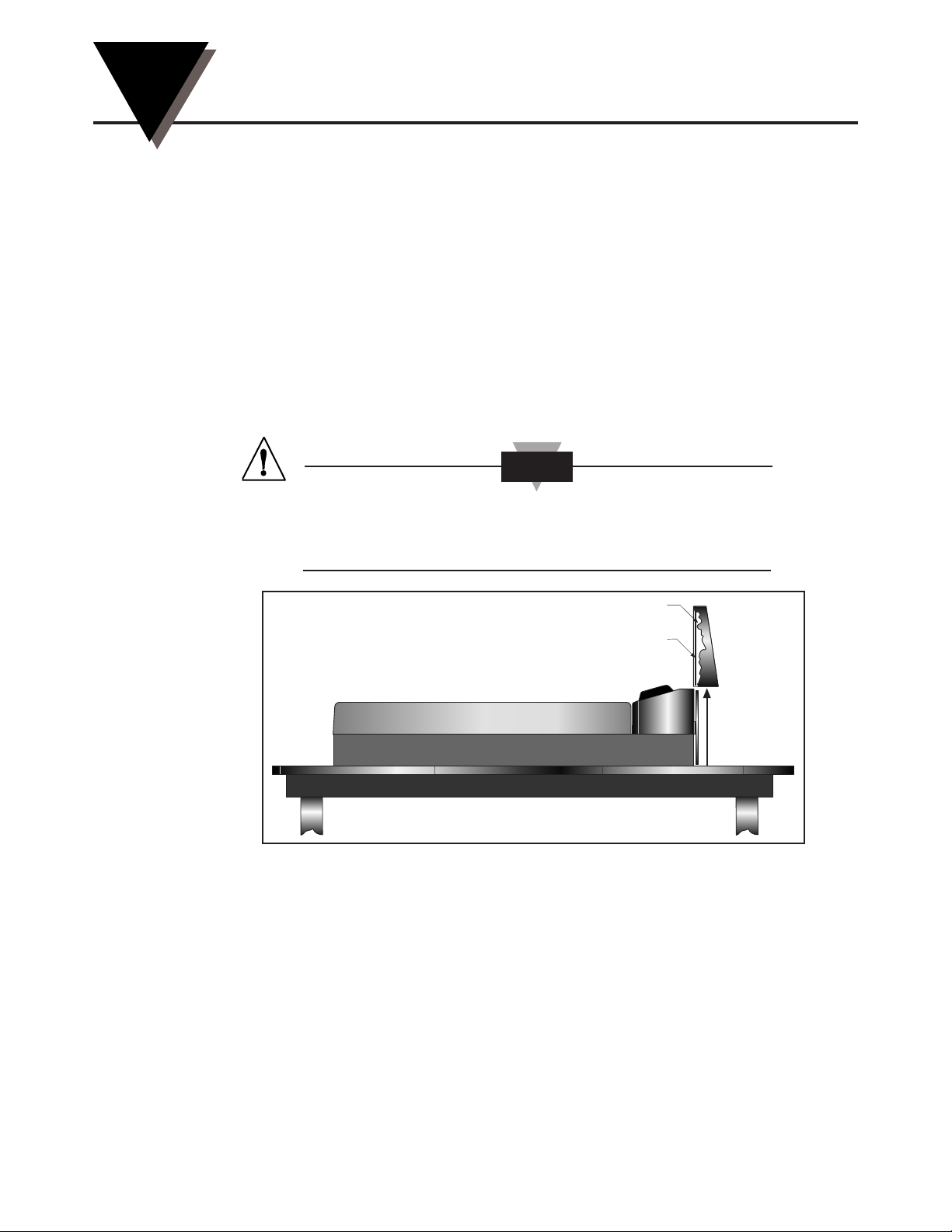
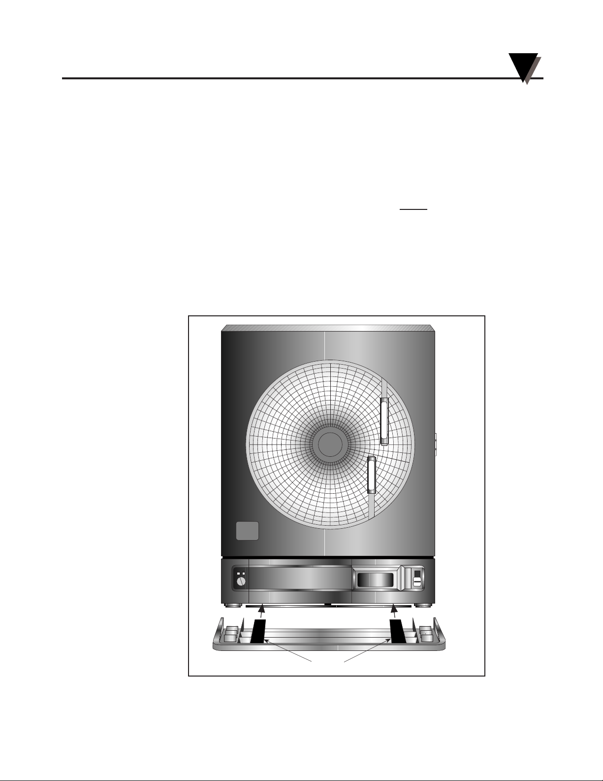
Figure 2-1 shows the removal of the decorative foot cover.
1. Place the recorder on its back (so it is face up).
2. Remove the clip-on foot cover by lifting up on the cover and releasing it from
the stabilizing arm at the bottom of the recorder. This exposes the rubber feet
and stabilizing arm. The rubber feet protect the bench top surface.
DO NOT ATTEMPT TO SET THE RECORDER UPRIGHT ON
THE BENCH WHEN THE CLIP-ON FOOT COVER IS IN
PLACE. THE RECORDER WILL TOPPLE OVER.
Figure 2-1. Foot Cover Removal
Clip
Cutaway View
CAUTION
2
Page 14
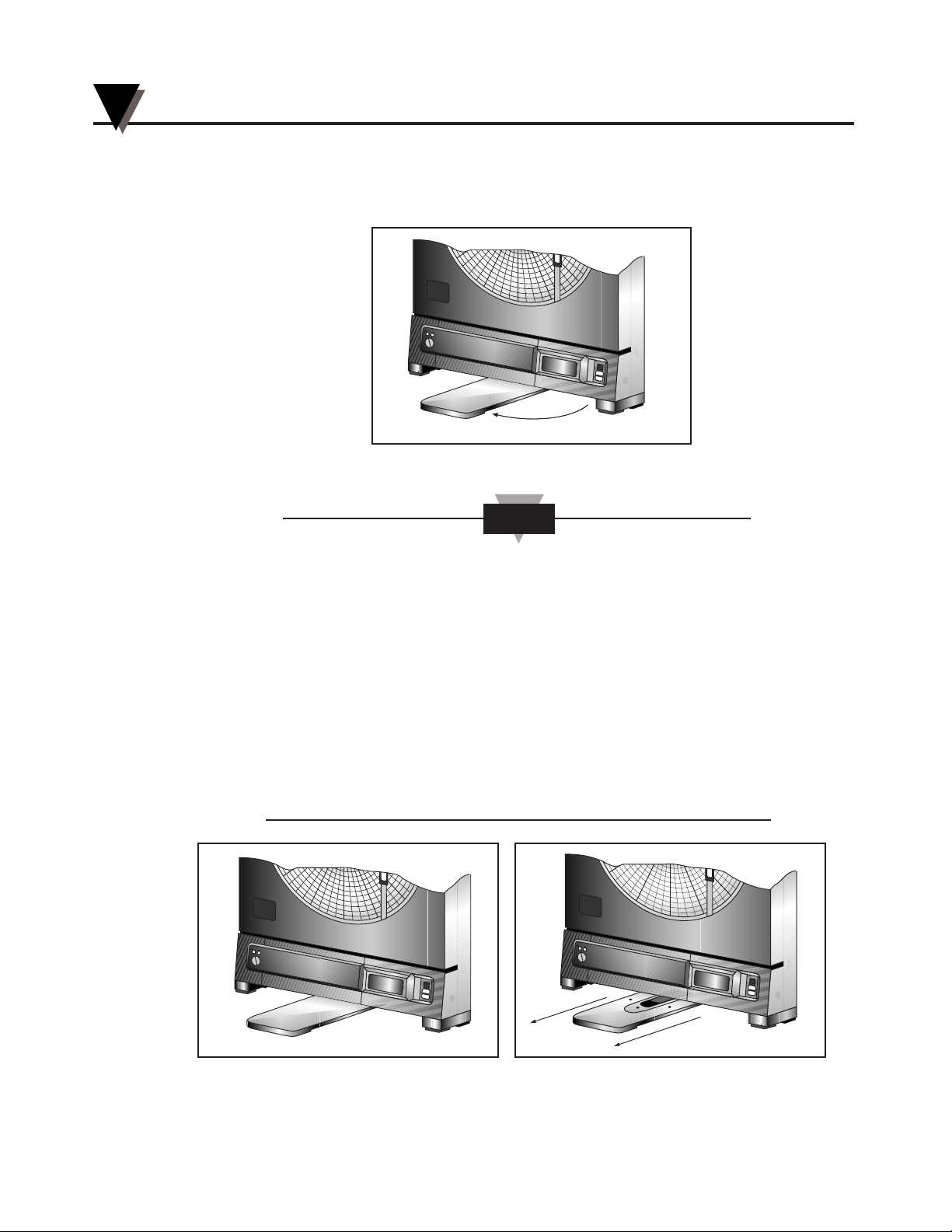
3. Swing out the stabilizing arm and extend it towards you. Figure 2-2 shows how
to swing out the stabilizing arm. Make sure the slot in the stabilizing arm
extends out the rear of the recorder.
Figure 2-2. Swiveling Stabilizing Arm
When the recorder is in normal operating position (the door is
closed and the control panel door is closed), the stabilizing arm
should be pushed to middle position (the bumps on the arm will
click in place under the recorder). Refer to Figure 2-3a.
Before opening the door, pull the stabilizing arm out to its full
extension position to provide full stability. Refer to Figure 2-3b.
After closing the door, return the arm to its middle position. Refer
to Figure 2-3a.
Note that the arm extends towards the front or rear of the case. If
the unit is placed on a bench top snug against the wall, extend the
stabilizing arm fully to the front of the unit. Refer to Figure 2-3b.
Figure 2-3a. Stabilizing Arm use Figure 2-3b. Stabilizing Arm in Extended
for Bench Top Use (normal position) Position (position when you open door)
H
U
M
I
D
I
T
Y
pH
°C
H
U
M
I
D
I
T
Y
pH
°C
CAUTION
Swing
H
U
M
I
D
I
T
Y
pH
°C
Setting Up the Recorder
2-2
2
Page 15
2.2 Mounting the Recorder on the Wall
To mount the recorder on the wall, first locate the wall mounting holes using the
template provided in the wall mounting kit. Leave the decorative foot cover
(Figure 1-1, item #16) in place*. After drilling the holes, insert the wall anchors
and put in the screws, leaving
1
⁄8 inch (3 mm) between the screw heads and the
wall. Hang the recorder by positioning the two (2) “keyholes” in the rear cover
over the screw heads.
The ac adaptor has a 6 foot (2 meter) cable.
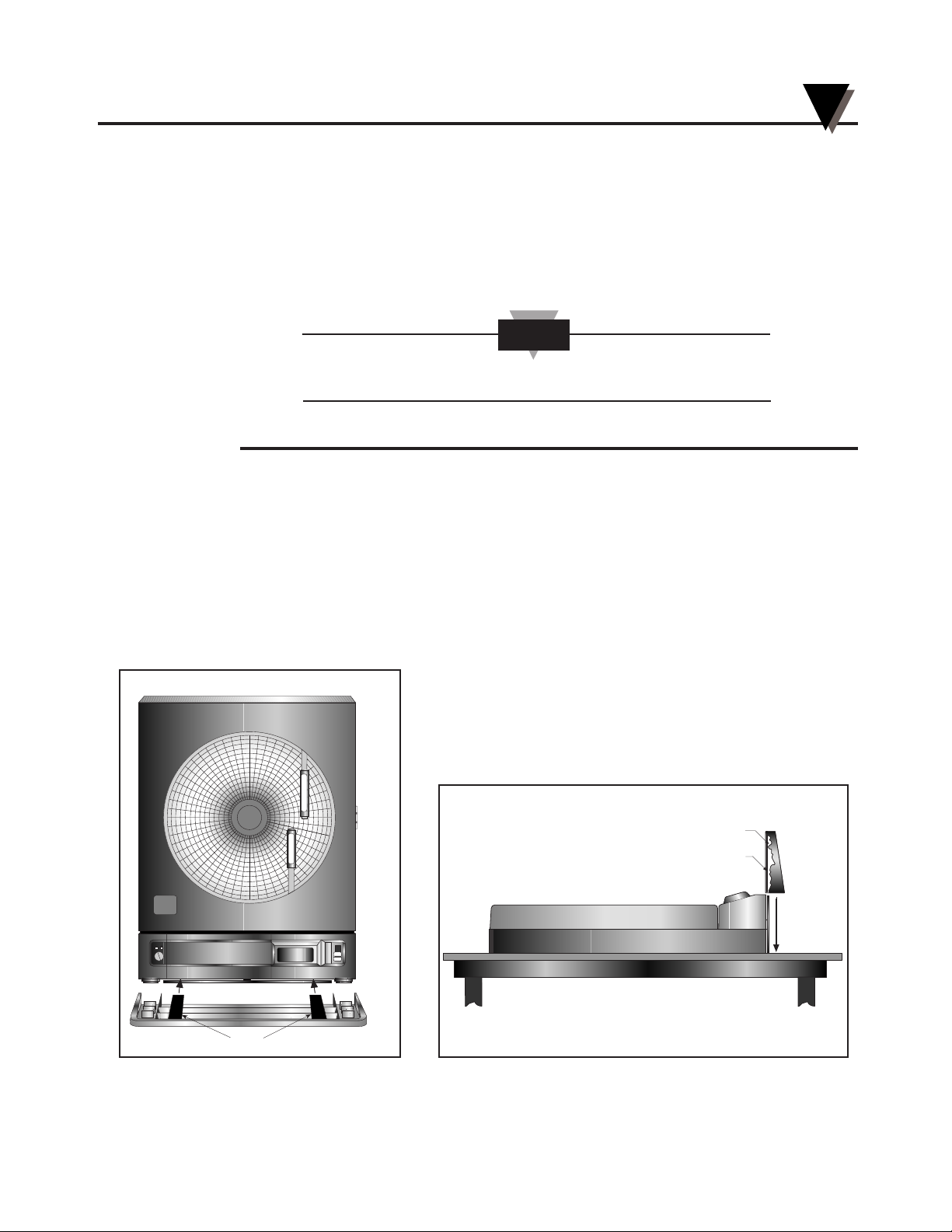
* If the decorative foot cover is not in place, go through the following steps to
reinstall the cover (if desired):
1. Place the recorder on the table (so it is front face up).
2. Roughly position the foot cover so the clips are in line with the stabilizing
arm. Gently “stretch” the clips out and position over the arm as shown in
Figure 2-4a.
3. Once the clips are in place, gently slide down until the foot cover is even
with the front of the recorder as shown in Figure 2-4b.
Figure 2-4a. Installing the Foot Cover Figure 2-4b. Installing the Foot Cover (Side View)
(Top View)
Clip
Cutaway View
Clips
pH
C
P
H
R
E
C
O
R
D
E
R
T
E
M
P
E
R
A
T
U
R
E
CAUTION
Setting Up the Recorder
2
2-3
Page 16
2.3 Using Batteries
The recorder operates on either four “D” size batteries or on ac power. 110Vac
and 220Vac adaptors are available.
In the event of ac power failure, the unit will switch over to
battery power automatically.
Keep a fresh set of batteries in the unit in case of power
outage, when it can be especially important to have a record
of pH and fluid temperature.
2.3.1 Installing Batteries
You may power the recorder with four “D” size batteries. For adequate
performance and battery life, use alkaline batteries. The recorder operates full
time on battery power alone for up to one month when using fresh alkaline
batteries. When replacing batteries, we recommend that you use Duracell
MN1300 “D” size batteries for long life and for best performance at low
temperatures.
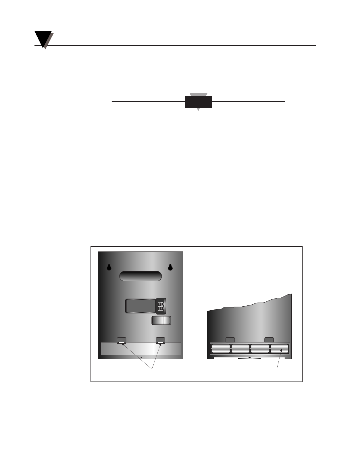
To install the batteries (refer to Figure 2-5):
Figure 2-5. Battery Compartment and Battery Orientation
To Open
Battery Orientation
+–+–+–+–
Bench Top Set-Up
NOTE
Setting Up the Recorder
2
2-4
Page 17
1. Open the control panel door.
2. Turn the power switch to “O” position.
3. Place the recorder on a soft surface front face down. Locate the battery
compartment at the bottom.
4. Open the battery compartment door by pressing down firmly on the tabs
located along the top edge.
5. Remove the battery door.
6. Install the batteries, oriented as shown in Figure 2-5, in the battery
compartment.
7. To replace the battery door, first place the bottom edge of the door into the
positioning slots in the compartment.
8. Push down on the door to snap the tabs in place.
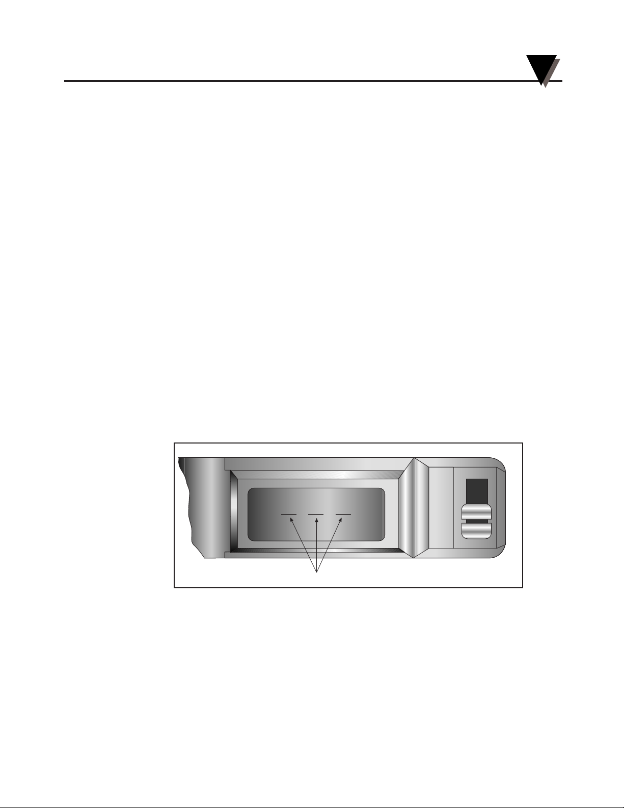
The recorder continuously monitors the battery voltage. A “LO BAT” indication
in the upper left-hand corner of the main LCD (refer to Figure 2-6) indicates
that only one to two weeks of reliable battery operation remain, and that the
batteries need replacing within this time frame. Also, if the unit is operating
under battery power and the battery voltage is too low to permit reliable
operation, the system shuts down and displays “---” in the LCD. The system
may be restarted by changing the batteries or by the re-initiation of ac power. If
ac power fails, the circuitry will attempt to automatically switch to battery
backup. If viable battery power is available, the system will operate on battery
power until the batteries fail or ac power returns. When ac power returns, the
recorder will automatically reset itself (refer to Section 8.5).
Figure 2-6. Battery Warnings
2.3.2 Connecting ac Power
The recorder can be ac powered using the 9Vdc, 1Amp ac adaptor supplied. The
ac power jack is located on the right side of the unit (refer to Figure 1-1, item #6.).
Make sure the power switch on the control panel (refer to Figure 1-1, item #7) is
in the “O” position when plugging in the ac adaptor. The adaptor cable is 6 feet
(2 meters) long.
pH
°C
System Shut-Down
LO BAT
Setting Up the Recorder
2
2-5
Page 18
2.4 Installing the Chart Paper
The recorder accepts three different types of chart paper. Charts are available for
1, 7 and 32 day recording times. Although chart paper replacing is very simple,
you must take care to set the appropriate front panel switches to match the paper
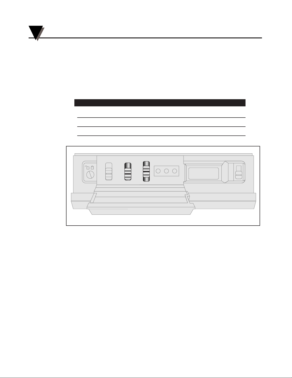
being used. Set the chart type and Cal/Normal switches (refer to Figure 2-7) to
the following positions for these three (3) modes of operation.
Chart Type Switch (Days) Paper Type
1 1-day, pH and Celsius paper
7 7-day, pH and Celsius paper
32 32-day, pH and Celsius paper
Figure 2-7. Chart Switches
pH
°C
HIGH SET LOW
1
7
32
NORMAL
CAL
0
I
CHART TYPE
PWR
ALARM
Setting Up the Recorder
2
2-6
Page 19
To change the chart paper:
1a. T
able Mounted Recorder:
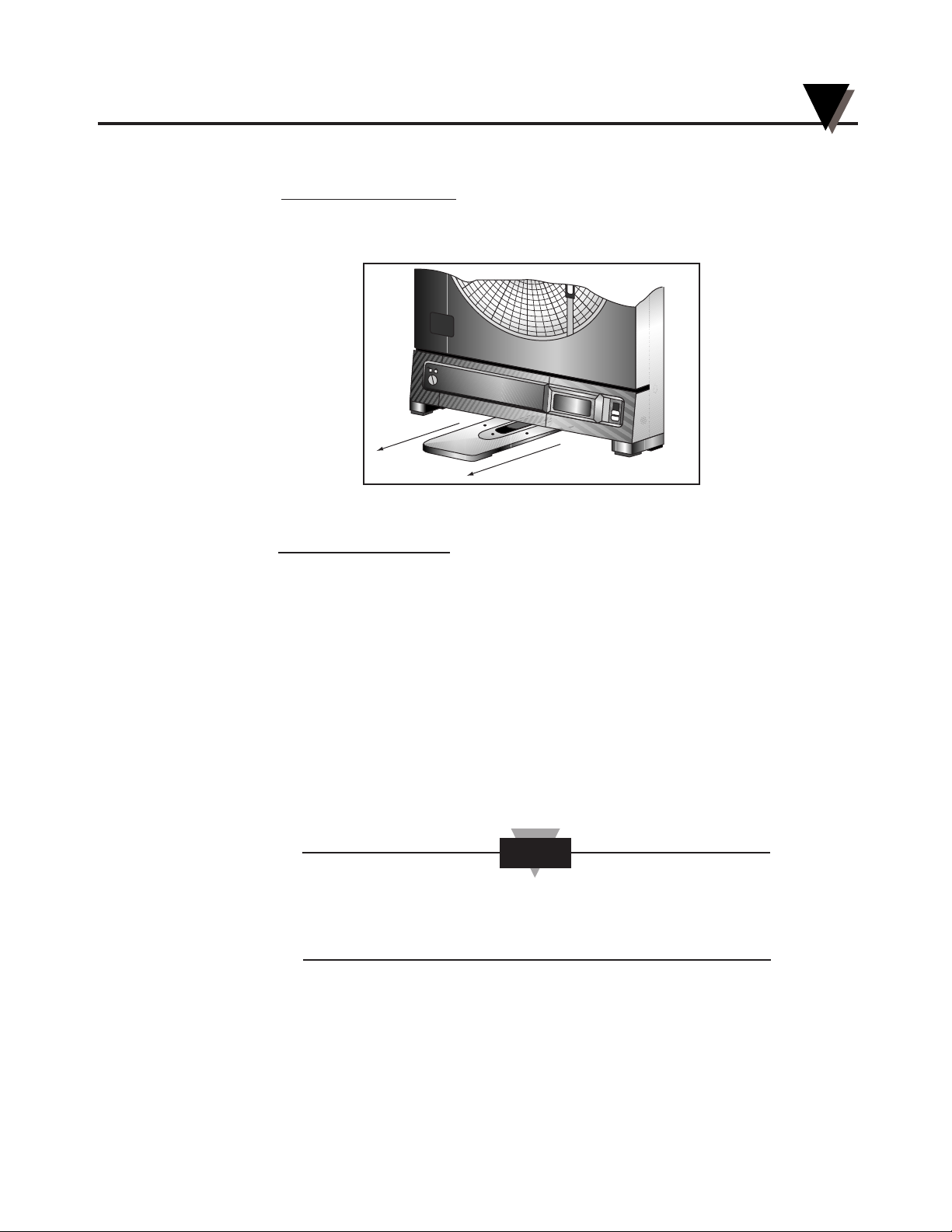
To balance the recorder, fully extend the stabilizing arm at the bottom of the
recorder. Refer to Figure 2-8. Continue to Step 2.
Figure 2-8. Stabilizing Arm Fully Extended
1b. W
all Mounted Recorder
:
You can also leave the recorder on the wall if it is easily accessible.
2. Open the door and hold it open with left hand.
3. Remove the magnetic chart paper knob (Figure 2-9, item #2) and used chart
paper.
4. Place the new chart paper (Figure 2-9, item #1) on the spindle and rotate it
until the current time on the chart paper is aligned with the time arrow on the
chart base of the recorder. See Figure 2-9 detail.
5. When the chart paper is correctly oriented, replace the magnetic knob
(Figure 2-9, item #2), being careful not to alter the position of the chart paper.
6. Make sure that the “Chart Type” switch, located behind the control panel door,
is in the correct position relative to the chart paper used.
If the switch is in the wrong position, the chart paper will not
rotate at the correct speed and the indicated chart time will
not correspond to real time.
NOTE
H
U
M
I
D
I
T
Y
pH
°C
Setting Up the Recorder
2
2-7
Page 20
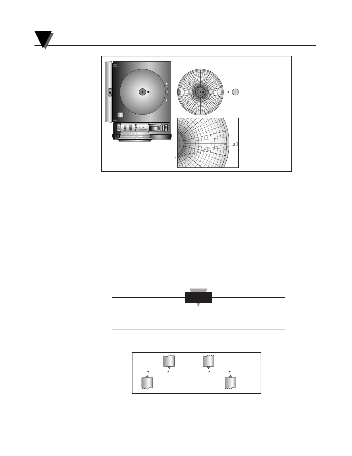
Figure 2-9. Changing Chart Paper and Setting the Time
2.5 Installing and Removing Pens
2.5.1 Installing the Pens
The recorder uses two different colored pens to record information. The green
(upper) pen records pH. The red (lower) pen records temperature. Pen life varies
with use and climate. Under normal operating conditions, pens last at least one
month. We recommend that you install a fresh set of pens after every month of
use.
To install pens:
1. Make sure the power switch on the front panel is in “O” position. The front
panel is located under the control panel door. The recorder door should be
closed.
The control panel door opens easily by gently gripping the
recessed area at the right side and slowly pulling down.
2. Examine the location of the pen arms through the window in the recorder door.
a. If the pen arms are offset as shown in Figure 2-10, continue to Step 3:
Figure 2-10. Offset Alignment of Pens (for ease of pen installation)
OR
Temperature
Pen
Temperature
Pen
pH Pen pH Pen
NOTE
HIGH SET LOW
1
7
32
Normal
Cal
0
CHART TYPE
PWR
ALARM
1
7 PM
8 PM
9
PM
6 PM
5
P
NOTE: ROTATE CHART PAPER
UNTIL PRESENT TIME
LINES UP WITH ARROW.
1
2
pH
°C
Setting Up the Recorder
2
2-8
7:00 PM
Page 21
b. If the pen arms are vertically aligned as shown in Figure 2-11, do the
following and then proceed to Step 3.
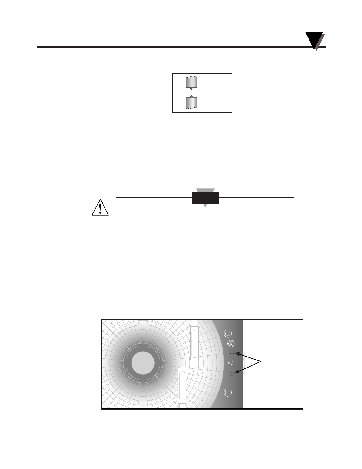
Figure 2-11. Vertical Alignment of Pens (pens can’t be inserted)
(The pen arms must be offset sufficiently to allow for clearance before insertion
or removal is attempted. The pens must be moved electrically.)
• Make sure the recorder door is closed and a piece of chart paper is
installed on the spindle on the chart base.
• Turn the unit back on by moving the power switch to “|” and wait for
the pens to be far enough apart to remove a used pen one at a time or
to insert a new pen one at a time.
DO NOT ATTEMPT TO OFFSET THE PENS
MANUALLY (BY HAND). THE DRIVE MECHANISM
COULD BE DAMAGED. DO NOT ATTEMPT TO
CHANGE THE PENS WHILE THEY ARE IN MOTION.
• Turn off the unit (PWR switch position in “O” position) to stop the pen
movement.
3. Open the recorder door by applying downward pressure on the latch button
(refer to Figure 1-1, item #14).
4. Remove the pens from the package and the cap from each pen.
We recommend that you put the pen caps on special posts located on the chart
base of the recorder near the light bulbs. Figure 2-12 shows the location of the
posts.
Figure 2-12. Post Location for Pen Caps
p
H
R
E
C
O
R
D
E
R
T
E
M
P
E
R
A
T
U
R
E
Pen Cap Posts
CAUTION
Temperature
Pen
pH Pen
Setting Up the Recorder
2
2-9
Page 22
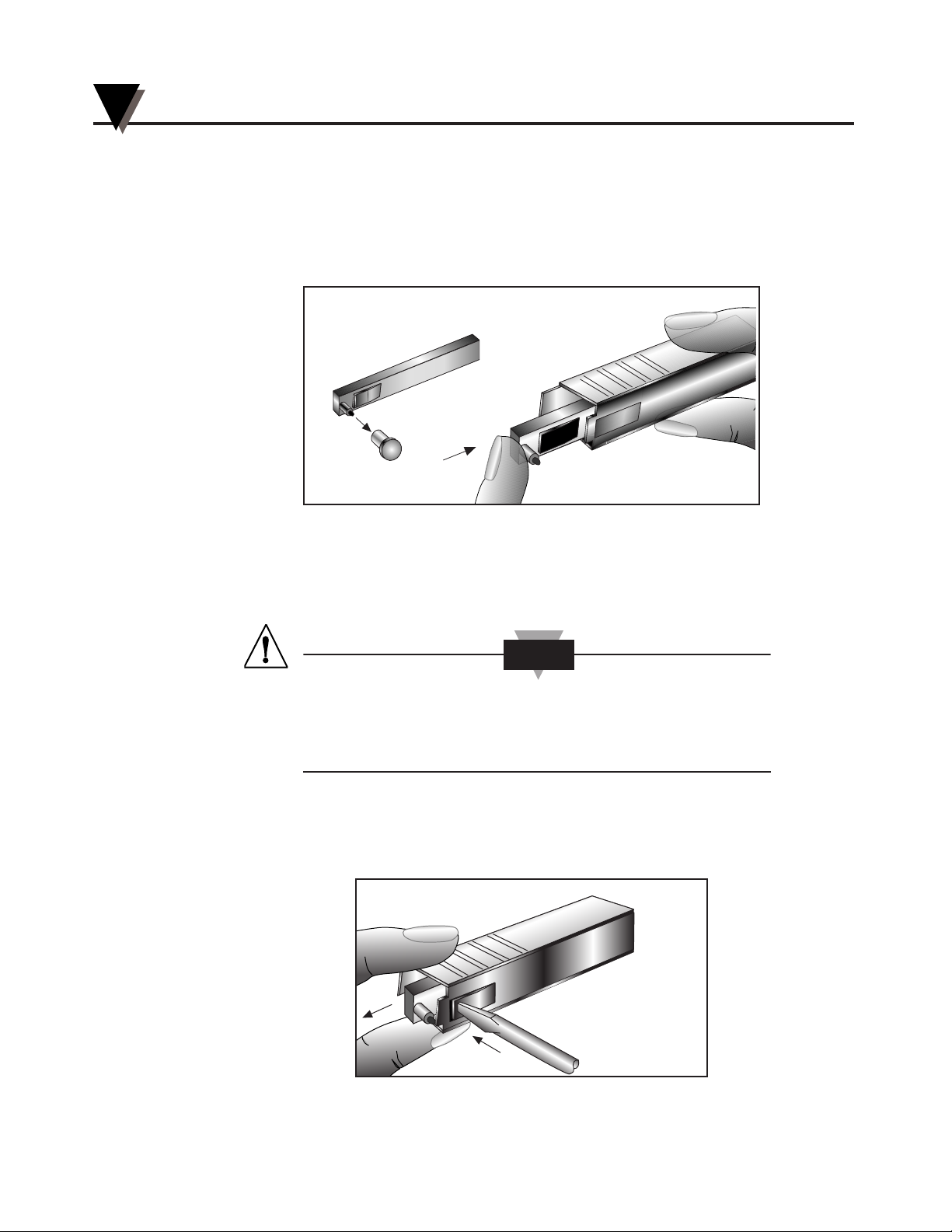
5. Insert the red pen fully into the lower (temperature) holder, and the green pen
fully into the upper (pH recorder) holder.
If you installed the pens correctly, you will hear a click as they position
themselves in the holders. Figure 2-13 shows how to insert the pens.
6. Close the recorder door.
Figure 2-13. Pen Installation
2.5.2 Removing the Pens
1. Check to see that the pens are offset as shown in Figure 2-10. Otherwise, you
can damage the arm and drive mechanism if you try to remove them.
DO NOT ATTEMPT TO OFFSET THE PENS MANUALLY (BY
HAND). THE DRIVE MECHANISM COULD BE DAMAGED.
DO NOT ATTEMPT TO CHANGE THE PENS WHILE THEY
ARE IN MOTION.
2. Perform Step 2b in Section 2.5.1 to offset the pens.
3. With a screwdriver in one hand, push on the rectangular area of the pen
shown in Figure 2-14. Using the other hand, release the pen from the spring
clip attached to the pen holder.
Figure 2-14. Pen Removal
CAUTION
Setting Up the Recorder
2
2-10
Page 23

4. At the same time, slide the pen out from the pen holder.
5. Install new pens following Section 2.5.1, Steps 3 through 6.
2.6 Installing the pH/Temperature Probe
The pH/temperature probe can either be directly attached to the recorder using
its own attached cable or be extended by using the remote probe cable.
2.6.1 Using the Probe
1. Install the connector into the socket at the side of the recorder. Make sure the
probe cable is untwisted.
Setting Up the Recorder
2
2-11
Page 24
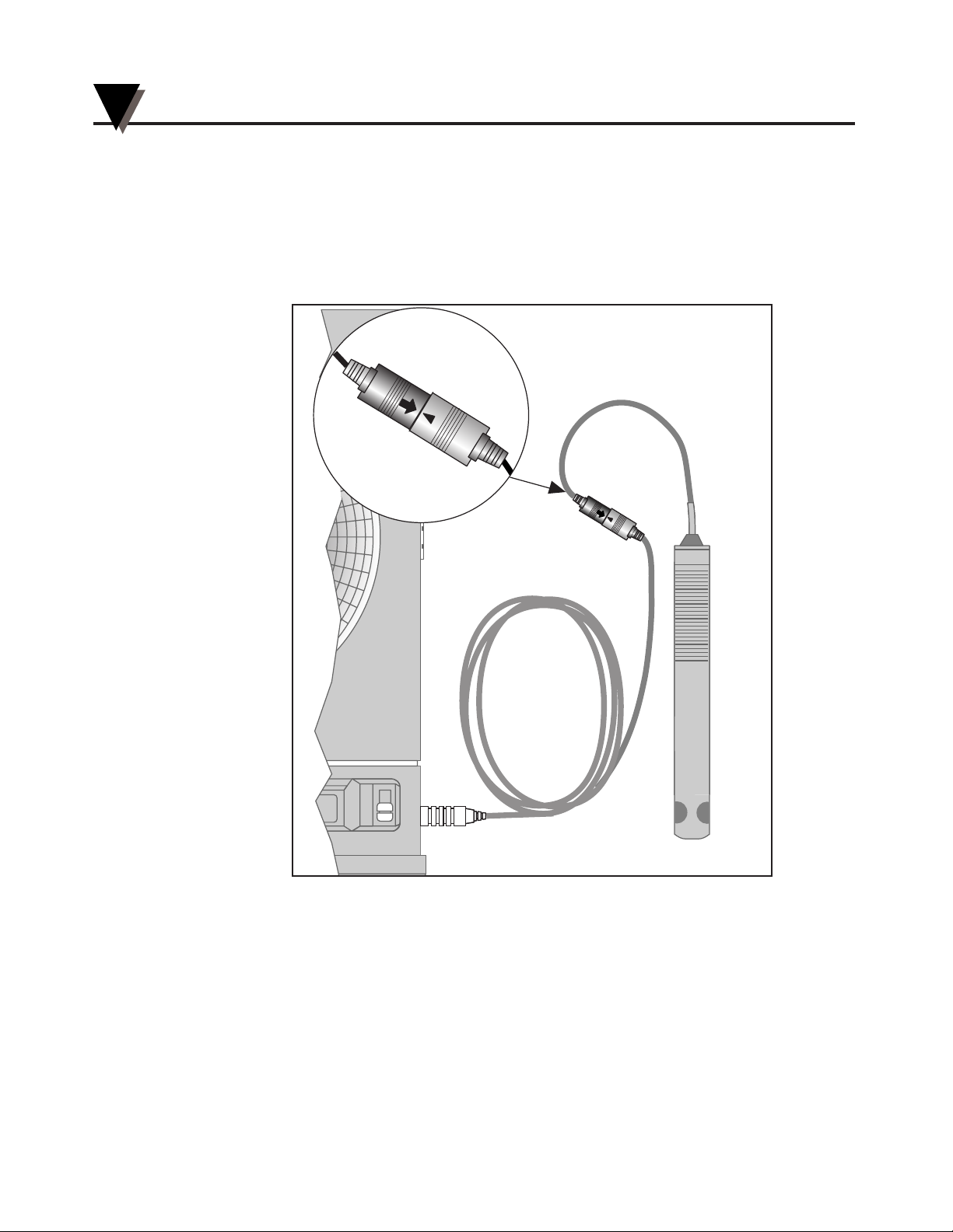
2.6.2 Using the Remote Probe Cable
1. Connect the end of the cable with the arrow to the cable on the probe. Line up
the two arrows as shown in Figure 2-15 before mating the two cables.
2. Connect the other end of the remote probe cable (without the arrow) to the
socket at the side of the recorder.
Figure 2-15. Using the Remote Probe Cable
pH
°C
T
E
M
P
E
R
A
T
U
R
E
Setting Up the Recorder
2
2-12
Page 25

Setting Up the Recorder
2
2-13
Page 26

Setting Up the Recorder
2
2-14
Page 27
Powering Up the Recorder
3-1
3
3.1 Turning on the Recorder
Open the control panel door by gently gripping the recessed area at the right
side of the door and slowly pulling down.
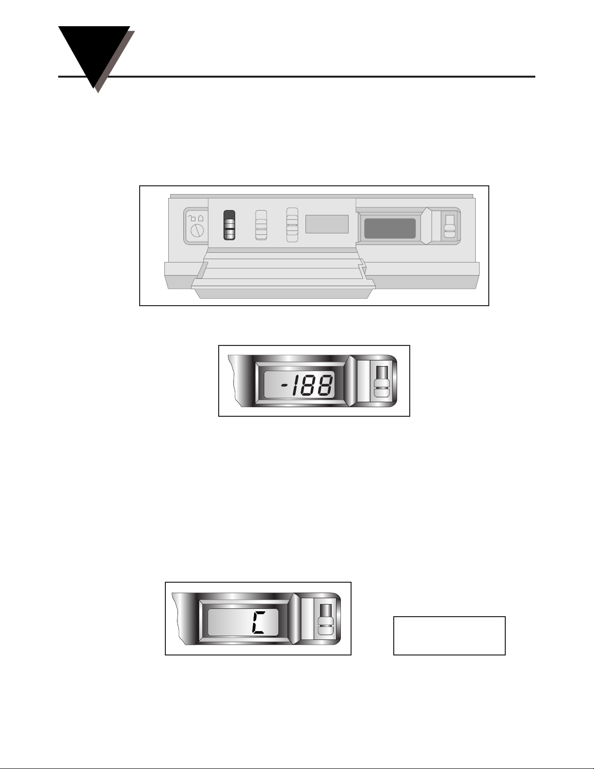
Turn the recorder on by moving the power switch located on the control panel to
the “|” position. Refer to Figure 3-1 for the location of the switch.
Figure 3-1. Power Switch
You then hear 1 beep and the LCD display shows the following:
Figure 3-2. First LCD Display
The displays in Section 3.2 come up quickly once you turn on the
recorder. Be prepared to write down the codes as you see them on the
recorder display. You can then compare the codes your recorder displayed
with the probe label as described below. After the two groups of codes
are displayed, the recorder continues with its sequence, and the pens
move. More details are provided in Sections 3.3 and 3.4.
3.2 Recording the Code Numbers
A two-character temperature code made up of numbers and/or letters 0, 1, 2,
3, ... , 8, 9, a, b, and c appears. An example is shown in Figure 3-3; the numbers
will vary:
Figure 3-3. Temperature Code
Write your code here
A C
pH
°C
A
pH
°C
LO BAT
RH
F
HIGH SET LOW
1
7
32
Normal
Cal
0
I
CHART TYPE
PWR
ALARM
pH
°C
Page 28
Powering Up the Recorder
3
3-2
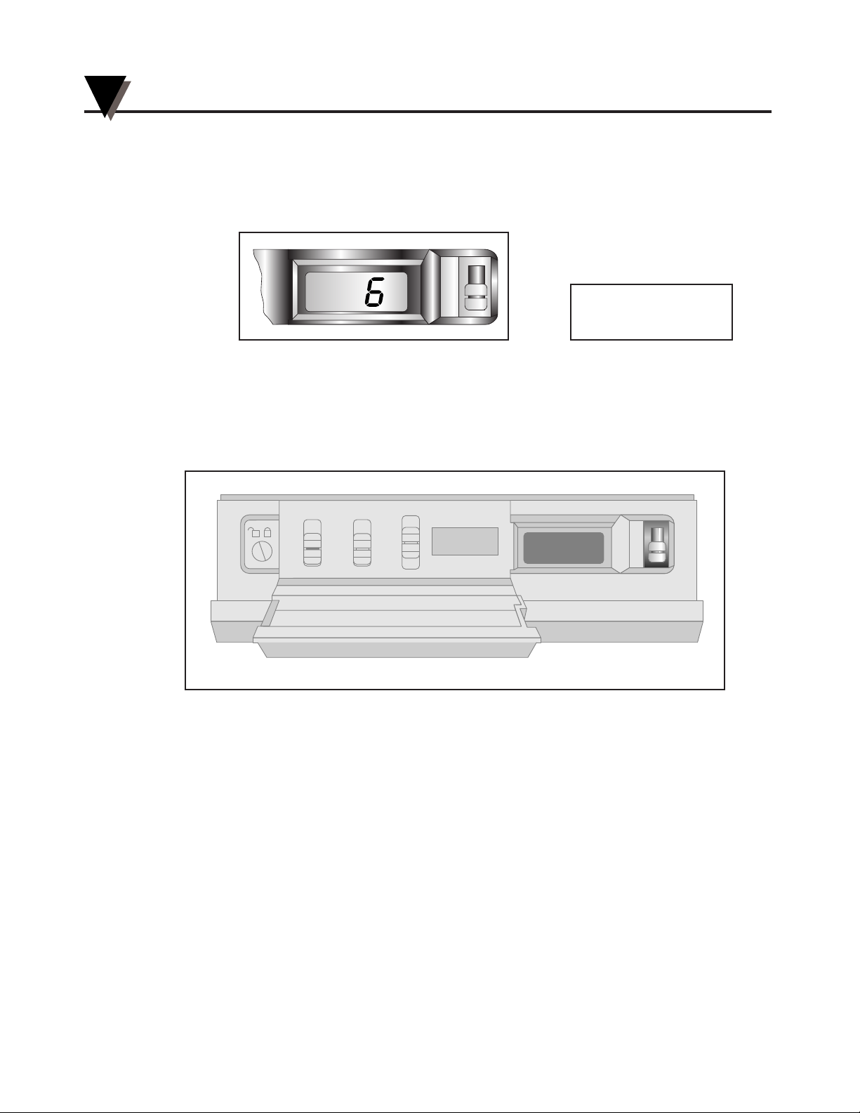
Then, a single-character pH code, a number or letter 0, 1, 2, 3, ... , 8, 9, a, b, or c,
appears. An example is shown in Figure 3-4; the numbers will vary:
Figure 3-4. pH Code
3.3 Final Display Mode
After the pH and temperature codes appear, the LCD displays the current fluid
temperature in °C or the fluid pH, depending on the position of the display
selection switch (refer to Figure 3-8).
Figure 3-8. Display Selector Switch
Initially, the pH recorder pen moves to the right a short distance and then moves
to the left to the zero position. The temperature pen follows. Then, both pens,
one at a time, move to the positions which correspond to the current temperature
and pH.
At this point, the recorder is ready to use.
RH
F
HIGH SET LOW
1
7
32
Normal
Cal
0
I
CHART TYPE
PWR
ALARM
pH
°C
Write your code here
6
pH
°C
Page 29
Alarm Operation
4-1
4
4.1 Alarm Description
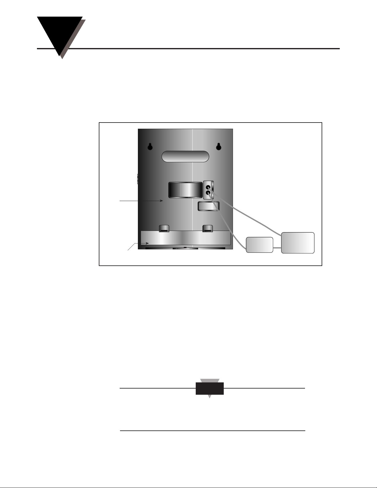
The chart recorder is equipped with an alarm system which is activated when
the sensor conditions exceed user-set limits. The system consists of a built-in
audible piezo-electric beeper and a set of normally open dry relay contacts for
activating an external alarm. The contacts are rated for 1 amp at 35Vdc or 1 amp
at 35Vac. The contact terminals are mounted on the rear of the recorder (refer to
Figure 4-1). In addition, the LCD display will flash upon alarm activation.
Figure 4-1. Alarm/Relay Contacts Location
4.2 Checking Alarm Limits
WAIT UNTIL THE UNIT HAS STABILIZED AND THE PENS STOP MOVING
BEFORE PRESSING ANY KEYS ON THE KEYBOARD.
• Depending on the Display Selection Switch position, the display will
be in °C or pH for the alarm limit viewing.
• The word ‘hi’ and the high limit value of the alarm may be seen on the
display after pressing the “HIGH” button on the front panel.
• The word ‘lo’ and the low limit value of the alarm may be seen on the
display after pressing the “LOW” button on the front panel.
The alarm limits are stored in permanent EEPROM memory
and will not be lost even if power is interrupted and battery
backup fails.
NOTE
Alarm
dc or ac
Power
Supply
Rear
Battery
Compartment
(External Power
Supply And Alarm
Not Included)
Foot Cover Removed
Page 30
4.3 Unlocking/Locking the Control Panel Door
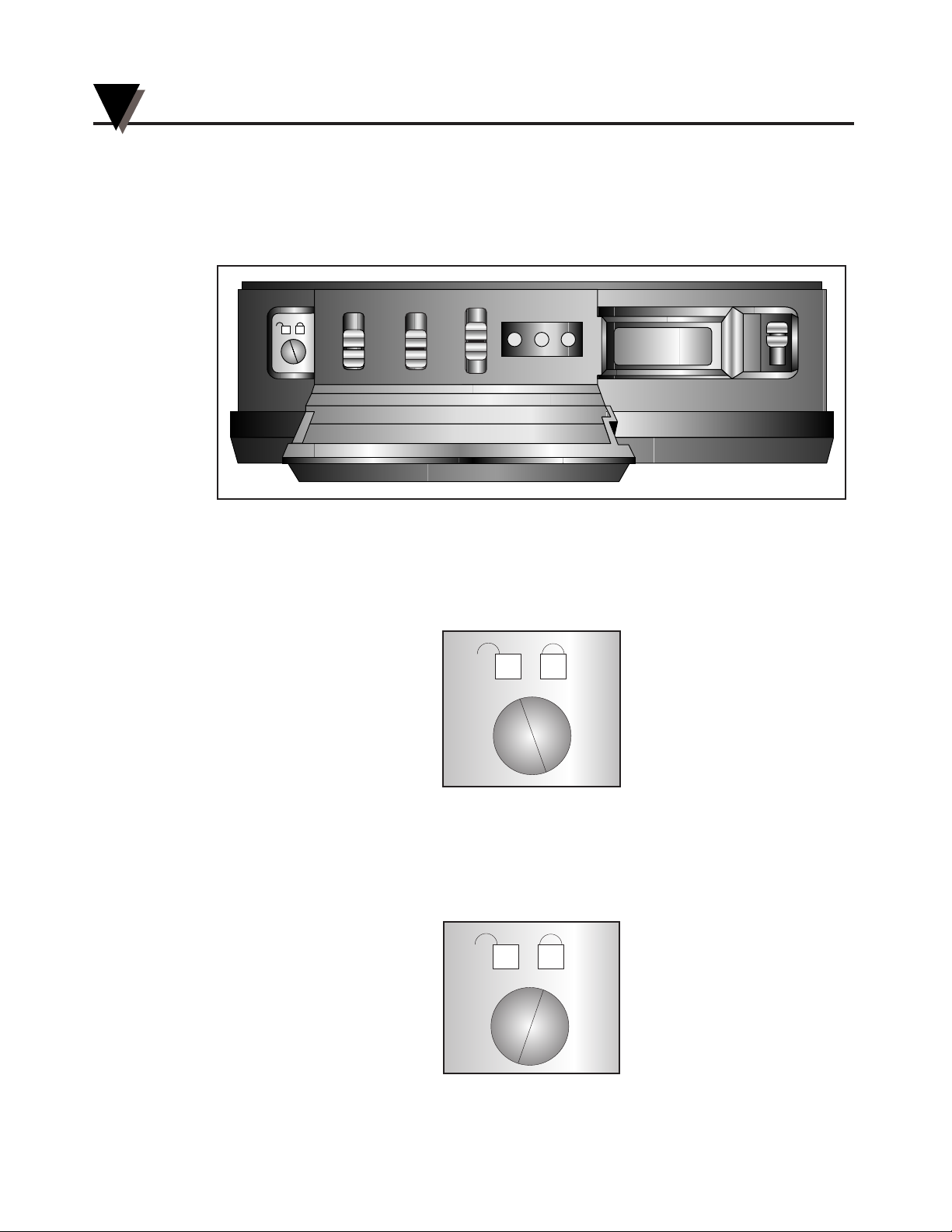
To access the Alarm Display Buttons (Figure 1-1, item #10) under the control
panel door, you may have to unlock the door. You’ll find the control panel door
lock to the left of the control panel. Refer to Figure 4-2.
Figure 4-2. Location of the Door Lock
4.3.1 Unlocking the Control Panel Door
Use a small screwdriver to turn the lock to the left as far as it will go. Figure 4-3
shows the unlocked position.
Figure 4-3. Door Unlock Position
4.3.2 Locking the Control Panel Door
Use a small screwdriver to turn the lock to the right as far as it will go. Figure
4-4 shows the locked position.
Figure 4-4. Door Lock Position
pH
°C
HIGH SET LOW
1
7
32
NORMAL
CAL
0
I
CHART TYPE
PWR
ALARM
7.4
Alarm Operation
4
4-2
Page 31
4.4 Setting/Changing Alarm Limits
To set the alarm limits on the alarm recorder:
1. Set the display selection switch (Figure 1-1, item #12) to pH or °C, depending
on the parameter for which you would like to set the alarm limits. Refer to
Figure 3-8 for the location of the switch.
2. Open the control panel door (unlock it, if necessary).
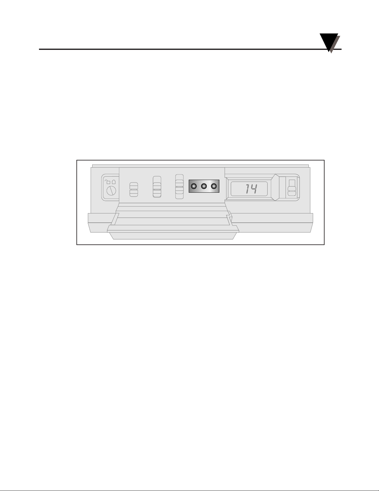
3. Press the “SET” button to activate the display to set either the high OR low
alarm limit. At this time, “SE” is displayed. Figure 4-5 shows the location of the
Alarm Display Buttons.
Figure 4-5. Alarm Display Buttons (HIGH/SET/LOW)
4. Release the “SET” button. The display will alternately flash “hi” and “lo”
repeatedly.
5a. To change the high alarm limit:
• Press and hold the “HIGH” button for 4 seconds, then release.
‘hi’ is displayed and then the current high alarm limit is displayed.
• Press the “HIGH” or “LOW” button to respectively increase or decrease the
value.
• Press the “SET” button to lock in the value(s); the display now shows “SA”.
• Continue to step 6.
5b. To change the low alarm limit:
• Press and hold the “LOW” button for 4 seconds, then release.
‘lo’ is displayed and then the current low alarm limit is displayed.
• Press the “HIGH” or “LOW” button to respectively increase or decrease the
value.
• Press the “SET” button again to lock in the value(s); the display now shows
“SA”.
HIGH SET LOW
1
7
32
NORMAL
CAL
0
I
CHART TYPE
PWR
ALARM
pH
°C
Alarm Operation
4
4-3
Page 32

If, after about 15 seconds, you don’t press the “SET” button to
enter the desired value, the alarm recorder returns the display
to the normal operation.
You can double check your limits at any time by pressing the “HIGH” and
“LOW” buttons.
6. Go through steps 1-5 to check and/or change the limits for the other
parameters. For example, if you already checked or changed °C, you may
check or change pH if you choose.
7. After you are all done with the changes, close and lock the control panel door,
if necessary.
4.5 Turning the Alarm Off
If the high or low alarm limit for pH or temperature is exceeded, you will hear
the alarm. In addition, if the unit is operating under battery power and the
batteries are about to fail, you will hear the alarm.
The alarm will stay on even after the condition which caused the alarm
disappears. Refer to the example below:
pH High Limit Actual pH Alarm Sounding
7.5 7.4 OFF
7.5 7.5 ON (pH rises)
7.5 7.4 ON (pH drops) ***
***The alarm stays on even though the pH drops below the limit.
The alarm recorder will not reset automatically.
1. Unlock the control panel door if necessary.
2. After the alarm becomes activated, the “SET” button must be pressed to disable it.
The message “AO” appears in the display. The alarm is disabled for 10
seconds. After 10 seconds, the alarm may activate again, but only if an
alarm condition is present.
If the alarm is activated and you wish to change the alarm limits:
a. Press the “SET” button for 5 seconds.
First “AO”, then “SE” message will appear in the display.
NOTE
Alarm Operation
4
4-4
Page 33

b. You can now proceed with the changing the alarm limits as described in Section
4.4.
c. After you are all done with the changes, lock the control panel door if
necessary.
4.6 Disabling the Alarm
1. Unlock the control panel door if necessary.
2. On power up, when you hold the “LOW” button down, an “AO” message
appears in the display and the beeper sounds. This will disable the alar
m
function.
(This action sets the high pH limit to 12.1, the low pH limit to 0.1, the high
temperature limit to 99, and the low temperature limit to 01. Since these
limits are outside the normal measuring range of the alarm recorder, the
alarm function is effectively disabled.)
The alarm limits are set this way when you receive the unit. If the alarm is
disabled, you must re-initialize the instrument. After you are done with the
changes, lock the door if necessary.
3. To verify the settings after re-initializing is completed, press the “LOW” button to
get the low value, and the “HIGH” button to get the high value.
Alarm Operation
4
4-5
Page 34

Alarm Operation
4
4-6
Notes
Page 35
Calibrating the Recorder
5-1
5
5.1 Factory Calibration Information
The recorder is factory calibrated during final assembly by calibrating the sensor
(shipped with the recorder) to known temperature and pH standards. This
technique avoids tracking and positioning errors due to temperature changes
and mechanical shock. However, if the pH readings drift or appear out of
calibration, follow Section 5.2 to recalibrate your recorder.
5.2 Changing Calibration Codes
To change the calibration codes:
1. Open the control panel door (unlock it, if necessary).
2. Turn the power switch to the off (“O”) position.
3. Press and hold down the “SET” button while turning on the power switch. This
button is one of three Alarm buttons shown in Figure 4-5.
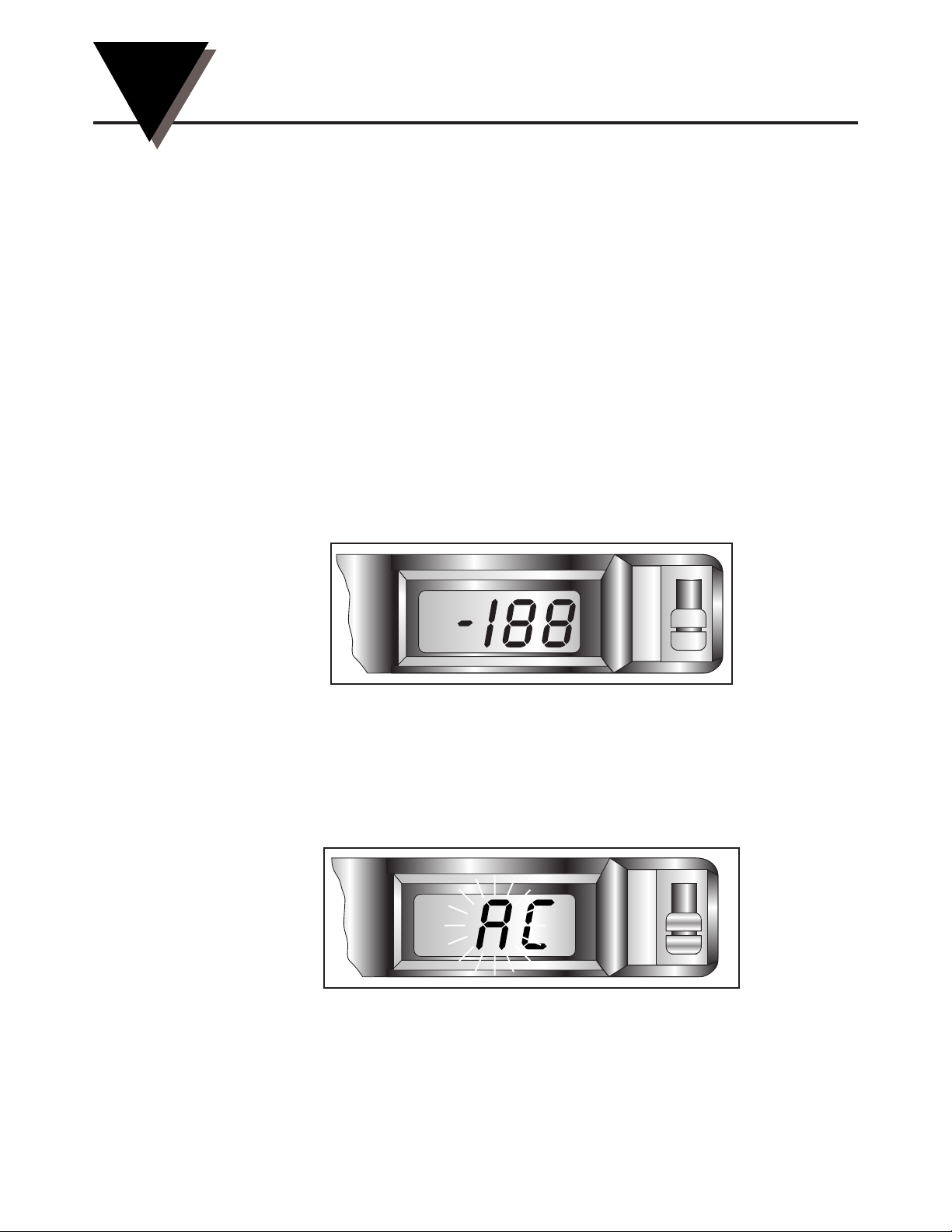
After you hear an audible beep, you will see the following display:
Figure 5-1. First Display
Then “CH” appears on the display.
4. At this time, release the “SET” button.
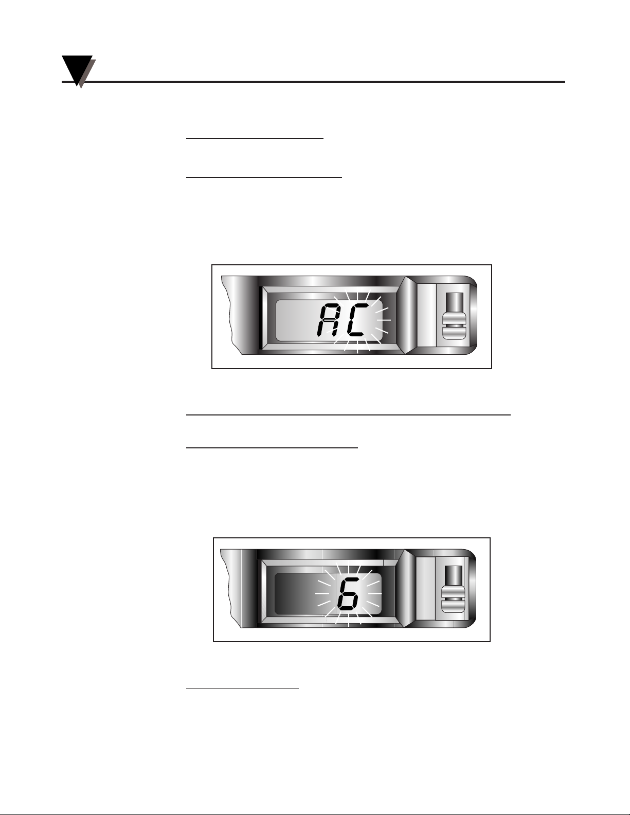
A 2-character temperature calibration code "AC" should now appear in the
display with the first character blinking. Refer to Figure 5-2.
Figure 5-2. Temperature Code - First Character Blinking
pH
°C
pH
°C
LO BAT
Page 36
5a. If the first character is correct,
press the “SET” button and go to step 6.
5b. If the first character is not cor
r
ect,
press the “HIGH” button to increase the value of the character or the
“LOW” button to decrease the value of the character. When this character
is correct, press the “SET” button.
6. The second character should now be blinking. Refer to Figure 5-3. If it is not,
press the “SET” button until it does.
Figure 5-3. Temperature Code - Second Character Blinking
7a. If the second character of the temperature calibration code is correct,
press the “SET” button and go to step 8.
7b. If the second character is not cor
rect,
press the “HIGH” button to increase the value of the character or the
“LOW” button to decrease the value of the character. When this character
is correct, press the “SET” button.
8. A single character pH calibration code "6" should be blinking in the display.
Refer to Figure 5-4. If it is not, press the “SET” button again.
Figure 5-4. Blinking pH Code
9a. If the pH code is cor
rect,
press the “SET” button and go to step 10.
pH
°C
pH
°C
Calibrating the Recorder
5
5-2
Page 37

9b. If the pH code is not correct,
press the “HIGH” button to increase the value of the character or the
“LOW” button to decrease the value of the character. When this character
is correct, press the “SET” button to lock in the values.
At this time, you see the temperature and pH codes on the display as you
entered them. This way, you can verify that you entered them correctly.
10. The unit should now automatically go through the power up sequence as
described in Chapter 3. If it does not, hold down the “SET” button until it does.
While the unit goes through the power up sequence, observe the display to
see that the calibration values are what they should be and that they have
been entered correctly.
11. If either the temperatur
e or pH code is incorrect
,
repeat steps 1-10. After you are all done with the changes, lock the
control panel door, if necessary. Refer to Section 4.3 for details.
5.3 Calibrating pH Readings
In order to calibrate the pH readings you need 7.00 and 4.00 buffer solutions. See
accessories list for ordering information. Start by turning the unit ON and
observing the Display power up routine. After you hear a beep, you will see the
display "LO BAT.-188", than the temperature code "Ac", followed by pH code "6".
Put the display switch on pH.
Immerse the probe in 7.00 buffer solution as shown in figure 5-5. then wait one
minute for the pens to stop moving. Observe the display: it should read 7.0. If it
does not, turn the calibration switch to "CAL" and open the door.
When the probe pens stop moving, turn the "CAL" adjustment to display 7.0,
than put the sensor in 4.00 buffer solution and wait one minute. If the display
doesn't read 4.0, turn the "Slope" adjustment to bring it to 4.0.
Repeat these steps until the readings are correct in both 7.00 and 4.00 buffer
solutions. Now the recorder is calibrated.
Close the door and put the calibration switch on "NORMAL".
Calibrating the Recorder
5
5-3
Page 38
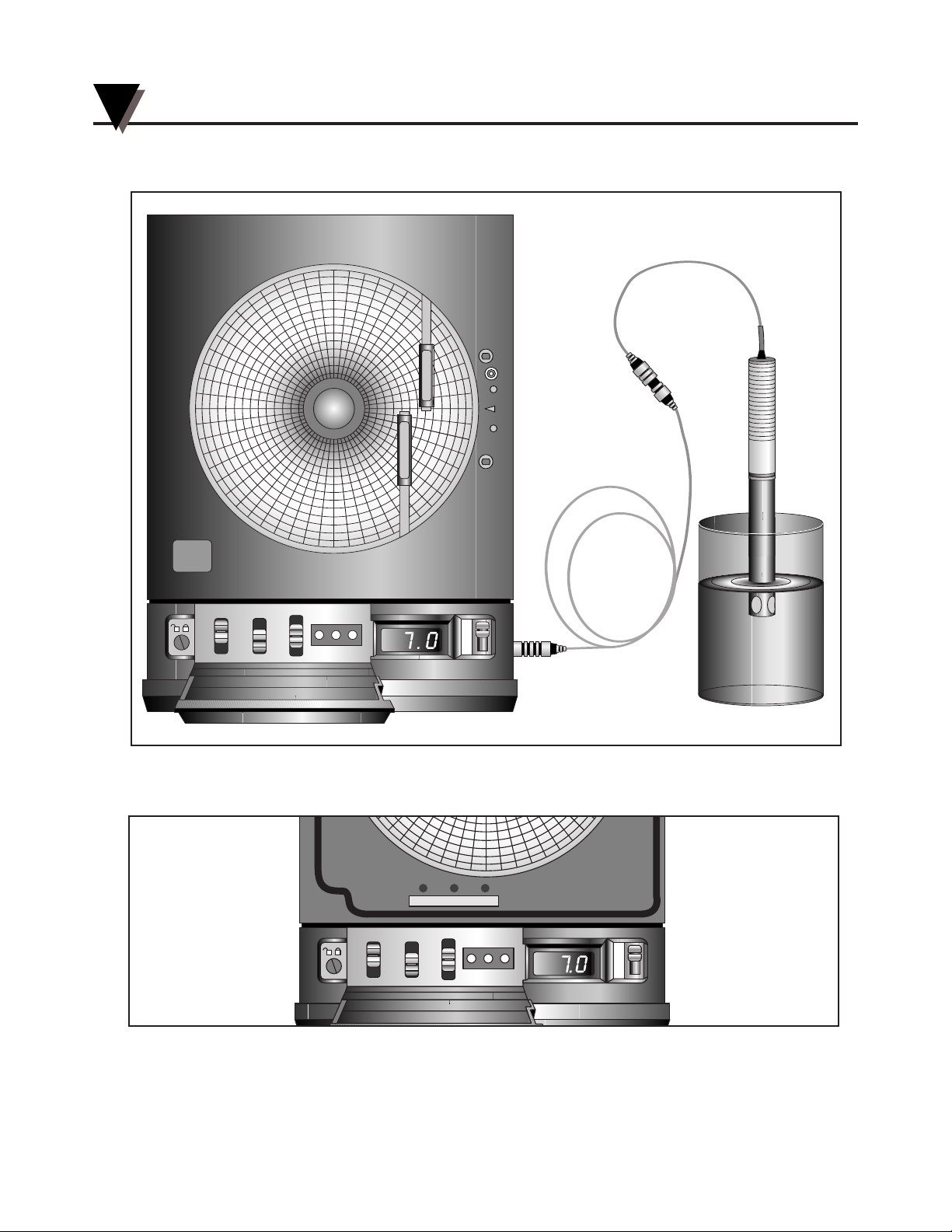
Figure 5-5. Calibration Setup
Calibrating the Recorder
5
5-4
Probe
Remote
Probe
Cable
HIGH SET LOW
1
7
32
Normal
Cal
0
I
CHART TYPE
PWR
ALARM
T
E
M
P
E
R
A
T
U
R
E
pH
°C
Buffer
Solution
P
H
R
E
C
O
R
D
E
R
HIGH SET LOW
1
7
32
Normal
Cal
0
I
CHART TYPE
PWR
ALARM
pH
°C
SLOPE CAL TEMP
Figure 5-6.
Page 39
Using the Cal-Lock Kit
6-1
6
The CT485B-CAL-LOCK kit that comes with the Recorder is used to preserve
and protect the settings that were entered into the unit during the calibration
process. The CT485B-CAL-LOCK cover shields the HIGH, SET and LOW
calibration buttons to prevent any additional button pressing. This method is
more “permanent” than using the control panel door lock. Here’s the procedure:
USE EXTREME CAUTION WHEN USING THE GLUE. READ
THE WARNING LABEL ON THE TUBE.
1. Calibrate the Recorder.
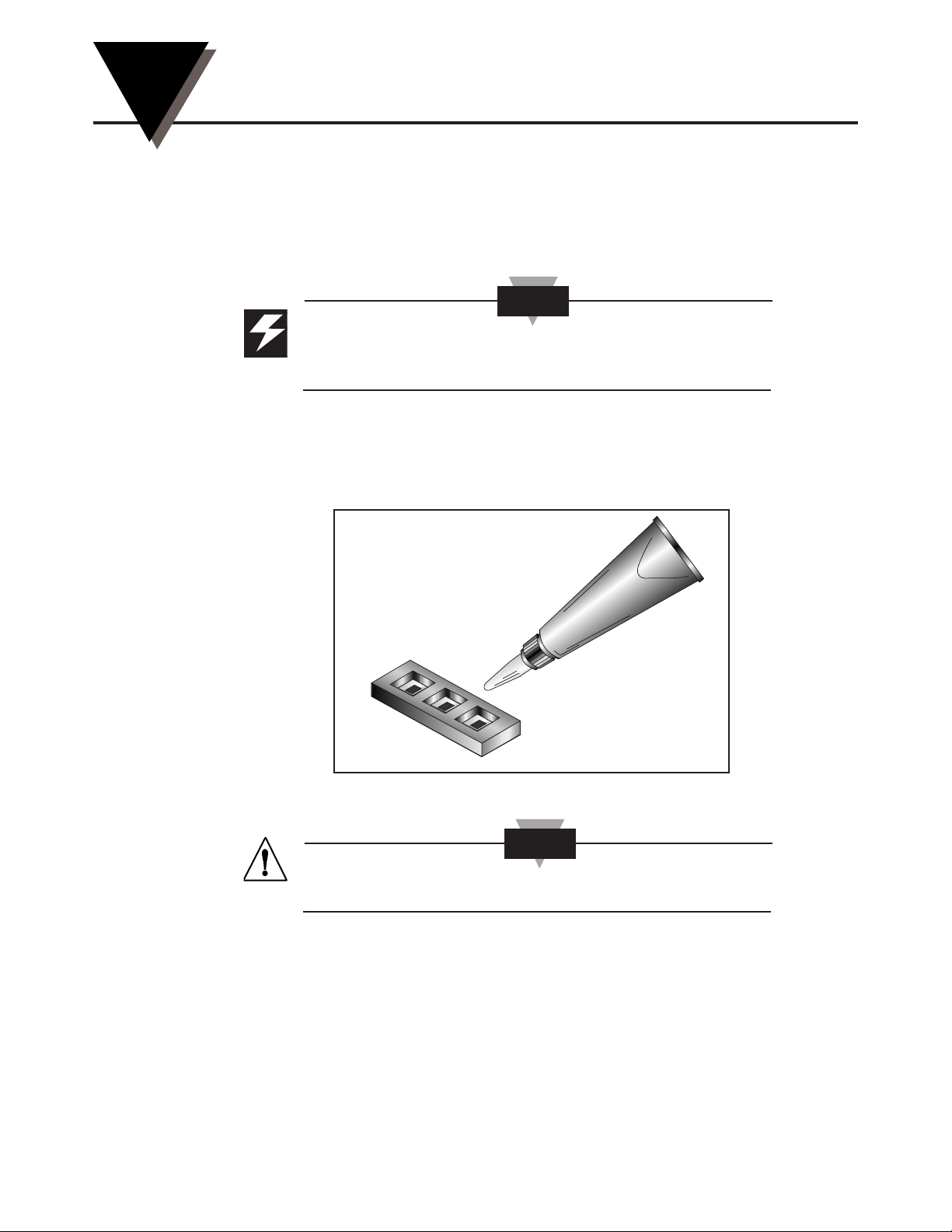
2. Apply a small amount of glue to the back of the cover. Refer to Figure 6-1.
Figure 6-1. Glue Application
DO NOT LET GLUE COME IN CONTACT WITH BUTTONS.
CAUTION
WARNING
Page 40
Using the Cal-Lock Kit
6
6-2
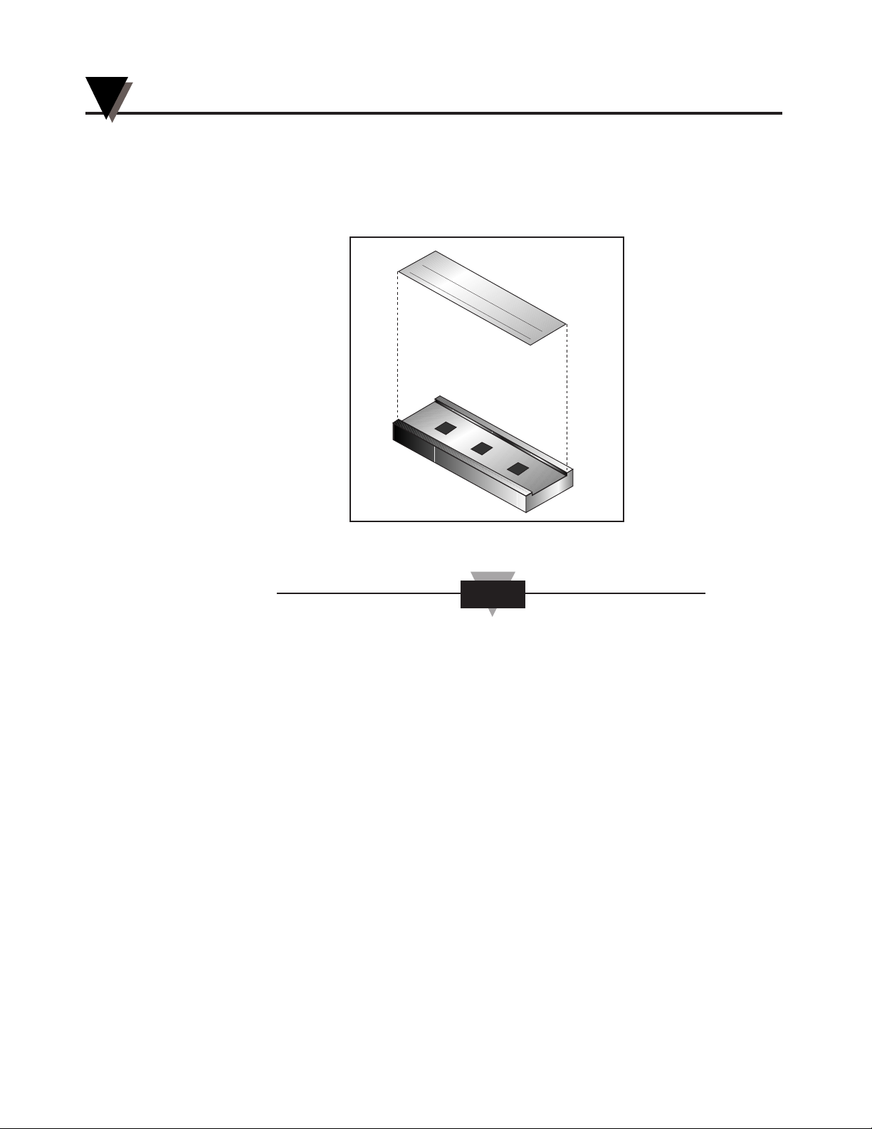
3. Place cover over calibration buttons.
4. Fill in the label information.
5. Apply label to cover as shown in Figure 6-2.
Figure 6-2. Label Application
An additional label is supplied for future calibrations. A damaged label or
removal of the label implies that the calibration of the recorder may have
been altered.
NOTE
CALIBRA
TED
BY:
DA
TE:
Page 41
Using the BNC Input Adapter (Optional)
7-1
7
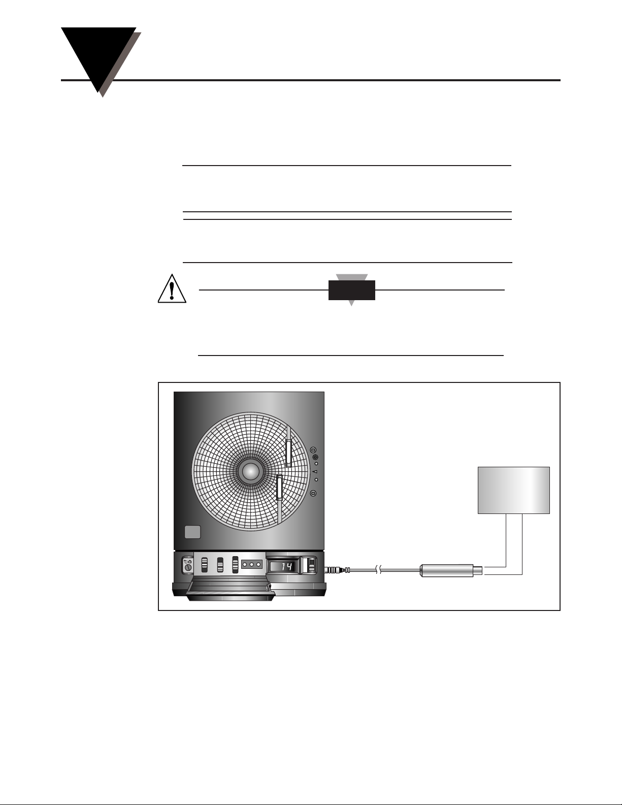
Use the optional BNC input adapter to record pH from a standard BNC probe
without temperature compensation. pH will be recorded per the following table
of inputs:
0 pH 1 pH 2 pH 3 pH 4 pH 5 pH 6 pH
414mV 355mV 296mV 237mV 177mV 118mV 59mV
7 pH 8 pH 9 pH 10 pH 11 pH 12 pH
0mV -59mV -118mV -177mV -237mV -296mV
INPUT VOLTAGES GREATER THAN SPECIFIED MAY
DAMAGE THE RECORDER.
Figure 7-1 shows a typical setup using the BNC adapter.
Figure 7-1. BNC Adapter Setup
CAUTION
Voltage
Source
BNC Adaptor
HIGH SET LOW
1
7
32
Normal
Cal
0
I
CHART TYPE
PWR
ALARM
pH
°C
T
E
M
P
E
R
A
T
U
R
E
P
H
R
E
C
O
R
D
E
R
Page 42

Using the BNC Input Adapter (Optional)
7
7-2
Notes
Page 43
Maintaining the Recorder
8-1
8
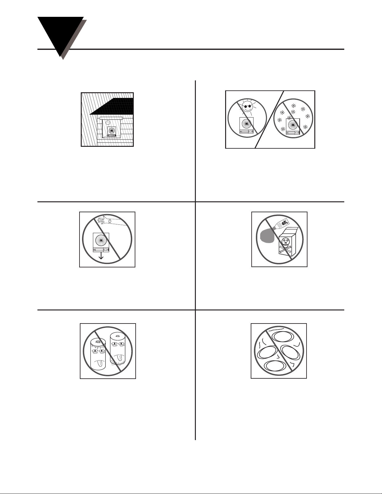
8.1 General Considerations
73
Keep the recorder in a dry place. If it
gets wet, wipe the case as soon as
possible to get rid of any moisture.
Do not expose the recorder to temperatures
other than those stated in the specifications
(Chapter 11). The recorder can operate in
temperatures as high as 120°F (49°C) or as
low as 32°F (0°C).
121
31
73
Handle the recorder carefully
(DO NOT DROP IT).
Keep the recorder away from
excessive dirt and dust.
Do not use strong cleaning solvents or
alcohol when cleaning the outer case. Refer
to Section 8.3 for more details.
Do not use old or weak batteries in
the recorder. It is important to
change the batteries monthly or
when you see the LO BAT indicator
(refer to Section 2.3.1).
SOLVENT
DUST
DUST
DUST
DUST
Page 44
8.2 Light Bulb and Push Button Information
You may notice that the light bulbs flicker slightly while the pens are moving.
The flickering stops once the pens are stationary.
The light bulbs on the chart base of the recorder are long-life specialty bulbs.
Even though they last a very long time, they will burn out eventually. Always
replace both bulbs. The part number for ordering 10 bulb/holder assemblies is
listed on the inside back cover. One extra pair of bulb assemblies is supplied
with the recorder.
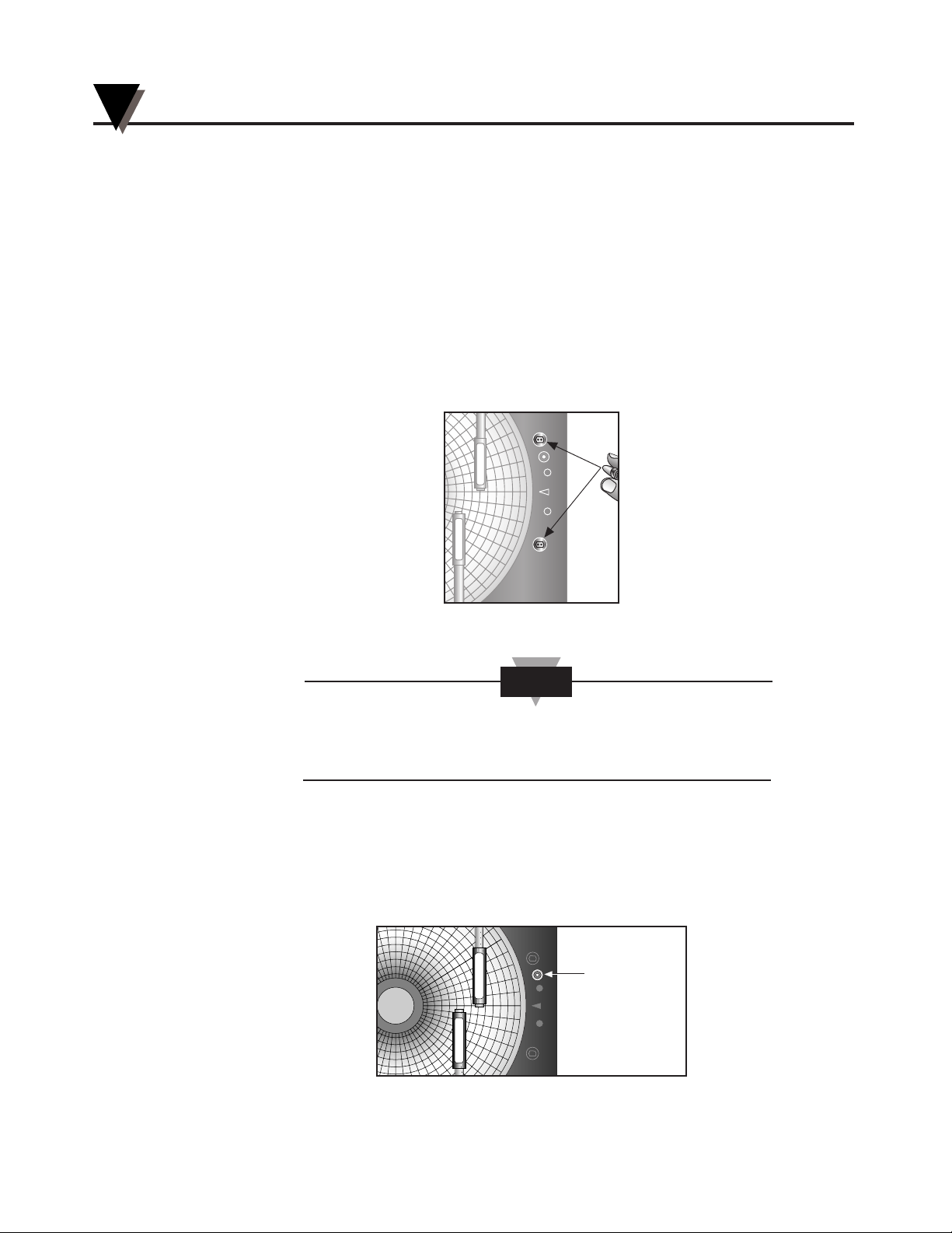
When removing the bulbs, grasp the bulb holder that contains the bulb and pull
it out. Do not pull on the bulb itself. When reinserting the new bulbs in the
sockets, orient the bulbs to fit as shown in Figure 8-1.
Figure 8-1. How to Hold the Bulb Assembly and Where the Bulbs are Located
In the event that the ac power to the recorder is cut off (e.g.,
blackout), the recorder will continue to operate with the 4 “D”
size backup batteries. The bulbs operate on ac power only.
The recorder is equipped with a push button located on the chart base. This push
button turns on and off the light bulbs which are used for illuminating the chart.
The push button also turns on and off the backlighting for the LCD display. One
press of the push button turns on the bulbs and a second press turns them off.
Figure 8-2 shows the location of the push button.
Figure 8-2. Push Button Location
Light Bulb
Push Button
T
E
M
P
E
R
A
T
U
R
E
P
H
R
E
C
O
R
D
E
R
NOTE
T
E
M
P
E
R
A
T
U
R
E
P
H
R
E
C
O
R
D
E
R
Maintaining the Recorder
8
8-2
Page 45
8.3 Case Care
The case, front window and pen arms of the recorder should be cleaned with a
mild soap solution. Under no circumstances should you use an alcohol or
solvent based cleaner anywhere on this recorder.
8.4 Storage of Chart Paper
For optimum performance, store the chart paper in the plastic bag provided.
Store the paper in rooms that have humidity levels lower
than 80% relative
humidity.
8.5 Power Failure Mode (Chart Paper Indication)
The chart paper indicates when the ac power failure occurred, the battery back
up period and when the ac power returns. It is important to have fresh “D” size
batteries in the recorder for battery backup so you have continuous recording.
Figure 8-3 shows an example of chart paper with the power failure lines.
Figure 8-3. ac Power Failure Indication on Chart Paper
Clips
pH
C
P
H
R
E
C
O
R
D
E
R
T
E
M
P
E
R
A
T
U
R
E
Maintaining the Recorder
8
8-3
Page 46

Maintaining the Recorder
8
8-4
Notes
Page 47
Troubleshooting the Recorder
9-1
9
Table 9-1 contains a brief troubleshooting guide.
Table 9-1. Troubleshooting Guide
If this occurs Perform these steps
Make sure the door is completely closed
and the latch button is in the uppermost
position. It may be necessary to squeeze
the case slightly to close the latch completely.
The pens do not appear to
be leaving traces on the
paper.
?
Make sure the “CHART TYPE” 1/7/32
switch is in the correct position.
Make sure the magnetic chart knob is in
place.
Chart paper appears not to
turn, or to turn at the wrong
speed.
?
If using old batteries, replace with a fresh
set of alkaline batteries.
If using fresh batteries, make sure they
are inserted correctly.
Make sure the ac adaptor is securely
plugged into the wall and into the power
jack on the recorder.
Make sure POWER switch is in the “|”
(ON) position.
Recorder appears not to
function at all.
?
Page 48
Table 9-1. Troubleshooting Guide (Cont’d)
If this occurs Perform these steps
E6 occurs when one or more pen arms
are jammed. Check that the pens have
been installed correctly, and that the
chart paper knob is holding the paper
down correctly.
Display “E6”
?
The chart recorder is operating off
batteries. Switch over to ac power if you
wish to light up the paper.
Bulbs are blown. Replace them with new
bulbs.
Bulbs don’t light.
?
Make sure pen caps are removed (and
secured on the cap posts as
recommended).
Check that the pens are locked firmly in
position in their holders.
Make sure the pens are fresh. Remove a
pen and test it on a piece of
chart p
aper.
Insert new pens if necessary.
The pens do not appear to
be leaving traces on the
paper.
?
Troubleshooting the Recorder
9
9-2
Page 49

Xxxx
9
9-3
Page 50

Xxxx
9
9-4
Page 51

Technical Details
10-1
10
10.1 Sensors and Measurement
The recorder has an external plug-in temperature/pH sensor. A six-foot
(1.83 meter) remote probe cable is provided to allow remote sensing of both pH
and temperature.
Unlike many circular recorders, this unit utilizes electronic probe to measure
both fluid pH and temperature. The temperature probe is a 1000 ohm RTD,
which when excited with constant current develops a voltage closely
proportional to temperature. The pH probe consists of two components, the
glass bulb and the reference component. These two compartments develop a
voltage depending upon the pH of the solution in which the probe is immersed.
Applied to a preamplifier, this voltage can be sent over standard wire for
virtually unlimited length.
The electronically-conditioned output of both probes are fed to a microprocessor
via an analog-to-digital converter. The processor linearizes and temperature
compensates the output of the pH circuit employing a “look-up table" approach.
The results of the processor calculations are then used to update the front panel
display and to position the pen arms on the chart paper.
10.2 Pen Arm Drive
This recorder utilizes a motor-driven lead screw pen arm drive located in the
door of the unit. This provides several advantages over conventional pivot arm
mechanisms. First, the recorder pens move along straight, radial lines as the pH
and temperature change. Thus, the time scales on the chart paper are straight
lines and are much easier for the user to interpret than the swooping arcs
produced by a conventional recorder. Second, the placement of the recorder pen
arms directly opposite one another allows the pen tips to be placed very close
together. This minimizes time offset between information recorded by the pH
and temperature pens, making the charts easier to interpret. Finally, the location
of the drive mechanism in the door provides an automatic pen lift when
changing the chart paper.
The position of the pen arms on the lead screw mechanism is controlled by
optical encoders. On power up or system reset, the pen arms move to the zero
position. This is detected by a photo interrupter, to provide absolute positional
information to the microprocessor.
From this point, a count wheel mounted on the lead screw provides positional
information relative to the zero position. There are 32 counts for each division on
the chart paper.
As with all positioning mechanisms, an error may appear in the tracking over a
period of time. To minimize this error, several steps have been taken. First, a
deadband for pen movement of
1
⁄2 chart division has been programmed in to
minimize pen motion without affecting usable chart resolution. Second,
whenever you change chart paper, a magnetic switch detects the opening of
the door and initiates a system reset, thus re-zeroing the pens and eliminating
any accumulated errors.
Page 52

10.3 Chart Paper Drive Mechanism
The recorder incorporates a stepper motor to impart rotational motion to the
chart paper. A novel feature of the unit is its ability to utilize 1, 7 or 32 day chart
paper simply through front panel switching. This capability is provided by a
special digital timing circuit which precisely controls the stepping rate of the
magnetic armature in the motor.
10.4 Power Supply Supervision
The recorder contains power supply monitoring and switching circuitry which
enables it to be used in a variety of circumstances. Under ordinary
circumstances, the unit will be powered by 110 or 220 Vac with the ac adaptor
provided. This is the preferred mode of operation. The recorder can also operate
via 4 “D” size batteries installed in the rear of the unit which will power the
unit up to 30 days.
The system may be restarted by changing the batteries or by the re-initiation of
ac power. If ac power fails, the circuitry will attempt to automatically switch to
battery backup. If viable battery power is available, the system will operate on
battery power until the batteries fail or ac power returns. When ac power
returns, the recorder will automatically reset itself (refer to Section 8.5).
Typically, the unit will operate with fresh alkaline batteries for about 1 month. It
should be noted that to conserve battery power, the system timing turns the
sensors on and updates the display and pen position only once every 0.5, 3.5 or
16 minutes while in the 1, 7 or 32 day modes respectively. However, the display
remains in continuous operation during battery operation. You should be aware,
then, that during battery operation it is possible for the display and pens to lag
behind actual ambient conditions by up to 0.5, 3.5, or 16 minutes to save power.
Only when using the ac adaptor do the pens constantly update for changes in
ambient conditions.
Technical Details
10
10-2
Page 53

Specifications
11-1
11
General
Measurement Input: pH and temperature, with plug-in external sensor
Removable for remote location
pH
Range: 0.2 to 12.0 pH
Accuracy: ±0.1 pH
Probe: Solid State In Line or submersion PPS (Ryton)
Response Time: 30 seconds for 90% of change
Display Resolution: 0.1 pH
Temperature
Range: 0.2 to 80 °C
Accuracy: ±3°C
Sensor: 1000 ohms RTD (incorporated in CTpH-Probe)
Display Resolution: 1°C
Display
Types: 21⁄2 digit LCD, 0.5” high; low battery and
parameter indication, and Back Light with ac
adapter only
Display Modes User-switchable between °C and pH for
continuous display; max/min storage for both
temperature and pH
Electronics
Type: Microprocessor-controlled. HI & LO Peak Hold for
both temperature and pH; re-initializes position
at every chart change (every time door is opened)
Chart Paper
Type: 8 inch (200mm) circular, double-sided, with
linear radial divisions; 1, 7 and 32 day
Chart Drive
Type: Stepper Motor
Ranges: 1, 7, 32 day; switchable
Accuracy: 1% of rotation
Chart Paper Hold Down: Magnetic hub lock
Page 54

Recording Pens
Type: Disposable fiber-tip; green for pH, red for
temperature
Pen Drive
Type: Motorized linear screw drive
Deadband: 1°C, 0.1 pH
Zero: Automatic zero during chart change or power
interruption
Pen Arms: Clear plastic to allow full chart viewing
Pen Lift: Automatic upon door opening; pens are door
mounted and lift away from the chart whenever
the door opens.
Alarms
Alarms: User-selectable for high or low temperature and
pH
Audible Alarm: Integral piezo-electric beeper
Alarm Relay Contacts: Normally Open, Single Pole, Single Throw (SPST)
1A 35Vdc or ac.
Operating Conditions (Recorder)
Temperature: 32° to 120°F (0° to 49°C)
Humidity: 0% to 90% RH, non-condensing
Operating Conditions (Remote Probe)
Temperature: 0° to 80°C
pH: 0 to 12 pH
Specifications
11
11-2
Page 55

Power (Recorder)
dc: Four (4) “D” size alkaline batteries; greater than
1 month continuous operation in 32 day mode;
bulbs will not light on battery power.
Recommended battery type: Duracell Type
MN1300 “D” size batteries for best performance
at low temperatures.
ac: 110Vac or 220Vac 50/60 Hz stepped down to
nominal 9Vdc using ac adaptor provided
Power 300 mA “normal” during pen movement for
Requirements: battery (dc power); 500 mA “normal” during pen
movement for ac power using ac adaptor.
(Note: The light bulbs draw 200 mA of current).
ac Power Jack 8.3 to 12.4 Vdc, (nominal 9Vdc) 1A max.
Voltage: An ac adaptor is supplied
Mechanical
Dimensions: 133⁄16” x 1011⁄16” x 25⁄8”
(H x W x D) (33.5 x 27.1 x 6.7 cm)
Weight: Approx. 7 lbs, including alkaline batteries
Mounting: “Keyhole” slots for wall mounting; foot cover for
benchtop use
Case: Rugged ABS plastic, color: gray
Miscellaneous: Swing-out stabilizing arm for bench top use,
decorative foot cover for wall mounting, and 10
ft remote probe cable for remote sensing.
Specifications
11
11-3
Page 56

Specifications
11
11-4
Notes
Page 57

Index
l
I
A
Accessories ................. Inside Back Cover
ac Adapter ............................................. 2-5
ac Power Failure Indication ................ 8-3
ac Power Hookup ................................. 2-5
Alarm Display Buttons ................ 1-3, 4-3
HIGH ................................... 1-3, 4-3
LOW .................................... 1-3, 4-3
SET ....................................... 1-3, 4-3
Alarm Limits ......................................... 4-1
Disabling the alarm .................. 4-4
Setting the alarm ....................... 4-3
Turning off the alarm ............... 4-4
Operation of .............................. 4-5
Alarm/Relay Contacts ................. 1-4, 4-1
B
Batteries (“D” size) ............................... 2-4
Installing .................................... 2-4
Replacing ................................... 2-4
Battery Compartment .................. 1-4, 2-4
Battery Usage
Indication on Paper .................. 8-3
Bench Top Use ...................................... 2-1
BNC Input Adapter Option..................7-1
Bulb Replacement ................................ 8-2
C
Calibrating ............................................ 5-3
Codes ................................... 3-1, 5-1
Calibration Lock Out Labels ................6-1
Cal-Lock Kit .......................................... 6-1
Care of
Bulbs ........................................... 8-2
Case ............................................ 8-3
Chart Paper ................................ 8-3
Carrying Slot ......................................... 1-4
Chart Paper Knob, magnetic ....... 1-2, 2-7
Chart Paper
Installing .................................... 2-6
Standard ..................................... 1-2
Codes
Probe ........................................... 3-1
Temperature .............................. 3-1
Consumables .............. Inside Back Cover
Control Panel Door Lock ............. 1-3, 4-2
Control Panel Door
Locking ....................................... 4-2
Unlocking .................................. 4-2
Cover for feet & stabilizing arm . 1-3, 2-1
D
“D” size Batteries ................................. 2-4
Display ................................................... 1-3
Display Mode (°C/pH) ....................... 3-2
Displays
LO BAT ...................................... 2-5
System Shut Down ................... 2-5
Latch Button (Door Release) ............... 1-3
F
Foot Cover ..................................... 1-3, 2-1
H
HIGH Button ................................. 1-3, 4-3
I
Installing
Batteries ...................................... 2-4
Chart Paper ................................ 2-6
Pens ............................................. 2-8
pH/Temperature Probe ........ 2-11
Page 58

J
Jack, ac power ....................................... 1-3
L
Latch Button for Door ..........................1-3
LCD Display ......................................... 1-3
Lock for Control Panel Door ....... 1-3, 4-2
Lock Out Labels .. 6-1, Inside Back Cover
Low Battery Warning .......................... 2-5
LOW Button ................................... 1-3, 4-3
M
Maintenance of Recorder .................... 8-1
Mounting Holes (“Keyhole”) ............. 1-4
O
ON/OFF Switch ............................ 1-3, 3-1
P
Pen Cap Posts ................................ 1-2, 2-9
Pen Holders ........................................ 2-10
Pen Replacing ....................................... 2-8
Pen Types
Green (pH) ................................. 2-7
Red (Temperature) ................... 2-7
pH Probe .............................................. 2-11
Power
ac ................................................. 2-5
Battery ........................................ 2-4
dc ................................................. 2-4
Power Failure Indication on Paper .... 8-3
Power Switch ................................. 1-3, 3-1
Powering Up the Recorder ................. 3-1
Product Specifications ....................... 11-1
Push Button (Light Bulb) .................... 8-2
R
Relay/Alarm Contacts ........................ 4-1
Remote Cable ...................................... 2-12
Removing the Pens ............................ 2-10
Replacing the Bulbs ............................. 8-2
S
Sensor:
Codes .......................................... 3-1
Correct Position ...................... 2-11
pH/Temperature .................... 2-11
SET Button ..................................... 1-3, 4-3
Spare Parts .................. Inside Back Cover
Specifications ...................................... 11-1
Stabilizing Arm .................................... 2-7
Switches
Power .......................................... 1-3
pH/°C ........................................ 1-3
1/7/32 day ................................ 1-3
T
Technical Information ....................... 10-1
Temperature Code ............................... 3-1
Time Set Arrow ............................. 1-2, 2-7
Troubleshooting Guide ....................... 9-1
V/W
Wall Mounting ..................................... 2-3
Index
I
II
Page 59

PATENT NOTICE: This product is covered by one or more of the following patents: U.S. PAT. 5,019,838: D311,695/
CANADA 1,306,452; 1,319,925; 65,619 D OMEGA ENGINEERING, INC./GERMANY M 88 03 842.4/KOREA
102,879/ROC PATENT NO. 22507/U.K. REGISTERED 1 055 583
WARRANTY/DISCLAIMER
OMEGA ENGINEERING, INC. warrants this unit to be free of defects in materials and workmanship for a
period of 13 months from date of purchase. OMEGA’s WARRANTY adds an additional one (1) month
grace period to the normal one (1) year product warranty to cover handling and shipping time. This
ensures that OMEGA’s customers receive maximum coverage on each product.
If the unit malfunctions, it must be returned to the factory for evaluation. OMEGA’s Customer Service
Department will issue an Authorized Return (AR) number immediately upon phone or written request.
Upon examination by OMEGA, if the unit is found to be defective, it will be repaired or replaced at no
charge. OMEGA’s WARRANTY does not apply to defects resulting from any action of the purchaser, including but not limited to mishandling, improper interfacing, operation outside of design limits,
improper repair, or unauthorized modification. This WARRANTY is VOID if the unit shows evidence of
having been tampered with or shows evidence of having been damaged as a result of excessive corrosion;
or current, heat, moisture or vibration; improper specification; misapplication; misuse or other operating
conditions outside of OMEGA’s control. Components in which wear is not warranted, include but are not
limited to contact points, fuses, and triacs.
OMEGA is pleased to offer suggestions on the use of its various products. However,
OMEGA neither assumes responsibility for any omissions or errors nor assumes liability for any
damages that result from the use of its products in accordance with information provided by
OMEGA, either verbal or written. OMEGA warrants only that the parts manufactured by the company will be as specified and free of defects. OMEGA MAKES NO OTHER WARRANTIES OR
REPRESENTATIONS OF ANY KIND WHATSOEVER, EXPRESSED OR IMPLIED, EXCEPT THAT OF
TITLE, AND ALL IMPLIED WARRANTIES INCLUDING ANY WARRANTY OF MERCHANTABILITY
AND FITNESS FOR A PARTICULAR PURPOSE ARE HEREBY DISCLAIMED. LIMITATION OF
LIABILITY: The remedies of purchaser set forth herein are exclusive, and the total liability of
OMEGA with respect to this order, whether based on contract, warranty, negligence,
indemnification, strict liability or otherwise, shall not exceed the purchase price of the
component upon which liability is based. In no event shall OMEGA be liable for
consequential, incidental or special damages.
CONDITIONS: Equipment sold by OMEGA is not intended to be used, nor shall it be used: (1) as a “Basic
Component” under 10 CFR 21 (NRC), used in or with any nuclear installation or activity; or (2) in medical
applications or used on humans. Should any Product(s) be used in or with any nuclear installation or
activity, medical application, used on humans, or misused in any way, OMEGA assumes no responsibility
as set forth in our basic WARRANTY/DISCLAIMER language, and, additionally, purchaser will indemnify
OMEGA and hold OMEGA harmless from any liability or damage whatsoever arising out of the use of the
Product(s) in such a manner.
RETURN REQUESTS/INQUIRIES
Direct all warranty and repair requests/inquiries to the OMEGA Customer Service Department. BEFORE
RETURNING ANY PRODUCT(S) TO OMEGA, PURCHASER MUST OBTAIN AN AUTHORIZED RETURN
(AR) NUMBER FROM OMEGA’S CUSTOMER SERVICE DEPARTMENT (IN ORDER TO AVOID
PROCESSING DELAYS). The assigned AR number should then be marked on the outside of the return
package and on any correspondence.
The purchaser is responsible for shipping charges, freight, insurance and proper packaging to prevent
breakage in transit.
FOR W
ARRANTY
RETURNS, please have the
following information available BEFORE
contacting OMEGA:
1. Purchase Order number under which the product
was PURCHASED,
2. Model and serial number of the product under
warranty, and
3. Repair instructions and/or specific problems
relative to the product.
FOR NON-WARRANTY REPAIRS,
consult OMEGA
for current repair charges. Have the following
information available BEFORE contacting OMEGA:
1. Purchase Order number to cover the COST
of the repair,
2. Model and serial number of the product, and
3. Repair instructions and/or specific problems
relative to the product.
OMEGA’s policy is to make running changes, not model changes, whenever an improvement is possible. This affords
our customers the latest in technology and engineering.
OMEGA is a registered trademark of OMEGA ENGINEERING, INC.
© Copyright 2005 OMEGA ENGINEERING, INC. All rights reserved. This document may not be copied, photocopied,
reproduced, translated, or reduced to any electronic medium or machine-readable form, in whole or in part, without the
prior written consent of OMEGA ENGINEERING, INC.
Page 60

M2309/0405
Where Do I Find Everything I Need for
Process Measurement and Control?
OMEGA…Of Course!
Shop online at omega.com
TEMPERATURE
Thermocouple, RTD & Thermistor Probes, Connectors, Panels & Assemblies
Wire: Thermocouple, RTD & Thermistor
Calibrators & Ice Point References
Recorders, Controllers & Process Monitors
Infrared Pyrometers
PRESSURE, STRAIN AND FORCE
Transducers & Strain Gages
Load Cells & Pressure Gages
Displacement Transducers
Instrumentation & Accessories
FLOW/LEVEL
Rotameters, Gas Mass Flowmeters & Flow Computers
Air Velocity Indicators
Turbine/Paddlewheel Systems
Totalizers & Batch Controllers
pH/CONDUCTIVITY
pH Electrodes, Testers & Accessories
Benchtop/Laboratory Meters
Controllers, Calibrators, Simulators & Pumps
Industrial pH & Conductivity Equipment
DATA ACQUISITION
Data Acquisition & Engineering Software
Communications-Based Acquisition Systems
Plug-in Cards for Apple, IBM & Compatibles
Datalogging Systems
Recorders, Printers & Plotters
HEATERS
Heating Cable
Cartridge & Strip Heaters
Immersion & Band Heaters
Flexible Heaters
Laboratory Heaters
ENVIRONMENTAL
MONITORING AND CONTROL
Metering & Control Instrumentation
Refractometers
Pumps & Tubing
Air, Soil & Water Monitors
Industrial Water & Wastewater Treatment
pH, Conductivity & Dissolved Oxygen Instruments
 Loading...