

Page 1
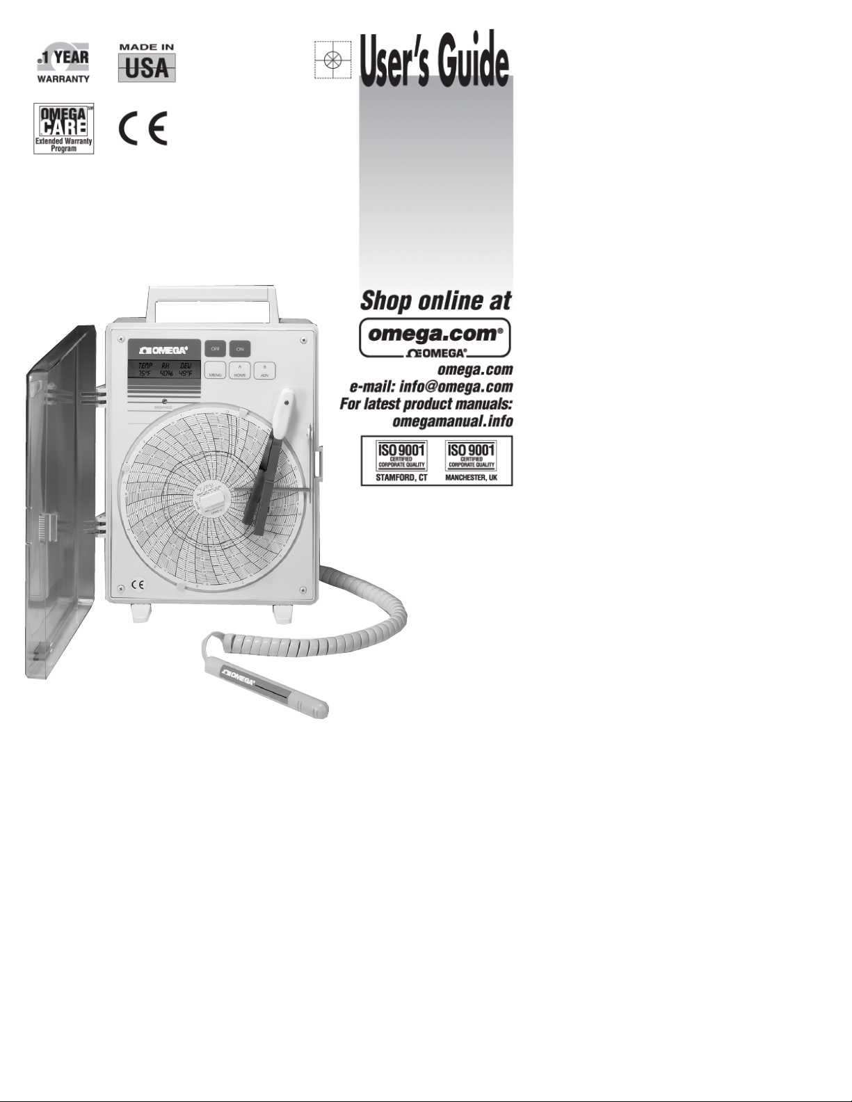
CTH89
RECORDER with TEMPERATURE HUMIDITY DEW POINT KIT
Page 2

It is the policy of OMEGA Engineering, Inc. to comply with all worldwide safety and EMC/EMI regulations that apply. OMEGA is constantly pursuing certification of its
products to the European New Approach Directives. OMEGA will add the CE mark to every appropriate device upon certification.
The information contained in this document is believed to be correct, but OMEGA accepts no liability for any errors it contains, and reserves the right to alter specifications without notice.
WARNING: These products are not designed for use in, and should not be used for, human applications.
WARRANTY/DISCLAIMER
OMEGA ENGINEERING, INC. warrants this unit to be free of defects in materials and workmanship for a period of 13 months from date of purchase.
OMEGA’s WARRANTY adds an additional one (1) mo nth grace period to the normal one ( 1) ye ar p roduct warranty to cover handling an d
shipping time. This ensures that OMEGA’s customers receive maximum coverage on each product.
If the unit malfunctions, it must be returned to the factory for evaluation. OMEGA’s Customer Service Department will issue an Authorized Return (AR)
number immediately upon phone or written request. Upon examination by OMEGA, if the unit is found to be defective, it will be repaired or replaced
at no charge. OMEGA’s WARRANTY does not apply to defects resulting from any action of the purchaser, including but not limited to mishandling,
improper interfacing, operation outside of design limits, improper repair, or unauthorized modification. This WARRANTY is VOID if the unit shows
evidence of having been tampered with or shows evidence of having been damaged as a result of excessive corrosion; or current, heat, moisture or
vibration; improper specification; misapplication; misuse or other operating conditions outside of OMEGA’s control. Components in which wear is not
warranted, include but are not limited to contact points, fuses, and triacs.
OMEGA is pleased to offer suggestions on the use of its various products. However, OMEGA neither assumes responsibility for any
omissions or errors nor assumes liability for any damages that result from the use of its products in accordance with information provided
by OMEGA, either verbal or written. OMEGA warrants only that the parts manufactured by the company will be as specified and free of
defects. OMEGA MAKES NO OTHER WARRANTIES OR REPRESENTATIONS OF ANY KIND WHATSOEVER, EXPRESSED OR IMPLIED, EXCEPT
THAT OF TITLE, AND ALL IMPLIED WARRANTIES INCLUDING ANY WARRANTY OF MERCHANTABILITY AND FITNESS FOR A PARTICULAR
PURPOSE ARE HEREBY DISCLAIMED. LIMITATION OF LIABILITY: The remedies of purchaser set forth herein are exclusive, and the total
liability of OMEGA with respect to this order, whether based on contract, warranty, negligence, indemnification, strict liability or otherwise,
shall not exceed the purchase price of the component upon which liability is based. In no event shall OMEGA be liable for consequential,
incidental or special damages.
CONDITIONS: Equipment sold by OMEGA is not intended to be used, nor shall it be used: (1) as a “Basic Component” under 10 CFR 21 (NRC), used in
or with any nuclear installation or activity; or (2) in medical applications or used on humans. Should any Product(s) be used in or with any nuclear
installation or activity, medical application, used on humans, or misused in any way, OMEGA assumes no responsibility as set forth in our basic
WARRANTY/ DISCLAIMER language, and, additionally, purchaser will indemnify OMEGA and hold OMEGA harmless from any liability or damage
whatsoever arising out of the use of the Product(s) in such a manner.
Servicing North America:
U.S.A.: Omega Engineering, Inc., One Omega Drive, P.O. Box 4047
ISO 9001 Certified Stamford, CT 06907-0047
Canada: 976 Bergar
Laval (Quebec), H7L 5A1 Canada
Toll-Free: 1-800-826-6342 TEL: (514) 856-6928
FAX: (514) 856-6886 e-mail: [email protected]
For immediate technical or application assistance:
U.S.A. and Canada: Sales Service: 1-800-826-6342/1-800-TC-OMEGA
®
Customer Service: 1-800-622-2378/1-800-622-BEST
®
Engineering Service: 1-800-872-9436/1-800-USA-WHEN
®
Mexico/ En Español: 001 (203) 359-7803 FAX: 000 (203) 359-7807
Latin America [email protected] e-mail:[email protected]
OMEGAnet®Online Service Internet e-mail
omega.com [email protected]
Servicing Europe:
Benelux: Managed by the United Kingdom Office
Czech Republic: Frystatska 184
733 01 Karviná, Czech Republic
Toll-Free: 0800-1-66342 TEL: +420-59-6311899
FAX: +420-59-6311114 e-mail: [email protected]
France: Managed by the United Kingdom Office
Toll-Free: 0800 466 342 TEL: +33 (0) 161 37 29 00
FAX: +33 (0) 130 57 54 27 e-mail: [email protected]
Germany/Austria: Daimlerstrasse 26, D-75392 Deckenpfronn, Germany
Toll-Free: 0800 6397678 TEL: +49 (0) 7056 9398-0
FAX: +49 (0) 7056 9398-29 e-mail: [email protected]
United Kingdom: OMEGA Engineering Ltd.
ISO 9001 Certified One Omega Drive, River Bend Technology Centre, Northbank
Irlam, Manchester M44 5BD United Kingdom
Toll-Free: 0800-488-488 TEL: +44 (0) 161 777-6611
FAX: +44 (0) 161 777-6622 e-mail: [email protected]
RETURN REQUESTS / INQUIRIES
Direct all warranty and re pair requests/inqui ries to the OMEGA Customer Service Department . BE FORE RETURNING ANY P RODUCT(S) TO
OMEGA, PURCHASER MUST OBTAIN AN AUTHORIZED RETURN (AR) NUMBER FROM OMEGA’S CUSTOMER SERVICE DEPARTMENT (IN ORDER
TO AVOID PROCE SSING DELAYS ). The assign ed AR n umber shoul d th en be m arked on the outsid e o f th e re turn pack age and on any
correspondence.
The purchaser is responsible for shipping charges, freight, insurance and proper packaging to prevent breakage in transit.
FOR WARRANTY
RETURNS, please have the following information
available BEFORE contacting OMEGA:
1. Purchase Order number under which the product was PURCHASED,
2. Model and serial number of the product under warranty, and
3. Repair instructions and/or specific problems relative to the product.
FOR NON-WARRANTY REPAIRS,
consult OMEGA for current repair charges.
Have the following information available BEFORE contacting OMEGA:
1. Purchase Order number to cover the COST of the repair,
2. Model and serial number of the product, and
3. Repair instructions and/or specific problems relative to the product.
OMEGA’s policy is to make running changes, not model changes, whenever an imp rovement is possible. This affords our customers the latest in technology and
engineering. OMEGA is a registered trademark of OMEGA ENGINEERING, INC.
© Copyright 2011 OMEGA ENGINEERING, INC. All rights reserved. This document may not be copied, photocopied, reproduced, translated, or reduced to any electronic
medium or machine-readable form, in whole or in part, without the prior written consent of OMEGA ENGINEERING, INC.
2
Page 3
3
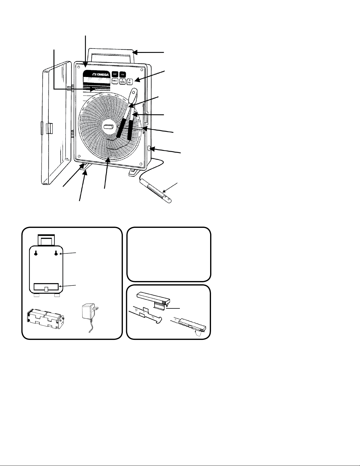
FRONT VIEW
LARGE DESCRIPTION
DISPLAY
DISPLAY BRIGHTNESS
ADJUSTMENTS
FOLD AWAY
CARRYING HANDLE
FRONT MOUNTED
FLUSH CONTROLS
BLUE PEN
(DEW POINT & HUMIDITY)
RED PEN (TEMP)
PEN LIFTER
REMOTE
SENSING PROBE
(HUMIDITY &
TEMPERATURE &
DEWPOINT)
12 VDC JACK
FOR POWER
ADAPTER
BUILT-IN FLUSH
TABLE LEGS
EXTRA SUPPORT
ADD ON LEGS
EASY TO READ 6” CHART
CHANGING PENS
BATTERY HOLDER
PLUG-IN AC
ADAPTER
LATCH
TWO REAR KEYWAY
SLOTS FOR WALL
MOUNTING
COMPARTMENT FOR
BATTERY ACCESS &
PROBE JACK
PEN ARM DATA
The pen arm acts like a flat spring in
order to insure the proper pen-to-chart
pressure. The pen arm is fastened to
the shaft with a set screw. It does not
normally require removal. If removal
becomes necessary, use an Allen .035
Hex Wrench.
REAR VIEW
Page 4

CTH89 RECORDER
WITH TEMPERATURE/HUMIDITY DEW POINT SENSOR
The CTH89 is a precision, multifunction chart recorder. With the sensor kit, the CTH89
becomes a temperature, relative humidity and dew point recorder with a digital display. The
recorder was designed with the user in mind. No special knowledge is required to operate
the CTH89. The menu driven setup is logically simple and user friendly. All parameters are
shown on a two line alphanumeric LCD display. The back lighting of the display enhances
visibility under marginal lighting conditions.
The CTH89 uses two independent pens and records information on a 6 inch circular chart.
Each pen is uniquely colored to maximize chart readability. The rotation of the chart may be
set to Single Turn or Continuous.
In addition, a full function alarm feature is provided. The alarm of the CTH89 can be set
to sound an audible signal when the temperature and/or humidity has exceeded an upper
or lower limit. Each limit is individually set from the front panel. A delay time before the
alarm is activated may be set by the user to prevent nuisance alarms. Low power normally
open relay contacts are provided to allow activation of a remote alarm, phone dialer or
annunciator. An optional RS-232 port allows connection to a computer for data logging or
monitoring purposes.
Power is supplied through a 120VAC 50/60 Hz. plug-in adapter. External power may be
supplied from any 12VDC source such as automotive, marine, or other battery. Battery
backup for 48 hours is featured to provide operation during temporary power loss.
All functions of the CTH89 are accessed through five pushbuttons located on the front
panel. Selectable functions are retained in a memory to avoid re-entering settings in the
event of a power failure.
QUICK START
1. Connect power supply to CTH89 through jack on right side of unit.
2. Plug power supply into 120VAC outlet.
3. Press ON button.
4. Pens will move to the “Home” position.
(The outermost part of the chart.)
5. Pens will move to a position on the chart according to the display
reading. This is called the RUN Mode. (Unit is always in the ON or
RUN Mode when display is showing temperature, humidity
and Dew Point readings.)
4
Page 5

MENU OR RUN?
The CTH89 has two basic modes of operation:
MENU mode. To review or change settings.
RUN mode. To display present conditions and record them.
If MENU mode is selected, the user can:
Set Chart Speed/Range.
Set red pen to record Temperature or Dew Point.
Set Single or Continuous Chart Rotation.
Set Alarm Status (Alarm delay section of MENU will not show
when the alarm is disabled.):
Alarm Delay = 0
Alarm Delay = 10 Minutes /20 Minutes /1 Hour /2 Hours
If the ALARM is enabled, the following menu selections will be
available:
Set Temperature High Limit
Set Temperature Low Limit.
Set Humidity High Limit.
Set Humidity Low Limit.
After menu setting, unit will automatically go into the RUN Mode after
30 seconds.
If the RUN mode is selected: The display will show Temperature, Humidity,
and Dew Point.
While in the RUN mode, the user can:
Home the pens by pressing the HOME switch. (Allows for easy changing of
charts and pens.)
Set blue pen position.
Set red pen position.
Advance the chart by pressing the ADV button. (To match present time with
chart.)
How to Change the Chart
1. Press the HOME button to move the pens to the outer edge of the chart.
2. Lift the pens with the lever. (Just enough to lift the pens from the chart.)
3. Remove the old chart.
4. Install the new chart on to the spindle.
5. Rotate the chart to the star ting point with the ADV button.
6. Lower the pens.
7. Press the MENU button. This will put Recorder in the RUN Mode.
8. If the pen(s) position needs adjustment, see Pen Adjustment section below.
5
Page 6

CHART SPEED AND RANGE
The CTH89 offers 42 combinations of Chart Ranges and Chart Speeds to match a wide
variety of applications. All functions of Chart Speed and Chart Range have been combined
in one menu to make the necessary selections as easy and as fast as possible. A further
aid to the user is the Omega chart number shown on the display for any combination of
Chart Range and Chart Speed.
Chart Speed is the term used to describe the time it takes for the recording chart to make
one complete revolution. Different applications will require different chart speeds. For
example, the 31 day chart would generally be used where long term monitoring is required
and frequent changing of the charts would be undesirable. The main disadvantage of this
is that short-term variations in temperature or humidity will record as a single line or step
on the chart. In applications that have wide short-term temperature or humidity variations
the user may prefer a faster chart speed for more accurate analysis. The fastest chart
speed is one revolution in 1.5 hours. This allows the user to record short-term variations
in temperature and humidity in great detail. An example of this would be to test the defrost
cycle in a frost free freezer or to observe the settling time of a temperature control system.
Chart Range can be selected by the user for °F or °C. It is important to remember to
place the appropriate chart on the recorder when changing from °F to °C or vice versa.
The recorder will retain this information even when the power is disconnected or the unit
turned off.
If the measured temperature is out of range (for the chart selected), the display will read
the actual temperature, but the pen will not go beyond limit of the chart.
How to Set the Chart Speed and Range
1. While in the RUN mode, press the MENU button. This will show the Beeper is
ON (OFF) message. Press the MENU button again and the display will present
the setting for chart speed.
2. To select a longer chart speed, press the A button, for shorter chart speeds
press the B button. Each time the A or B button is pressed, the speed will
change. Whatever speed is on the display will become the chart speed. The
available chart speeds are:
1.5 Hrs. 6 Hrs. 24 Hrs. 31 Days
3 Hrs. 12 Hrs. 7 Days
3. Press the MENU button again to go to the chart selection menu. To change
the chart range and chart number, press the A or B button. Each time the A or
B button is pressed, the range will change. Whatever range is on the display
will become the chart range. Note that the chart number is displayed with the
chart range for the user’s convenience. The chart ranges available are:
-20°F to +120°F -20°F to +50°F +40°F to +110°F
+5°C to +45°C -30°C to +10°C -30°C to +50°C
6
Page 7

4. Press MENU to proceed in MENU Mode or press B to return to the RUN
mode. If no button is pressed for 30 seconds, the recorder will auto-
matically return to the Run mode. RED PEN MODE
The red pen may be used to record Temperature or Dew Point. The blue
pen will always record Relative Humidity.
How to Select Red Pen to Record Temperature or Dew Point
1. Press MENU until “Red Pen = “ message appears.
2. Press A to toggle between Temperature and Dew Point, Press B to go to
RUN mode or MENU to continue in MENU Mode.
How to set Single Turn or Continuous Chart Rotation
The recorder can be set to rotate the chart continuously or stop after one revolution.
1. Press MENU until “Single Turn or Continuous” message appears.
2. Press A to toggle between Single and Continuous.
3. Press B to go to RUN Mode.
4. Press MENU to continue in MENU Mode.
ALARM AND DELAY
When temperature, humidity or both measurements pass above or below the thresholds
set in the menu function, the CTH89 will execute a preset operation. This operation is
described as an Alarm condition or a Delay condition and is referred to simply as Alarm or
Delay.
Alarm indicates that one or both measurements are above or below the preset thresholds
and the CTH89 is sounding the audible alarm and has closed the relay contacts. The
display will also be flashing the parameter that has caused the Alarm condition.
Delay is a condition in which one or both thresholds have been passed, but the audible
alarm and relay contacts are not activated for a preset delay time. Delay is used to prevent
nuisance and false alarms.
Example:
In the normal operation of an environmentally controlled chamber the door will be
periodically opened to access the contents within. When this happens warm humid air will
enter the chamber causing a momentary increase in temperature and relative humidity.
Without the Delay function this would cause a false alarm indicating a controller failure
when in fact no failure has occurred.
The Delay can also be used to prevent nuisance alarms on coolers or similar devices
which have frequent door openings. Without the Delay function an alarm would be started
as a result of a short term increase in temperature caused by the door being opened and
again no failure of the system has occurred.
7
Page 8

The CTH89 allows the user to select one of five Delay times, Zero Delay, 10 minutes, 20
minutes, 1 hour or 2 hours. The Delay time selected will depend on the application and will
vary from installation to installation. It is up to the judgment of the user to determine the
best Delay time for a given application. When a Delay time of zero is selected the Delay
function is disabled. When a temperature or humidity threshold is passed the audible alarm
and relay contacts will close immediately. When a Delay time other than zero is selected the
audible alarm and relay contacts will not activate until one or both temperature and humidity
thresholds have been exceeded continuously for the period of the Delay time. The display will
flash the parameter which has caused the Delay condition to alert the user that one or more
thresholds have been passed. At the end of the Delay time the audible alarm will sound and
the relay contacts will close.
How to Silence the Alarm: (Relay contacts remain closed.)
1. Press MENU and the display will show “DISABLE ALARM “
message.
2. Press A to turn off alarm (only sound will be turned off, relay will
remain closed.)
3. Press B to turn alarm (sound) on.
4. Press MENU to continue in MENU Mode.
In RUN Mode:
If a temperature limit has caused the alarm, the temperature reading will blink until the
condition returns to normal.
If a humidity limit has caused the alarm, the humidity reading will blink until the
condition returns to normal.
When the condition that caused the alarm is no longer present, the alarm and relay will be
reset, the display will stop blinking and the alarm will be automatically reset. To disable the
relay contacts and the blinking parameter(s), the alarm must be disabled. See How to Set the
Alarm and Delay below.
How to Set the Alarm & Delay
1. Press MENU button until alarm status message appears.
2. Press button A to scroll through options:
Zero Delay 20 Min. Delay 2 Hour Delay
10 Min. Delay 1 Hour Delay Alarm Disabled
(If the alarm is disabled, you must enable the alarm to get the delay sections of the
MENU.)
3. Press B to go to RUN Mode or MENU to continue in MENU Mode.
8
Page 9

TEMPERATURE AND HUMIDITY LIMITS
The Temperature and Humidity Upper and Lower Limits allow the user to customize the
alarm settings of the CTH89 to provide the greatest degree of protection while at the same
time preventing unnecessary alarms. Since each application is unique, careful selection of
the temperature and humidity thresholds are required to provide the maximum degree of
protection. Both Temperature and Humidity high and low limits may be set. If the alarm is
enabled, and any of these limits are exceeded, the display will blink the reading that went
beyond the limit. An audible alarm (Beeper) will sound and the relay contacts will close after
the delay time has elapsed. If the alarm is not disabled, any of the four limits could trip the
alarm, therefore all upper and lower limits must be set.
SETTING THE LIMITS
How to Set the Temperature High Limit
1. Press MENU until “Temperature High Limit” appears.
2. Press A to increase the limit, B to decrease the limit, or MENU to go to
the Temperature Low Limit. The A or B button can be held down continuously to
scroll the set point.
How to Set the Temperature Low Limit
1. Press MENU until “Temperature Low Limit” appears.
2. Press A to increase the limit, B to decrease the limit, or MENU to go to
Set Humidity High Limit.
How to Set the Humidity High Limit
1. Press MENU until “Humidity High Limit” appears,
2. Press A to increase the limit, B to decrease the limit, or MENU to go to
Set Humidity Low Limit.
How to Set the Humidity Low Limit
1. Press MENU until “Humidity Low Limit” appears.
2. Press A to increase limit, B to decrease limit.
3. Press MENU once and you will return to the RUN mode.
TEMPERATURE AND HUMIDITY PEN POSITION ADJUSTMENT
NOTE: The blue pen has a longer arm to allow it to move over the red pen. Therefore one pen
will record at real time and the other will lag or lead by 3/16”.
In the normal course of operation charts, and eventually pens, will have to be changed on the
CTH89. When this occurs it may be necessary to adjust the pen position to match the reading
of the display. This is most likely to occur when changing a pen.
9
Page 10

How to Adjust the Blue Pen Position on the Chart (Humidity)
1. Press the HOME button until the display reads “Homing the Pens
Please Wait”
2. Press button A to select the pen adjustment menu.
3. Press button B to move blue pen in (toward hub) and button A to move
blue pen out (toward edge of chart).
4. Press MENU to select red pen adjustment menu.
5. Press MENU again if no adjustment of the red pen is required otherwise
go to the “Adjust Red Pen“ instruction (next section).
How to Adjust the Red Pen Position on the chart
(Temperature or Dew Point)
1. Press button A to move the red pen out (toward outer edge of the chart).
2. Press button B to move the red pen in (toward hub).
3. Press MENU to return to the RUN mode.
TEMPERATURE/HUMIDITY SENSOR
• The Temperature / Humidity sensors conver ts the temperature and relative
humidity to electrical signals that the recorder uses to record and display tem
perature and relative humidity.
• The sensor will measure Temperature from -20°F to +130°F. (-30 to +54°C)
and Relative Humidity from 0 to 100%. The Dew Point is calculated from these
two measurements, and will range from +32°F to +130°F (-30°C to +54°C).
Any readings of Dew Point outside of these limits will be invalid.
• The sensor must not be immersed in any liquid, and must not be subjected to
temperatures outside the -20°F to +120°F range. Each sensor is field replace
able and no calibration is necessary when using a new or different sensor.
Calibration by Supco to NIST traceable standards is available as an option.
BATTERY BACKUP OPERATION
Battery backup allows the CTH89 to continue operation in the event of a power loss. Actual
operating time will depend upon the condition of the batteries. With fresh alkaline batteries
the typical operating time will be 48 hours. Alkaline batteries are essential for this type of
application.
When the main power is lost the CTH89 will sense this and immediately turn off the
backlight on the LCD display in order to save batteries energy. A “B” will be displayed in
the upper right hand corner of the display to advise the user that the CTH89 is operating on
battery power. No other indication will be visible. The temperature and chart recording will
continue until the batteries have been exhausted or the AC power is restored.
10
Page 11
The CTH89 will monitor the battery power and when the batteries are almost exhausted,
a “Low Battery” message will appear on the display. The batteries should be replaced
as soon as possible to avoid erroneous readings. This prevents possible damage due
to battery leakage and also assures that the CTH89 will remain in operation in the event
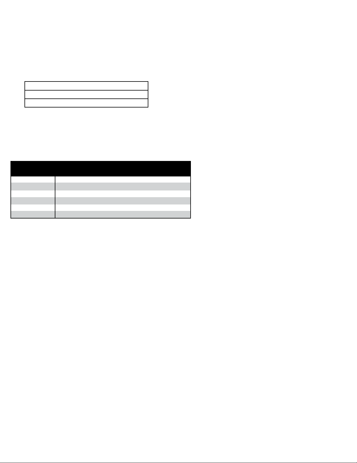
of another power failure. The suggested battery backup consists of eight AA batteries,
however, a standard nine volt battery could be used to provide approximately one hour of
backup. The following chart shows the life expectancy of various types of batteries.
Batteries
Eight AA Alkaline Batteries (Included) 48 Hours
Eight Rechargeable Nicad AA Batteries 24 Hours
Standard 9 Volt Alkaline Battery 1 Hour
Charts
Temperature Chart Speeds
Ranges 12 Hours 24 Hours 7 Days 31 Days
-20 to +120°F E20120F12 E20120F24 E20120F7 E20120F3
-20 to +50°F E2050F12 E2050F24 E2050F7 E2050F31
+40 to +110°F E40110F12 E40110F24 E40110F7 E40110F31
-30 to +50°C E3050C12 E3050C24 E3050C7 E3050C31
-30 to +10°C E3010C12 E3010C24 E3010C7 E3010C31
+5 to +45°C E545C12 E545C24 E545C7 E545C31
*NOTE: For 1.5 Hour, 3 Hour and 6 Hour readings, use the 12 Hour charts.
11
Page 12

CTH89 SPECIFICATIONS
Operating Ambient Temperature Range +32°F to +120°F (0 to +50°C)
Storage Temperature 0°F to +120°F (-18°C to +50°C)
Primary Power 115VAC, 50/60 Hz. Plug-in Adapter
(220-240VAC, 50 Hz. optional)
Backup Power 8 AA alkaline batteries (Approx. 48 Hrs.)
Alternative Power 12 Volt vehicle operation with optional
adapter
Temperature Accuracy +/- 2°F (+/- 1°C)
Relative Humidity Range 0 - 100%
Relative Humidity Accuracy +/- 2%
Dew Point Range +32°F to +130°F (0°C to +50°C)
Sensor Supco Part #KTH. Combined
Temperature/Humidity with 6’ cable
(extended cable length is available)
Chart 6” Circular chart (see following table)
Chart Rotation Speeds 31 Days, 7 Days, 24 Hours,
12 Hours, 6 Hours, 3 Hours or1.5 Hours
Chart Rotation Mode User Selectable — Single turn or continuous
Chart Speed Accuracy +/- 1 %
Display Alphanumeric backlit LCD,
16 Characters, 2 Lines
Temperature Alarm Range -20°F to +120°F (-30°C to +50°C)
Alarm Delay Range User Selectable: No Delay, 10 Min.,
30 Min., 1 Hr. or 2 Hr.
Remote Alarm Connection Normally open contacts 48 VAC/ DC,
0.1 Amp., dry contacts
Mounting Vertical or horizontal,
Free standing or wall mounted
Dimensions 9.25” x 7.25” x 2.75”
Weight 2.5 lb.
Power Consumption 3.5 Watts maximum
Accessories
Part # Description
CRT-110V-ADAPTOR 110V AC ADAPT.CT82, CT87, CTH89
CRT-220V 220V POWER ADAPTER
CTH89-PEN-RED Replacement Red Pen (shelf life is one year)
CTH89-PEN-BLUE Replacement Blue Pen (Humidity) (shelf life is one year)
CTH89-RP Replacement Probe with 6 ft. Cable
CTH89C-MIX Mix Box of Assr ted Charts (5 of each range)
MN1500 AA Batteries (pack of 2)
12
Page 13

NOTES
13
Page 14

NOTES
14
Page 15

15
WARRANTY/ DISCLAIMER
OMEGA ENGINEERING, INC. warrants this unit to be free of defects in materials and workmanship for a
period of 13 months from date of purchase. OMEGA’s WARRANTY adds an additional one (1) month
grace period to the normal one (1) year product warranty to cover handling and shipping time. This
ensures that OMEGA’s customers receive maximum coverage on each product.
If the unit malfunctions, it must be returned to the factory for evaluation. OMEGA’s Customer Service
Department will issue an Authorized Return (AR) number immediately upon phone or written request.
Upon examination by OMEGA, if the unit is found to be defective, it will be repaired or replaced at no
charge. OMEGA’s WARRANTY does not apply to defects resulting from any action of the purchaser,
including but not limited to mishandling, improper interfacing, operation outside of design limits,
improper repair, or unauthorized modification. This WARRANTY is VOID if the unit shows evidence of
having been tampered with or shows evidence of having been damaged as a result of excessive corrosion;
or current, heat, moisture or vibration; improper specification; misapplication; misuse or other operating
conditions outside of OMEGA’s control. Components in which wear is not warranted, include but are not
limited to contact points, fuses, and triacs.
OME GA is pleased to offer s uggesti ons o n the use o f its various products. Ho wever,
OMEGA neither assumes responsibility for any omissions or errors nor assumes liability for any
damages that result from the use of its products in accordance with information provided by
OMEGA, either verbal or written. OMEGA warrants only that the parts manufactured by the
company will be as specified and free of defects. OMEGA MAKES NO OTHER WARRANTIES OR
REPRESENTATIONS OF ANY KIND WHATSOEVER, EXPRESSED OR IMPLIED, EXCEPT THAT OF
TITLE, AND ALL IMPLIED WARRANTIES INCLUDING ANY WARRANTY OF MERCHANTABILITY
AND FITNESS FOR A PARTICULAR PURPOSE ARE HEREBY DISCLAIMED. LIMITATION OF
LIABILITY: The remedies of purchaser set forth herein are exclusive, and the total liability of
OMEGA with res pect to this order, whe ther base d on contract, warranty, negligence,
indemnification, strict liability or otherwise, shall not exceed the purchase price of the
co mpone nt u po n which liabil ity is bas ed. In no eve nt s ha ll O MEGA be l iable fo r
consequential, incidental or special damages.
CONDITIONS: Equipment sold by OMEGA is not intended to be used, nor shall it be used: (1) as a “Basic
Component” under 10 CFR 21 (NRC), used in or with any nuclear installation or activity; or (2) in medical
applications or used on humans. Should any Product(s) be used in or with any nuclear installation or
activity, medical application, used on humans, or misused in any way, OMEGA assumes no responsibility
as set forth in our basic WARRANTY/DISCLAIMER language, and, additionally, purchaser will indemnify
OMEGA and hold OMEGA harmless from any liability or damage whatsoever arising out of the use of the
Product(s) in such a manner.
RETURN REQUESTS/INQUIRIES
Direct all warranty and repair requests/inquiries to the OMEGA Customer Service Department. BEFORE
RETURNING ANY PRODUCT(S) TO OMEGA, PURCHASER MUST OBTAIN AN AUTHORIZED RETURN
(A R) N UM BER FR OM OME GA’ S CUST OM ER S ERVI CE DEPA RT ME NT ( IN OR DER TO AVOI D
PROCESSING DELAYS). The assigned AR number should then be marked on the outside of the return
package and on any correspondence.
The purchaser is responsible for shipping charges, freight, insurance and proper packaging to prevent
breakage in transit.
FOR WARRANTY
RETURNS, please have the
following information available BEFORE
contacting OMEGA:
1. Purchase Order number under which the product
was PURCHASED,
2. Model and serial number of the product under
warranty, and
3. Repair instructions and/or specific problems
relative to the product.
FOR NON-WARRANTY REPAIRS,
consult OMEGA
for current repair charges. Have the following
information available BEFORE contacting OMEGA:
1. Purchase Order number to cover the COST
of the repair,
2. Model and serial number of the product, and
3. Repair instructions and/or specific problems
relative to the product.
OMEGA’s policy is to make running changes, not model changes, whenever an improvement is possible. This affords
our customers the latest in technology and engineering.
OMEGA is a registered trademark of OMEGA ENGINEERING, INC.
© Copyright 2011 OMEGA ENGINEERING, INC. All rights reserved. This document may not be copied, photocopied,
reproduced, translated, or reduced to any electronic medium or machine-readable form, in whole or in part, without the
prior written consent of OMEGA ENGINEERING, INC.
Page 16

M0000/0011
Where Do I Find Everything I Need for
Process Measurement and Control?
OMEGA…Of Course!
Shop online at omega.com
SM
TEMPERATURE
Thermocouple, RTD & Thermistor Probes, Connectors, Panels & Assemblies
Wire: Thermocouple, RTD & Thermistor
Calibrators & Ice Point References
Recorders, Controllers & Process Monitors
Infrared Pyrometers
PRESSURE, STRAIN AND FORCE
Transducers & Strain Gages
Load Cells & Pressure Gages
Displacement Transducers
Instrumentation & Accessories
FLOW/LEVEL
Rotameters, Gas Mass Flowmeters & Flow Computers
Air Velocity Indicators
Turbine/Paddlewheel Systems
Totalizers & Batch Controllers
pH/CONDUCTIVITY
pH Electrodes, Testers & Accessories
Benchtop/Laboratory Meters
Controllers, Calibrators, Simulators & Pumps
Industrial pH & Conductivity Equipment
DATA ACQUISITION
Data Acquisition & Engineering Software
Communications-Based Acquisition Systems
Plug-in Cards for Apple, IBM & Compatibles
Data Logging Systems
Recorders, Printers & Plotters
HEATERS
Heating Cable
Cartridge & Strip Heaters
Immersion & Band Heaters
Flexible Heaters
Laboratory Heaters
ENVIRONMENTAL
MONITORING AND CONTROL
Metering & Control Instrumentation
Refractometers
Pumps & Tubing
Air, Soil & Water Monitors
Industrial Water & Wastewater Treatment
pH, Conductivity & Dissolved Oxygen Instruments
M2458/0311
 Loading...