

Page 1

INTRODUCTION
The CT87E is a precision instrument used to monitor and record the presence or
absence of voltage, light, or sound level such as what would be produced by an
operating electric motor or compressor. The CT87E may be carried as a portable
instrument or mounted in a fixed location.
The CT87E offers a variety of features to meet any event recording
requirements. A combination of three adapters and four chart speeds provide a
high degree of flexibility. In addition the chart rotation may be set for single or
continuous turn operation as required by a particular application. To protect the
data being recorded the CT87E uses an automatic battery backup to maintain
operation during a power outage.
CT87E FEATURES AND CONTROLS
1. The 3 DIGIT COUNT / TIME DISPLAY provides the operator with the total
number of “ON” events, or the interval between each “ON” event, or the total
number of events that have occurred during the monitoring period. When the
CT87E is operating on battery power the display will flash once every several
seconds to indicate battery operation and conserve battery power. When the
batteries are nearly discharged, the display will alternate the display reading and
“LO” to advise the operator that the batteries are discharged and the CT87E will
shortly cease operation.
NOTE: The battery backup feature of the CT87E is primarily intended for use in
situations where primary power is lost for short periods of up to 48 Hrs. The
CT87E is not intended to be used as a battery powered instrument. If the CT87E
is to be stored for an extended period of time, it is strongly advised to disconnect
the battery pack and remove the batteries to avoid damage to the instrument
from battery leakage.
2. The DISPLAY FUNCTION SELECTOR allows the user to select the function of
the LED display. The total number of events, the interval between the start of each
event or the time of the last “ON” period may be selected by this switch.
3. The CHART SPEED SELECTOR allows the user to select the time of one full
chart revolution. The corresponding chart has to be chosen according to the
desired chart speed. Chart part numbers are listed on page 7 of this manual.
4. The PEN POSITION ADJUSTMENT KNOB allows the user to adjust the
position of the chart pen. To achieve maximum usage of each chart two separate
scales are supplied allowing each chart to be used twice.
5. The CHART ADVANCE BUTTON allows the operator to set the chart to the
correct time. Press and hold the chart advance button until the desired time lines
up with the Time Pointer (Item 11). The chart rotates counterclockwise only.
CAUTION: Movement of the Chart Spindle (Item 9) by hand may cause
permanent damage to the chart mechanism.
1
Page 2

6. The RESET button allows the operator to clear the reading on the display. The
total number of events, the length of the last “ON” period, and the interval between
the last event are set to zero. These values are also reset to zero when power is
applied to the CT87E.
7. The POWER ON/OFF / CONTINUOUS / SINGLE CHART SELECTOR allows
the user to apply power to the CT87E and to select Continuous or Single Turn for
the chart rotation. When power is first applied to the CT87E, the display will show
“888” to test each segment of the display, and the pen will move to the edge of the
chart. The pen will then move to the correct position on the chart. In the Continuous
switch position, the chart will rotate until power is removed. In the Single Turn
switch position, the chart will make one complete revolution and stop. A blinking
dot on the display (Item 1) will indicate that the chart has made one complete
revolution and stopped. To reset the chart for another revolution place the
switch in the Continuous switch position until the blinking dot goes out, and then
slide the switch back to the Single Turn position. The chart will make one complete
revolution and stop.
DO NOT move the pen by hand or interrupt the pen movement. Failure to observe
this will cause the pen to read incorrectly and may result in damage to the pen
mechanism.
8. The RECORDING PEN contains special ink. The pen has a wrap-around arm
latch which makes the pen replacement “A SNAP!” To replace the pen, gently lift
up the PEN ARM, (do not over bend pen arm) release the pen latch by pushing it
down, and remove the pen; place a new pen on top of the pen arm, align the
notches on the pen arm with the notches on the pen latch and close the latch by
wrapping it around the pen holder until it is secured. Replace cap on the pen tip
when the CT87E is not used to insure long pen life. For pen installation see Fig. 1.
9. The CHART SPINDLE holds and rotates the chart during the recording
operation. DO NOT ROTATE THE SPINDLE BY HAND AS IT MAY DAMAGE
THE INTERNAL MECHANISM.
10. The PAPER CHART is 6 inches in diameter. Four different charts may be used
with the CT87E depending on the selected chart speed. The replacement charts
are available from Omega in a box of 60 charts each. The chart part numbers are
listed on page 6 of this manual.
TO INSTALL A NEW CHART ... Disconnect power from the CT87E by selecting
OFF with the Power / Single / Continuous Chart Selector. Place pen cap on pen
point. Gently lift the pen arm and while holding it, remove the old chart. Slide a new
chart under the pen holder and the chart holding tabs. Align the chart with the chart
spindle. Apply power to the CT87E and rotate the chart by depressing the chart
advance button until the time pointer is aligned with the line on the chart
representing the right time or day. Remove the pen cap. If desired, adjust the pen
position according to the scale you wish to record on.
11. The TIME POINTER is simply a point against which the current time is being
read during a chart rotation. Initially a new chart has to be rotated until the time
pointer shows the right time and day when using a chart.
2
Page 3

12. The HANDLE for carrying folds towards the back of the case to be out of the
way when CT87E is mounted on the panel or on the wall.
13. The KEYHOLE SLOTS located on the back of the case are provided for wall or
panel mounting.
14. The REAR COMPARTMENT was designed to store the battery holder for
battery backup as well as the connection for the adapter box.
15. The CT87E is supplied with three different adapters. Each adapter detects a
different type of event.
KEV VOLTAGE EVENT ADAPTER
The KEV is used to detect the presence or absence of AC or DC voltage.
Two clip leads are provided to connect to the unit under test. Operation of
the voltage detector outside the specified range may cause
permanent damage to the adapter and the CT87E.
CAUTION!
Electrical connection to any type of operating equipment is dangerous!! The voltage detector leads should only be connected when it
has been determined that the power is off and the equipment is safe
to touch!
KEL LIGHT EVENT ADAPTER
The KEL is used to detect if the level of light illuminating the module is
above or below an adjustable threshold. A user adjustment is provided to
allow the KEL to be adjusted to the desired illumination threshold.
KES SOUND EVENT ADAPTER
The KES is similar to the KEL except that the KES responds to levels of
sound. An adjustable sensitivity control is provided to allow the user to set
the sound level threshold that the KES will respond to.
Each adapter will be discussed in more detail under the applications section
of this manual.
16. The BATTERY HOLDER is stored in the rear compartment for backup
batteries. Use of 8 alkaline “AA” batteries is required for proper operation.
17. The 12VDC PLUG IN WALL ADAPTER provides primary power for the
CT87E. Alternate sources of 12 Volt power may also be used. This allows use of
the CT87E in automotive, marine or other mobile applications.
18. The POWER CONNECTOR is a connection point for the 12VDC wall adapter
or alternate source of 12VDC power.
19. Snap on EXTRA SUPPORT LEGS for better stability.
3
Page 4
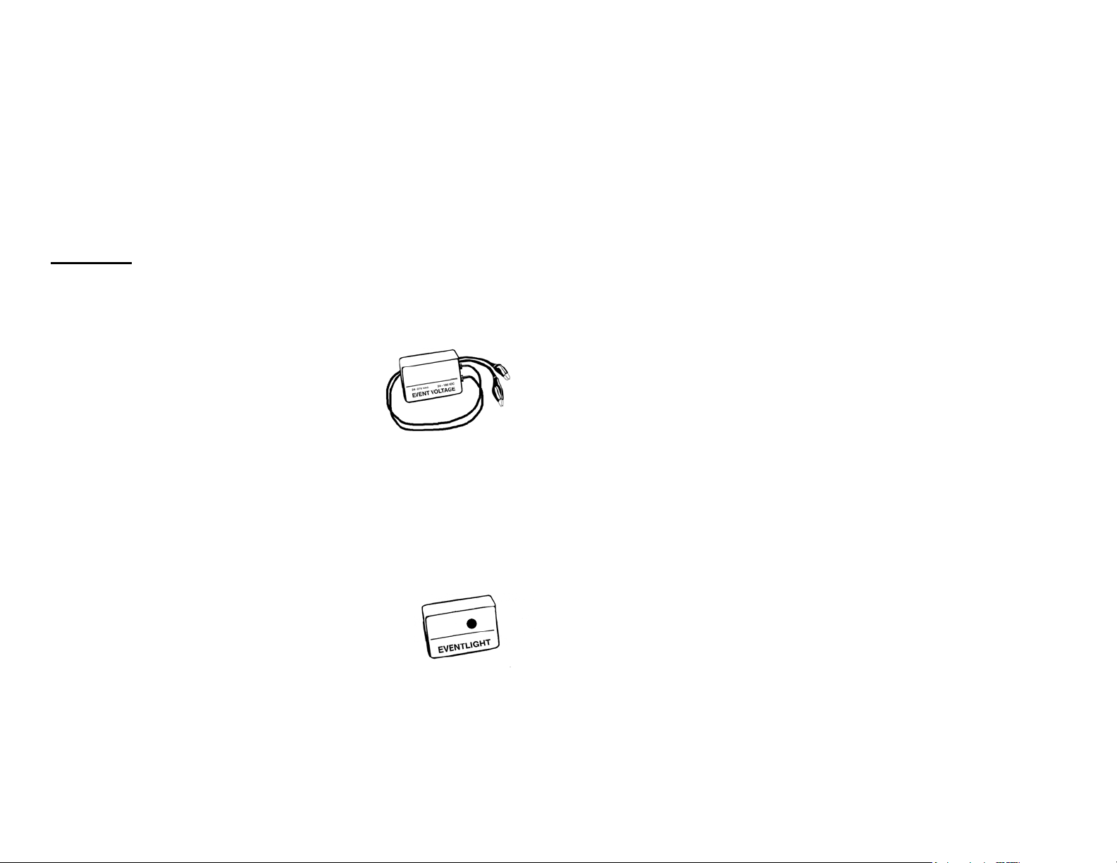
KEV VOLTAGE EVENT ADAPTER APPLICATION
The KEV adapter detects the presence or absence of voltage in the range of
24VAC to 270VAC and 24VDC to 180VDC. The voltage detector used in the KEV
is an electronic optically isolated circuit which will detect when a unit under test has
voltage applied to it. Since the adapter is optically coupled, the CT87E is
completely isolated from the unit being tested. This means that no special
provisions have to be made for grounding or for differences in operating voltage
between the unit under test and the CT87E. The KEV adapter connects to the
CT87E by means of the supplied interface cable. Connect the KEV adapter to the
CT87E prior to starting a new recording. Connect each clip lead to the points being
tested. Any dirt, corrosion or oil should be cleaned prior to connecting the clip
leads. There are no user adjustments on this adapter.
CAUTION!
Electrical connection to any type of operating equipment is dangerous!!
The voltage detector leads should only be connected when it has been determined that the power is off and the equipment is safe to touch!
Set the controls of the CT87E for the desired operation.
Refer to opening section of this manual for a description
and location of each adjustment and control. Make sure
that the selected chart matches the Chart Speed setting
and that the time is correctly set at the beginning of each
recording. A scrap chart may be used during the initial
setup to avoid unnecessary marks on the final recording.
KEL LIGHT EVENT ADAPTER APPLICATION
The KEL adapter uses a sensitive photocell which compares the intensity of the
ambient light to an adjustable threshold. The threshold adjustment knob is located on the side of the KEL adapter box. The Threshold Adjustment sets the
level of light which the CT87E will recognize as an “ON” condition. The full
counterclockwise position of the adjustment corresponds to a very low level of
illumination being recognized as “ON” while the full clockwise position of the adjustment will require very bright light to be recognized as an “ON” condition.
The adjustment of the KEL adapter is best illustrated by example.
In this example it is desired to determine the cycle of light
use for a given room. The CT87E is set for a 24 Hour chart
speed and the KEL adapter has been connected. The room
light is turned on and while observing the chart pen position the
operator adjusts the Threshold Adjustment knob until the chart
pen moves to the “ON” position. The operator then turns off the
room lighting (or covers the photocell) and determines that the
chart pen moves to the “OFF” range of the recording chart. If it does not, the
Threshold Adjustment is turned slowly clockwise until the chart pen moves to the
“OFF” portion of the recording chart. Once the Threshold Adjustment is
accomplished the operator may wish to reset the LED Display prior to starting the
actual recording to get accurate count and interval information. During this initial
adjustment it is suggested to use a scrap chart so as not to leave random marks on
the actual recording chart. This is entirely at the option of the operator and is not
4
Page 5

required for the setup of the CT87E. The resulting recording will show when, and
for how long, the room lights were used over a 24 hour period. The above example
is only one of many possible applications of the KEL adapter.
KES SOUND EVENT ADAPTER APPLICATION
The KES adapter works much like the KEL adapter except that the KES adapter
responds to the intensity of sound instead of illumination. The KES adapter uses
a sensitive audio transducer to pick up sound from the surrounding environment
and compare it to the adjustable threshold. When the sound level exceeds the
threshold setting it is recognized as an “ON” condition and the chart pen will
move to the corresponding portion of the chart. When the sound level falls below
the threshold setting the KES adapter will recognize this as an “OFF” condition
and move the chart pen accordingly. A small delay is built in to the response of
the KES to avoid unintentional responses to transient noises such as door
slams, dropped tools and the like.
The KES adapter uses the same type of threshold setting as the
KEL. It is easiest to think of the threshold adjustment on the KES
as a sensitivity adjustment. At the full counterclockwise setting
only a very loud sound level will be recognized as an “ON”
condition. At the full clockwise setting of the threshold
adjustment
the KES will respond to very low levels of sound. In many cases
the ambient noise in a small room will be sufficient to be
recognized as an “ON” condition with the threshold adjustment at this setting.
An example is the best way to illustrate the use of the KES adapter. In this
example it is desired to know the operating cycle of an air compressor. Since it is
not only impractical to open the electrical box, but represents a safety hazard as
well, the KES adapter provides the ideal solution for this application. The sound
level the compressor produces in operation is well above the ambient noise level of
the rest of the area so the KES can positively identify when the compressor is in
operation.
The important thing to remember about the KES is that it provides a non-contact
means of determining the operation of the device being tested.
The CT87E is set for a chart speed of 24 hours and the KES adapter is attached
to the interface cable. The KES adapter is so positioned that it can not fall into
the machinery or have any personnel trip over the interface cable, or the cord
from the power adapter, yet is close enough to the compressor that it can detect
the change in sound level when the compressor is in operation. The threshold
adjustment is first set fully counterclockwise. When the compressor is operating,
the threshold adjustment is advanced clockwise until the CT87E pen moves into
the “ON” range of the chart.
For best result the threshold adjustment should be set so that the sound level is
just above the detection threshold. If the setting is made too sensitive there is a
chance extraneous noises will cause a “false” reading on the event recording. If the
threshold setting is not made sensitive enough the CT87E may not detect every
operation of the compressor. Best results will be obtained when the threshold setting is about halfway between the ambient sound level and the sound level of the
unit under test. It is easy to understand that this will work best on equipment which
5
Page 6

would normally produce a significant difference in sound levels during operation.
As mentioned in the KEL section a scrap chart may be used during the setup of the
KES to avoid random marks on the final recording.
CT87E CHARTS
CT87C-6H
CT87C-24H
CT87C-7D
CT87C-31D
6 Hours
24 Hours
7 Days
31 Days
CT87E SPECIFICATIONS
KEV RANGE 24VAC to 270VAC (50/60 Hz.), 24VDC to 180VDC
KEL RANGE Illumination Threshold Range, 18 LUX to 1900 LUX
+/- 20%
KES RANGE Sound Threshold Range 40 dB to 114 dB @ 1Khz
+/- 20%
Chart Speed Selectable 6 Hours, 24 Hours, 7 Days, 31 Days
Chart Speed Accuracy +\-1%
Chart Diameter 6 inches
Display 3 Digit 0.5” LED to display event interval in
minutes, length of the event in minutes, and total
number of events
Display range 0 to 999 minutes or event counts
Recording Pen Ink type
Power Supply 120 VAC, 50/60Hz. (Primary) (220/240 VAC 50Hz.
Optional)
Battery Backup 8 Alkaline “AA” cells
Battery Life Continuous, 48 Hours
Operating temperature +32°F to 158°F (0°C to +70°C)
Relative Humidity 96% maximum
Dimensions 9 ¼” x 7 ¼” x 2 ¾”
Weight 4 lbs., 7oz.
M-3967
6
 Loading...