

Page 1
TM
User’s Guide
Shop online at
omega.com
e-mail: [email protected]
For latest product manuals:
www.omegamanual.info
CS8DPT SERIES
Benchtop Controllers
Page 2

omega.com [email protected]
Servicing North America:
U.S.A.
Headquarters:
Omega Engineering, Inc.
Toll-Free: 1-800-826-6342 (USA & Canada only)
Customer Service: 1-800-622-2378 (USA & Canada only)
Engineering Service: 1-800-872-9436 (USA & Canada only)
Fax: (203) 359-7700 Tel: (203) 359-1660
e-mail: [email protected]
For Other Locations Visit omega.com/worldwide
The information contained in this document is believed to be correct, but OMEGA accepts no liability for any errors it contains, and reserves
the right to alter specifications without notice.
Page 3

Table of Contents
Section Page
Section 1 Introduction ...................................................................................... 1
1.1 Precautions
1.2 Safety Warnings and IEC Symbols
CS8DPT Series Benchtop Controllers
................................................................................................... 1
..............................................................1
Section 2 Installation
2.1 Unpacking and Inspection
2.2 Main Power Connection
2.3 Power Cords
Section 3 Operation ......................................................................................... 4
3.1 Front Panel
3.2 Rear Panel
3.3 Sensor Input Wiring
3.5 Controller Setup and Programmming
Section 4 Communication .............................................................................. 7
4.1 Communication Option
4.2 Ethernet
4.3 RS-232/485
Section 5 Maintenance .................................................................................... 8
5.1 Calibration
5.2 Cleaning
5.3 Fuse Replacement
Section 6 Specifications .................................................................................. 9
................................................................................................... 4
..................................................................................................... 4
......................................................................................................... 7
.................................................................................................... 7
.................................................................................................... 8
........................................................................................................ 8
........................................................................................ 2
......................................................................... 2
............................................................................. 3
................................................................................................. 3
.................................................................................... 5
...................................................... 6
.............................................................................. 7
........................................................................................ 8
i
Page 4

CS8DPT Series Benchtop Controllers
NOTES:
ii
Page 5
Section 1 Introduction
Your CS8DPT series Benchtop Controller is ideal for laboratory use and
applications requiring portable temperature measurement and control. The
CS8DPT features a universal input that can be reconfigured by you for use
with a thermocouple, RTD or Voltage/Current signal. These controllers are
factory configured and calibrated. It is important that you read this manual
and additional manuals outlined in Section 6 completely and follow all safety
precautions in both manuals before operating your unit.
1.1 Precautions
• Follow all safety precautions and operating instructions outlined in this manual.
• Keep unit out of reach of all children.
• Do not operate in flammable or explosive environments.
• Never operate with a power cord that is not properly rated for use with your unit.
• Remove and or disconnect main power cord before attempting any
maintenance or fuse replacement.
• Do not connect and or operate this unit to a non-grounded, non-polarized
outlet or power source.
NOTE:
Introduction
1
There are no user serviceable parts inside your unit. Attempting
to repair or service your unit may void your warranty.
CAUTION:
This product is not designed for use in human medical or
nucleur applications.
1.2 Safety Warnings and IEC Symbols
This device is marked with international safety and hazard symbols in
accordance with EN61010-1. It is important to read and follow all precautions
and instructions in this manual before operating or commissioning this device as
it contains important information relating to safety and EMC. Failure to follow
all safety precautions may result in injury and or damage to your calibrator.
Use of this device in a manor not specified by the manufacturer may impair
protection devices and safety features provided by the unit.
Caution, risk of electric shock Caution, refer to accompanying documents
Figure 1.IEC symbols
CAUTION:
All electrical connections and wiring should be performed by
suitably trained personnel only.
1
Page 6

2
Installation
Section 2 Installation
2.1 Unpacking
Remove the packing list and verify that you have received all your equipment.
If you have any questions about the shipment, please call our Customer Service
Department at
1-800-622-2378 or 203-359-1660.
We can also be reached on the Internet at omega.com
e-mail: [email protected]
When you receive the shipment, inspect the container and equipment for any
signs of damage. Note any evidence of rough handling in transit. Immediately
report any damage to the shipping agent.
The carrier will not honor any damage claims unless all shipping material is saved for inspection. After examining and
removing contents, save packing material and carton in the
event reshipment is necessary.
The following items are supplied with your unit:
• CS8DPT Series Benchtop Controller (1 each)
• Main Power Cord (See Section 2.2.2 Power Cords)
• Output Power Cord (2 each)
• This Users Guide and Controller Manual #M3355 (1 each), Quick Start Manual
#MQS3355 (1 each)
• Communications Manual #M-3629 (1 each) with Ethernet models only.
• Communications Manual #M-3397 (1 each) with RS-232/485 models only.
• Warranty Extension Card (1 each)
NOTE:
2
Page 7

2.2 Main Power Connection
2.2.1 Operation
Your Benchtop Controller will operate from 90 to 240VAC, 50/60 Hz, 2400W.
All power line connections to your unit are fused. When
operating on single-phase power source such as 120VAC in
the U.S.A, the main neutral line is also fused.
2.3 Power Cords
A main power cord has been included with your unit.The following optional
power cords are also available for use with your Benchtop Controller.
Omega Part No.
POWER CORD-UK POWER CORD-IT
(United Kingdom, Ireland, 250V) (Italy, 250V)
NOTE:
Installation
2
POWER CORD-DM POWER CORD-E-10A
(Denmark, 250V) (Continental Europe, 250V)
POWER CORD-NA POWER CORD-SE
(USA, Canada, Mexico, 120V) (Striped Leads, 250V)
CAUTION:
All electrical connections and wiring should be performed by
suitably trained personnel only.
3
Page 8
3
Operation
Section 3 Operation
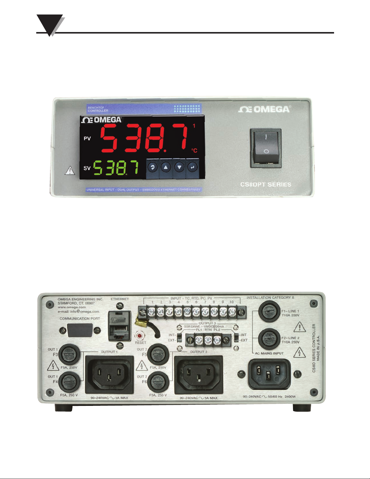
3.1 Front Panel Controls, Indicators
Figure 3.1 Front Panel Controls, Indicators
3.2 Rear Panel Controls and Connections
Figure 3-2 Rear Panel Controls and Connections
4
Page 9
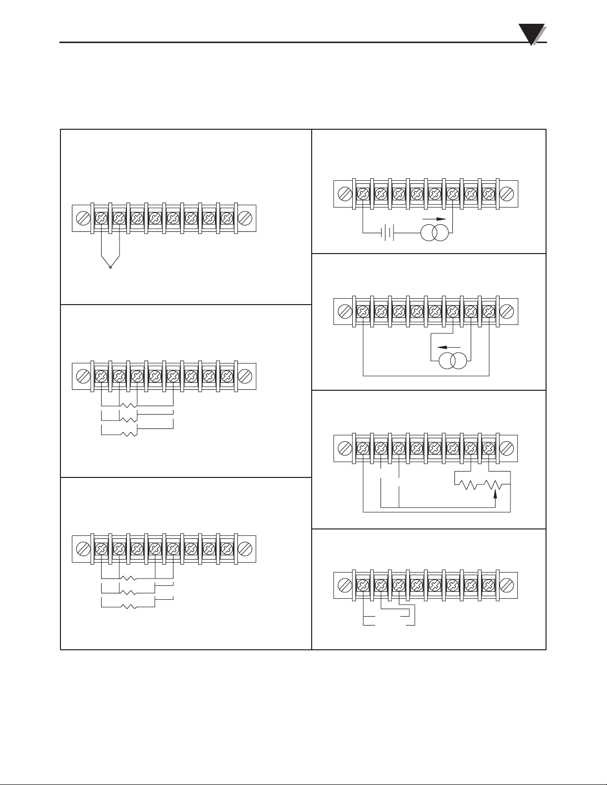
3.3 Universal Input, Sensor Wiring
THERMOCOUPLE CONNECTION
Operation
PROCESS CURRENT INPUT (EXTERNAL EXCITATION)
3
2
1
4
6
5
8
7
3
1
1
3
2
+–
500/1000 OHM RTD CONNECTION
2
4
3
4576
56
8
7
8
RTD (500/1000) 4-WIRE
RTD (500/1000) 3-WIRE - ADD JUMPER
RTD (500/1000) 2-WIRE - ADD JUMPER
+–
PROCESS CURRENT INPUT (INTERNAL EXCITATION)
1
37456
2
–+
8
JUMPER
+–
PROCESS VOLTAGE INPUT (WITH INTERNAL EXCITAT ION)
1
2
100 mV
1V or 10V
43576
8
100 OHM RTD CONNECTION
1
3
2 4576
8
RTD (100) 4-WIRE
RTD (100) 3-WIRE - ADD JUMPER
RTD (100) 2-WIRE - ADD JUMPER
Figure 3.3 Universal Input, Sensor Wiring
PROCESS VOLTAGE INPUT (WITHOUT EXTERNAL EXCITATION)
1
2
100 mV
1V or 10V
3
654
8
7
5
Page 10

3
Installation
3.5 Controller Setup and Programming
3.5.1 Factory Configuration
All units are factory configured and calibrated for Type-K thermocouple unless
a different setup was requested when you ordered your unit. Your unit can be
reconfigured in the field to a different input type without the need to recalibrate
the controller. The procedure for changing the controllers programming can be
found in the accompanying manual M3355.
6
Page 11
Section 4 Communication Option
4.1 Communication (Ethernet, RS-232/485)
Your controller has been factory pre-wired and configured for ease of use with
your communication option. Connections are made on the rear panel.
4.2 Ethernet
The RJ45 connection on the back of the controller has been extended out to the
rear panel on your Benchtop meter. Connection and use of the ethernet option is
outlined in manual #M3629 that was included with your unit.
4.3 RS-232/485
Your controller has been factory pre-wired and configured for ease of use with a
standard DB9 female connector on the rear panel. Page 6 of your communication
manual #M3397 shows how your rear panel connector has been wired.
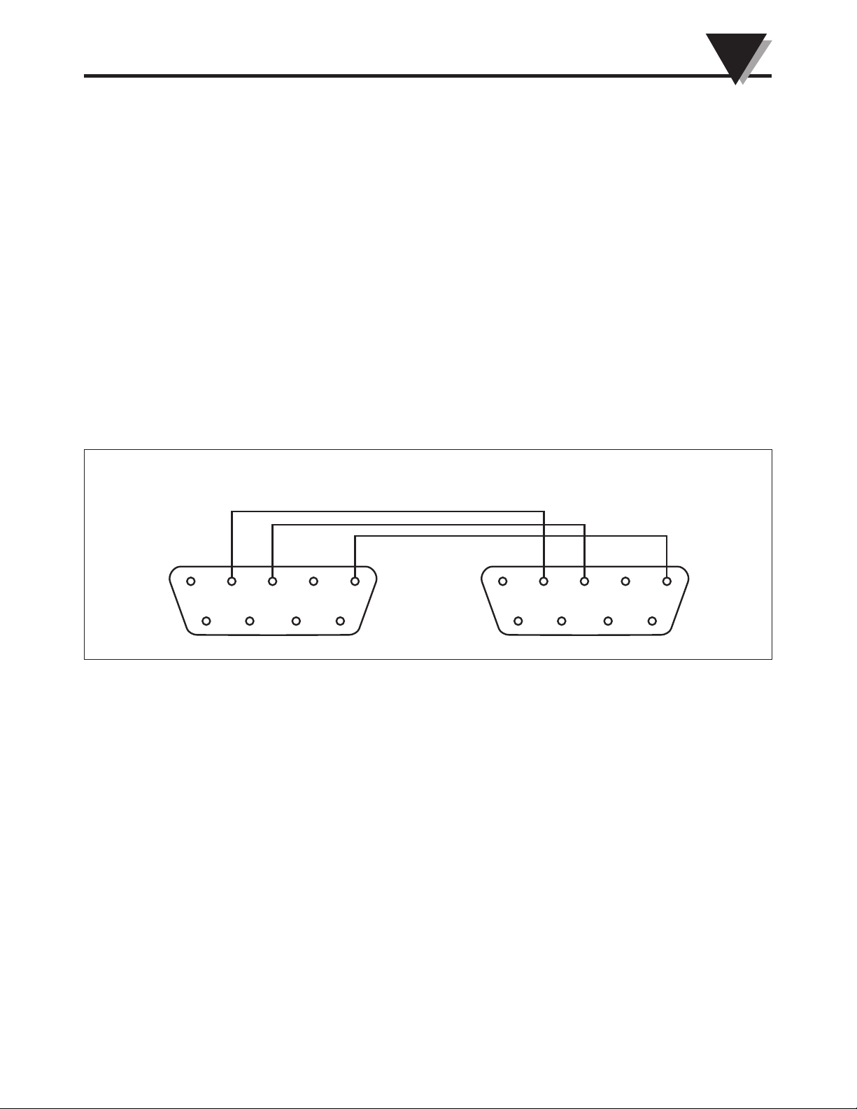
Connections to your PC should be straight through wiring as shown below.
Communications Option
4
BENCHTOP METER
REAR PANEL
1
2345
67
89
YOUR PC
1
2345
67 89
Figure 4.3 Wiring Diagram
7
Page 12

5
Maintenance
Section 5 Maintenance
5.1 Calibration
This unit has been fine-tuned and factory calibrated to give optimum
performance over its full operating range. Refer to manual M3355 for additional
information on meter calibration and setup.
Remove all electrical connections and power before attempting any maintenance or cleaning.
5.2 Cleaning
Lightly dampen a soft clean cloth with a mild cleaning solution and gently clean
the benchtop meter.
5.3 Fuse Specifications and Replacement
CAUTION:
WARNNG:
Disconnect all power from source before attempting fuse
replacement.
CAUTION:
For continued protection against the risk of fire, replace fuses
with only the same size, type, rating and safety approvals
indicated here and on the rear panel of your unit.
NOTE:
All power line connections to your unit are fused. When operating on single-phase power source such as 120VAC in the
USA, the neutral line is also fused.
5.3.1 All Models - 90 to 230VAC 50/60 Hz, 4W
Main Power Fusing: 2ea, T0.1A, 250 VAC, (Time-Lag)
(Rear Panel) F1,F2 UL./CSA/VDE Approved (5mm dia. x 20mm
long).
8
Page 13

Section 6 Specifications
Specifications
6
6.1 Benchtop Configuration
All other specifications are located in your accompanying
manual(s)
Model CS8DPT:
with Ethernet: Manual #M3629
with RS232/485: Manual #M3397
Sensor Input(s)/Channels:
Model CS8DPT Single Channel, Universal Input
Power:
All Models: 90 to 240 Vac, 50/60 Hz, 2400W
Fused: Time-Lag, 0.1A, 250V
Output:
All Models: 90 to 240 Vac, 50/60 Hz, 1200W
Fused: Fast-Blow, 5A, 250V
Manual #M3355, MQS3355
NOTE:
Enclosure:
Material: Case - Painted Aluminum, Handle – Anodized
Aluminum
Size: 20.95 W x 9.525 Hx 20.32 cm D
(8.25 W x 3.75 H x 8” D)
Weight:
1.36 kg (3 lbs.)
9
Page 14

Notes
NOTES:
10
Page 15

WARRANTY/DISCLAIMER
OMEGA ENGINEERING, INC. warrants this unit to be free of defects in materials and workmanship for a
period of 61 months from date of purchase. OMEGA’s WARRANTY adds an additional one (1) month
grace period to the normal five (5) year product warranty to cover handling and shipping time. This
ensures that OMEGA’s customers receive maximum coverage on each product.
If the unit malfunctions, it must be returned to the factory for evaluation. OMEGA’s Customer Service
Department will issue an Authorized Return (AR) number immediately upon phone or written request.
Upon examination by OMEGA, if the unit is found to be defective, it will be repaired or replaced at no
charge. OMEGA’s WARRANTY does not apply to defects resulting from any action of the purchaser,
including but not limited to mishandling, improper interfacing, operation outside of design limits,
improper repair, or unauthorized modification. This WARRANTY is VOID if the unit shows evidence of
having been tampered with or shows evidence of having been damaged as a result of excessive corrosion;
or current, heat, moisture or vibration; improper specification; misapplication; misuse or other operating
conditions outside of OMEGA’s control. Components in which wear is not warranted, include but are not
limited to contact points, fuses, and triacs.
OMEGA is pleased to offer suggestions on the use of its various products. However,
OMEGA neither assumes responsibility for any omissions or errors nor assumes liability for
any damages that result from the use of its products in accordance with information provided
by OMEGA, either verbal or written. OMEGA warrants only that the parts manufactured by the
company will be as specified and free of defects. OMEGA MAKES NO OTHER WARRANTIES OR
REPRESENTATIONS OF ANY KIND WHATSOEVER, EXPRESSED OR IMPLIED, EXCEPT THAT OF
TITLE, AND ALL IMPLIED WARRANTIES INCLUDING ANY WARRANTY OF MERCHANTABILITY
AND FITNESS FOR A PARTICULAR PURPOSE ARE HEREBY DISCLAIMED. LIMITATION OF
LIABILITY: The remedies of purchaser set forth herein are exclusive, and the total liability of
OMEGA with respect to this order, whether based on contract, warranty, negligence,
indemnification, strict liability or otherwise, shall not exceed the purchase price of the
component upon which liability is based. In no event shall OMEGA be liable for
consequential, incidental or special damages.
CONDITIONS: Equipment sold by OMEGA is not intended to be used, nor shall it be used: (1) as a “Basic
Component” under 10 CFR 21 (NRC), used in or with any nuclear installation or activity; or (2) in medical
applications or used on humans. Should any Product(s) be used in or with any nuclear installation or
activity, medical application, used on humans, or misused in any way, OMEGA assumes no responsibility
as set forth in our basic WARRANTY/DISCLAIMER language, and, additionally, purchaser will indemnify
OMEGA and hold OMEGA harmless from any liability or damage whatsoever arising out of the use of the
Product(s) in such a manner.
RETURN REQUESTS/INQUIRIES
Direct all warranty and repair requests/inquiries to the OMEGA Customer Service Department. BEFORE
RETURNING ANY PRODUCT(S) TO OMEGA, PURCHASER MUST OBTAIN AN AUTHORIZED RETURN
(AR) NUMBER FROM OMEGA’S CUSTOMER SERVICE DEPARTMENT (IN ORDER TO AVOID PROCESSING DELAYS). The assigned AR number should then be marked on the outside of the return package and
on any correspondence.
The purchaser is responsible for shipping charges, freight, insurance and proper packaging to prevent
breakage in transit.
FOR WARRANTY RETURNS, please have the
following information available BEFORE contacting
OMEGA:
1. Purchase Order number under which the product
was PURCHASED,
2. Model and serial number of the product under
warranty, and
3. Repair instructions and/or specific problems
relative to the product.
OMEGA’s policy is to make running changes, not model changes, whenever an improvement is possible. This affords
our customers the latest in technology and engineering.
OMEGA is a registered trademark of OMEGA ENGINEERING, INC.
© Copyright 2015 OMEGA ENGINEERING, INC. All rights reserved. This document may not be copied, photocopied,
reproduced, translated, or reduced to any electronic medium or machine-readable form, in whole or in part, without the
prior written consent of OMEGA ENGINEERING, INC.
FOR NON-WARRANTY REPAIRS,
OMEGA for current repair charges. Have
the following information available BEFORE
contacting OMEGA:
1. Purchase Order number to cover the COST
of the repair,
2. Model and serial number of the product, and
3. Repair instructions and/or specific problems
relative to the product.
consult
Page 16

Where Do I Find Everything I Need for
Process Measurement and Control?
OMEGA…Of Course!
Shop online at omega.com
TEMPERATURE
MU
Thermocouple, RTD & Thermistor Probes, Connectors, Panels & Assemblies
MU
Wire: Thermocouple, RTD & Thermistor
MU
Calibrators & Ice Point References
MU
Recorders, Controllers & Process Monitors
MU
Infrared Pyrometers
PRESSURE, STRAIN AND FORCE
MU
Transducers & Strain Gages
MU
Load Cells & Pressure Gages
MU
Displacement Transducers
MU
Instrumentation & Accessories
FLOW/LEVEL
MU
Rotameters, Gas Mass Flowmeters & Flow Computers
MU
Air Velocity Indicators
MU
Turbine/Paddlewheel Systems
MU
Totalizers & Batch Controllers
pH/CONDUCTIVITY
MU
pH Electrodes, Testers & Accessories
MU
Benchtop/Laboratory Meters
MU
Controllers, Calibrators, Simulators & Pumps
MU
Industrial pH & Conductivity Equipment
DATA ACQUISITION
MU
Data Acquisition & Engineering Software
MU
Communications-Based Acquisition Systems
MU
Plug-in Cards for Apple, IBM & Compatibles
MU
Data Logging Systems
MU
Recorders, Printers & Plotters
HEATERS
MU
Heating Cable
MU
Cartridge & Strip Heaters
MU
Immersion & Band Heaters
MU
Flexible Heaters
MU
Laboratory Heaters
ENVIRONMENTAL
MONITORING AND CONTROL
MU
Metering & Control Instrumentation
MU
Refractometers
MU
Pumps & Tubing
MU
Air, Soil & Water Monitors
MU
Industrial Water & Wastewater Treatment
MU
pH, Conductivity & Dissolved Oxygen Instruments
M3906/0919
 Loading...