

Page 1
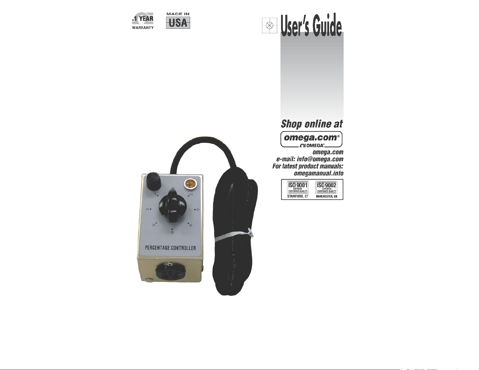
OMEGALUX™ CPP SERIES
Portable Time Percentage Dial
Temperature Controllers
Page 2
TABLE OF CONTENTS
IMPORTANT SAFETY INSTRUCTIONS
Introduction...................................................................
Safety Alert Symbol.......................................................
Important Safety Instructions……………......................
Specifi cations and Drawings.........................................
Installation / Operating Instructions.……......................
Troubleshooting Guide..................................................
Contacting OMEGA.....……………………………..........
Warranty / Disclaimer....................................................
Return Requests / Inquires...........................................
2
2
3
4
5
6
7
Back
Back
INTRODUCTION
The OMEGALUX™ CPP Series Percentage Controller is a manually adjustable
control which provides continuously variable selection of average heater power
ranging from 5% to 100%. The controller varies the proportion of “off” and “on”
time of the heater power. Thermal characteristics of the heated item will
determine the setting of the manually adjustable controller knob. The
controller does not use a temperature sensor and therefore satisfactory
operation requires occasional supervision under changing load conditions.
SAFETY ALERT SYMBOL
The symbol above is used to call your attention
to instructions concerning your personal safety.
It points out important safety precautions. It
means “ATTENTION! Become Alert! Your
Personal Safety is involved!” Read the
message that follows and be alert to the
possibility of personal injury or death.
Immediate hazards which WILL result in severe
Hazards or unsafe practices which COULD result in
Hazards or unsafe practices which COULD result in
minor personal injury or property damage.
personal injury or death
severe personal injury or death
A person who has not read and
understood all operating instructions
is not qualifi ed to operate this product.
• Do not immerse or spray temperature
controller with liquid.
• Keep volatile or combustible material away
from controller when in use.
• Keep sharp metal objects away from controller.
Failure to observe these warnings may result in
electric shock, risk of fi re, and personal injury.
• Only qualifi ed personnel are allowed to
connect the electrical wiring.
• All electrical wiring must follow local electrical
codes and highly recommend following NEC
Article 427.
• Final installation / wiring is to be inspected by
the authority who has jurisdiction in the area
that the heater and temperature control system
is installed.
• The end-user is responsible for providing a
suitable disconnecting device.
• The end-user is responsible for providing
suitable over-protection device. It is highly
recommended that a ground fault circuit
breaker be used.
Failure to observe these warnings may result in
personal injury or damage to the temperature
controller.
• Inspect all components before
use.
• Do not use control and heating
system if any component is
damaged.
• Do not repair damaged or faulty
controller.
• Do not crush or apply severe
physical stress on any component
of controller, including cord
assembly.
• Unplug controller when not in use.
• Unplug controller before fuse is
changed.
Failure to observe these warnings
may result in personal injury or
damage to the temperature controller
SAVE THESE INSTRUCTIONS!
Additional copies of this manual are available upon request.
© Copyright 2005 OMEGA ENGINEERING, Inc. All rights reserved. This document may not be copied, photocopied,
2
reproduced, translated, or reduced to any electronic medium or machine-readable form, in whole or in part, without the
prior written consent of OMEGA ENGINEERING, INC
© Copyright 2005 OMEGA ENGINEERING, Inc. All rights reserved. This document may not be copied, photocopied,
reproduced, translated, or reduced to any electronic medium or machine-readable form, in whole or in part, without the
prior written consent of OMEGA ENGINEERING, INC
3
Page 3
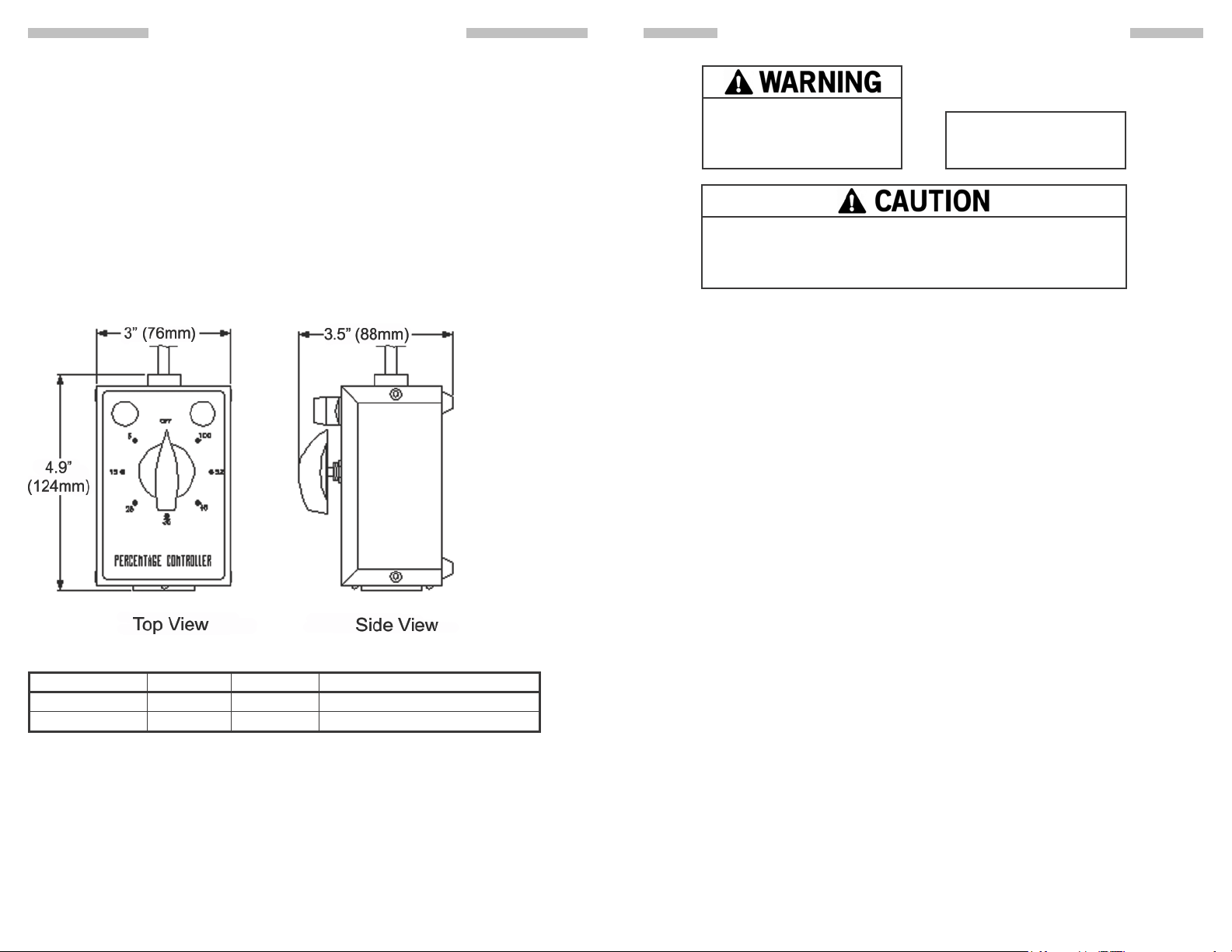
• 120 or 240VAC
• 15 Amp Fuse
• Maximum controller exposure temperatures: -40 to 160°F (-40 to 71°C)
• Range: 5 to 100%
• Enclosure: Cast Aluminum table model with rubber feet. For indoor use.
• Input power cord 6 feet (1.8m) long with standard plug
-120VAC: NEMA 5-15
-240VAC: NEMA 6-15
• Output Receptacle
-120VAC: NEMA 5-15R
-240VAC: NEMA 6-15R
INSTALLATION / OPERATING INSTRUCTIONSSPECIFICATIONS AND DRAWINGS
Read and understand
this entire manual before
operating this controller.
TP0 portable time percentage dial temperature controllers
are designed for temporary use applications and must be
monitored while in operation.
Step 1:
Plug heater into the controller’s output receptacle.
Step 2:
Plug the controller into an approved power source using the Input power cord.
Step 3:
Rotate controller knob to the percentage set-point which will produce the desired
temperature (see Note A).
VOLTAGE:
120VAC; 240VAC
Part Number Volts Amps Range
CPP941 120 15 5 to 100%
CPP942 240 15 5 to 100%
© Copyright 2005 OMEGA ENGINEERING, Inc. All rights reserved. This document may not be copied, photocopied,
4
reproduced, translated, or reduced to any electronic medium or machine-readable form, in whole or in part, without the
prior written consent of OMEGA ENGINEERING, INC
Step 4:
Continue to monitor the controllers performance while in use (see Note B).
Note A:
The time percentage dial controller varies the proportion (length) of time
the heater is in the “on” or “off” heating mode. The heating application will
determine the actual percentage set-point required.
Note B:
The controller does not use a temperature sensor and therefore satisfactory
operation requires occasional supervision under changing load conditions.
© Copyright 2005 OMEGA ENGINEERING, Inc. All rights reserved. This document may not be copied, photocopied,
reproduced, translated, or reduced to any electronic medium or machine-readable form, in whole or in part, without the
prior written consent of OMEGA ENGINEERING, INC
5
Page 4
Please read this guide prior to contacting OMEGA. This guide is designed to
answer the most commonly asked questions. If you are unable to identify the
problem or need additional assistance, please contact us at 1-800-USA-HEAT.
Controller does not function
1. Check fuse:
Unplug the unit from its power source. Remove the fuse located under cap on
front of controller and check its continuity. If the fuse is defective, replace it with
an ABC 15 amp fuse. Fuses may be obtained from most electrical supply houses.
2. Check heater:
Unplug heater from controller and check for continuity. Replace heater if there is
no continuity.
3. Check power source:
Using a voltmeter, test the power source and assure correct voltage is present.
CONTACTING OMEGATROUBLESHOOTING GUIDE
© Copyright 2005 OMEGA ENGINEERING, Inc. All rights reserved. This document may not be copied, photocopied,
6
reproduced, translated, or reduced to any electronic medium or machine-readable form, in whole or in part, without the
prior written consent of OMEGA ENGINEERING, INC
© Copyright 2005 OMEGA ENGINEERING, Inc. All rights reserved. This document may not be copied, photocopied,
reproduced, translated, or reduced to any electronic medium or machine-readable form, in whole or in part, without the
prior written consent of OMEGA ENGINEERING, INC
7
Page 5
M-1031/0307
PN: 10960-12 Rev B
 Loading...